

Page 1
查询HMC410MS8G供应商
12
MICROWAVE CORPORATION
Typical Applications
The HMC410MS8G is ideal for:
• Long Haul Radio Platforms
• Microwave Radio
• VSAT
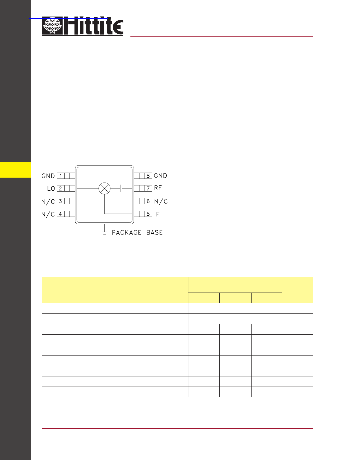
Functional Diagram
v00.1101
HMC410MS8G
GaAs MMIC DOUBLE-BALANCED
HIGH IP3 MIXER, 9.0 - 15.0 GHz
Features
Conversion Loss: 8.0 dB
LO/RF Isolation: 40 dB
LO/IF Isolation: 37 dB
Input IP3: +24 dBm
No External Components
MSOP8G SMT Package
General Description
The HMC410MS8G is a passive double balanced
high IP3 mixer that operates between 9 GHz and
15 GHz. The HMC410MS8G operates with LO
drive levels between +13 dBm and +19 dBm, and
provides 8 dB conversion loss across the entire
specifi ed frequency band. This mixer requires no
external components or bias.
MIXERS - SMT
Electrical Specifi cations, T
Frequency Range, RF & LO 9.0 - 15.0 GHz
Frequency Range, IF DC - 2.5 GHz
Conversion Loss 811dB
Noise Figure (SSB) 811dB
LO to RF Isolation 30 40 - 45 dB
LO to IF Isolation 30 37 dB
RF to IF Isolation 8 17 dB
IP3 (Input) 20 24 dBm
1 dB Compression (Input) 11 14 dBm
* Unless otherwise noted, all measurements performed as downconverter, IF= 1.45 GHz.
12 - 224
= +25° C
A
IF = 1.45 GHz
Parameter
Min. Typ. Max.
For price, delivery, and to place orders, please contact Hittite Microwave Corporation:
12 Elizabeth Drive, Chelmsford, MA 01824 Phone: 978-250-3343 Fax: 978-250-3373
Order Online at www.hittite.com
LO = +17 dBm
Units
Page 2
MICROWAVE CORPORATION
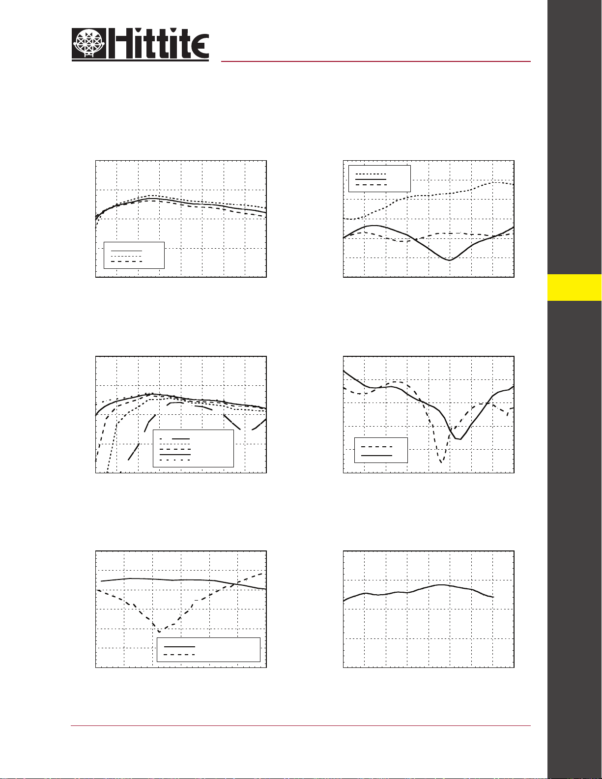
Conversion Gain vs.
Temperature @ LO = +17 dBm
0
-5
v00.1101
HMC410MS8G
GaAs MMIC DOUBLE-BALANCED
HIGH IP3 MIXER, 9.0 - 15.0 GHz
Isolation @ LO = +17 dBm
0
RF/IF
-10
-20
LO/RF
LO/IF
-10
-15
CONVERSION GAIN (dB)
-20
8 9 10 11 12 13 14 15 16
0
-5
-10
-15
CONVERSION GAIN (dB)
-20
8 9 10 11 12 13 14 15 16
+25 C
-40 C
+85 C
FREQUENCY (GHz)
FREQUENCY (GHz)
LO = +11 dBm
LO = +13 dBm
LO = +15 dBm
LO = +17 dBm
LO = +19 dBm
-30
-40
ISOLATION (dB)
-50
-60
8 9 10 11 12 13 14 15 16
FREQUENCY (GHz)
Return Loss @ LO = +17 dBmConversion Gain vs. LO Drive
0
-5
-10
-15
RETURN LOSS (dB)
-20
-25
8 9 10 11 12 13 14 15 16
RF
LO
FREQUENCY (GHz)
12
MIXERS - SMT
IF Bandwidth @ LO = +17 dBm
0
-5
-10
-15
-20
RESPONSE (dB)
-25
-30
0 0.5 1 1.5 2 2.5 3
FREQUENCY (GHz)
For price, delivery, and to place orders, please contact Hittite Microwave Corporation:
12 Elizabeth Drive, Chelmsford, MA 01824 Phone: 978-250-3343 Fax: 978-250-3373
IF CONVERSION GAIN
IF RETURN LOSS
Upconverter Performance
Conversion Gain @ LO = +17 dBm
0
-5
-10
-15
CONVERSION GAIN (dB)
-20
8 9 10 11 12 13 14 15 16
Order Online at www.hittite.com
FREQUENCY (GHz)
12 - 225
Page 3

MICROWAVE CORPORATION
v00.1101
HMC410MS8G
GaAs MMIC DOUBLE-BALANCED
Input IP3 vs. LO Drive*
35
30
25
IP3 (dBm)
20
15
9101112131415
12
Input IP2 vs. LO Drive *
70
65
60
55
IP2 (dBm)
50
MIXERS - SMT
45
40
9101112131415
LO = +15 dBm
LO = +17 dBm
LO = +19 dBm
FREQUENCY (GHz)
FREQUENCY (GHz)
LO = +15 dBm
LO = +17 dBm
LO = +19 dBm
HIGH IP3 MIXER, 9.0 - 15.0 GHz
Input IP3 vs.
Temperature @ LO = +17 dBm*
35
30
25
IP3 (dBm)
20
15
9 1011121314 15
FREQUENCY (GHz)
Input P1dB vs.
Temperature @ LO = +17 dBm
20
19
18
17
16
15
14
P1dB (dBm)
13
12
11
10
9 1011121314 15
+25 C
-40 C
+85 C
FREQUENCY (GHz)
+25 C
-40 C
+85 C
12 - 226
MxN Spurious @ IF Port
nLO
mRF01234
0 XX 4 28 23 N/A
1 15 0 40 62 46
2 8570677883
3 >90 >90 >90 79 >90
4 N/A >90 >90 >90 >90
RF = 14.45 GHz @ -10 dBm
LO = 13 GHz @ +17 dBm
All values in dBc relative to the IF power level.
Measured as downconverter.
* Two-tone input power = 0 dBm each tone, 1 MHz spacing.
For price, delivery, and to place orders, please contact Hittite Microwave Corporation:
12 Elizabeth Drive, Chelmsford, MA 01824 Phone: 978-250-3343 Fax: 978-250-3373
Order Online at www.hittite.com
Harmonics of LO
nLO Spur @ RF Port
LO Freq. (GHz) 1 2 3 4
934284660
10.5 37 37 50 69
12 44 45 46 60
13.5 47 46 62 N/A
15 40 56 58 N/A
16.5 34 47 51 N/A
LO = +17 dBm
All values in dBc below input LO level @ RF port.
Page 4

MICROWAVE CORPORATION
v00.1101
HMC410MS8G
GaAs MMIC DOUBLE-BALANCED
Absolute Maximum Ratings
RF / IF Input +20 dBm
LO Drive +27 dBm
IF DC Current ±4 mA
Storage Temperature -65 to +150 °C
Operating Temperature -40 to +85 °C
Outline Drawing
HIGH IP3 MIXER, 9.0 - 15.0 GHz
12
NOTES:
1. PACKAGE BODY MATERIAL: LOW STRESS INJECTION MOLDED
PLASTIC SILICA AND SILICON IMPREGNATED.
2. LEADFRAME MATERIAL: COPPER ALLOY
3. LEADFRAME PLATING: Sn/Pb SOLDER
4. DIMENSIONS ARE IN INCHES [MILLIMETERS].
5. DIMENSION DOES NOT INCLUDE MOLDFLASH OF 0.15mm PER SIDE.
6. DIMENSION DOES NOT INCLUDE MOLDFLASH OF 0.25mm PER SIDE.
7. ALL GROUND LEADS AND GROUND PADDLE MUST BE SOLDERED
TO PCB RF GROUND.
For price, delivery, and to place orders, please contact Hittite Microwave Corporation:
12 Elizabeth Drive, Chelmsford, MA 01824 Phone: 978-250-3343 Fax: 978-250-3373
Order Online at www.hittite.com
MIXERS - SMT
12 - 227
Page 5

MICROWAVE CORPORATION
v00.1101
HMC410MS8G
GaAs MMIC DOUBLE-BALANCED
12
Pin Descriptions
rebmuNniPnoitcnuFnoitpircseDcitamehcSecafretnI
8,1DNG.dnuorgFRottcennoctsumgulsdnuorgdesopxednasniP
2troPOLmorfmho05otdehctamdnadelpuocCDsinipsihT
6,4,3C/NdetcennoCtoN
5troPFI noitarepogniriuqertonsnoitacilpparoF.delpuocCDsinipsihT
HIGH IP3 MIXER, 9.0 - 15.0 GHz
zHG0.51-0.9
seiresagnisuyllanretxedekcolbCDebdluohstropsiht,CDot
yrassecenehtssapotnesohcneebsaheulavesohwroticapac
tontsumnipsiht,CDotnoitareporoF.egnarycneuqerfFI
dnanoitcnuf-noneidrotnerrucfoAm4nahteromknis/ecruos
.tluserlliweruliafeidelbissop
MIXERS - SMT
7troPFRmorfmho05otdehctamdnadelpuocCAsinipsihT
.zHG0.51-0.9
12 - 228
For price, delivery, and to place orders, please contact Hittite Microwave Corporation:
12 Elizabeth Drive, Chelmsford, MA 01824 Phone: 978-250-3343 Fax: 978-250-3373
Order Online at www.hittite.com
Page 6

MICROWAVE CORPORATION
v00.1101
HMC410MS8G
GaAs MMIC DOUBLE-BALANCED
Evaluation PCB
HIGH IP3 MIXER, 9.0 - 15.0 GHz
12
List of Material
Item Description
J1 - J2 PC Mount SMA RF Connector, SRI
J3 PC Mount SMA Connector, Johnson
U1 HMC410MS8G
PCB* 101650 Evaluation Board
* Circuit Board Material: Rogers 4350
For price, delivery, and to place orders, please contact Hittite Microwave Corporation:
12 Elizabeth Drive, Chelmsford, MA 01824 Phone: 978-250-3343 Fax: 978-250-3373
Order Online at www.hittite.com
MIXERS - SMT
The circuit board used in the fi nal application should
use RF circuit design techniques. Signal lines should
have 50 ohm impedance while the package ground
leads and exposed paddle should be connected directly
to the ground plane similar to that shown. A suffi cient
number of VIA holes should be used to connect the top
and bottom ground planes. The evaluation circuit board
shown is available from Hittite upon request.
12 - 229
 Loading...