

Page 1
'99
new!
MICROWAVE CORPORATION
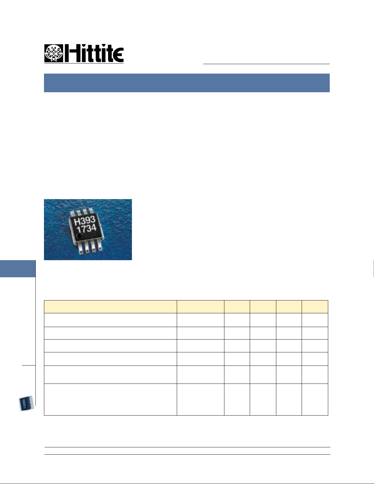
HMC393MS8G
GaAs MMIC DPDT DIVERSITY SWITCH 5.0 - 6.0 GHz
7
FEBRUARY 2001
Features
Low Insertion Loss: <1.2 dB @ 5.5 GHz
High IP3: 49 dBm
Positive Control: 0/+5V
Ultra Small MSOP8G Package: 14.8 mm
V00.0101
General Description
The HMC393MS8 is a low cost C-band
DPDT switch that operates between 5.0
and 6.0 GHz. This switch can operate as
an integrated antenna diversity and transmit/receive switch for the HyperLAN and
2
UNII radios platforms. The design provides 20 dB of isolation between antennas
and between Tx and Rx ports. The switch
features 1.2 dB insertion loss and high
power handling capability. Switch state is
controlled using four CMOS level control
voltage lines.
Guaranteed Performance Vctl = 0/ +5 Vdc, 50 Ohm System, -40 to +85 deg. C
retemaraP ycneuqerF .niM .pyT .xaM stinU
SWITCHES
DPDT
SMT
12 Elizabeth Drive, Chelmsford, MA 01824 Phone: 978-250-3343 Fax: 978-250-3373 Web Site: www.hittite.com
7 - 142
ssoLnoitresnI
noitalosI
)troPynA,etatSnO(ssoLnruteRzHG0.6-0.53102Bd
noisserpmoCBd1.0rofrewoPtupnIzHG0.6-0.57203mBd
tpecretnIredrOdrihTtupnI
)enoThcaEmBd22+=rewoPtupnIenoTowT(
scitsiretcarahCgnihctiwS
)FR%01/09/FR%09/01(LLAFt/ESIRt
)FR%09/01otLTC%05(FFOt/NOt
zHG0.6-0.52.10.2Bd
zHG0.6-0.55102Bd
zHG0.6-0.55494mBd
zHG0.6-0.5
11
22
Sn
Sn
Page 2
MICROWAVE CORPORATION
GaAs MMIC DPDT DIVERSITY SWITCH 5.0 - 6.0 GHz
new!
HMC393MS8G
'99
V00.0101
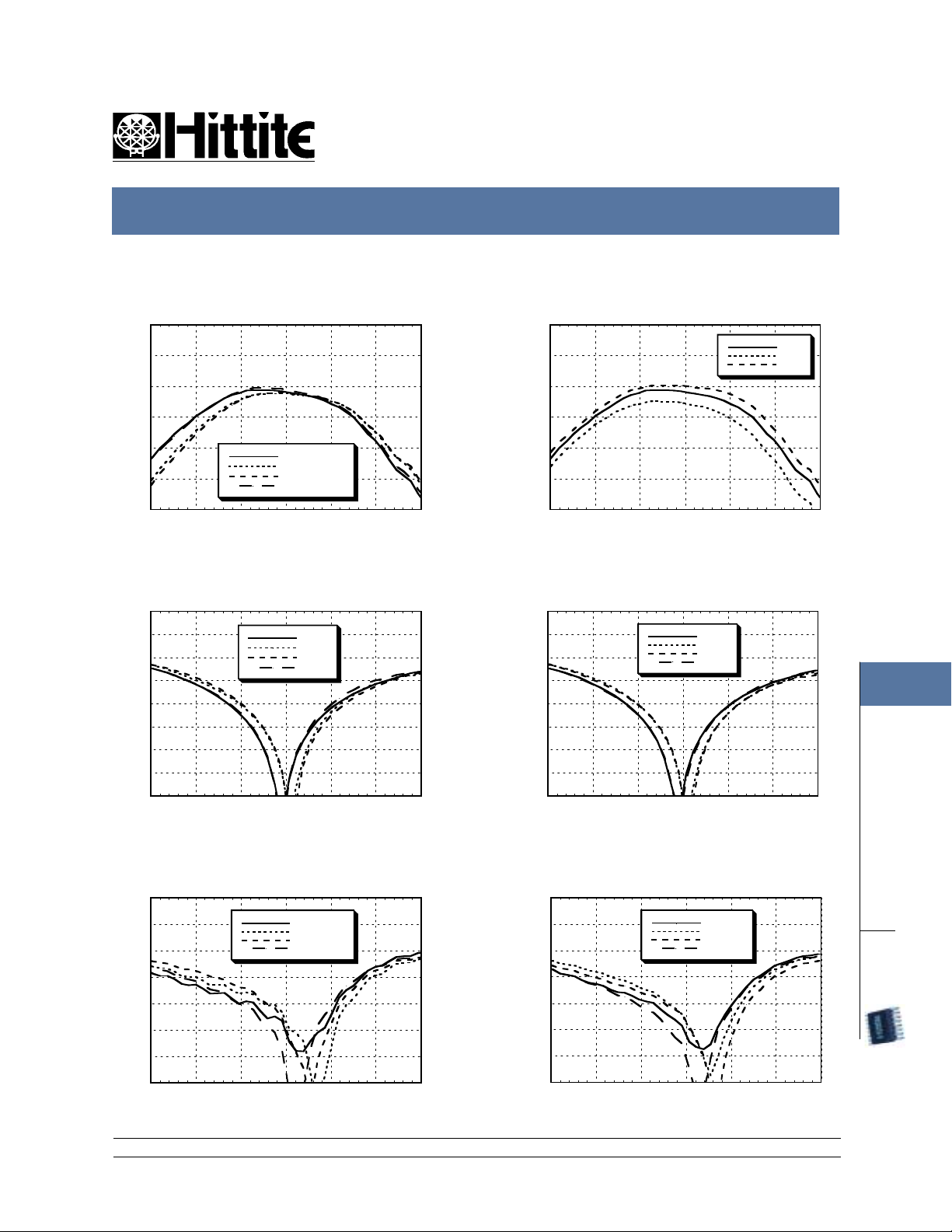
Insertion Loss
0
-0.5
-1
-1.5
-2
INSERTIONLOSS (dB)
-2.5
-3
44.555.566.57
ANT1-Tx State 1
ANT1-Rx State 2
ANT2-Tx State 3
ANT2-Rx State 4
FREQUENCY (GHz)
Insertion Loss vs. Temperature
0
-0.5
-1
-1.5
-2
INSERTIONLOSS (dB)
-2.5
-3
44.555.566.57
FREQUENCY (GHz)
Isolation, Tx & Rx Isolation, ANT1 & ANT2
0
-5
-10
-15
-20
-25
ISOLATION(dB)
-30
-35
-40
44.555.566.57
FREQUENCY (GHz)
State 1
State 2
State 3
State 4
0
-5
-10
-15
-20
-25
ISOLATION(dB)
-30
-35
-40
44.555.566.57
FREQUENCY (GHz)
State 1
State 2
State 3
State 4
FEBRUARY 2001
+25C
+85C
-40C
7
SWITCHES
Return Loss, ANT1 & ANT2
0
-5
-10
-15
-20
-25
RETURN LOSS (dB)
-30
-35
44.555.566.57
FREQUENCY (GHz)
ANT1 State 1
ANT1 State 2
ANT2 State 3
ANT2 State 4
Return Loss, Tx & Rx
0
-5
-10
-15
-20
-25
RETURN LOSS (dB)
-30
-35
44.555.566.57
FREQUENCY (GHz)
Tx State 1
Tx State 3
Rx State 2
Rx State 4
12 Elizabeth Drive, Chelmsford, MA 01824 Phone: 978-250-3343 Fax: 978-250-3373 Web Site: www.hittite.com
7 - 143
DPDT
SMT
Page 3

'99
new!
HMC393MS8G
MICROWAVE CORPORATION
GaAs MMIC DPDT DIVERSITY SWITCH 5.0 - 6.0 GHz
FEBRUARY 2001
Isolation, ANT1/ANT2 - Tx/Rx Input 0.1 dB Compression Point
0
-5
-10
-15
-20
ISOLATION(dB)
-25
-30
44.555.566.57
ANT1-Tx State 2
ANT1-Rx State 1
ANT2-Tx State 1
ANT2-Rx State 2
FREQUENCY (GHz)
35
34
33
32
31
30
29
28
27
0.1dB COMPRESSION ( dBm)
26
25
4.5 5 5.5 6 6.5
FREQUENCY (GHz)
V00.0101
+25C
+85C
-40C
Input IP3
7
SWITCHES
DPDT
SMT
55
54
53
52
51
50
49
IP3 (dBm)
48
47
46
45
4.5 5 5.5 6 6.5
FREQUENCY (GHz)
T ruth Table
htaP 1V 2V 3V 4V etatS
xT-1TNA hgiHwoLhgiHwoL1
xR-1TNA hgiHwoLwoLhgiH2
xT-2TNA woLhgiHhgiHwoL3
xR-2TNA woLhgiHwoLhgiH4
Control V oltages
etatS noitidnoCsaiB
woL.pyTAu3@cdV5.0+ot0
hgiH.pyTAu3@cdV5.6+ot0.5+
12 Elizabeth Drive, Chelmsford, MA 01824 Phone: 978-250-3343 Fax: 978-250-3373 Web Site: www.hittite.com
7 - 144
Page 4

MICROWAVE CORPORATION
GaAs MMIC DPDT DIVERSITY SWITCH 5.0 - 6.0 GHz
new!
HMC393MS8G
'99
V00.0101
Outline Drawing
FEBRUARY 2001
Absolute Maximum RatingsFunctional Diagram
V5+/0=ltcVrewoPtupnIFRmBd33+
)4V,3V,2V,1V(egnaRegatloVlortnoCcdV5.7+ot5.0-
erutarepmeTegarotSCged051+ot56-
erutarepmeTgnitarepOCced58+ot04-
Caution: Do not 'hot switch' power levels greater than
+23 dBm (VCTL= 0/+5 Vdc).
DC blocking capacitors are required at ports ANT1,
ANT2, Tx, Rx. Choose value for lowest frequency of
operation.
7
1. MATERIAL:
A) PACKAGE BODY - LOW STRESS INJECTION-MOLDED PLASTIC,
SILICA & SILICONE IMPREGNATED.
B) LEADFRAME MATERIAL: COPPER ALLOY
2 . PLATING : LEAD - TIN SOLDER PLATE
3. DIMENSIONS ARE IN INCHES (MILLIMETERS).
12 Elizabeth Drive, Chelmsford, MA 01824 Phone: 978-250-3343 Fax: 978-250-3373 Web Site: www.hittite.com
UNLESS OTHERWISE SPECIFIED ALL TOL. ARE ±0.005 (±0.13).
4. CHARACTERS TO BE HELVETICA MEDIUM, APPROX .020 HIGH
WHITE INK, LOCATED APPROXIMATELY AS SHOWN.
5. DIMENSION DOES NOT INCLUDE MOLDFLASH OF 0.15 MM PER SIDE
6. DIMENSION DOES NOT INCLUDE MOLDFLASH OF 0.25 MM PER SIDE
7 - 145
SWITCHES
DPDT
SMT
Page 5

'99
new!
MICROWAVE CORPORATION
GaAs MMIC DPDT DIVERSITY SWITCH 5.0 - 6.0 GHz
FEBRUARY 2001
Evaluation PCB for HMC393MS8G
HMC393MS8G
V00.0101
7
The circuit board used in the final application should use RF circuit design techniques. Signal lines should have
50 ohm impedance while the package ground leads and exposed paddle should be connected directly to the
ground plane similar to that shown above. A sufficient number of VIA holes should be used to connect the top
and bottom ground planes. The evaluation circuit board as shown is available from Hittite upon request.
SWITCHES
DPDT
SMT
* R1 & R2 = 100 Ω .
These optional resistors will
provide more RF path to control
circuit isolation.
List of Material
metI noitpircseD
4J-1JrotcennoCAMStnuoMCP
8J-5JniPCD
4C-1C ycneuqerftsewolrofeulavesoohC.gkP2040,roticapaCpihC
.BCPnodedivorpsiFp001.noitarepofo
2R-1R.gkP2040,retsiseRmho001
1UhctiwSytisreviDTDPDG8SM393CMH
*BCP"5.1x"5.1BCPnoitaulavE730301
0534sregoR:lairetaMdraoBtiucriC*
12 Elizabeth Drive, Chelmsford, MA 01824 Phone: 978-250-3343 Fax: 978-250-3373 Web Site: www.hittite.com
7 - 146
Page 6

MICROWAVE CORPORATION
GaAs MMIC DPDT DIVERSITY SWITCH 5.0 - 6.0 GHz
new!
HMC393MS8G
'99
V00.0101
NOTES:
FEBRUARY 2001
7
12 Elizabeth Drive, Chelmsford, MA 01824 Phone: 978-250-3343 Fax: 978-250-3373 Web Site: www.hittite.com
7 - 147
SWITCHES
DPDT
SMT
 Loading...