

Page 1
MICROWAVE CORPORATION
v00.0501
HMC365S8G
SMT GaAs HBT MMIC
DIVIDE-BY-4, DC - 13.0 GHz
3
Typical Applications
Prescaler for DC to Ku Band PLL Applications:
• Satellite Communication Systems
• Fiber Optic
• Pt-Pt and Pt-MPt Radios
• VSAT
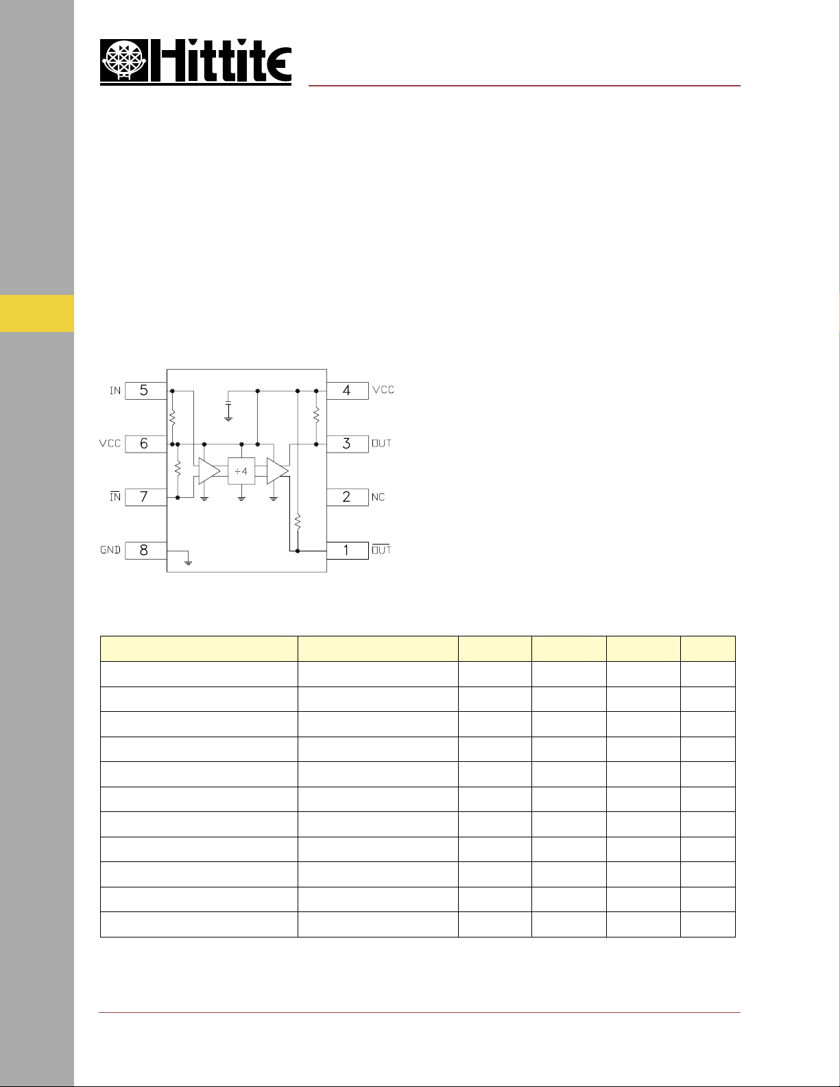
Functional Diagram
Features
Ultra Low SSB Phase Noise: -151 dBc/Hz
Wide Bandwidth
Output Power: 5 dBm
Single DC Supply: +5V
S8G SMT Package
General Description
The HMC365S8G is a low noise Divide-by-4
Static Divider with InGaP GaAs HBT technology
in an 8 lead surface mount plastic package. This
device operates from DC (with a square wave
input) to 13.0 GHz input frequency with a single
+5.0V DC supply. The low additive SSB phase
noise of -151 dBc/Hz at 100 kHz offset helps the
user maintain good system noise performance.
Guaranteed Performance, Vcc= 5V, 25 Deg °C
FREQ. DIVIDERS & DETECTORS - SMT
1. Divider will operate down to DC for square-wave input signal.
retemaraPsnoitidnoC.niM.pyT.xaMstinU
ycneuqerFtupnImumixaM 3141zHG
ycneuqerFtupnImuminiM]1[.tupnIevaWeniS2.05.0zHG
egnaRrewoPtupnIzHG8ot1=niF51-02->01+mBd
zHG11ot8=niF01-51->3+mBd
zHG31ot11=niF5-8->3+mBd
rewoPtuptuOzHG31=niF25mBd
egakaeLesreveRdetanimreTstuptuOFRhtoB54Bd
)tesffozHk001(esioNesahPBSSzHG6=niF,mBd0=niP151-zH/cBd
emiTnoitisnarTtuptuOzHM288=tuoF,mBd0=niP001sp
)ccV(egatloVylppuSdednemmoceR 0.5cdV
)ccI(tnerruCylppuS 511Am
3 - 66
For price, delivery, and to place orders, please contact Hittite Microwave Corporation:
12 Elizabeth Drive, Chelmsford, MA 01824 Phone: 978-250-3343 Fax: 978-250-3373
Visit us at www.hittite.com, or Email at sales@hittite.com
Page 2
v00.0501
HMC365S8G
MICROWAVE CORPORATION
SMT GaAs HBT MMIC
DIVIDE-BY-4, DC - 13.0 GHz
GaAs MMIC SUB-HARMONICALLY PUMPED MIXER 17 - 25 GHz
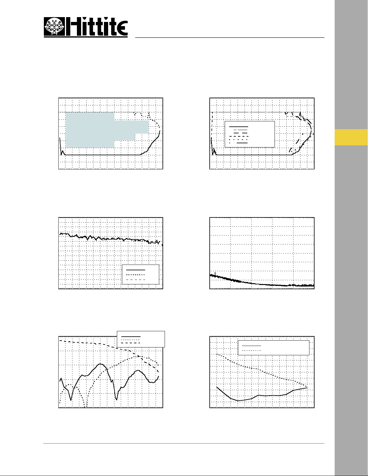
Input Sensitivity Window, T= 25 °C Input Sensitivity Window vs. Temperature
20
10
0
Recommended
Operating Window
-10
INPUT POWER (dBm)
-20
-30
0 1 2 3 4 5 6 7 8 9 10 11 12 13 14 15
INPUT FREQUENCY (GHz)
Output Power vs. Temperature
10
9
8
7
6
5
4
3
2
1
0
-1
OUTPUT POWER (dBm)
-2
-3
-4
-5
0 1 2 3 4 5 6 7 8 9 10 11 12 13 14 15
INPUT FREQUENCY (GHz)
+25 C
+85 C
-40 C
20
10
0
-10
INPUT POWER (dBm)
-20
-30
0 1 2 3 4 5 6 7 8 9 10 11 12 13 14 15
Min Pin +25 C
Max Pin +25 C
Min Pin +85 C
Max Pin +85 C
Min Pin -40 C
Max Pin -40 C
INPUT FREQUENCY (GHz)
SSB Phase Noise
Performance, Pin= 0 dBm, T= 25 °C
0
-20
-40
-60
-80
-100
-120
SSB PHASE NOISE (dBc/Hz)
-140
-160
2
10
3
10
4
10
OFFSET FREQUENCY (Hz)
5
10
3
6
10
7
10
Output Harmonic
Content, Pin= 0 dBm, T= 25 °C
0
-10
-20
-30
OUTPUT LEVEL (dBm)
-40
-50
0 1 2 3 4 5 6 7 8 9 10 11 12 13 14 15
INPUT FREQUENCY (GHz)
For price, delivery, and to place orders, please contact Hittite Microwave Corporation:
12 Elizabeth Drive, Chelmsford, MA 01824 Phone: 978-250-3343 Fax: 978-250-3373
Visit us at www.hittite.com, or Email at sales@hittite.com
Pfeedthru
2nd Harmonic
3rd Harmonic
Reverse Leakage, Pin= 0 dBm, T= 25 °C
0
-10
-20
-30
-40
POWER LEVEL (dBm)
-50
-60
0 1 2 3 4 5 6 7 8 9 10 11 12 13 14 15
INPUT FREQUENCY (GHz)
Both Output Ports Terminated
One Output Port Terminated
FREQ. DIVIDERS & DETECTORS - SMT
3 - 67
Page 3

MICROWAVE CORPORATION
v00.0501
Output V oltage Wavef orm,
Pin= 0 dBm, Pout= 882 MHz, T= 25 °C
HMC365S8G
SMT GaAs HBT MMIC
DIVIDE-BY-4, DC - 13.0 GHz
Absolute Maximum Ratings
3
700
600
500
400
300
200
100
0
-100
-200
AMPLITUDE (mV)
-300
-400
-500
-600
-700
22.7 22.9 23.1 23.3 23.5 23.7 23.9 24.1 24.3 24.5 24.7
TIME (nS)
Pin Locations & Outline Drawing
)V5+=ccV(tupnIFRmBd31+
ccVV5.5+
cigoLVV2.1-ccVotV6.1-ccV
erutarepmeTegarotSCged051+ot56-
erutarepmeTgnitarepOCged58+ot55-
FREQ. DIVIDERS & DETECTORS - SMT
3 - 68
1. MA TERIAL:
A. PACKAGE BODY - LOW STRESS INJECTION -MOLDED PLASTIC,
SILICA & SILICONE INPREGNATED.
B. LEADFRAME MATERIAL: COPPER ALLOY
2. PLATING: LEAD-TIN SOLDER PLATE
3. DIMENSIONS ARE IN INCHES (MILLIMETERS)
4. CHARACTERS TO BE HELVETICA MEDIUM, .030 HIGH USING WHITE
INK, LOCATED APPROX AS SHOWN
5. DIMENSION DOES NOT INCLUDE MOLDFLASH OF 0.15mm PER SIDE.
6. DIMENSION DOES NOT INCLUDE MOLDFLASH OF 0.25mm PER SIDE.
For price, delivery, and to place orders, please contact Hittite Microwave Corporation:
12 Elizabeth Drive, Chelmsford, MA 01824 Phone: 978-250-3343 Fax: 978-250-3373
Visit us at www.hittite.com, or Email at sales@hittite.com
Page 4

MICROWAVE CORPORATION
v00.0501
Pin Description
rebmuNniPnoitcnuFnoitpircseDcitamehcSecafretnI
1TUO.3niphtiwesahpfotuo°081tuptuodediviD
2C/N.noitcennocoN
HMC365S8G
SMT GaAs HBT MMIC
DIVIDE-BY-4, DC - 13.0 GHz
3
3TUO
4CCV
5NI.dekcolbCDebtsumtupnIFR
6CCV .6ro4nipotdeilppaebnacV52.0±V5egatlovylppuS
.tuptuOdediviD
.6ro4nipotdeilppaebnacV52.0±V5egatlovylppuS
FREQ. DIVIDERS & DETECTORS - SMT
7NI
8DNG
For price, delivery, and to place orders, please contact Hittite Microwave Corporation:
12 Elizabeth Drive, Chelmsford, MA 01824 Phone: 978-250-3343 Fax: 978-250-3373
Visit us at www.hittite.com, or Email at sales@hittite.com
.noitarepodedneelgnisrofdnuorg
.dnuorgotdetcennocebtsum
CA.noitarepolaitnereffidrof5niphtiwesahpfotuo°081tupnIFR
hcihwgulsdnuorglatemdesopxesahegakcapfoediskcaB:dnuorG
3 - 69
Page 5

3
MICROWAVE CORPORATION
v00.0501
HMC365S8G Evaluation PCB
HMC365S8G
SMT GaAs HBT MMIC
DIVIDE-BY-4, DC - 13.0 GHz
The circuit board used in the final application should use RF circuit design techniques. Signal lines should
have 50 ohm impedance while the package ground leads and backside ground slug should be connected
directly to the ground plane similar to that shown. A sufficient number of via holes should be used to connect the top and bottom ground planes. The evaluation circuit board shown is available from Hittite upon
request. This evaluation board is designed for single ended input testing. J2 and J3 provide differential
output signals.
Evaluation Circuit Board Layout Design Details
metInoitpircseD
3J-1JrotcennoCFRAMStnuoMCP
FREQ. DIVIDERS & DETECTORS - SMT
4C-1C.gkP2040,roticapaCFp001
5C.gkP3060,roticapaCFp0001
6CroticapaCmulatnaTFµ01
1U4-yb-ediviDG8S563CMH
*BCPdraoBlavE726401
0534sregoR:lairetaMdraoBtiucriC*
3 - 70
For price, delivery, and to place orders, please contact Hittite Microwave Corporation:
12 Elizabeth Drive, Chelmsford, MA 01824 Phone: 978-250-3343 Fax: 978-250-3373
Visit us at www.hittite.com, or Email at sales@hittite.com
Page 6

MICROWAVE CORPORATION
v00.0501
HMC365S8G Application Schematic
HMC365S8G
SMT GaAs HBT MMIC
DIVIDE-BY-4, DC - 13.0 GHz
3
For price, delivery, and to place orders, please contact Hittite Microwave Corporation:
12 Elizabeth Drive, Chelmsford, MA 01824 Phone: 978-250-3343 Fax: 978-250-3373
Visit us at www.hittite.com, or Email at sales@hittite.com
FREQ. DIVIDERS & DETECTORS - SMT
3 - 71
 Loading...