

Page 1
General Description
L
C
U
DM8108
8 port 10/100M Fast Ethernet Swit ching Control ler
The DM8108 is an 8 port 10/100Mbit/s nonblocking
Ethernet switch with on-chip address-lookup engine. The
DM8108 provides a low-cost, high-performance switch
solution with PHYs and single SGRAM.
The DM8108 provides eight 10/100Mbit/s Fast Ethernet
interface. In half-duplex mode, all ports support backpressure capability to reduce the risk of data loss for a long
burst of activity. In the full-duplex mode of operation, the
device uses IEEE std. 802.3 frame-based pause protocol
for flow control. With full-duplex capability, port 0 – 7 s upport
1.6Gbit/s aggregate bandwidth connections. The DM8108
also supports port trunking/load balancing on the
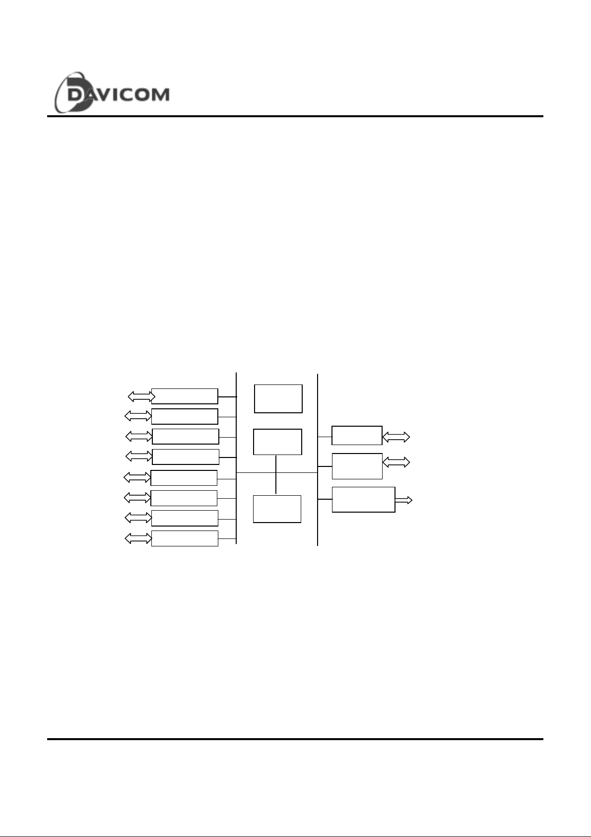
Block Diagram
Contro l &
Status
Address
earning
10/100Mbit ports. This can be used to group ports on interswitch links to increase the effective bandwidth between the
systems.
The internal address-lookup engine supports up to 16.25K
unicast and unlimited multica st and broadc ast addresses.
This engine performs destination and source addresses
book-keeping and comparison which also forwards
unknown destination address packets to all ports.
The DM8108 is fabricated with a .35um technology.
Working at 3.3V, the inputs are 5V to le ran t and the outputs
are capable of directly driving at TTL leve ls.
Expansion
MEM
ontroller
Switching
Engine
LED Control
nit
Preliminary 1
Version: DM8108-DS-P02
November 25, 1999
Page 2

Features
T
Low cost Fast Ethernet Switching Controller.
O Provide packet switching functions between
eight
10/100Mbps, auto-negotiated on-chip Fast
Ethernet ports and a proprietary Full-duplex
Expansion port.
O Cascade max. 8 DM8108s without extra glue
logic for 64-port configuration.
T
Incorporates three 802.3 compliant 10/100Mbps
Media Access Controllers
O Direct interface to MII (Media Independent
Interface)
O Half/Full Duplex Support for individual port (upto
200Mbps/port)
O IEEE 802.3 100Base-TX, T4.FX compatible
T
Auto-negotiation supported through Serial MII
interface
T
High-performance Distributed Switching Engine
O Performs packet forwarding and filtering at full
wire-speed
O 148,800 packets/sec. on each Ethernet port
T
Direct support for packet buffering
O Glue-less interface with 1 or 2 Mbytes of SDRAM
(SGRAM)
O 32 bit memory bus configuration
O 66 Mhz – 90Mhz memory bus speed
O Up-to 1.1K buffers, 1536-byte each, allocated to
receive ports
T
Support Store and Forward switching approach
DM8108
8 port 10/100M Fast Ethernet Swit ching Control ler
O Low last-bit to first-bit out del ay
O Allow mixed speed Ethernet packet switching
O Allow conversion between different protocols
T
Flow control
O Support partitioning function
O Support back-pressure while lack of internal
resources
O Support 802.3x PAUSE function in full duplex
mode
O Support up to 4-port trunking for 800Mbps
bandwidth
T
Advanced Address Learning and Searching
O Self learning mechanism
O Cache 128 address entries internally
O Record up-to 16K Uni-cast MAC addresses and
unlimited Multicast and Broadcast addresses
O Automatic aging scheme
O Broadcast filtering rate control
T
Expansion Bus
O Up-to 8 SW devices can be cascaded via
expansion bus without extra logic
O Full duplex mode transfer
O Less Bus overhead
O Automatic flow control
T
Complete status report to a simple LED interface
T
Suitabl e for low cost Switc h market to replace
Hub
T
0.35m process, 3. 3V wit h 5V tolerant I/O
T
208-pin PQFP package
2 Preliminary
Version: DM8108-DS-P02
November 25, 1999
Page 3
8 port 10/100M Fast Ethernet Swit ching Control ler
r
r
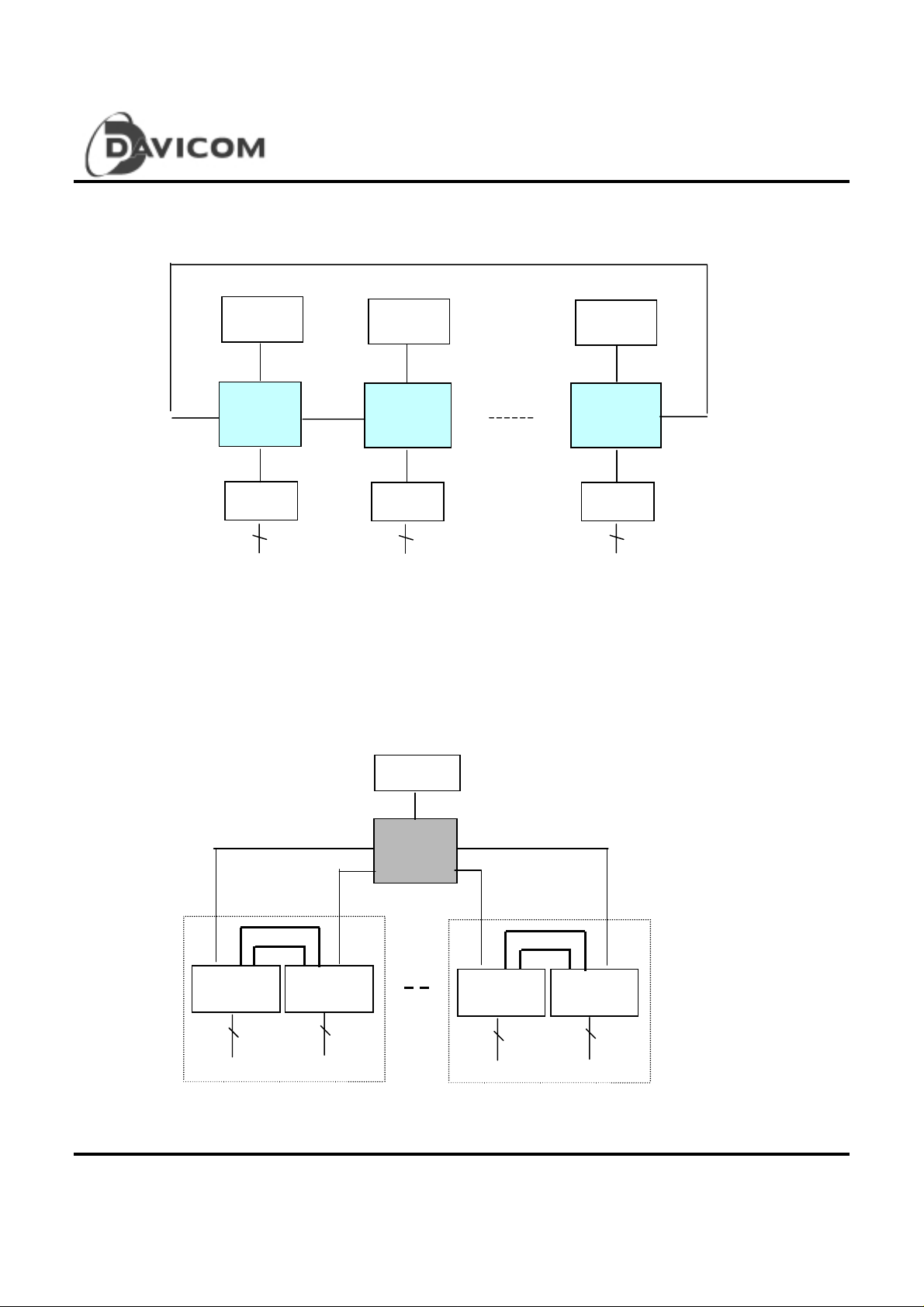
Applica tion Example: Low cost 8 to 64 ports 10/100 Mbps auto-sensing switch
DM8108
MEM
DM8108
PHY
8 8
8
MEM
DM8108
PHY
MEM
DM8108
PHY
Applica tion Exa mple : Low cost auto-sens ing switc hing hub implementation
Cascaded up-to 64 10/100Mbps Fast Ethernet ports
10/100 BaseTx
MEM
MII MII
#1 Hub Module #4 Hub Module
10/100 BaseTx
Preliminary 3
Version: DM8108-DS-P02
November 25, 1999
PHY with
PHY with
DM8108
PHY with
epeater
PHY with
epeater
Page 4

8 port 10/100M Fast Ethernet Swit ching Control ler
High density mixed switching and hub ports with 8 collision domains
DM8108
4 Preliminary
Version: DM8108-DS-P02
November 25, 1999
Page 5

Pin Configuration
DM8108
8 port 10/100M Fast Ethernet Swit ching Control ler
VSS
LEDCLK
LEDSTB
LEDD
RST#
TESTEN
VSS
RXER0
RXDV0
COL0
CRS0
RXCLK0
RXD0[0]
RXD0[1]
RXD0[2]
RXD0[3]
TXCLK0
TXEN0
TXD0[0]
TXD0[1]
TXD0[2]
TXD0[3]
VDD
RXER1
RXDV1
COL1
CRS1
RXCLK1
RXD1[0]
RXD1[1]
RXD1[2]
RXD1[3]
TXCLK1
TXEN1
TXD1[0]
TXD1[1]
TXD1[2]
TXD1[3]
VSS
RXER2
RXDV2
COL2
CRS2
RXCLK2
RXD2[0]
RXD2[1]
RXD2[2]
RXD2[3]
TXCLK2
TXEN2
TXD2[0]
TXD2[1]
RXCLK8
VSS
TXD8[3]
TXD8[2]
TXD8[1]
TXD8[0]
202
201
200
199
VDD
198
RXD8[0]
RXD8[2]
RXD8[1]
RXD8[3]
203
204
205
206
207
208
1
2
3
4
5
6
7
8
9
10
11
12
13
14
15
16
17
18
19
20
21
22
23
24
25
26
27
28
29
30
31
32
33
34
35
36
37
38
39
40
41
42
43
44
45
46
47
48
49
50
51
52
5355545657585960616263646566676869707172737475767778798081828384858687888990919293949596979899
TXCLK8
VSS
DMA0
195
196
197
DMA2
DMA1
DMA3
DMA4
VSS
DMA5
189
190
191
192
193
194
DM8108
DMA6
DMA7
187
188
DMA8
VDD
185
186
DMA9
SBA
183
184
DWE#
VSS
SDDQM#
180
181
182
SDCS#
CAS#
178
179
VSS
RAS#
176
177
SCLK
VSS
174
175
DMD0
DMD1
172
173
DMD3
DMD2
170
171
DMD4
DMD5
168
169
DMD6
DMD7
166
167
VSS
165
DMD9
DMD8
163
164
DMD11
DMD10
DMD12
160
161
162
100
101
DMD15
DMD14
DMD13
158
159
156
155
154
153
152
151
150
149
148
147
146
145
144
143
142
141
140
139
138
137
136
135
134
133
132
131
130
129
128
127
126
125
124
123
122
121
120
119
118
117
116
115
114
113
112
111
110
109
108
107
106
105
102
103
104
157
VDD
DMD16
DMD17
DMD18
DMD19
DMD20
DMD21
DMD22
DMD23
VSS
DMD24
DMD25
DMD26
DMD27
DMD28
DMD29
DMD30
DMD31
VSS
TXD7[3]
TXD7[2]
TXD7[1]
TXD7[0]
TXEN7
TXCLK7
RXD7[3]
RXD7[2]
RXD7[1]
RXD7[0]
RXCLK7
CRS7
COL7
RXDV7
RXER7
VDD
TXD6[3]
TXD6[2]
TXD6[1]
TXD6[0]
TXEN6
TXCLK6
RXD6[3]
RXD6[2]
RXD6[1]
RXD6[0]
RXCLK6
CRS6
COL6
RXDV6
RXER6
VSS
TXD5[3]
VDD
TXD2[2]
TXD2[3]
COL3
RXER3
RXDV3
CRS3
RXCLK3
RXD3[2]
RXD3[0]
RXD3[1]
TXEN3
RXD3[3]
TXCLK3
TXD3[1]
TXD3[0]
TXD3[2]
TXD3[3]
MIID
MIICLK
RXER4
RXDV4
COL4
CRS4
RXD4[1]
RXD4[0]
RXCLK4
RXD4[2]
TXCLK4
RXD4[3]
TXEN4
TXD4[0]
TXD4[1]
TXD4[3]
TXD4[2]
VDD
RXER5
COL5
RXDV5
CRS5
RXCLK5
RXD5[0]
RXD5[2]
RXD5[1]
TXEN5
RXD5[3]
TXCLK5
TXD5[0]
TXD5[1]
TXD5[2]
VSS
VSS
Preliminary 5
Version: DM8108-DS-P02
November 25, 1999
Page 6

DM8108
8 port 10/100M Fast Ethernet Swit ching Control ler
Pin Description
Pin Ass ignme nt
# NAME # NAME # NAME # NAME # NAME
1 VSS 43 CRS2 85 TXEN4 127 RXCLK7 169 MD(4)
2 LEDCLK 44 RXCLK2 86 TXD4(0) 128 RXD7(0) 170 MD(3)
3 LEDSTB 45 RXD2(0) 87 TXD4(1) 129 RXD7(1) 171 MD(2)
4 LEDD 46 RXD2(1) 88 TXD4(2) 130 RXD7(2) 172 MD(1)
5 RST* 47 RXD2(2) 89 TXD4(3) 131 RXD7(3) 173 MD(0)
6 TESTEN* 48 RXD2(3) 90 VDD 132 TXCLK7 174 VSS
7 VSS 49 TXCLK2 91 RXER5 133 TXEN7 175 SCLK
8 RXER0 50 TXEN2 92 RXDV5 134 TXD7(0) 176 VSS
9 RXDV0 51 TXD2(0) 93 COL5 135 TXD7(1) 177 SRAS*
10 COL0 52 TXD2(1) 94 CRS5 136 TXD7(2) 178 SDCAS*
11 CRS0 53 TXD2(2) 95 RXCLK5 137 TXD7(3) 179 SDCS*
12 RXCLK0 54 TXD2(3) 96 RXD5(0) 138 VSS 180 SDWE*
13 RXD0(0) 55 VDD 97 RXD5(1) 139 MD(31) 181 VSS
14 RXD0(1) 56 RXER3 98 RXD5(2) 140 MD(30) 182 SDQM*
15 RXD0(2) 57 RXDV3 99 RXD5(3) 141 MD(29) 183 MA(10) – SBA
16 RXD0(3) 58 COL3 100 TXCLK5 142 MD(28) 184 MA(9)
17 TXCLK0 59 CRS3 101 TXEN5 143 MD(27) 185 VDD
18 TXEN0 60 RXCLK3 102 TXD5(0) 144 MD(26) 186 MA(8)
19 TXD0(0) 61 RXD3(0) 103 TXD5(1) 145 MD(25) 187 MA(7)
20 TXD0(1) 62 RXD3(1) 104 TXD5(2) 146 MD(24) 188 MA(6)
21 TXD0(2) 63 RXD3(2) 105 TXD5(3) 147 VSS 189 MA(5)
22 TXD0(3) 64 RXD3(3) 106 VSS 148 MD(23) 190 VSS
23 VDD 65 TXCLK3 107 RXER6 149 MD(22) 191 MA(4)
24 RXER1 66 TXEN3 108 RXDV6 150 MD(21) 192 MA(3)
25 RXDV1 67 TXD3(0) 109 COL6 151 MD(20) 193 MA(2)
26 COL1 68 TXD3(1) 110 CRS6 152 MD(19) 194 MA(1)
27 CRS1 69 TXD3(2) 111 RXCLK6 153 MD(18) 195 MA(0)
28 RXCLK1 70 TXD3(3) 112 RXD6(0) 154 MD(17) 196 VSS
29 RXD1(0) 71 VSS 113 RXD6(1) 155 MD(16) 197 TXENCLK
30 RXD1(1) 72 MDCLK 114 RXD6(2) 156 VDD 198 VDD
31 RXD1(2) 73 MDIO 115 RXD6(3) 157 MD(15) 199 TXD8(0)
32 RXD1(3) 74 VSS 116 TXCLK6 158 MD(14) 200 TXD8(1)
33 TXCLK1 75 RXER4 117 TXEN6 159 MD(13) 201 TXD8(2)
34 TXEN1 76 RXDV4 118 TXD6(0) 160 MD(12) 202 TXD8(3)
35 TXD1(0) 77 COL4 119 TXD6(1) 161 MD(11) 203 VSS
36 TXD1(1) 78 CRS4 120 TXD6(2) 162 MD(10) 204 RXDVCLK
37 TXD1(2) 79 RXCLK4 121 TXD6(3) 163 MD(9) 205 RXD8(0)
38 TXD1(3) 80 RXD4(0) 122 VDD 164 MD(8) 206 RXD8(1)
39 VSS 81 RXD4(1) 123 RXER7 165 VSS 207 RXD8(2)
40 RXER2 82 RXD4(2) 124 RXDV7 166 MD(7) 208 RXD8(3)
41 RXDV2 83 RXD4(3) 125 COL7 167 MD(6)
42 COL2 84 TXCLK1 126 CRS7 168 MD(5)
6 Preliminary
Version: DM8108-DS-P02
November 25, 1999
Page 7

DM8108
8 port 10/100M Fast Ethernet Swit ching Control ler
Pin Description
Please refer to the “Strap pin default value after reset section” for the detail description of the
Strap pins.
DRAM Interfac e
Pin No. Pin Name I/O Description
139 – 146,
148 – 155,
157 – 164,
166 – 173
183 – 184,
186 – 189,
191 – 195
177 SRAS* O Row address strobe for SDRAM
178 SDCAS* O Column address strobe for SDRAM
180 SDWE* O Write cycle indication, internally pulled up
182 SDQM O Data Mask f or SDRAM
179 SDCS* O Chip select for SDRAM
Expansion B us
(continued)
MD(31:0) I/O DRAM data lines 31 – 0
MA(10:0) I/O DRAM address lines 10-0; strap pins during reset
MA9: 0= enable limit4, 1=disbale limit 4
MA8: DRAM size selection; 0= 1M, 1=2M
MA7-0: Auto-negotiation enable for port 7-0; 0= enabled
Pin No. Pin Name I/O Description
204 RXDVCLK I/O Expansion port’s receiving data valid
208 – 205 RXD8[3:0] I/O Expansion port’s receive data input
197 TXENCLK I/O Expansion port’s transmit enable output
202 – 199 TXD8[3:0] I/O Expansion port’s transmit data output
Strap pins during reset:
TXD8[2:0] = device # setting
TXD8[3] = dram timi ng
LED Interface
Pin No. Pin Name I/O Description
2 LEDCLK O LED data clock
4 LEDD O LED data: active low. Data stream that contains LED indicators per
port. The data is shifted out and should be qualified by LDSTB* to
clock into ext er nal regi st er s to driv e L EDs.
Strap pin during re set:
0: expansion port with fast speed
1: expansion port with lower apees
3 LDSTB I/O LED data strobe: active high. Used to strobe the LD into an external
register
Strap pin during re set:
0: force link
1: link detection through serial MII
Preliminary 7
Version: DM8108-DS-P02
November 25, 1999
Page 8

8 port 10/100M Fast Ethernet Swit ching Control ler
MII Interfa ce
Pi n No. Pin Name I/O Description
133,117,101,
85,66,50,34,18
132,116,100,84,
65,49,33,17
22 – 19 TXD0(3:0) B Transmit data for port 0; synchronous to TXCLK0.
38 – 36 TXD1(3:0) B Transmit data for port 1; synchronous to TXCLK1.
54 – 51 TXD2(3:0) B Transmit data for port 2; synchronous to TXCLK2.
70 – 67 TXD3(3:0) B Transmit data for port 3; synchronous to TXCLK3.
89 – 86 TXD4(3:0) O Transmit data for port 4; synchronous to TXCLK4.
105 –102 TXD5(3:0) O Transmit data for port 5; synchronous to TXCLK5.
121 –118 TXD6(3:0) O Transmit data for port 6; synchronous to TXCLK6.
137 –134 TXD7(3:0) O Transmit data for port 7; synchronous to TXCLK7.
16 – 13 RXD0(3:0) I Receive data for port 0; synchronous to RXCLK0.
32 – 29 RXD1(3:0) I Receive data for port 1; synchronous to RXCLK1.
48 – 45 RXD2(3:0) I Receive data for port 2; synchronous to RXCLK2.
64 – 61 RXD3(3:0) I Receive data for port 3; synchronous to RXCLK3.
83 – 80 RXD4(3:0) I Receive data for port 4; synchronous to RXCLK4.
TXEN(7:0) B Transmi t Enabl e: Activ e high , synchronous to TXCLK; indicate that
the transmission data is valid.
Strap function during reset-TXEN(7:0): 0 = port 7-0 full duplex
TXCLK(7:0) I Transmit Clock: Provides the timing reference for the transfer of
TXEN, TXD signals. It is 25MHz for 100Mbps and 2.5MHz for
10Mbps.
Strap function during reset-TDX0[0]: 0=80Mhz, 1=66Mhz CLOCK operation
TXD0[1]: 0=enable partition mode, 1=disable partition mode
TXD0[2]: 0=enable expansion por t, 1=disa ble e xpansion port
TXD0[3]: 0=init only, 1= enable BIST
Strap function during reset -TXD1[2 :0]: te st mod e
TXD1[3]: 0=enable CRC, 1=disbale CRC
Strap function during reset -TXD2[2:0]: device # setting
TXD2 [3]: DRAM timing 0=fa st, 1= slo w
Strap function during reset -TXD3[0]: 0=max. packet size 1536, 1=max. packet size 1518(default)
TXD3[1]: 0=enable back_pressure, 1= disable (default)
TXD3[3:2]: age strap pins
00= 64 sec. 01= 128 sec.
10= 256 sec. 11= disbale
Strap function during reset –
TXD4[0]: 0= port 0 trunking enable 1= port 0 no trunking (default)
TXD4[1]: 0= port 1 trunking enable 1= port 1 no trunking (default)
TXD4[2]: 0= port 2 trunking enable 1= port 2 no trunking (default)
TXD4[3]: 0= port 3 trunking enable 1= port 3 no trunking (default)
Strap function during reset –
TXD5[1:0]: br oadcast f iltering rate selection
00 = 8k/sec 01 = 16k/sec
10 = 64k/sec 11= disable
DM8108
8 Preliminary
Version: DM8108-DS-P02
November 25, 1999
Page 9

DM8108
8 port 10/100M Fast Ethernet Swit ching Control ler
99 – 96 RXD5(3:0) I Receive data for port 5; synchronous to RXCLK5.
115 - 112 RXD6(3:0) I Receive data for port 6; synchronous to RXCLK6.
137 - 128 RXD7(3:0) I Receive data for port 7; synchronous to RXCLK7.
127,111,95,79,
60,44,28,12
124,108,92,76,
57,41,25,9
123,107,91,75,
56,40,24,8
126,110,94,78,
59,43,27,11
125,109,93,77,
58,42,26,10
72 MDCLK I/O Serial MII management interface clock signal: 1MHz clock for MDIO
73 MDIO I/O Serial MII management interface data; this bi-direction line is used to
RXCLK(7:0) I Receive clock for port 7 – 0; synchronous to RXD, RXDV,RXER; has
same clock rate as TXCLK.
RXDV(7:0) I Receive data valid indication for port 7 – 0.
RXER(7:0) I Receive data error indication for port 7 – 0.
CRS(7:0) I Carri er sense; acti ve high. Ind icates that either the tra n smit or
receive medium is not Idle. CRS is not synchronous to any clock.
COL( 7:0 ) I C ollis ion De tect ; active high. Indicates a collision has been detected
on the wire.
This input is ignored during full duplex operation and in the half duplex
mode while TXEN of the same port is low.
data reference. Connected to all PHY ports; It is an input pin if t he
device # is not 0 in SDRAM mode; else, it is an output pin.
transfer control Information and status between the PHY and the
DM8108. It conforms to the IEEE-802.3 specifications.
This signal may be connected to the PHY devices of all ports.
Pulled down if not used.
Miscellaneous Interface pins
Pin No. Pin Name I/O Descriptio n
175
5
6
Power pins
Pin No. Pin Name I/O Description
23,55,90,122,
156,185,198
1,7,39,71,74,
106,138,147,
165,174,176,
181,190,196,
203
SCLK
RST*
TESTEN*
VCC
GND
I
Memory clock: used by the DRAM state machine.
I
Reset signal for the chip.
I
Test pin to enable test functions
Power
Ground Connected to Ground plane
Connected to 3.3V Power plane
Preliminary 9
Version: DM8108-DS-P02
November 25, 1999
Page 10
o
Functional Description
M
DM8108
8 port 10/100M Fast Ethernet Swit ching Control ler
Fast Ethe rnet P orts Functiona l Overv iew
The DM8108 is a high-performance, low-cost Fast
Ethernet Switching Controller which provides packet
switching between eight on-chip, 10/100 Mbps ports
and one optional expansion port. It is suitable for the
auto-sensing 10/100Mbps switch application.
Switching Architecture
The switching architecture is based on the shared memory
and handshaking signals to swi tch pack ets between on-chip
ports hard-wired.
For an incoming packet, the receiving port’s MA C s to r es i t in
the receiv ing buff ers if it i s a good packet. At the same
time, the switching engine determines which port the packet
will forward to and update the address table which will be
used for future packet forwarding reference.
Fast Ethernet Ports
The DM8108 integrates eight Fast Ethernet ports, working
at 10/100Mbps (half-duplex) or 20/200Mbps (full-duplex)
with of f-the-shelf PHY chips. The inte rface is glu e-less
through Media Independent Interfaces (MII). The autonegotiation function determines the port’s operating mode.
With auto-negotiation disabled, the po r ts can be forced to
operate at a certain mode, if so desi red. Each port i n c ludes
the Media Access Control function (MAC), LED signals for
Link, Co llis io n, R e ce ive/Tra ns mit, Ha lf/Full duplex and
Rece ive Bu ffer Full indica tio ns .
Address Recognition
The DM8108 in a system can recognize up t o 1 6K Uni -c ast
MAC addresses and unlimited Multica s t/ Broadca st MAC
addresses. An intelligent address recognition mechanism
enables filtering and forwarding packets at full Ethernet wire
speed. The DM8108 provides an address self-learning
mechanism. As each DM8108 learns new address, it
updates the address table in the storage.
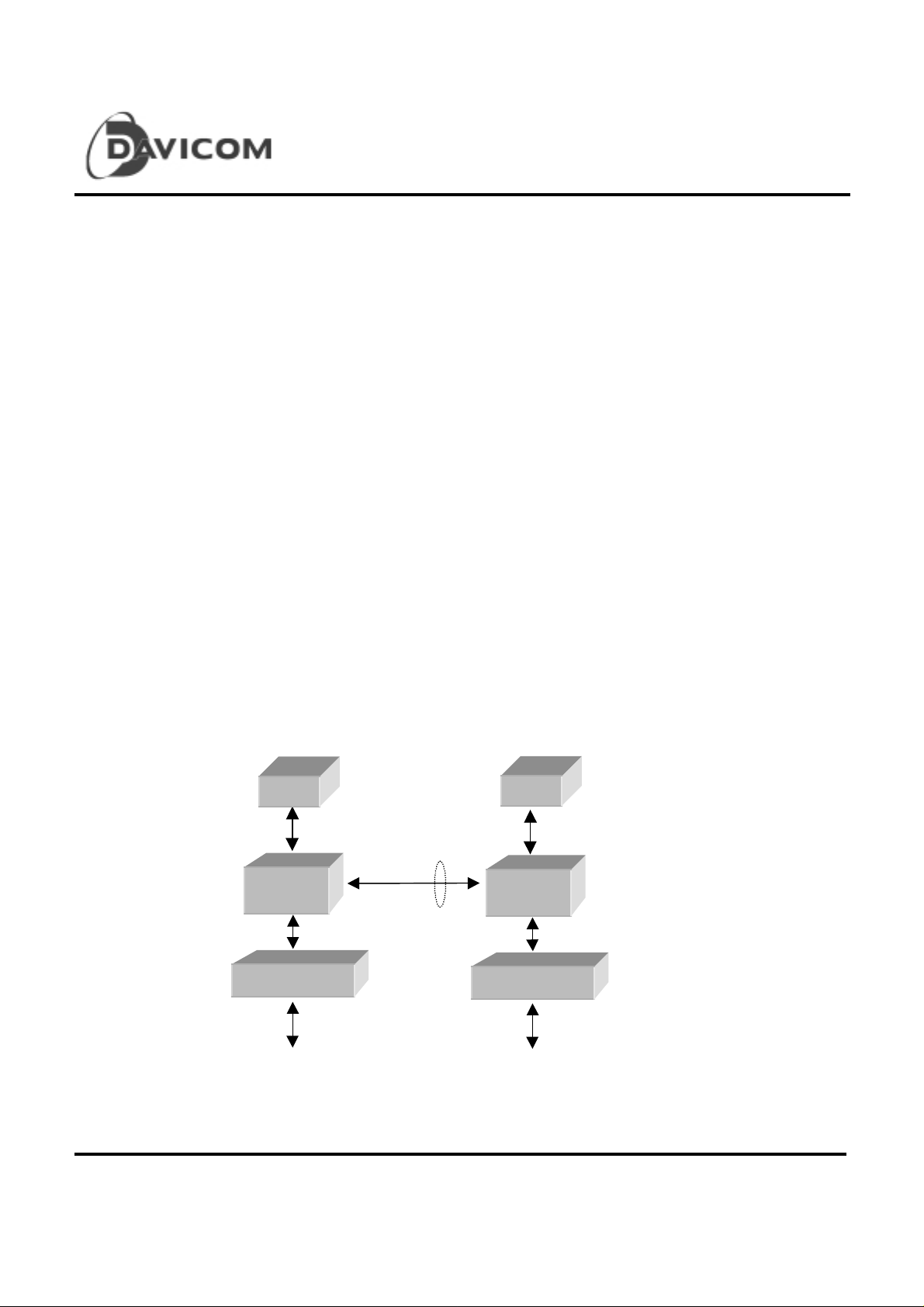
Fig.1: Typical 10/100 Mbps auto-sensing switching hub application
EM
ptional
DM8108
10/100 Mbps PHY
MEM
DM8108
10/100 Mbps PHY
Switch Ports Switch Ports
10 Preliminary
Version: DM8108-DS-P02
November 25, 1999
Page 11

DM8108
8 port 10/100M Fast Ethernet Swit ching Control ler
Packet Routing
As any port in the DM8108 receives a packet, the DM8108
will p ut th e re ce ived data in the receiving buffer and start the
address recognition at same time.
1. If the destination address is pointed to a local port
other than receiving port, the DM8108 will update the
Transmit Descriptor of the target port with the buffer
location and byte count information and wait for
transmission.
2. If the destination address is pointed to a port located in
other devices, the DM8108 will update the
Transmit Descriptor of the expansion port with the
receiving buffer location and byte count information
and wait for transmission.
3. I
f the destination address is not found in the Address
Table, the DM8108 will update all the Transmit
De s cr ip to r s , exc e pt th e one of t he r ec eivi ng port, for
transmission.
4. For the Multicast/Broadcast addresses, the DM8108
simply updates all the Transmit Descriptors, except
the one of th e re ceiv i ng p o rt or t h e ports that are
disabled, for Transmission.
5. For bad packet, the DM8108 simply discards it.
6. If the receiving buffer or the Transmit Descriptor for a
particular port is full, the packet will be lost.
The DM8108 is targeted for the non-managed Ethernet
Switching application. No management functions provided.
DRAM Interfac e
The DM8108 interfaces to 1M or 2M bytes of SGRAM or
SDRAM. The DRAM is used to store incoming packets as
well as he address table and Transmit Descriptors. The
DRAM can operate at up to
512kx16 SGRAM are required respectively for 1M or 2M
shared memory size.
Expansion B us
The expansion bus contains Receive Port and Transmit
Port. Each po rt is 4- bit wide.
The Receive Port takes the incoming packet into a FIFO
that has to be distributed to the Receiving Buffer
immediately. At the same time, the DM8108 will check th e
destination and source addresses to determine the target
port and update the Address Table if necessary.
The Transmit Port is dedicated for transferring packets out
to other switching members if the Transmit Descriptor for
this port saying the transmission is pending.
90MHz. One 256k x32 o r
Total of 8-DM8108 can be cascaded for a 64-port switching
Network Manage ment Fea tures
Preliminary 11
Version: DM8108-DS-P02
November 25, 1999
system.
Page 12

Operation Over view
DM8108
8 port 10/100M Fast Ethernet Swit ching Control ler
The SW Architecture Family of switching devices has
been defined as low cost, high performance and
scalable architecture for a small switching s y stem of
packetized data. Various devices will be developed.
The OEMs will be able to design robus t switching
configurations based on the SW architecture.
The SW Architecture Family uses a “store-andforward’ switching approach. This approach has the
following advantages:
• Store-and-forward switches allow switching
between differing speed media (e.g. 10Mbps and
100Mbps).
• Store-and-forward switches improve overall
network performance by acting as a ‘network
cache’, effectively buffering packets during
tim es of heavy congestion.
• Store-and-forward switches prevent the
erroneous packets fr om forwarding by analyzing
the frame check sequence (FCS) before
forwarding to the destination port.
• Store-and-forward switches prevent illegal
frames (runt or oversized) from being for warded
and thereby reduce the congestion caused
by bad packets.
The basic operation of DM8108 is very simple. The
DM8108 receives the incoming packets from the
Ethernet port s, searches i n the Address Tabl e for the
destination MAC address, and forwards the packet to
the appropriate port, which could be either local (one
of the DM8108’s port) or in a different DM8108
device that resides on the expansion bus. If the
destination address is not found, the packet will be
trea t ed as a multicast packet and sent to every port
(other than the source port) and other devices on the
expansion bus.
The DM8108 automatically learns the port number of
attached network devices by examining the Source
MAC address of all incoming packets. If the Source
Address is not found in the Address Tabl e, the d ev i ce
adds it to the table (with source port and device
information). The Address Table is managed by
DM8108 individually.
Address Learning
The DM8108 can learn up to 16K unique MAC addresses.
Addresses are stored in the Address Table located in the
DRAM wh ich w ill be in itializ ed aft er RESET.
Packet Buffering
Incoming packets are buffered in the DRAM array. These
buffers provide elastic storage for transferring data between
low-speed and high speed segments. The packet buffers
are managed automatically by the DM8108.
Packet Forwarding Protocol
The DM8108 updates the Transmit Descriptor of the target
port, which is learned from Address Table, with the received
packet buffer location and packet length. The MAC of
targ et po rt will fetch th e packet for transmission once the
memory bus is available.
Expansion B us
The Expansion Bus is defined as a special case of a normal
Fast Ethernet MII port except running at much higher data
rate.
The designer can link several DM8108s within a switching
box or can link several switching boxes.
12 Preliminary
Version: DM8108-DS-P02
November 25, 1999
Page 13

Theory of Operation
E
U
Block Diagram
DM8108
8 port 10/100M Fast Ethernet Swit ching Control ler
MAC
MAC
MII
Manage ment
xpansion
Swit ch in g
Engine
Control
Registers
Status
Registers
DRAM
Controller
LED Control
nit
Preliminary 13
Version: DM8108-DS-P02
November 25, 1999
Page 14

DM8108
8 port 10/100M Fast Ethernet Swit ching Control ler
Media Access Control
The MAC Engine incorporates the essential protocol
requirement for an Ethernet IEEE-802.3 compliant
node, and provides the interface between the FIFO
subsystem and the MII. The MAC has two primary
attributes:
Transmit and receive message data
encapsulation
The M AC w ill discar d the illegally short (less than 64
bytes of frame data) or oversized (greater than 1536
bytes) messages to be transmitted or received.
T
Framing (frame boundary delimitation, frame
synchronization)
The MAC engine will automatically handle the
construction of the transmit frame. Once the
transmi t FIFO has been f illed to the predetermined
threshold and access of the channel is permitted, the
MAC will commen ce the following for tr ansmission:
The receiving section of the MAC will detect an
incoming preamble sequence when the RXDV signal
is activated by the external PHY. Th e MAC w ill
discard the preamble and begin searching for the SFD.
Once the SFD is detected, all the subsequent nibbles
are treated as part of the frame. The MAC will discard
the message if it is shorter than 64-bytes or longer
than 1518 (1536) bytes. The received frame will be
sent to Receiving Buffer for switching.
If the frame terminates or suffers a collision before
64-bytes (after SFD) have been received, the MAC
will au t omatica lly delete the frame from FIFO.
T
Addressing (source and destination address
handling)
The MAC intercepts the source and destination
address from the incoming frame and send them
to switching engine for the following purposes:
. To update the address table
. To learn the switching target
. To detect the DM8108 predefined addr es s fo r
the device control functions.
T
Error detection (physical medium transmission
errors)
During transmission, if the switching engine
failed to keep the transmit FIFO filled sufficiently,
cause an underflow, the MAC engine will
guarantee the message is either sent as runt
packet (which will be detected by the receiving
sta t ion) or as an invalid FC S (wh ich w ill cause
the receiver to reject the packet).
During reception, the FCS is generated on every
nibb le (including the dribbling bits) coming f ro m
the cable, although the internally saved FCS
value is only updated on the eighth bit (on each
byte boundary). The MAC engine will ignore up
to 7 additional bits at the end of a message
(dribbling bits), that can occur under normal
network operating conditions.
Preamble
1010…1010
7
Bytes
14 Preliminary
SFD
10101011
1
Bytes
Destination
Address
6
Bytes
Source
Address
6
Bytes
Length Data FCS
2
Bytes
40 – 1500
Bytes
4
Bytes
Version: DM8108-DS-P02
November 25, 1999
Page 15

DM8108
8 port 10/100M Fast Ethernet Swit ching Control ler
Media access management
IEEE 802.3 protocols define a media access
mechanism that per mit s al l stati ons to access the
channel with equality. Any node can attempt to
connect for the channel by waiting a predefined period
of time (Inter Packet Gap) after the last activity before
transmitting on the media. If two nodes
simultaneously contend for the channel, their signal s
will interact cau sing loss of data, defined as collision.
It is the responsibility of the MAC to attempt to avoid
and recover from the end-to-end transmission to the
receiving station.
T
Medium allocation (collision avoidance, except
in full-duplex operation)
The M AC w ill monitor the mediu m for traffic by
watching for carrier activity. When the carrier is
detected, the media is considered as busy, and the
MAC should defer to the existing message.
The MAC implements the IEEE-802.3 defined two
part defer ral algor ithm , with Inter-Frame-S pac ngPart1 (IFS1) time for 64-bit time (6.4 us for10-BASE
and 640 ns for 100-BASE). The Inter-FrameSpacing-Part2 (IFS2) interval is, therefore, 32-bit time.
The Inter Packet Gap (IPG) timer will start timing the
96-bit time Inter-Frame-Spacing after the receiving
carrier is de-asserted. During the IFS1, the MAC will
defer any pending transmit frame and respond to the
receive message. The IPG counter will be c lea re d to
0 continuously until the carrier de-asserts, at which
point the IPG will resume the 96-bit time count again.
Once the IFS1 period has completed and the IFS2
has commenced, the MAC will not defer to the
receiving frame if a transmit frame pending. The MAC
will n o t attempt to receive the receiving frame, since it
will start transmit and generate a collisio n at 96-b it
time. The MAC will complete the preamble (64-bit)
and JAM (32-bit) sequence before ceasing
transmission and invoking the random back-off
algorithm.
T
Con t ention resolution (collision handling,
except in full-duplex mode)
If a collision is d etected thr ough COL pin before the
complete preamble/SFD sequence has been
transmitted, the MAC engine will complete the
preamble/SFD before appending the JAM sequence.
If a collision is d etected after the preamble/SFD has
been completed, but prior t o 512 bits being
transmitted, the MAC will abort the transmission and
append the JAM sequence immediately. The JAM
sequences is a 32-bit all “34” pattern.
The MAC will attempt to transmit a frame a total of 16
times (15-retries) due to normal collisions (those
within the slot time). Detection of collision will cause
the transmission to be re-scheduled to a time
determined by the random back-off algorithm. If 16
attempts experienced collisions, the transmitting
message will be flushed from FIFO.
If a collision is d etected after 512-bit times have been
tran smitted, the collision is termed “Late” collision .
The M AC w ill abort the transmission, append the JAM
sequence. No retry attempt will be scheduled on
detection of late collision, and transmit message will
be flushed from the FIFO.
The MAC implements the trun c ated exponential
back-off algorithm defined by the 802.3 standard.
In full-duplex mode, the MAC transmits
unconditionally.
Preliminary 15
Version: DM8108-DS-P02
November 25, 1999
Page 16

DM8108
8 port 10/100M Fast Ethernet Swit ching Control ler
10/100 Mbps MII Half–duplex Transmiss ion
When the MAC has a frame ready for transmission, it
samples the link activity. If the CRS signal is inacive
(no activity on the link), and the IPG counter has
expired, frame transmission begins. The data is
transmitted through TxD(3:0) of the transmitting port,
clocke d on the rising edge of TxCLK. The TxEN is
asserted at same time. In case of collision, the PHY
asserts the COL signal on the MAC, which will then
stop the transmission and will perform contention
resolution. The retry policy is based on the:
Transmi t Except ion Conditi ons
T
Under normal operating conditions
The M AC w ill ensure that the collisions that
occurred with in 512 bit times from the start of
TxCLK
TxEN,
TxD(3:0)
transmission (including preamble) to be
automatically retried with no switching engine
intervention. The transm it FI FO ensures this by
guaranteeing that the data contained within the
FIFO will not be overwritten until at least 64
bytes (512 bits) of preamble plus address, length,
and data fields have been transmitted onto the
network without encountering a collision. In fullduplex mode, the data in the FIFO can be
overwritten as soon as it is transmitted.
T
Under abnormal operating conditions
. Late collision
The M AC w ill abandon the transmit process for
that f r ame, and process the next transm it fr am e
in the ring. Frame experiencing a late collision
will not be retried.
0ns – 25ns
10/100 Mbps MII Half-duplex Reception
Frame reception starts with the assertion of RxDV
(while the MAC is not transmitting) by the PHY.
Once RxDV is asserted, the MAC will begin sampling
the incoming data on pins RxD(3:0) on the rising edge
of RxCL K. Re ce pt ion ends when the RxDV is de-
10ns min.
RxCLK
RxDV, RxER, RxD(3:0)
10ns min.
16 Preliminary
asserted by the PHY. The last nibble sampled by the
MAC is the nibble present on RxD(3:0) on the last
RxCLK rising edge in which RxDV is still asserted. If
MAC detected the assertion of RxER while RxDV is
asserted, it will designate this packet as corrupted.
The following figure shows the MII receive signals
timing.
Version: DM8108-DS-P02
November 25, 1999
Page 17

DM8108
8 port 10/100M Fast Ethernet Swit ching Control ler
Receive Exceptional Conditions
T
Abnormal network operating conditions
T
Normal network operating conditions
Abnormal net work conditions include:
During the reception, the MAC will ensu re tha t if
collision occurs during packet reception, the
packet will be automatically deleted from the
receive FIFO. The Rece ive FI F O a lso will delete
any frame that is composed of fewer than 64
bytes (Runt Packet).
32 26 23 22 16 12 11 10 8 7 5 4 2 1
X + X + X + X + X + X + X + X + X + X + X + X + X + X +
1
. FCS errors
Reception and checking of the received FCS is
performed automatically by the MAC. The
equation is:
If any FCS error occurred, the MAC will discard
the packet.
. Late Collision
Late Collision is the collisio n being detected
after 512-bit times while receiv ing.
. FIFO transfer error
The MAC also monit or s FIFO overflow status,
wh ich w ill force the most re cent re ceiving
packet (not finished) in the FIFO be d iscarded.
T
Back-pressure
The DM8108 will generate “jam pat tern” to force
collis ion on th e med ia a s far a s it finds ou t t ha t th e
internal resources can not meet it demands.
10/100 Mbps Full-Duplex Operation
When operating in the Full-duplex mode, the CRS
signal is associated with the received frames only and
has no effect on the transmitted frames. The COL
signal is ignored by the MAC while in Full-duplex
mode. Transmission starts when TxEN goes active;
regardless the state of RxDV. Reception starts when
the RxDV signal is asserted indicati n g traffic on the
receiving port. The DM8108 supports IEEE 802.3x
PAUSE function in the full duplex mode operation.
During receiving, the DM8108 will issues PAUSE
command with the largest timer value to stop the
transmitter if the receiving buffer pointer is above the
full threshold value (high water mark). When the
receiving buffer pointer is below the not-full threshold
value (low water mark), it will issue another PAUSE
command with zero timer value to start the transmitter.
The DM8108 is able to monitor the PAUSE command
and stop transmitting accordingly to the timer value
specified in the command packet.
Preliminary 17
Version: DM8108-DS-P02
November 25, 1999
Page 18

Functional Blocks of the MAC
L
R
L
L
L
I
C
L
X
DM8108
8 port 10/100M Fast Ethernet Swit ching Control ler
Collision,
Recov e ry &
PG Timing
Protocol
PLA
Address
Recognition
ogic
Recei v e
Contro l
ogic
CRC
Gene ra t o r
hecker
M
U
Tra n sm i t
Contro l
ogic
Command
& Status
egisters
M
U
X
Transfer
Contro l
ogic
RX
FIFO
Preamble/Synch
JAM Pattern Ge n.
TX
FIFO
Transfer
Counters
FIFO
Contro l
ogic
18 Preliminary
Version: DM8108-DS-P02
November 25, 1999
Page 19

DM8108
8 port 10/100M Fast Ethernet Swit ching Control ler
MII Management
MII Management Regist ers Seri al Access
The MII specification defines a set of 32 16bit status and control register s that are
addressable through the serial data interface
pins MDCLK and MD IO. Please refer to a
PHY device’s spec for the definition
of the registers.
The DM8108 will initialize MII management
registers acce ssing after RESET. In EDO
MDCLK
z z
MDIO
(DM8108) z
z
MDIO
(PHY)
z 0 1 1 0 0 1 1 0 0 0 0 0 0 0 z 0 0 0 1 1 0 0 0 1 0 0 0 0 0 0
0
0 z
memory configuration mode, the DM8108
acts as Serial MII initiator. In SDRAM
memory configuration, only the DM8108
whose device # equals to 0 is the initiator.
Other devices cascaded will be the listener to
extract the auto-negotiation information from
MID stream.
MDCLK has a maximum clock rate of 2.5MHz.
The MDIO line is bi-directional and may be
shared by up to 32 devices. The protocol and
the access waveform are shown below:
Figure Typical MDIO Read Operation
MDCLK
MDIO z
(DM8108)
z 0 1 0 1 0 1 1 0 0 0 0 0 0 0 1 0 0 0 0 0
0 z
Figure Typical MDIO Write Operation
adle start op code PHY address Register address TR Register Data
idle start op code PHY address Register address TR Write Data
Protocol <idle><start><op code><device address><register addr.><Turnaround>< data ><idle>
Read Operation < z >< 01 >< 10 >< xxxxx >< xxxxx >< z0 ><xxxxh><idle>
Write Operation < z >< 01 >< 01 >< xxxxx >< xxxxx >< 10 ><xxxxh><idle>
Table MII Management Serial Protocol
Preliminary 19
Version: DM8108-DS-P02
November 25, 1999
Page 20

Auto-Negotiation
Auto-negotiation disabled
When ANEG* (MA[7:0]) strap pin is high, autonegotiation is disabled, and the corresponding port
can be selected as half- or full- duplex mode
respectively. Following the RESET the port duplex
mode is set by the state sampled on the TXEN(7:0)
pins. The speed that each port operates in (10Mbps
or 100Mbps) is determined by the frequency of
TxCLK(7:0) and RxCLK(7:0) generated by PHY. The
PHY generates 25MHz clock for both TxCLK and
RxCLK in 100Mbps operation and 2.5MHz clock in
10Mbps operation.
DM8108
8 port 10/100M Fast Ethernet Swit ching Control ler
Enabling Partition Mode
Partitioned mode is enabled always.
Entering Partition State
A port will en ter the P art ition sta te w hen PAEN* strap pin
sampled low during reset and when either of the following
conditions occurs:
T
The port detects a collision on every one of 64
consecutive re-transmit attempts to the same packet.
T
The port detects a single collision which occurs for
more than 512 bit time s.
Auto-negotiation enabled
When ANEG* (MA[7:0]) pins are tied low, the MAC
decodes the duplex mode from the values of the
Auto-Negotiation Advertisement Register and the
Auto-Negotiation Link Partner Ability Register at the
end of Auto-negotiation process. Once the duplex
mode is resolved, the DM8108 updates the port
control registers. The DM8108 will continuous ly
perform the following operations for each port (PHY
address 0-7 alternat ive l y ), implemented as READ
commands issued via the MDCLK/MDIO interface:
Link Detection and Link Detection Bypass
(FLNK*)
The DM8108 will cont inuously query the PHY devices
for their link status associated with Auto-Negotiation
Process. The DM8108 will alternatively read
registers from PHY address 0 to 7 and update the
internal link bits according to the value of bit 2 of
register 1. In case of link down (bit 1.2=0), that port
will e n t e r “ link te st fail state”. In this state, all the port’s
logic go to a reset state. The port will enter the “link
up state” if the bit 1.2 is “1” or the FLNK* (force link,
LEDSTB* strobed low during reset) pin is sampled low
during reset.
Partition Mode
A port enters partition mode when more than 64
cons e cut ive collis ion s a re s een on the port. In partition
mode the port continuous to transmit but it will not receive.
A port returned to normal operation mode when a good
packet is seen on the wire.
While in Partition state:
T
The port will continue to tr an smit its pending packet,
regardless of the collision detection, and will not allow
the u s ual Ba ck- off Al gori thm. A dditional packets
pending for transmission, will be t ra n s mitte d , while
ignoring the internal collision in d ica tion . Th is fre es u p
the port’s transmit buffers which would otherwise be
filled up at the expense of other ports b uffe rs. The
ass u mpt ion is t ha t th e pa rtition is signifying a s ystem
failure situation (bad connection/cable/station), thus
dropping packets is a small price to pay vs. the cost of
halting the switch due to a buffer full condition. The
partition indication is available via the LED interface.
Exiting from Pa rtition S tate
The Port exits from Partition State, following the end of a
successful pac ket transmission. A successful pack et
transmission is defined as no collision s w er e detected on the
first 512 bits of the tran smission.
Expansion B us
The expansion bus operates at Full-Duplex mode that
provides up-to 7200Mbps bandwidth for device to
device connection. Several DM8108 can be
cascaded as a pipe to provide a robust Ethernet
Switching system.
The b u s itself is very simple. The transmit and receive ports
contain independent data, valid and handshake signals.
No bus arbitration is involved.
20 Preliminary
Version: DM8108-DS-P02
November 25, 1999
Page 21

DM8108
8 port 10/100M Fast Ethernet Swit ching Control ler
The receive port utilizes the RDVCLK to clock in the
received data into FIFO and uses RXTOG requests for a
Receiving Buffer block. The switching engine will execute
the similar process as for the Ethernet Ports.
TXENCLK
TD(3:0) Nib n-1 NIb n Nib n+1
The transmit port appends the Sync. field to a normal
Ethernet packet and sends the packet out through TD(3:0)
at t he r is in g edge of TX ENCLK.
Switching Engine
All the packet s witching is processed by the Switching
Engine, which has following functions:
MAC Address Learning Process
The DM8108 has a self-learning mechanism for learning
the MAC addresses of attached Fast Ethernet devices in
real time. The DM8108 searches for the source address of
an incoming packet in the Address Table and acts as
follow s :
If the source address was not found in the Address Table,
the DM8108 waits until the end of th e pa ck et (no error) and
updates the Address Table.
If the source address was found in the Address Table, the
DM8108 waits for a good packet received indication.
Address Recognition
The DM8108 forwards the incoming packets to appropriate
port(s) according to the Destination Address as follows:
T
If the packet is from a local port--
the packet is a Multicast packet and forward s it to
the Expansion Transmit port and all the local
ports except the incoming port,
3) If it is a Multicast/Broadcast address, the packet is
forwarded to the Expansion Transmit port and all
local ports (except to the port on which the packet
was received).
T
If the packet is from Expansion Bus—
1) If it is a Unicast address specified in the
Destination Address in the Ethernet Packet, the
DM8108 will:
. If the recorded port pointed to a local port, the
pack et w ill be fo rw a rded to that port.
. If the destination address is not found (not
recorded by the Mac address learning process),
the packet will be forwarded to all the lo cal p or ts
and the Expansion Transmit port.
2) If it is a Multicast/Broadcast address (destination
device # should set invalid), the packet will be
forwarded to all the local ports and the Expansion
Transmit port.
1) If it is a Unicast address and the address is found
in the Address Table, the DM8108 will:
. If the port number recorded is matched to port
number on which the packet received, the packet
is discarded.
. If the port numbers are different, the packet is
forwarded to the appropriate port.
2) If it is a Unicast address and the address is not
found in the Address Table, the DM8108 acts as if
Preliminary 21
Version: DM8108-DS-P02
November 25, 1999
Address Aging
The DM8108 includes hardware to support for automatic
address aging.
Buffers and Queues
The DM8108 incorporates 3 transmit queues and one
common receive buffer area for the two Fa st Ethernet ports
and the Expansion Port, The queues and buffers are
located in the DRAM along with Address Table. The
Page 22

DM8108 data structure components are the following:
R
T
Receiving Buffer – a common receive buffer is
allocated for each Fast Ethernet Receiving Port and
Expansion Bus Receiving Port. The size of the
receiving buffer is defined as 642KB (448 blocks) or
1728KB (1152 blocks) (depending on the DRAM size)
of 1.5K Bytes each. The DM8108 allocates the buffers
to the 8 Ethernet ports and the Expansion port.
23 22 1211 0
DM8108
8 port 10/100M Fast Ethernet Swit ching Control ler
Transmit Descriptors (TxDR) – A set of 9 transmit
descriptor rings. Each ring contains 512 descriptors.
The Descriptor’s size is 32-bit and contains the
Receiving Buffer’s Block Number, the packet length
and the packet type (Multicast or U ni-ca st). The
Transmit Descriptors reside in the DRAM.
T
Read/Write Pointers – 9 pairs of pointers to the
Transmit Descriptors.
M/ -U
Byte Co unt Block Number
Empty List Tx Descriptors: 1K x 3 Receive Buffer
ead Pointer
Write Poin ter
Next Empty
Frame # n
Frame # 2
Frame # 1
Frame # 0
22 Preliminary
Version: DM8108-DS-P02
November 25, 1999
Page 23

DM8108 DRAM Address Mapping
DM8108
8 port 10/100M Fast Ethernet Swit ching Control ler
Queue & Buffers Description
Receive Buffer 864KB ( 576 blocks)
ACC Count 8KB 026000 – 027FFF 027000 – 027FFF
Reserved 4KB 025000 – 025FFF 025000 – 025FFF
TDR queue 20KB 020000 – 024FFF 020000 – 024FFF
Address Table 128KB 000000 – 01FFFF 000000 – 01FFFF
1872KB (1248blocks) + unused
Address Table
The Address Table structure occupies 128K bytes of
memory and is controlled and initialized by the
DM8108. Following RESET, the DM8108 initializes
Field Description
V Valid – Indicates a valid entry; 0 – Not Valid, 1 – valid.
Address (47:0) Source MAC address. Unicast address only
Port #
Reserved
Device #
Time Stam p
Port Number – indicates which of the 3-port in a DM8108 is associated with this source address.
0h – 1h: Port 0 –Port 1 (2 Ethernet ports); 2h: Expansion Port.
Device number—indicate w hich device in the switching system is associated with this source address
4-bit Tag—used to identify the update sequence. If the entry-block(4-entry) pointed by a MAC address index are
all occupied, the entry that has oldest time stamp will be replaced.
Packet Forwarding
The following sections describe the procedures for
forwarding packets under different situations:
Forwarding a Uni-cast packet to a local Ethernet
port
Memory Size
1M Byte 2M Byte
028000 – 0FFFFF 028000 – 1FFFFF
the Address Table by invalidating the Valid bit of all
entries.
address entry. The DA will point to an entry that
specifies the local por t’s number.
At the end of reception of an error-free packet, the
packet inf orm ati on is writ ten to the appropri ate por t’s
transmit descriptor. This information includes the
Byte Count, Receive block address which points to
the Write Pointer, and the Priority indication.
The incoming packet is fed to the Rx FIFO and is
transferred to an empty block in the Receive Buffer
area of DRAM. The switching engine will claim the
block by setting the Empty List not empty. In case of
The Write Pointer of the outgoing port’s transmit
descriptor i s i nc r emented. The target por t prepare for
transmission whenever the Write Pointer and the
Read pointer are not equal.
collision or FIFO overflow, tr ansfer error etc. , the
engine has to reset the Empty List associated with the
block.
In parallel, an address recognition cycle will be
The engine resolves the priority issue and fills the Tx
FIFO before starting the transmission. If any Tx
FIFO under run situation happens, the MAC has to
force the packet “Bad” and inform the engine to retry.
performed for both the destination and source address.
The DM8108 will use SA to learn a new or changed
At the end of the good transmit process, the target
port increments the Read Pointer. The Engine clears
the appropriate bit in the Empty List.
Preliminary 23
Version: DM8108-DS-P02
November 25, 1999
Page 24

DM8108
8 port 10/100M Fast Ethernet Swit ching Control ler
Forward a Mu lticast, Broadcast and “Unknown”
packet
If the received packet’s DA is not found in the Address
Table, or the packet is a Multicast or Broadcast packet,
it will be t reated as a Multica s t packet, the s witching
engine will perform most of the steps mentioned
above and forwards the packet to all ports.
DRAM Controller
The DM8108 includes dir ec t support for Sy nc hr onous
DRAM. The DRAM interfac e i s entirely glue-less. All
the accesses are performed as 32-bit. The memory
controller is designed targeting up to 90-MHz.
The DM8108 refreshes the DRAM automatically.
1us
LDCLK
Following the RESET, the DRAM controller will
perform DRAM testing by write/read several pattern s
and invalidate all the entries in the Address Table. The
DRAM test result is sent out through the LED status
outputs.
LED interface
The DM8108 provides LED data bus, address bus and
strobe signals to:
T
Display the chip or ports’ configuration and
transfer status,
T
Display the critical state signals for debug
purpose.
LED signals definition
The following timing diagram shows the interface of
LED bus while displaying LED signals.
LDSTB
LD
For the LED sig n a l s h a ving dyna mic cha r acte ristics, the
DM8108 will maintain the signal for a minimum of
Dynamic
signal
LD 4ms – 8 ms
4ms before sending to the LED bus if the state is triggered.
24 Preliminary
Version: DM8108-DS-P02
November 25, 1999
Page 25

8 port 10/100M Fast Ethernet Swit ching Control ler
The fo llowin g table shows the mult iplexed LED signals.
Bit # Signals Bit # Signals
1 Primary_port status 0 (link 0) 41 Transmit (4)
2 Primary_port status 1 (link 1) 42 Receiving (4)
3 Primary_port status 2 (link 2) 43 Collision (4)
4 Primary_port status 3 (link 3) 44 Rx buffer full (4)
5 Primary_port status 4 (link 4) 45 Reserved
6 Primary_port status 5 (link 5) 46 Reserved
7 Primary_port status 6 (link 6) 47 Full duplex (4)
8 Primary_port status 7 (link 7) 48 Port Speed (4)
9 Transmit ( 0) 49 Transmit ( 5)
10 Receiving (0) 50 Receiving (5)
11 Collision (0) 51 Collision (5)
12 Rx buffer full (0) 52 Rx buffer full (5)
13 Reserved 53 Reserved
14 Reserved 54 Reserved
15 Full duplex (0) 5 5 Full duplex (5)
16 Port Speed (0) 56 Port Speed (5)
17 Transmit ( 1) 57 Tr ansmit ( 6)
18 Receiving (1) 58 Receiving (6)
19 Collision (1) 59 Collision (6)
20 Rx buffer full (1) 60 Rx buffer full (6)
21 Reserved 61 Reserved
22 Reserved 62 Reserved
23 Full duplex (1) 6 3 Full duplex (6)
24 Port Speed (1) 64 Port Speed (6)
25 Transmit ( 2) 65 Tr ansmit ( 7)
26 Receiving (2) 66 Receiving (7)
27 Collision (2) 67 Collision (7)
28 Rx buffer full (2) 68 Rx buffer full (7)
29 Reserved 69 Reserved
30 Reserved 70 Reserved
31 Full duplex (2) 7 1 Full duplex (7)
32 Port Speed (2) 72 Port Speed (7)
33 Transmit ( 3) 73 Partition (0)
34 Receiving (3) 74 Partition (1)
35 Collisio n (3) 75 Partition (2)
36 Rx buffer full (3) 76 Partition (3)
37 Reserve d 77 Partition (4)
38 Reserve d 78 Partition (5)
39 Full duplex (3) 7 9 Parti t i on (6)
40 Port Speed (3) 80 Partition (7)
DM8108
Preliminary 25
Version: DM8108-DS-P02
November 25, 1999
Page 26

8 port 10/100M Fast Ethernet Swit ching Control ler
81 Runt packet (0) 105 Link fail (0)
82 Runt packet (1) 106 Link fail (1)
83 Runt packet (2) 107 Link fail (2)
84 Runt packet (3) 108 Link fail (3)
85 Runt packet (4) 109 Link fail (4)
86 Runt packet (5) 110 Link fail (5)
87 Runt packet (6) 111 Link fail (6)
88 Runt packet (7) 112 Link fail (7)
89 Jab packet (0) 113 Pure_port_status(0)
90 Jab packet (1) 114 Pure_port_status(1)
91 Jab packet (2) 115 Pure_port_status(2)
92 Jab packet (3) 116 Pure_port_status(3)
93 Jab packet (4) 117 Pure_port_status(4)
94 Jab packet (5) 118 Pure_port_status(5)
95 Jab packet (6) 119 Pure_port_status(6)
96 Jab packet (7) 120 Pure_port_status(7)
97 Under_flow(0) 121 DRAM test status
98 Under_flow(1) 122 Internal SRAM test status
99 Under_flow(2)
100 Under_flow(3)
101 Under_flow(4)
102 Under_flow(5)
103 Under_flow(6)
104 Under_flow(7)
123 Expansion Port RX buf. full
124 Dynamic allocation buf. full
125-128 Reserved
DM8108
26 Preliminary
Version: DM8108-DS-P02
November 25, 1999
Page 27

Strap Pins during Reset
The following table shows the strap pins during RESET.
Symbol Description
LEDSTB Strap pin during r eset:
0= force link, 1= link detection through serial MII (default)
LEDD Strap pin for TXENCLK frequency of expansion port:
0=fast, 1= slow (def ault)
TXD0[3:0] TXD0[0]: Strap pin for the operating frequency
0=88Mhz; 1= 66Mhz (def ault)
TXD0[1]: Strap pin to enable partition mode
0=enable; 1=disable (def ault)
TXD0[2]: Strap pin to enable expansion port
0=enable; 1=disable (def ault)
TXD0[3]: Strap pin to enable BIST
0=ini t onl y; 1=enable (def ault)
TXD1[3 :0] TXD1[2:0 ]: tes t function
TXD1[3]: disable CRC checking
0= di sable; 1=enable (def ault)
TXD2[3:0] Strap pins during reset:
TXD2[2:0] = device # setting
TXD2[3] strapped for DRAM timing: 0=fast, 1= normal (default)
TXD3[3:0] Strap pin during reset:
TXD3[0] Max packet size selection:
0 = 1536 by tes, 1=1518 bytes ( default )
TXD3[1] Back pressure and flow control enable:
0 = enabl e, 1 = disable (def ault)
TXD3[3:2] agi ng ti ming selection:
00 – 64sec. 01 –12 8 sec.
10 – 256 sec. 11 – disabl e (def ault)
TXD4[3:0] Strap pin during reset:
TXD4[0] port 0 trunking sel ection: 0 = enabl e, 1=disable (def ault)
TXD4[1] port 1 trunking sel ection: 0 = enabl e, 1=disable (def ault)
TXD4[2] port 2 trunking sel ection: 0 = enabl e, 1=disable (def ault)
TXD4[3] port 3 trunking sel ection: 0 = enabl e, 1=disable (def ault)
TXD5[1:0] Strap pin during reset:
TXD5[1:0] broadcast f iltering rat e select ion:
00 = 8k packets/sec. 01 = 16k packets/sec.
10 = 64k packets/sec. 11 = di sable (def ault)
TXEN(7:0) Strap pins during reset for ports’ operating mode:
0= full duplex, 1=half duplex (default)
MA9 Strap pin during r eset:
0= limit4 enabled, 1= disabled (default)
MA8 Strap pin during r eset for memory siz e selection:
0= 2MB, 1= 1MB (default)
MA(7:0) Strap pins during reset:
MA7-0: Auto-negotiation enable for port0:
0= enabled (default), 1 = disabled
DM8108
8 port 10/100M Fast Ethernet Swit ching Control ler
Preliminary 27
Version: DM8108-DS-P02
November 25, 1999
Page 28

Absolute Maxim um Ratin gs
Absolute Maximum Ratings ( 25°°°°C )
DM8108
8 port 10/100M Fast Ethernet Swit ching Control ler
Symbol
Vcc Supply voltage -0.3 3.6 V
Vi Input voltage -0.3 5.25 V
Vo Output voltage -0.3 Vcc + 0.3 V
Io Output Current 2 24 mA
Iik Input protection diode current mA
Iok Output protection diode current MA
Tc Operating temperature 0 70 C
Tstg Storage temperature -40 125 C
ESD Static Discharge voltage 2000 V
Operating C onditions
Symbol
Vcc Supply voltage 3.3 3.6 V
Vi Input voltage 0 Vcc V
Vo Output voltage 0 Vcc V
Tc Operating temperature 0 70 C
Cin Input Capacitanc e pF
Cout Output Capacitance pF
Parameter
Parameter
Min. Max. Unit
Min. Max. Unit
Conditions
Conditions
Comments
Stresses above those listed under “Absolute
Maximum Ratings” may cause permanent damage to
the device. These are stress ratings only.
Functional operation of this device at these or any
other conditions above those indicated in the
28 Preliminary
operational sections of this specification is not
implied. Exposure to absolute maximum rating
conditions for extended periods may affect device
reliability.
Version: DM8108-DS-P02
November 25, 1999
Page 29

DM8108
8 port 10/100M Fast Ethernet Swit ching Control ler
DC Electrical Ch aracteristics
Symbol
Vih Input high volt age 2. 0 V
Vil Input low voltage 0.8 V
Voh Output high voltage 2.4 Vcc V
Vol Output l ow volt age 0 0. 4 V
Iih Input high current
Iil Input low current
Ioz Output high impedence curr ent
Icc Operating Current TBD mA
Thermal Information
Symbol
θja
θjc
Tj Operating junction temperature
Cin Input Capacitance
Thermal resistance: junction to ambient; 0 ft/s
Thermal resistance: junction to case;
(0°C<TA<70°C, 3.135<VCC<3.465, unless otherwise noted)
Parameter
Parameter
airflow
0ft/s airflow
Min. Max. Unit
±1
±1
±1
Conditions
uA
uA
uA
Value
42 °C/W
TBD
125 °C
Preliminary 29
Version: DM8108-DS-P02
November 25, 1999
Page 30

DM8108
8 port 10/100M Fast Ethernet Swit ching Control ler
AC Electr ical Char acteristics & Timing Wav eforms
(Tc = 0 – 70 °C; Vcc = 3.3V ± 5%)
Symbol Signals Param ete r Min. Max. Unit Conditions
SCLK S ystem Cl oc k f requency 66 90 MHz
SCLK Rise/Fall time 1 4 ns
RST* Reset pulse width 2 SCLK
t3 MA, MD, CAS*,
RAS*,DWE*,
SDQM,
SCS*,SRAS*,
SCAS*
t4 MD, RXD8 (1) Setup time 2 ns
t5 MD, RXD 8 (2) Hold time 2 ns
t6 MD Float delay 2 8 ns
t7 MD, TXD8 (3) Drive delay 2 8 ns
Notes:
1. MD is related to SCLK; RXD8 is related to RXDVCLK.
2. MD is related to SCLK; TXD8 is related to TXENCLK.
3. All Delays, Setup, and Hold times are referred to SCLK rising edge unless stated otherwise.
4. All outputs are specified for 25 pF load.
5. All inputs and outputs also refer to I/O signal behavior.
Delay from SCLK rising or falling
edge
28ns
Output Delay from Rising Edge
SCLK
t3 min t3 min
t3 max t3 max
30 Preliminary
Version: DM8108-DS-P02
November 25, 1999
Page 31

DM8108
8 port 10/100M Fast Ethernet Swit ching Control ler
Setup and Hold time from Rising Edge
SCLK or
RXDVCLK
t4 min t5 min
Drive or Float Delay from Rising Edge
SCLK or
TXENCLK
t7 min t6 min
t7 max t6 max
Preliminary 31
Version: DM8108-DS-P02
November 25, 1999
Page 32

DM8108
8 port 10/100M Fast Ethernet Swit ching Control ler
Package Infor mation
QFP 208L Outline Dime nsions unit: inches/mm
H
D
208 157
1
D
156
F
52
53
e
See Detail F
Seating Plane
E
E
H
105
104
b
G
D
y
D
A
2
A
1
A
E
G
c
Symbol Dime nsions in inches Dimensions in mm
A 0.145 Max. 3.68 Max.
1
A
0.004 Min. 0.10 Min.
A2 0.127 ± 0.005 3.23 ± 0.13
b 0.008 +0.002 0.20 +0.05
-0.002 -0.05
c 0.006 +0.004 0.15 +0.10
-0.002 -0.05
D 1.102 ± 0.005 28.00 ± 0.13
E 1.102 ± 0.005 28.00 ± 0.13
e 0. 020 ± 0.004 0.50 ± 0.10
F 1.004 NOM. 25.5 NOM.
D
G
E
G
D
H
E
H
1.185 NOM. 30.10 NOM.
1.185 NOM. 30.10 NOM.
1.205 ± 0.012 30.60 ± 0.30
1.205 ± 0.012 30.60 ± 0.30
L 0.019 ± 0.008 0.50 ± 0.20
1
L
0.051 ± 0.008 1.30 ± 0.20
y 0.004 Max. 0.10 Max.
θ 0° ~ 10° 0° ~ 10°
G
D
~
~~
L
L
1
DETAIL F
Notes:
1. Dimensions D and E do not include resin fins.
D, GE
2. Dimensions F, G
are for PC Board surface mount pad pitch
design reference only.
32 Preliminary
Version: DM8108-DS-P02
November 25, 1999
Page 33

DM8108
8 port 10/100M Fast Ethernet Swit ching Control ler
Preliminary 33
Version: DM8108-DS-P02
November 25, 1999
Page 34

DM8108
r
r
r
8 port 10/100M Fast Ethernet Swit ching Control ler
Appendix: Cascade Three DM8108s to a 24-port Switch Illustration
SGRAM
DM8108 DM8108 DM8108
DRAM
rxd2
txd2
xdvclk txenclk
SDRAM
DRAM
rxd2
txd2
xdvclk txenclk
SDRAM
DRAM
rxd2
txd2
xdvclk txenclk
PHY
PHY
PHY
34 Preliminary
Version: DM8108-DS-P02
November 25, 1999
Page 35

Ordering Information
Part Num ber Pin Count Package
DM8108 208 QFP
Disclaimer
The information appearing in this publication is believed to
be accurate. Integrated circuits sold by DAVICOM
Semiconductor are covered by the warranty and patent
indemnification provisions s tipulated in the terms of sale
only. DAVICOM makes no warranty, express, statutory,
implied or by description regarding the information in this
publication or regarding the information in this publication or
regarding the freedom of the described chip(s) from patent
infringement. FURTHER, DAVICOM MAKES NO
WARRANTY OF MERCHANTABILITY OR FITNESS
FOR ANY PURPOSE. DAVICOM deserves the right to halt
production or alter the specifications and prices at any time
without notice. Accordingly, the reader is cautioned to verify
that the data sheets and other information in this publication
are current before placing orders. Products descri bed herein
are intended for use in normal commercial applicati o n s.
Applications involving unusual environmental or reliability
requirements, e.g. military equipment or medical life support
equipment, are specifically not recommended without
additional processing by DAVICOM for such applica tions .
Please note that application circuits illustrated in this
document are for reference purposes only.
DM8108
8 port 10/100M Fast Ethernet Swit ching Control ler
DAVICOM’s terms and conditions printed on the order
acknowledgment govern all sales by DAVICOM.
DAVIC OM will not be bound by any terms inconsistent with
these unless DAVICOM agrees otherwise in writing.
Acceptance of the buyer’s orders shall be based on these
terms.
Company Ov erview
DAVICOM Semiconductor, Inc. develops and
manufactures integrated circuits for integration into data
communica tion pro ducts. O ur mission is to design and
produce IC products that re the industry’s best value for
Data, Audio, Video, and Internet/Intranet applications. To
achieve this goal, we have built an organization that is able
to develop chipsets in response to the evolving technology
requirements of our customers while still delivering p r oducts
that meet their cost requirements.
Products
We offer only products that satisfy high performance
requirements and which are compatible with major
hardware and software standards. Our currently available
and soon to be released products are b ased on our
proprietary designs and deliver high quality, high
performance chipsets that comply with modem
communication standards and Ethernet networking
standards.
Contact Windows
For additional information about DAVICOM products, contact the sale s department at:
Headquar ter s
Hsin-chu Office:
3F, No. 7-2, Industry E. Rd. IX,
Scienced-based Industrial Park,
Hsin-c hu City, Ta iwa n, R .O.C.
TEL: 886-3-579-8797
FAX: 886-3-579-8858
WARNING
Conditions beyond those listed for the absolute maximum may destroy or damage the products. In addition, conditions for sustained periods at near the limits
of the operating ra nges will stress and may tempo rarily (and perm anently) affect and damage structure, performa nce and/or function.
Preliminary 35
Version: DM8108-DS-P02
November 25, 1999
Taipei Sales & Marketing Office:
8F, No. 3, Lane 235, Bao-chiao Rd.,
Hsin-tie n C ity, Taipe i, Taiw an , R.O.C.
TEL: 886-2-2915-3030
FAX: 886-2-2915-7575
Email: sales@davicom.com.tw
 Loading...