

Page 1
Product Specification
CPF121F
Data sheet subject to change without notice RDPS-POTS438(R1)12/25/2002
SHEET 1 OF 14
File No RDPS-POTS438
Revision R1
System Application Asymmetric Digital Subscriber Line
Product Type POTS Splitter
Product Name CPF121F
Date Dec. 25th, 2002
Sundi Lin - Design Engineer, R&D_1Issued By
Sundi@ycl.com.tw
Roger Wu – Manager, R&D_1Approved By
Roger@ycl.com.tw
Issued Date
YCL Electronics Co., Ltd.
No.95, Feng Jen Road. Feng Shan City, Kaohsiung, Taiwan, R.O.C.
This controlled document is the property of YCL Electronics Co., Ltd. Any duplication
reproduction or transmission by unauthorized parties without the prior written
permission of YCL Electronics Co., Ltd. is prohibited.
Page 2

Product Specification
CPF121F
Data sheet subject to change without notice RDPS-POTS438(R1)12/25/2002
SHEET 2 OF 14
Table of contents
Item Description Page
1 Introduction
-----------------------------------------------
3
2 Reference
-----------------------------------------------
4
3 Abbreviations
-----------------------------------------------
4
4
Technical requirements
-----------------------------------------------
5
4.1. Schematic
-----------------------------------------------
5
4.2. ZHP-r definition
-----------------------------------------------
5
4.3. Electrical specification
-----------------------------------------------
6
4.4. Z
ADSL
defined
-----------------------------------------------
9
4.5. ZR and ZRL defined ( clause 5.2.2 )
-----------------------------------------------
10
4.6. Z
RHF
defined ( clause 5.2.3 )
-----------------------------------------------
10
4.7. Zon defined ( clause 5.2.4 )
-----------------------------------------------
10
4.8. Test method
-----------------------------------------------
11
4.8.1. Insertion loss
-----------------------------------------------
11
4.8.2. Return loss
-----------------------------------------------
12
5 Environmental condition
-----------------------------------------------
13
5.1. Resistibility to overvoltage and
overcurrents
-----------------------------------------------
13
5.2. Climatic condition
-----------------------------------------------
13
5.2.1. Operating temperature
-----------------------------------------------
13
5.2.2. Storage and transport
-----------------------------------------------
13
5.2.3. Operating humidity
13
6 Reliabilty conditions
-----------------------------------------------
13
6.1.Thermal shock
-----------------------------------------------
13
6.2. Temperature humidity exposure
-----------------------------------------------
13
6.3. Vibration test
-----------------------------------------------
13
7 Mechanical condition
-----------------------------------------------
14
7.1. Mechanical
-----------------------------------------------
14
Page 3

Product Specification
CPF121F
Data sheet subject to change without notice RDPS-POTS438(R1)12/25/2002
SHEET 3 OF 14
1. Introduction:
The CPF121F is a splitter module that has been specifically designed to implement the
functionality of low pass filter in POTS over ADSL application.
Asymmetric Digital Subscriber Line (ADSL) technology is dedicated , point to point , public
network access technology that allow multiple forms of data , voice , and video to be carried
over twisted-pair copper wire on the local loop between a network service provider ’s(NSP’ S)
central office and the customer site or on local loops created either intra-building or intracampus. Best of all , ADSL delivers this high speed performance over existing copper
telephone line all while allowing traditional voice service to coexist without interruption
through POTS low pass filters. The POTS-splitter on the customer premises side consists of
a lowpass section(installed in aseparated plastic box).
The CPF121F integrate low pass filter that block the high frequency energy from reaching the
POTS device and provide isolation from impedance effects of the POTS device on ADSL.In
addition , these filter will also attenuate any wideband impulse noise generated by the POTS
device due to the interruption of loop current(e.g. pulse dialing or on hook / off hook transfer)
Because the POTS splitter connects directly to the subscriber loop media , it must also
provide some protection for externally induced line hits or faults which could damage any
attached equipment or endanger humans interacting with the installed equipment. The circuit
protection will be provided mostly by standard central office line protection means and
additional protection measures built into POTS splitter to protect against line overstress which
could damage the splitter itself. The electrical and transmission specification is based on
ETSI TR 101 728 and castomer requird .
Page 4

Product Specification
CPF121F
Data sheet subject to change without notice RDPS-POTS438(R1)12/25/2002
SHEET 4 OF 14
2. Reference:
Ref. 1 : ETS 300 019
Environmental conditions and environmental tests for telecommunications
equipment
Ref. 2 : ETSI 101 728
Network and Customer Installation
Ref. 3 : ITU-T K44
Resistibility test for telecommunication to overvoltages and overcurrents
Ref. 4 : ITU-T K21
Resistibility of subscribers terminal to overvoltage and overcurrents
Ref. 5 : ETSI TS 101 952-1-1
Specifications of the olw pass part of ADSL / POTS splitters
3. Abbreviations:
ADSL Asymmetric Digital Subscriber Line
CO Central Office
CPE Customer Premise Equipment.
POTS Plain Old Telephone Service
RT Remote Terminal
ADSL-NT Network termination of ADSL
1
Page 5
Product Specification
CPF121F
Data sheet subject to change without notice RDPS-POTS438(R1)12/25/2002
SHEET 5 OF 14
4. Technical requirements :
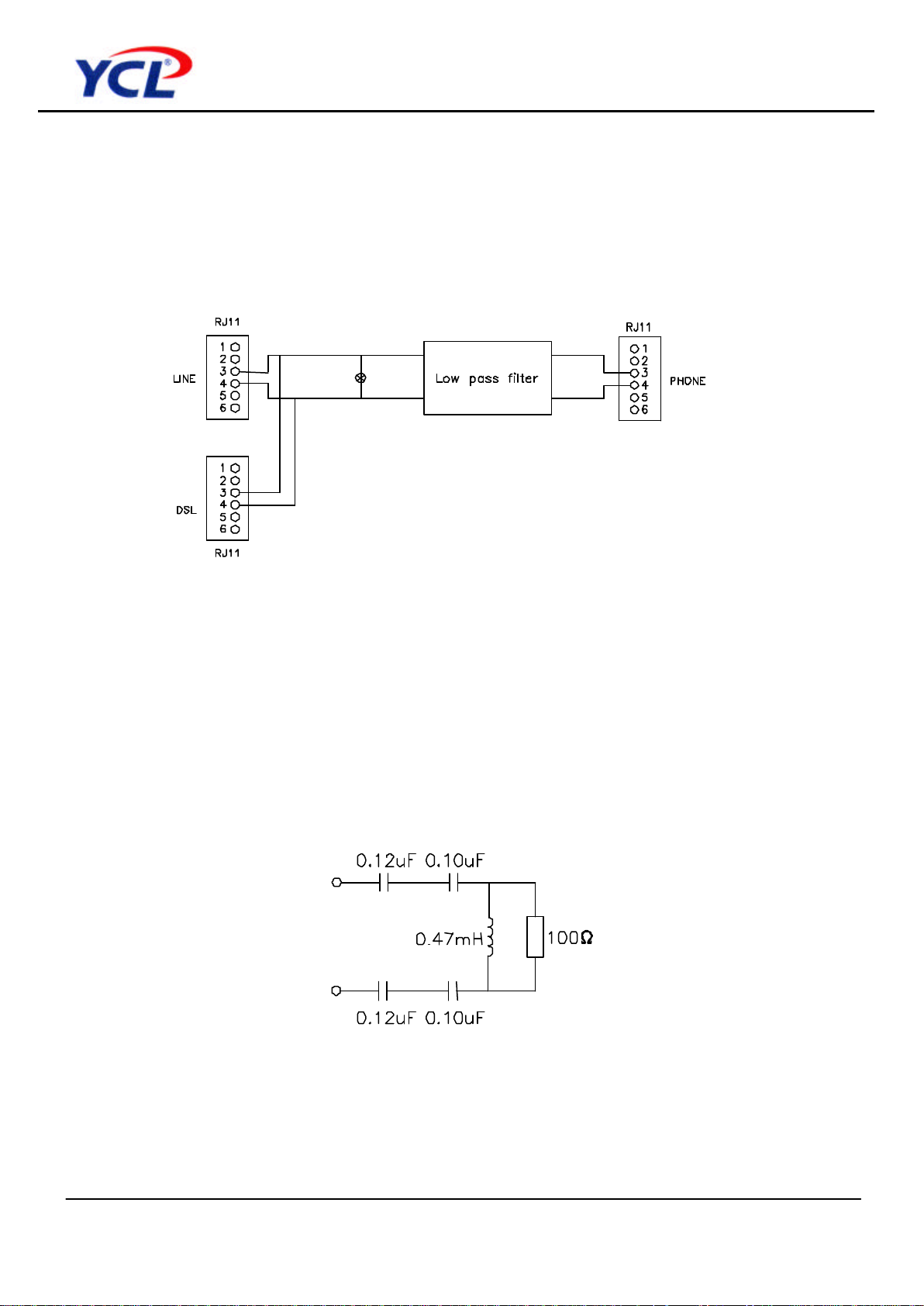
4.1.Schematic :
The following drawing illustrates the schematic of this product.
4.2. ZHP-r definition :
To facilitate the test of the splitter , the high pass data have to be taken into consideration.
Capacitors of 0.1uF on the NT-side are connected in series with 0.12uF capacitors in the
tip-And ring-line of the ADSL-output of the splitter itself (see block diagram above). The
equivalent circuit diagram of the NT-side is shown below :
Page 6

Product Specification
CPF121F
Data sheet subject to change without notice RDPS-POTS438(R1)12/25/2002
SHEET 6 OF 14
4.3. Electrical specification :
Electrical requirements
Item Splitter parameter
Range values
Frequency range
Splitter bandwidth DC to 3.4KHz
Nominal voice band 0.3KHz to 3.4KHz
Ringing frequency 25Hz to 50Hz
ADSL band 30KHz to 1104KHz
Line Impedance ZL 270ohm + (750ohm || 150nF)
CO impedance ZTc 270ohm + (750ohm || 150nF)
RT impedance ZTr 270ohm + (750ohm || 150nF)
Modem impedance 30KHz< f< 1104KHz 100 ohm
Operation voltage voice band
Nominal signal 21mVpp to 5.4 Vpp
Billing tone 10Vpp to 30.2Vpp
Ringing signal 25Hz 100Vrms
DC voltage 45V to 52V
Max. AC voltage 150Vrms with -105VDC offset
Current voice band
Loop current <=80mA
1 Polarity independence All
All other electrical performance
requirements shall be met for both
DC polarities
2
Shunt capacitance between Awire and B-wire terminals
DC or low freq.<=50Hz <=150nF
3
Resistance between each line
terminal and earth at 250 V DC
DC >=10Megohm
4
Resistance between A-wire and
B-wire terminals at 250V DC
DC >=10Megohm
5
Series resistance at POTS port
with line port S/C (Clause 6.2.3
Ref. 5)
DC <=50ohm
1
Page 7

Product Specification
CPF121F
Data sheet subject to change without notice RDPS-POTS438(R1)12/25/2002
SHEET 7 OF 14
Electrical requirements
Item Splitter parameter
Range values
6
Ringing signal impedance at line
port and POTS port
(Clause 6.3 Ref. 5)
25Hz & 50Hz <=2 V RMS
7
Ringing signal impedance at line
port and POTS port
(Clause 6.3 Ref. 5)
25Hz & 50Hz >=40kohm
<1dB with source & load
impedance = Z
R
8
Insertion loss(Off-hook)
(Clause 6.5.1 Ref. 5)
1KHz
<1dB with source & load
impedance = 600 ohm
8(a)
Insertion loss (On-hook)
(Clause 6.4.2.1 Ref. 5)
1KHz
<1dB with source & load
impedance = 600 ohm
8(b)
On-hook high-impedance voltage
gain(Clause 6.4.1 Ref. 5)
200Hz to 2800Hz
Voltage gain shall be within range
of – 4dB to +4 dB with source
impedance =ZR & load impedance
=Z
ON
<1 dB with source & load
impedance = Z
R
9
Insertion loss distortion
(magnitude of difference of
insertion loss at 1 kHz and that at
another frequency) (Off-hook)
(Clause 6.5.2 Ref. 5)
200Hz to 4000Hz
<1 dB with source & load
impedance =600 ohm
9(a)
Insertion loss distortion(On-hook)
(Clause 6.4.2.2 Ref. 5)
200Hz to 2800Hz
<±1dB with source & load
impedance = 600 ohm
300Hz to 3400Hz
>=12 dB with termination &
reference impedance Z
R
10
Return loss at line port and
POTS port (Off-hook)
(Clause 6.6 Ref. 5)
3400Hz to 4000Hz
>=12 dB with termination &
reference impedance Z
SL
50Hz to 600Hz
>=46 dB with R = 300 ohm & S1
closed
600Hz to 3400Hz
>=52 dB with R = 300 ohm & S1
closed
3400Hz to 4000Hz
>=46 dB with R = 300 ohm & S1
closed
4000Hz to 30kHz
>=40 dB with R = 50 ohm & S1
closed
30kHz to 1104kHz
>=50 dB with R = 50 ohm & S1
closed
11
Longitudinal conversion
loss(LCL)
Measured at POTS port
(Test Port = POTS port)
(a) with S2 open &
(b) with S2 closed
Measured at Line port
(Test Port = line port)
with S2 closed
(Test method only- as per Clause
6.8 Ref. 5)
1104kHz to 5MHz
>=30 dB with R = 50 ohm & S1
closed
Page 8

Product Specification
CPF121F
Data sheet subject to change without notice RDPS-POTS438(R1)12/25/2002
SHEET 8 OF 14
Electrical requirements
Item Splitter parameter
Range values
12
Isolation (Off-hook)
(Clause 6.9.2 Ref. 5)
32 kHz to 1104 kHz >=55dB
12(a)
Isolation (On-hook)
{= On-hook loss}
(Clause 6.9.1 Ref. 5)
25 kHz to 1104 Hz Mask of Fig. 1 below
13
Voice band noise at both line port
and POTS port
(Off-hook)(Clause 6.10.1 Ref. 5)
300Hz to 4000 Hz <-75 dBmp
14
ADSL band noise at both
ADSL port and line port
(Off-hook & On-hook)
(Clause 6.10.2 Ref. 5)
26 kHz to 1104 kHz
<-125 dBm/Hz in any 10kHz
bandwidth
2nd harmonic <= -57 dB wrt
fundamental
16
Intermodulation noise
(Off-hook & On-hook)
(Clause 6.11 Ref. 5)
4 Tones
3rd harmonic<=-60 dB wrt
fundamental
<=250 us with source & load
impedance = 600 ohm
200 Hz to 600 Hz
<=250 us with source & load
impedance = Z
R
<=200 us with source & load
impedance = 600 ohm
600 Hz t m o 3200 Hz
<=200 us with source & load
impedance = Z
R
<=50 us with source & load
impedance = 600 ohm
17
Group delay distortion
(Off-hook & On-hook)
(Clause 6.12 Ref. 5)
3.2 kHz to 4.0 kHz
<=50 us with source & load
impedance = Z
R
Peak – to – peak volts <2 V
18
Immunity to high-level POTS
signals
Simulated transients
Resonant frequency <15 kHz
Page 9

Product Specification
CPF121F
Data sheet subject to change without notice RDPS-POTS438(R1)12/25/2002
SHEET 9 OF 14
Note :
Applying an input test signal of – 6 dBv emf to either the POTS or LINE port of the splitter ,
the maximum output voltage level measured over the load impedance shall be below the
template of figure 1.
Figure 1 : On – hook voltage gain template
( maximum allowed output voltage with input of – 6dBV)
4.4. Z
ADSL
defined (Clause 5.2.1) :
This substitute circuit shown in below is a model which shall be applied to a POTS splitter
when verifying requirements of the low pass filter.
The purpose of this model impedance is for splitter specifications ,it is not a requirement on
the input impedance of the ADSL transceiver.
1
Page 10

Product Specification
CPF121F
Data sheet subject to change without notice RDPS-POTS438(R1)12/25/2002
SHEET 10 OF 14
4.5. ZR and ZRL defined ( clause 5.2.2 ) :
For most requirements relating to voice band frequencies described in the present
document, either the terminating impedances ZR or Z
SL
is used to terminate the POTS port
or the Line port. ZR is the European harmonized complex impedance, Z
SL
is an impedance
used in TBR 038 [1] to simulate a short line terminated in 600 Ω .
4.6. Z
RHF
defined ( clause 5.2.3 ) :
For requirements relating to ADSL frequencies described in the present document, the
terminating impedance Z
RHF
is used to terminate POTS and line ports of the low pass filter.
This is the European harmonized complex impedance ZR with the modification proposed in
TR 102 139 [2]. This network is shown in below.
4.7. Zon defined ( clause 5.2.4 ) :
For some on - hook requirements ( as defined in clause 5.1.2 ) described in the present
document, the terminating impedance Z
ON
is used.
Actual impedances will vary greatly especially over the ADSL frequency range and thus the
impedance model adapted here is just intended for the verification of splitters. It is not
intended to be an equivalent circuit for a POTS TE.
Impedance Z
R Impedance Z
SL
Impedance Z
RHF
Impedance model to be used for
some on-hook requirements
1
1
1
Page 11

Product Specification
CPF121F
Data sheet subject to change without notice RDPS-POTS438(R1)12/25/2002
SHEET 11 OF 14
4.8. Test method :
4.8.1. Insertion loss :
The insertion loss of a device connected into a given transmission system is defined as the
ratio, expressed in dB, of the load power available ( before and after insertion ) delivered to
the output network beyond the point of insertion at a given frequency. In general , the
insertion loss of a device inserted in a given transmission system mainly caused by internal
component resistive loss while all of the impedance between source , load and device
interface having been matched. To perform the insertion loss measurement , thru calibration
must be done prior the testing. General Insertion loss equation can be expressed as
following.
Insertion loss = 20 log V2 / V1 dB where
V1 = the measured voltage value of load without LPF in circuit.
V2 = the measured voltage value of load with LPF in circuit.
The test setup is shown in drawing below. :
1
Page 12

Product Specification
CPF121F
Data sheet subject to change without notice RDPS-POTS438(R1)12/25/2002
SHEET 12 OF 14
4.8.2. Return loss :
Return loss measure the amount of energy that is lost due to reflection which resulted
from impedance mismatching at the interface. Return loss is essentially defined as the
ratio of the power incident upon a given transmission system to the power reflected
caused by impedance mismatch with respect to reference impedance at the interface
between source and device. Return loss figure are a function of the impedance of the
circuit involved and are therefore frequency dependent. These impedance must be
closely maintained in order to reduce the possibility of undesirable reflection and
echoes which in long distance circuit the telephone user or destroy the data being sent.
To perform the return loss test ,open ,short, load calibration must be done prior
measurement while the LCZ impedance Analyzer being selected in impedance mode.
Return loss is general expressed in decibels.
General Return loss equation as below:
Return loss = 20 log Z
Load
+ ZM / Z
Load
- ZMdB
Where Z
Load
= the reference impedance ZM = the measured impedance
The test setup is shown in drawing below :
Note:
Z
Load
defined :
ZR=270 ohm+(750ohm//150nf)
ZSL=82 ohm+(600ohm//68nf)
1
Page 13

Product Specification
CPF121F
Data sheet subject to change without notice RDPS-POTS438(R1)12/25/2002
SHEET 13 OF 14
5. Environmental condition:
5.1. Resistibility to overvoltages and overcurrents:
The splitter has to comply with requirements as per ITU-T K.21.
5.2. Climatic conditions:
5.2.1. Operating temperature:
Application indoor
Long time operation guarantee temperature ( 5 to 40 0C )
Short time operation guarantee temperature ( 0 to 50 0C )
( According to ETS 300 019, class 3.2 )
5.2.2. Storage and transport:
Low ambient temperature - 20 0C
High ambient temperature +85 0C
( According to MIL-STD-202 method 107 )
5.2.3. Operation humidity:
Long time operation guarantee humidity ( 5 to 85 % )
Short time operation guarantee humidity ( 5 to 90 % )
Short time : within 72 continuous hours and 15 days in a year
6. Reliability conditions:
6.1. Thermal shock :
Temperature from -20 °C to +85 °C for 5 cycles
(According to MIL-STD- 202 , method 107)
6.2. Temperature humidity exposure :
+50 °C /95RH , 96hrs
(According to MIL-STD- 202 , method 103)
6.3. Vibration test :
Random vibration , frequency 5-500Hz , sweep time :1 hr / axis /
Force : 2.4grams (According to MIL-STD-202 , method 204)
Page 14

Product Specification
CPF121F
Data sheet subject to change without notice RDPS-POTS438(R1)12/25/2002
SHEET 14 OF 14
7 . Mechanical Condition :
7.1. Mechanical :
Note : (1)all tolerance : ± 0.25mm(0.001)inch
(2) color code for case:91H301B0
 Loading...