

Page 1

Product Specification
CPF107J
Data sheet subject to change without notice RDPS-POTS415(R1)09/19/2002
SHEET 1 OF 10
File No RDPS-POTS415
Revision R1
System Application Asymmetric Digital Subscriber Line
Product Type POTS Splitter For ADSL CPE side
Product Name CPF107J
Date Sep. 19th, 2002
Jason Hung - Design Engineer, R&D_1Issued By
Roger Wu – Manager, R&D_1Approved By
Issued Date
YCL Electronics Co., Ltd.
No.95, Feng Jen Road. Feng Shan City, Kaohsiung, Taiwan, R.O.C.
This controlled document is the property of YCL Electronics Co., Ltd. Any duplication
reproduction or transmission by unauthorized parties without the prior written
permission of YCL Electronics Co., Ltd. is prohibited.
Page 2

Product Specification
CPF107J
Data sheet subject to change without notice RDPS-POTS415(R1)09/19/2002
SHEET 2 OF 10
Table of contents
Item Description Page
1 Introduction
-----------------------------------------------
3
2 Reference
-----------------------------------------------
3
3 Abbreviations
-----------------------------------------------
4
4
Technical requirements
-----------------------------------------------
4
4.1. Schematic
-----------------------------------------------
4
4.2. ZHP-r definition
-----------------------------------------------
5
4.3. DC characteristic
-----------------------------------------------
5
4.4. Test loops
-----------------------------------------------
5
4.5. Slectrical Specification
-----------------------------------------------
6
4.6. Test Method
-----------------------------------------------
7
4.6.1. Insertion loss
-----------------------------------------------
7
4.6.2. Return loss
-----------------------------------------------
8
4.6.3. Attenuation Distortion in the Voice Band
-----------------------------------------------
9
5 Environmental condition
-----------------------------------------------
9
5.1. Resistibility to overvoltage and
overcurrents
-----------------------------------------------
9
5.2. Climatic condition
-----------------------------------------------
9
5.2.1. Operating temperature
-----------------------------------------------
9
5.2.2. Storage and transport
-----------------------------------------------
9
5.2.3. Operating humidity
-----------------------------------------------
9
6 Reliabilty conditions
-----------------------------------------------
9
6.1.Thermal shock
-----------------------------------------------
9
6.2. Temperature humidity exposure
-----------------------------------------------
9
6.3. Vibration test
-----------------------------------------------
9
7 Mechanical design
-----------------------------------------------
10
7.1. Mechanical
-----------------------------------------------
10
7.2. Connector information
-----------------------------------------------
10
Page 3

Product Specification
CPF107J
Data sheet subject to change without notice RDPS-POTS415(R1)09/19/2002
SHEET 3 OF 10
1. Introduction:
The CPF107J is a splitter module that has been specifically designed to implement the
functionality of low pass filter in POTS over ADSL application at CPE side.
Asymmetric Digital Subscriber Line (ADSL) technology is dedicated , point to point , public
network access technology that allow multiple forms of data , voice , and video to be carried
over twisted-pair copper wire on the local loop between a network service provider’s(NSP’S)
central office and the customer site or on local loops created either intra-building or intracampus. Best of all , ADSL delivers this high speed performance over existing copper
telephone line all while allowing traditional voice service to coexist without interruption
through POTS low pass filters. The POTS-splitter on the customer premises side consists of
a low pass section(installed in a separated plastic box).
The CPF107J integrate low pass filter that block the high frequency energy from reaching the
POTS device and provide isolation from impedance effects of the POTS device on ADSL. In
addition , these filter will also attenuate any wideband impulse noise generated by the POTS
device due to the interruption of loop current(e.g. pulse dialing or on hook / off hook transfer).
Because the POTS splitter connects directly to the subscriber loop media , it must also
provide some protection for externally induced line hits or faults which could damage any
attached equipment or endanger humans interacting with the installed equipment.The circuit
protection will be provided mostly by standard central office line protection means and
additional protection measures built into pots splitter to protect against line overstress which
could damage the splitter itself.
2. Reference:
Ref. 1 : ETS 300 001 Attachment to Public Switched Telephone Network
Ref. 2 : ITU G992.1 Specification and testing methods for a ANNEX Type 4 POTS
splitter appropriate to Japan
Ref. 3 : ITU K.21 Resistibility of subscribers terminal to overvoltage and
overcurrents
Page 4

Product Specification
CPF107J
Data sheet subject to change without notice RDPS-POTS415(R1)09/19/2002
SHEET 4 OF 10
3. Abbreviations:
ADSL Asymmetric Digital Subscriber Line
CO Central Office
CPE Customer Premise Equipment
POTS Plain Old Telephone Service
RT Remote Terminal
ADSL-NT Network termination of ADSL
ERL Echo Return Loss
SRL Singing Return loss for low frequency
SRL-H Singing Return loss for high frequency
4. Technical requirements:
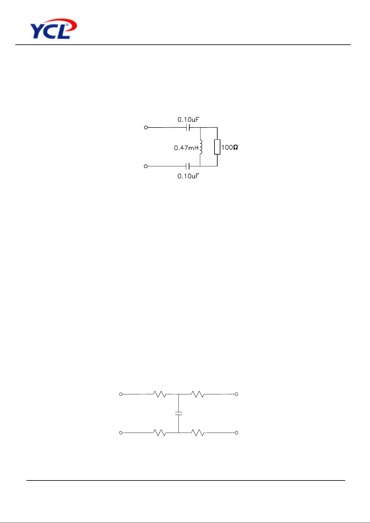
4.1. Schematic :
The following drawing illustrate the block diagram of this product.
Page 5
Product Specification
CPF107J
Data sheet subject to change without notice RDPS-POTS415(R1)09/19/2002
SHEET 5 OF 10
4.2. ZHP-r Definition :
ZHP-r is defined to be the impedance presented to the POTS connection by an ATU-R. The
equivalent circuit of ZHP-r is showing below. The ZHP-r is valid only for voice band
frequencies. The combination of capacitors in the ZHP-r is only representative.
4.3. DC characteristic :
All requirement of this specification can be met in the presence of all POTS loop currents
from 0mA to 130mA. This in line filter can pass POTS tip-to-ring dc voltages of 0V to 60V
and ringing signals of maximum 100Vrms at any frequency from15Hz to 30Hz with a dc
component in the range from 0V to 60V. The dc resistance from tip-to-ring at the line port
interface with the phone interface shorted, shall be less than or equal to 40 ohms for one
splitter.
The DC resistance from tip-to-ground and from ring-to-ground at the POTS interface with
the U-R interface open shall be greater than or equal to 10 Megohms. The ground point
shall be local building or green wire ground. As an objective , the dc resistance should
exceed 10MΩ.
4.4. Test loops :
This test loop model is valid only for voiceband frequencies.
140ohms
140ohms
140ohms
140ohms
100nF
Page 6

Product Specification
CPF107J
Data sheet subject to change without notice RDPS-POTS415(R1)09/19/2002
SHEET 6 OF 10
4.5. Electrical Specification :
The low pass filter shall satisfy the following parametric limits shown in this table across the
Line side of this device.
Electrical requirements
Splitter parameter
Range values
Splitter bandwidth DC to 3.4KHz
Nominal voice band 0.2KHz to 4KHz
Ringing frequency 15Hz to 30Hz
ADSL band 30KHz to 1104KHz
Line Impedance ZL 300 Hz < f < 3.4 KHz 600 ohm
Modem impedance 30 KHz < f < 1104 KHz 100 ohm
Operation voltage voice band
Nominal signal 21mVpp to 5.4 Vpp
Ringing signal 100Vrms
DC voltage 0V to 120V
Max. AC voltage 100Vrms
Max. differential 320V
Line Impedance ZL 600 ohm
CO impedance ZTc
150Ω + (72nF || 830Ω)
RT impedance ZTr
150Ω + (72nF || (830Ω+1uF)
Current voice band
Loop current <=130mA
DC Resistance
DC Resistance <=40 ohm
Isolation resistance tip/ring >10 Mohm
Voice –band characteristic
Insertion loss 1000Hz <1.0 dB
Attenuation distortion
(relative to 1000Hz)
200Hz<f<3.4KHz <1.0dB
Attenuation distortion
(relative to 1000Hz)
3.4KHz<f<4KHz <1.5dB
Delay distortion 600Hz<f<3.2KHz <200 usec
200Hz<f<4KHz <250 usec
Return loss 200Hz<f<1.5KHz >11dB
1.6KHz<f<2KHz >10dB
2.1KHz<f<3.4KHz >9dB
Longitudinal conversion loss LCL 200Hz to 3.4KHz >58dB
ADSL modem interface
Isolation voltage >2000Vrms for 1 minute
Rejection attenuation at
boundary band
4KHz<f<25KHz >26.48 log2 ( f / 4 )dB
25KHz<f<300KHz >70dB
Rejection attenuation at ADSL
band
300KHz<f<1104KHz >55dB
Loading of ADSL signal path 25KHz<f<1104KHz >0.35dB
Page 7

Product Specification
CPF107J
Data sheet subject to change without notice RDPS-POTS415(R1)09/19/2002
SHEET 7 OF 10
4.6. Test method :
4.6.1. Insertion loss :
For each of the test loops specified in above and using the test set-up shown in Figure 1
the insertion loss from the source to the termination shall be measured with and without
the splitter/ ZHP-r combination inserted.The increase in insertion loss at 1000 Hz on any
of the test loops, due to the addition of the Splitter/ZHP-r shall be less than specified in
Electrical Specification table.
The insertion loss of a device connected into a given transmission system is defined as
the ratio, expressed in dB, of the load power available(before and after insertion )
delivered to the output network beyond the point of insertion at a given frequency. In
general , the insertion loss of a device inserted in a given transmission system mainly
caused by internal component resistive loss while all of the impedance between source ,
load and device interface having been matched. To perform the insertion loss
measurement ,thru calibration must be done prior the testing . General Insertion loss
equation can be expressed as following
Insertion loss = 20 log V2 / V1 dB where
V1 = the measured voltage value of load without LPF in circuit.
V2 = the measured voltage value of load with LPF in circuit.
The test setup is shown in drawing below. :
Note : ZHP-r is the impedance presented to the POTS connection by an ATU-R
Figure 1
Remote POTS Splitter
ZT
TEST
xDSL
ZHP-r
TEST
ZTr
ZTr is the normal
Termination in test set
(Load)
(600ohm)
(600ohm
equipment
loop
Page 8

Product Specification
CPF107J
Data sheet subject to change without notice RDPS-POTS415(R1)09/19/2002
SHEET 8 OF 10
4.6.2. Return loss for POTS splitter:
The Return Loss is measure of the driving point impedance variation introduced by the
filter, variation of the driving point impedance of the loop can affect POTS performance by
changing the sidetone balance of a telephone instrument or the front-end hybrid balance
of voiceband modem. Return loss measure the amount of energy that is lost due to
reflection which resulted from impedance mismatching at the interface. Return loss is
essentially defined as the ratio of the power incident upon a given transmission system to
the power reflected caused by impedance mismatch with respect to reference impedance
at the interface between source and device.
Return loss figure are a function of the impedance of the circuit involved and are therefore
frequency dependent.These impedance must be closely maintained in order to reduce the
possibility of undesirable reflection and echoes which in long distance circuit the
telephone user or destroy the data being sent.To perform the return loss test ,open ,short,
load calibration must be done prior measurement while the LCZ impedance Analyzer
being selected in impedance mode. Return loss is general expressed in decibels. General
Return loss equation as below :
Return loss = 20 log ZNL-r* - ZM / ZNL-r + ZMdB
Where ZNL-r = the reference impedance ZM = the measured impedance
The test setup is shown in drawing below:
1: ZNL – r= 150 ohm + ( 72nF //(830ohms + 1uF))
2: ZHP-r is the impedance presented to the POTS connection by an ATU-R.
Figure 2
Test Equipment
Remote POTS Splitter
ZNL-r
LPF
ZNL-r
ZHP-r
xDSL
Page 9

Product Specification
CPF107J
Data sheet subject to change without notice RDPS-POTS415(R1)09/19/2002
SHEET 9 OF 10
4.6.3. Attenuation Distortion in the Voice band :
The variation of insertion loss with frequency shall be measured using the test set up in
Fig.1 The defined ZHP-r will be attached to the xDSL port of the Splitter.(if the Splitter is
an internal part of the ATU, then the modem remains attached as the xDSL load).The
increase in Attenuation Distortion, relative to the 1000 Hz insertion loss caused by the
POTS Splitter. Including the ZHP-r ( or modem ) load attached, using each of the test
loops identified above shall be within Electrical Specification table.
5. Environmental condition:
5.1. Resistibility to overvoltages and overcurrents:
The splitter has to comply with requirements as per ITU-T K.21.
5.2. Climatic conditions:
5.2.1. Operating temperature:
Application indoor
Long time operation guarantee temperature ( 5 to 40 0C )
Short time operation guarantee temperature ( 0 to 50 0C )
( According to ETS 300 019, class 3.2 )
5.2.2. Storage and transport:
Low ambient temperature - 20 0C
High ambient temperature +85 0C
( According to MIL-STD-202 method 107 )
5.2.3. Operation humidity:
Long time operation guarantee humidity ( 5 to 85 % )
Short time operation guarantee humidity ( 5 to 90 % )
Short time : within 72 continuous hours and 15 days in a year
6. Reliability conditions:
6.1. Thermal shock :
Temperature from -20 °C to +85 °C for 5 cycles
(According to MIL-STD-202 , method 107)
6.2. Temperature humidity exposure :
+50 °C /95RH , 96hrs
(According to MIL-STD-202 , method 103)
6.3. Vibration test :
Random vibration , frequency 5-500Hz , sweep time :1 hr / axis /
Force : 2.4grams (According to MIL-STD-202 , method 204)
Page 10

Product Specification
CPF107J
Data sheet subject to change without notice RDPS-POTS415(R1)09/19/2002
SHEET 10 OF 10
7 . Mechanical Condition :
7.1. Mechanical :
Note : Unit mm
7.2. Connector information :
Function Style Tip Ring
Line RJ 11 Pin 3 Pin 4
DSL RJ 11 Pin 3 Pin 4
Phone RJ 11 Pin 3 Pin 4
1
 Loading...