

Page 1
Corporate: www.cdtechno.com
Product: www.cdpowerelectronics.com
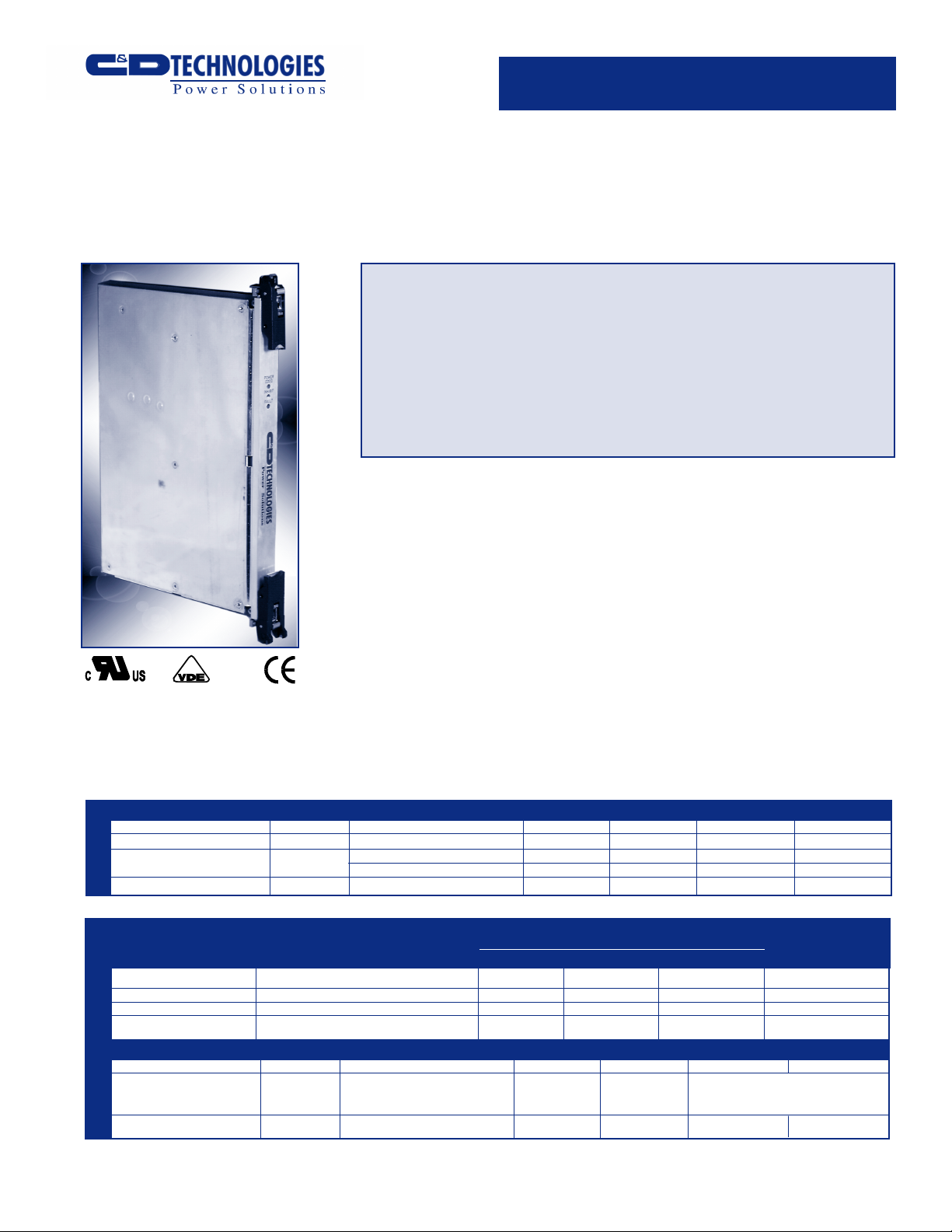
cPCI500DC
500 Watt, 6U x 4HP, CompactPCI
Corporate: www.cdtechno.com
6U X 4HP
36-72 VDC Input Range
500 Watt Continuous Output
Power
Complies with PICMG 2.11
R1.0 with 47 Pin I/O Connector
Hot-Swap Capable
The cPCI500DC is a high-reliability,
500 watt power supply for 6U Compact
PCI™ systems. Developed to support
hot-swap, redundant operation, the
cPCI500DC is designed for compliance
with PICMG™ 2.11 R1.0 Power
Interface Specification with 47-pin I/O
connector, as well as the underlying
CompactPCI™ standards. Available
with IPMI functionality, this unit was
developed with high-availability (HA)
Outputs Individually Protected
Against Overloads; Automatic
Recovery
PCI VoltageArchitecture
(5V, 3.3V,+12V,-12V)
IPMI Capability
No Minimum Load
telecommunications applications in
mind. Current sharing and internal
ORing diodes are included to support
these and other applications requiring
reliable, hot-swap performance and N+1
redundant configuration. The 4HP
package and complement of agency
approvals provide for an advanced,
high-density, high-efficiency power
solution for your CompactPCI™ system
requirements.
SPECIFICATIONS, ALL MODELS
PARAMETER SYMBOL CONDITIONS MIN TYP MAX UNITS
Input Operating Voltage Vin 36 72 VDC
Input Voltage Withstand 34 75 VDC
Inrush Current I
INPUT
Efficiency η 48VDC input, 500W load 80 %
OUTPUT NUMBER RATED OUTPUT VOLTAGE Min A* B* REGULATION
V1 +5.0VDC 0A 55.0 A 30.0 A +/-1%
V2 +3.3VDC 0A 30.0 A 60.0 A +/-1%
V3 +12.0VDC 0A 11.0 A 11.0 A +/-1%
V4 -12.0VDC 0A 1.75 A 1.75 A +3, -3%
PARAMETER SYMBOL CONDITIONS MIN TYP MAX UNITS
OUTPUT
Temperature Coefficient TC 0.02 %/°C
PARD 20MHz bandwidth 50 mV
Output Power 50°C max temp. 500 W
* Total output power not to exceed 500 Watts
i
VOUT RATED OUTPUT CURRENTOUTPUT
36VDC input 10 APK
72VDC input 20 APK
IOUT
all outputs or 1.5% P-P
whichever is greater
cPCI500-DC REV D 8/2002
P-P
Page 2

SPECIFICATIONS, ALL MODELS
Transient Response
For a step load change of 50%-100%-50%, the peak output
excursion will not exceed 8% of nominal voltage, and will
recover to within 1% of nominal voltage within 200
microseconds.
Current Share
Active current sharing is employed on Outputs V1, V2 and V3.
Remote Sense
Outputs V1, V2, and V3 are capable of compensating up to
DC of line drop. Unit automatically reverts to local
0.3V
sensing in the event that the sense leads are opened for any
reason. Unit is protected against reversed or shorted sense
leads.
Output Power
500W continuous maximum, with 400lfm airflow at a
maximum ambient of 50°C.
Overload Protection
Outputs are individually protected against overloads and
indefinite short circuit with automatic recovery upon removal
of the fault condition.
Over Voltage Protection
All outputs have over voltage protection at 125% typical
(135% max.) of nominal.
Over Temperature Protection
Outputs are individually protected against over temperature.
Outputs will automatically restore upon recovery to
acceptable temperatures.
Output Fault Isolation
Output isolation diodes are present in all outputs to isolate
faults within a failed power supply.
IPMI Option
2
C board is available as a factory-installed option to
An I
provide an IPMI interface to the SM bus. Status functions
include output voltage and current levels as well as the DEG
warning. Output inhibit control can be toggled under software
command. See Application Note ACAN-02 for satellite
controller specification, ACAN-03 for firmware update
procedure and ACAN-04 for test procedure.
Remote Inhibit (INH#)
Secondary referenced, active low, TTL compatible signal
inhibits all outputs upon activation.
Power Fail Warning (FAL#)
Open collector signal indicates output failure. Active low.
Enable (EN#)
Short pin on connector will enable power supply output when
the mating pin is grounded. Supply will not power up until
this pin is engaged to its mate in the backplane. Unit output
will be inhibited as pin is disengaged from the mating
connector.
Temperature Warning (DEG#)
Open collector indicates internal temperatures are approaching
the thermal shutdown limit. Active low.
Fault Indicator LED
A red LED will be ON if output voltages are not within
specification.
Power Present LED
A green LED will be ON when input voltage is present and
above the minimum requirement.
Cooling
400lfm of airflow required to maintain full output power at 050°C ambient. Additional data on operation below 400lfm is
available in Application Note ACAN-01.
Temperature
Full output power achievable over the range of 0-50°C.
Storage temperature limits are –20 to +85°C. Additional data
on operation above 50°C is available in Application Note
ACAN-01.
Altitude
Operating: -200 to +10,000 feet with ambient temperature
derating above 5,000 feet in accordance with the adiabatic
lapse rate.
Inhibit Indicator LED (Yellow)
A yellow LED will be ON when the outputs are inhibited.
Product: www.cdpowerelectronics.com
cPCI500-DC REV D 8/2002
2
Page 3

MECHANICAL
NOTES: All measurements are in inches.
CONNECTOR:IEC Number is pending.
PIN ASSIGNMENT: Pin assignment consistent with PICMG™ 2.11R1.0 specification. The table below details the PICMG™ assignment.
Pin # 1Staging
1-4 M V1 V1 Output
5-12 M RTN V1 and V2 Return
13-18 M V2 V2 Output
19 M RTN V3 Return
20 M V3 V3 Output
21 M V4 V4 Output
22 M RTN Signal Return
23 M RESERVED Reserved
24 M RTN V4 Return
25 M GA0 Geographic Address Bit 0
26 M RESERVED Reserved
27 S EN# Enable
28 M GA1 Geographic Address Bit 1
29 M V1ADJ V1 Adjust
30 M V1 SENSE V1 Remote Sense
31 M GA2 Geographic Address Bit 2
32 M V2ADJ V2 Adjust
33 M V2 SENSE V2 Remote Sense
34 M S RTN Sense Return
35 M V1 SHARE V1 Current Share
36 M V3 SENSE V3 Remote Sense
37 M IPMB SCL IPMB Serial Clock Line
38 M DEG# Degrade Signal
39 M INH# Inhibit
40 M IPMB SDA IPMB Serial Data Line
41 M V2 SHARE V2 Current Share
42 M FAL# Fail Signal
43 M IPMB PWR IPMB Power Input
44 M V3 SHARE V3 Current Share
45 L CGND Chassis Grnd (Safety Grnd)
46 M ACN/+DC IN AC Input Neutral/+DC Input
47 M ACL/-DC IN AC Input Line/-DC Input
NOTES: (1) Pin numbers correspond to the female backplane connector.
(2) L = Long Length Pin (First Make, Last Break); M = Medium
Length Pins; S = Short Length Pins (Last Make, First Break)
2
Signal Name Description
MECHANICAL
Shock: MIL-STD-810d, Method 516.3, Procedure 1.
Vibration: MIL-STD-810d, Method 514.3, Procedure 1.
Dimensions: 6U x 4HP x 160mm (see Mechanical above)
EMC & SAFETY
EMI: NEBS Compliant
ETSI Compliant
Safety Agency Ratings
Input Voltage: 48 VDC
Input Current: 15A
Input Power: 620W
Agency Approvals
UL1950/CSA950, EN60950, CE Mark.
(Low Voltage Directive)
Product: www.cdpowerelectronics.com
cPCI500-DC REV D 8/2002
3
Page 4

Power Electronics Division, United States
3400 E Britannia Drive, Tucson, Arizona 85706
Tel: 800.547.2537 Fax: 520.295.4197
Any data, prices, descriptions or specifications presented herein are subject to revision by C&D Technologies, Inc. without notice. While such information is believed to
be accurate as indicated herein, C&D Technologies, Inc. makes no warranty and hereby disclaims all warranties, express or implied, with regard to the accuracy or
completeness of such information. Further, because the product(s) featured herein may be used under conditions beyond its control, C&D Technologies, Inc. hereby
disclaims all warranties, either express or implied, concerning the fitness or suitability of such product(s) for any particular use or in any specific application or arising from
any course of dealing or usage of trade. The user is solely responsible for determining the suitability of the product(s) featured herein for user’s intended purpose and
in user’s specific application. C&D Technologies, Inc. does not warrant or recommend that any of its products be used in any life support or aviation or aerospace
applications.
Tel: +44 (0)1908 615232 Fax: +44 (0)1908 617545
C&D Technologies, (NCL)
Milton Keynes MK14 5BU UK
Product: www.cdpowerelectronics.com
cPCI500-DC REV D 8/2002
4
 Loading...