

Datasheet ATAB5423-3-WB, ATAB542x-x-WB, ATAB5428-4-WB, ATAB5428-8-WB, ATAB5429-9-WB Datasheet (Atmel)
...Page 1

ATAB542x-x-WB User Guide
..............................................................................................
ATMEL “Wireless BlackBird”
Transceiver Demonstration Kit
Page 2

Introduction........................................................................................... 1-1
1.1 Purpose.....................................................................................................1-1
1.2 Description ................................................................................................1-1
1.3 Performance Characteristics .....................................................................1-2
1.4 Kit Contents...............................................................................................1-2
Operating the Transceivers .................................................................. 2-1
2.1 Menu Guide Description............................................................................2-1
2.2 The Abridged Menu Guide ........................................................................2-2
2.3 The Exhaustive Menu Guide .....................................................................2-3
Appendix............................................................................................... 3-1
3.1 Miscellaneous Information ........................................................................3-1
3.1.1 Software re-load and FUSE settings ..................................................3-1
3.1.2 Software documentation .....................................................................3-2
ATAB542x-x-WB User Guide -1
5219A–WIRE–04/07
Page 3

Section 1
Introduction
Congratulations on your purchase of the ATMEL ATAB542x “Wireless BlackBird“ Transceiver Demonstration Kit. This kit is built around the ATA542x RF transceiver IC and the
ATmega3290 AVR
This User Guide describes the Demonstration Kit features and provides two versions of
the menu system in the demo software – (1) an abridged version which gives the top
two tiers of the menu, and (2) an exhaustive version which gives the menu in full detail,
including the resulting action from all possible joystick movements at each point in the
menu.
For the most rapid path to executing a working demo with the transceiver pair, see the
Quick Start Card included in the package. It shows how to execute the Link Quality
demo – a demo in which each transceiver in the pair measures and displays the relative
signal strength of the other transceiver’s RF transmission.
1.1 Purpose The Wireless BlackBird kit, consisiting of a pair of transceivers, was designed with a
positive out-of-the-box experience in mind. Using the Quick Start Card included in the
package, an end-user can, within a matter of minutes, have a demonstration running.
This User's Guide outlines the demo-software menu, providing a complete, single document which the end-user can reference while becoming intimately familiar with the many
features of the demo.
®
micro-controller.
Equally so, this kit is suitable for a developer who wishes to explore the full capabilities
of the ATA542x radio and the AVR micro-controller. Through the ISP, UART, or JTAG
interface, the developer has complete control.
1.2 Description The ATMEL Wireless BlackBird is a 2" x 3.5" PC-board transceiver using the ATA542x
UHF transceiver IC and the ATmega3290 AVR micro-controller, as shown in Figure 1-1.
It is offered in five frequencies: 315, 345, 434, 868, and 915 MHz. The BlackBird is
UART-, ISP-, and JTAG- ready. It has a custom LCD display, a 4-way joystick, and is
powered by 2 AAA batteries.
The UART, ISP, and JTAG I/Os allow end-users to load software into the AVR and to
interface with the ATA542x radio. With the joystick, the end-user can navigate through
menus and select functions to execute. The LCD displays the menus, as well as showing transceiver activity during each of the various demo functions.
ATAB542x-x-WB User Guide 1-1
5219A–WIRE–04/07
Page 4

Introduction
The BlackBird is capable of up to 20Kbit/s Manchester FSK modulation, or 10Kbit/s
ASK. Its fractional-N frequency synthesizer gives a nice 800Hz RF resolution. An internal TX/RX switch controls the single-ended RF I/O which is capable of up to 10dBm
(adjustable) output.
The ATMEL part numbers for the different frequency versions are:
ATAB5423-3-WB for 315 MHz
ATAB5425-3-WB for 345 MHz
ATAB5428-4-WB for 434 MHz
ATAB5428-8-WB for 868 MHz
ATAB5429-9-WB for 915 MHz
1.3 Performance Characteristics
Some typical characteristics for the ATA542x BlackBird transceiver board are:
Sensitivity: approximately -102 dBm FSK and -105 dBm ASK
Data Rate: up to 20 Kbit/s FSK and 10 Kbit/s ASK
Frequency/Channels: Multi-channel operation over +/- 2.5 MHz with 800 Hz resolution
Temperature Range: -40C to 85C
Power Output: ~ 0 to ~ 10 dBm (switchable)
Supply Current:
OFF mode: <1 uA
RX mode: 12 mA
TX mode @ ~0 dBm: 12 mA
TX mode @ ~ 8 dBm: 21 mA
Voltage Requirement : 3 or 6 VDC
Range : ≥ 1000 feet
The specifications for the ATA542x transceiver IC are included in its Data Sheet on the
accompanying CD.
1.4 Kit Contents The ATAB542x kit contains two ATAB542x transceivers (with batteries), as determined
by the ATMEL part number ordered, a Quick Start Card, and a CD. The kit is complete,
the software is preloaded, and it is ready for immediate use. Figure 1-2 shows the kit
contents.
Included on the accompanying CD are:
1. User Guide
2. Bills of Material
3. Data Sheets
4. schematic and layout files
5. IAR
6. a *.hex file for the Demo software
7. a Quick Start Guide
1-2 ATAB542x-x-WB User Guide
5219A–WIRE–04/07
®
and WinAVR source code
Page 5
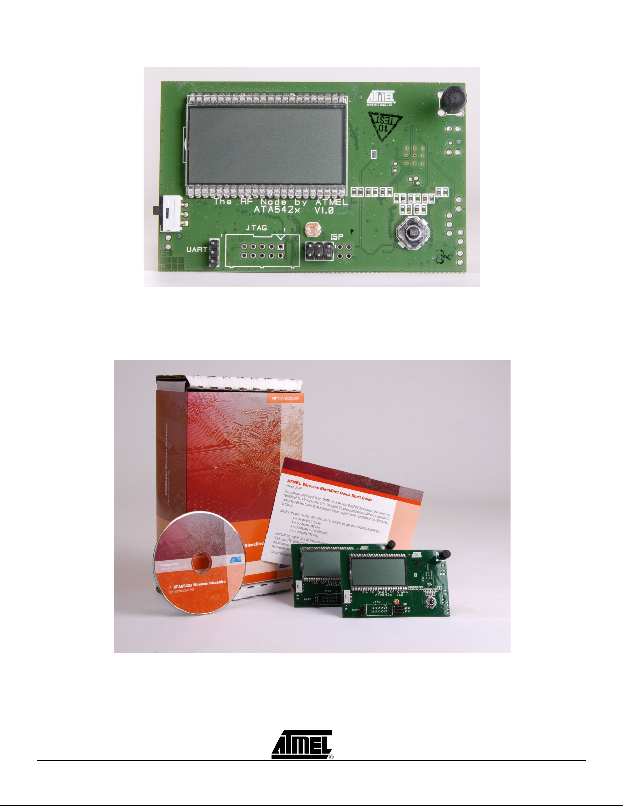
Figure 1-1. Wireless BlackBird Transceiver
Introduction
Figure 1-2. Wireless BlackBird Demonstration Kit
ATAB542x-x-WB User Guide 1-3
5219A–WIRE–04/07
Page 6

Section 2
Operating the Transceivers
This section contains remarks about how the Menu Guides, both abridged and exhaustive, are set-up and how to use them. Then, both versions of the Menu Guide,
respectively, are given.
2.1 Menu Guide Description
These menu guides are intended to provide the user with two views of the demo-software menu. First, the abridged version shows a top-level view of only the first two tiers
of the menu system. At a glance, the user can see what features are demonstrated in
the pre-loaded software. Second, in the exhaustive version, the user has a simple-tonavigate outline with complete details about each feature in the software. Additionally,
in the exhaustive version, short instructions are given for the demonstrations whose
execution is not intuitively clear from simply the outline material alone.
The following are comments important to understanding these guides and navigating
the Demo software menu:
1. anything that appears on the LCD display is highlighted in the outline with bold
text. This helps the user to more quickly spot the place in this outline that corresponds to the current position in the menu system while using the Wireless
BlackBird.
2. there are 5 possible movement of the joystick:
P - press
L - move left
R - move right
U - move up
D - move down
that result in some action. Each is described in the exhaustive version.
3. where reasonable, a few sentences of explanation either complement or replace
the abbreviated descriptions of the joystick movements.
4. unless otherwise stated, these actions apply to each menu item:
L - backs out of the menu item
P - starts/ends/selects the menu item
So, a very important action that the user MUST remember is:
only by pressing (P) the joystick will a selected menu item be stored in
memory!
ATAB542x-x-WB User Guide 2-1
5219A–WIRE–04/07
Page 7

Operating the Transceivers
5. the letters "X" or "x" are used in this outline to indicate display of a number that
has a variable value.
2.2 The Abridged Menu Guide
There are 6 main menus:
DIAGNOSTICS
LINK QUALITY
TEMPERATURE SENSOR
LIGHT SENSOR
FREQ HOPPER
SYSTEM SETUP
They are accessible by moving the joystick downward (not to be confused with pressing
it) or upward after power-up. At each main menu which has sub-menus, these submenus can be accessed by pressing the joystick. Moving the joystick leftward backs out
of the currently-selected sub-menu.
These 6 main menus and each one’s sub-menu are described here:
DIAGNOSTICS - provides transmit and receive functions for testing and evaluation.
The sub-menus are:
MARK - transmits a continuous logic "1" (the upper FSK frequency)
SPACE - transmits a continuous logic "0" (the lower FSK frequency)
TOGGLE - generates a continuous square wave by toggling between MARK and
SPACE (FSK mode)
RSSI - indicates received signal strength
PKT TX - transmits packet data
PKT RX - receives packet data
S LINK - serial link mode; permits two PCs to communicate over an RF link
LINK QUALITY - two transceivers exchange data packets with one-another. Each trans-
ceiver displays the relative strength of the signal it receives.
TEMPERATURE SENSOR - two transceivers exchange with one-another the temperature measurement made by each’s on-board sensor. The temperature measured by a
transceiver’s own sensor, as well as that reported by the other transceiver, is displayed.
LIGHT SENSOR - two or more transceivers exchange with one-another the light intensity measurement made by each’s on-board sensor. This is a multi-transceiver
demonstration with a single MASTER and one or more REMOTEs. The intensity measured by a transceiver’s own sensor, as well as that reported by the other transceiver, is
displayed. NOTE: the REMOTEs communicate only with the MASTER – not with other
REMOTEs.
FREQ HOPPER - two transceivers exchange data packets, in either single or continuous mode, as they hop among pre-set channels.
2-2 ATAB542x-x-WB User Guide
5219A–WIRE–04/07
Page 8

Operating the Transceivers
SYSTEM SETUP - various functions
PWR DWN - puts the transceiver in one of two different sleep modes
CHANNEL ADJUST - adjusts/trims the frequency of the selected channel
UNIT ID ADR - assigns a unit ID to the transceiver
SET DATE/TIME - sets the date and time of the internal clock
PWR LVL - sets the power output (LO ~ 0dBm, HI ~ 8dBm)
LCD SEG ON - displays all segments on the LCD
A/D TST - shows that the A/D converter works
CLK OUT - outputs a square wave at the RC oscillator frequency
TIME - displays day/date/time information
RF MODULE SELECT - loads pre-set register data for each RF frequency
2.3 The Exhaustive Menu Guide
To power-up the transceiver, slide the white-and-black switch downward. The text
ATMEL WIRELESS BLACKBIRD scrolls across the screen. The AVR logo and the
device part number (542x) are also displayed. At this point:
P - displays VERSION X.XX, the current version of the demo software
P,L,R,U,D - goes to power-up display (ATMEL SMARTRF...)
U,D - scrolls through the main menu (DIAGNOSTICS, LINK QUALITY, ...)
P - selects desired menu item
2.3.1 DIAGNOSTICS Contains seven transmit/receive functions
sub-menus: MARK, SPACE, TOGGLE, RSSI, PKT TX, PKT RX, S LINK
P - accesses sub-menus
L - goes to power-up display (ATMEL SMARTRF...)
U,D - scrolls through main menu (DIAGNOSTICS, LINK QUALITY, ...)
2.3.1.1 MARK Transmits a continuous logic "1" (the upper FSK frequency)
P - accesses menu items
L - goes to DIAGNOSTICS
U,D - scrolls thru menu (MARK, SPACE, ...)
CH x - sets radio channel (0 to 9)
P - sets channel and goes to PWR LVL
L - goes to PWR LVL
U - increments channel
D - decrements channel
PWR LVL - sets TX power level
P - sets selected power level (LO/HI) and goes to MARK
L - goes to MARK
U - selects HI power
D - selects LO power
MARK (blinking), channel number, AVR logo, antenna icon, and P LO (or, P HI)
ATAB542x-x-WB User Guide 2-3
5219A–WIRE–04/07
Page 9

Operating the Transceivers
radio is transmitting, indicated by AVR logo and antenna icon
P,L,R,U,D - goes to START and stops transmitting
START - exits or re-starts TX mode
P - re-starts TX mode
L - goes to MARK (main menu)
U,D - goes to EXIT
EXIT - exits TX mode
P,L - goes to MARK (main menu)
U,D - goes to START
2.3.1.2 SPACE Same as the MARK menu, except it transmits a continuous logic "0"
(the lower FSK frequency)
2.3.1.3 TOGGLE Generates a continuous square wave by toggling between MARK and SPACE
(FSK mode)
P - accesses menu items
L - goes to DIAGNOSTICS
U,D - scrolls thru menu (MARK, SPACE, ...)
CH x - sets radio channel (0 to 9)
P - sets channel and goes to FSK
L - goes to FSK
U - increments channel
D - decrements channel
FSK - sets transmitter to ASK or FSK
P - sets mode and goes to x KBPS
U,D - toggles between ASK and FSK
x KBPS - sets data rate, dependent on modulation chosen
P - goes to TOGGLE
U,D - changes data rate (1,5,10 kbps for ASK; 1,5,10,20,40 kbps for FSK)
TOGGLE, AVR logo, antenna icon, and CH x - radio is transmitting, indicated by
AVR logo and antenna icon
P,L,R,U,D - goes to START and stops transmitting
START - exits or re-starts TX mode
P - re-starts TX mode
L - goes to TOGGLE (main menu)
U,D - goes to EXIT
EXIT - exits TX mode
P,L - goes to TOGGLE (main menu)
U,D - goes to START
2-4 ATAB542x-x-WB User Guide
5219A–WIRE–04/07
Page 10

2.3.1.4 RSSI Indicates received signal strength
Note: a 2nd transceiver must be put into one of the above transmit modes (MARK, SPACE, or
TOGGLE) in order to see a received signal strength indication
P - accesses menu items
L - goes to DIAGNOSTICS
U,D - scrolls thru menu (MARK, SPACE, ...)
CH x - sets radio channel (0 to 9)
P - sets channel and goes to FSK
L - goes to FSK
U - increments channel
D - decrements channel
FSK - sets transmitter to ASK or FSK
P - sets mode and goes to x KBPS
L - goes to x KBPS
U,D - toggles between ASK and FSK
x KBPS - sets data rate, dependent on modulation chosen
P - sets data rate and goes to RSSI
L - goes to RSSI
U,D - changes data rate (1,5,10 kbps for ASK; 1,5,10,20,40 kbps for FSK)
RSSI, number, vertical bar-graph - shows a number and bar-graph to indicate
relative signal strength
P,L,R,U,D - goes to RSSI (main menu)
Operating the Transceivers
2.3.1.5 PKT TX Transmits packet data
Note: a 2nd transceiver must be put into the PKT RX mode in order to see this demonstration
P - accesses menu items
L - goes to DIAGNOSTICS
U,D - scrolls thru menu (MARK, SPACE, ...)
CH x - sets radio channel (0 to 9)
P - sets channel and goes to FSK
L - goes to FSK
U - increments channel
D - decrements channel
FSK - sets transmitter to ASK or FSK
P - sets mode and goes to x KBPS
L - goes to x KBPS
U,D - toggles between ASK and FSK
x KBPS - sets data rate, dependent on modulation chosen
P - sets data rate and goes to PKT TX
L - goes to PKT TX
U,D - changes data rate (1,5,10 kbps for ASK; 1,5,10,20,40 kbps for FSK)
PKT TX (blinking), number - transmits a packet
P, R - transmits packet and increments counter
ATAB542x-x-WB User Guide 2-5
5219A–WIRE–04/07
Page 11

Operating the Transceivers
L - goes to PKT TX (main menu)
U - resets counter to 0000
HOW TO EXECUTE THE “PKT TX” FEATURE: When ready to transmit, the blinking
text PKT TX and 0000 is displayed. On the RX, a portion of the data packet (for example, 0D5500) and a 4-digit number is displayed. This number is the packet number
sent by the TX. Transmission is indicated on the LCD of the TX by an AVR logo (blink-
ing) and an antenna icon. When a packet is sent, the 4-digit number on the TX
display is incremented. At the RX, the 4-digit number is set to the packet number sent
by the TX.
2.3.1.6 PKT RX Receives packet data
Note: a 2nd transceiver must be put into the PKT TX mode in order to see this demonstration
P - accesses menu items
L - goes to DIAGNOSTICS
U,D - scrolls thru menu (MARK, SPACE, ...)
CH x - sets radio channel (0 to 9)
P - sets channel and goes to FSK
L - goes to FSK
U - increments channel
D - decrements channel
FSK - sets transmitter to ASK or FSK
P - sets mode and goes to x KBPS
L - goes to x KBPS
U,D - toggles between ASK and FSK
x KBPS - sets data rate, dependent on modulation chosen
P - sets data rate and goes to PKT RX
L - goes to PKT RX
U,D - changes data rate (1,5,10 kbps for ASK; 1,5,10,20,40 kbps for FSK)
PKT RX, (data & 4-digit number after packet received) - displays received packet
info from a transceiver in PKT TX mode
L - goes to PKT RX (main menu)
U,D - scrolls to show the entire contents of the packet received
HOW TO EXECUTE THE “PKT RX” FEATURE: see the description under PKT TX
2.3.1.7 S LINK Serial link mode for connecting to a PC
Note: this demonstration requires 2 transceivers
Note: this mode can also be used as an "RF sniffer"
P - accesses menu items
L - goes to DIAGNOSTICS
U,D - scrolls thru menu (MARK, SPACE, ...)
CH x - sets radio channel (0 to 9)
P - sets channel and goes to FSK
2-6 ATAB542x-x-WB User Guide
5219A–WIRE–04/07
Page 12

Operating the Transceivers
L - goes to FSK
U - increments channel
D - decrements channel
FSK - sets transmitter for ASK or FSK
P - sets mode and goes to x KBPS
L - goes to x KBPS
U,D - toggles between ASK and FSK
x KBPS - sets data rate, dependent on modulation chosen
P - sets data rate and goes to ASCII
L - goes to ASCII
U,D - changes data rate (1,5,10 kbps for ASK; 1,5,10,20,40 kbps for FSK)
ASCII - transmits in serial-link ASCII mode for communication between two PCs
P, L - turns on serial link transmission (SL ON, antenna icon (blinking))
U, D - change between ASCII and HEX mode
SL ON - serial-link mode activated
P, L - turns serial-link mode off (SL OFF) and returns to S LINK after
momentary pause
HEX - transmits in serial-link HEX mode for communication between two PCs
Note: Use HEX mode or "RF sniffer" applications
P, L - turns on serial link transmission (SL ON, antenna icon (blinking))
U, D - change between ASCII and HEX mode
SL ON - serial-link mode activated
P, L - turns serial-link mode off (SL OFF) and returns to S LINK after
momentary pause
HOW TO EXECUTE THE “S LINK” FEATURE: Connect the BlackBird's 3-pin UART
header to a PC with a suitably-modified serial RS232 cable. (NOTE: For "RF sniffer"
applications, only one such set-up is required. To communicate between two PCs via
an RF link, do two set-ups.). Using the Terminal Emulator included on the CD (or,
another suitable one), configure the serial port for 38.4k, N, 8, 1. In the S LINK menu,
select the desired CH x, ASK or FSK, x KBPS, and ASCII mode for one of the transceivers. When the LCD displays SL ON with a blinking antenna icon in the lower lefthand corner, the device is ready for communication. Repeat this with the 2nd transceiver. Now, type on one PC and observe the packet data displayed on the other PC.
NOTE: in order to command the transceiver to transmit the message, one must hit
<ENTER> on the keyboard.
2.3.2 LINK QUALITY Exchanges and displays measured signal strengths
Note: this demonstration requires 2 transceivers
P - accesses menu items
L - goes to power-up display (ATMEL SMARTRF...)
U,D - scrolls through menu (DIAGNOSTICS, LINK QUALITY, ...)
CH x - sets radio channel (0 to 9)
P - sets channel and goes to FSK
L - goes to FSK
ATAB542x-x-WB User Guide 2-7
5219A–WIRE–04/07
Page 13

Operating the Transceivers
U - increments channel
D - decrements channel
FSK - sets transmitter to ASK or FSK
P - sets mode and goes to x KBPS
L - goes to x KBPS
U,D - toggles between ASK and FSK
x KBPS - sets data rate
P - sets data rate and goes to *WAIT*
L - goes to *WAIT*
U,D - changes data rate (1,5,10 kbps for ASK; 1,5,10,20 kbps for FSK)
*WAIT*, antenna icon (blinking) - transceiver is in REMOTE mode
L - goes to LINK QUALITY
Note: One transceiver should be left as a REMOTE at the *WAIT*, antenna icon (blinking)
display. Proceed with the other transceiver through the remaining menus to establish it
as the MASTER.
R - puts transceiver into MASTER mode
MLINKxx, XXXX - transmits to a REMOTE receiver
L - goes to LINK QUALITY
R + momentary hold - changes display information (Mxx, Rxx, etc.)
Mxx, Rxx, counter, AVR and antenna icon (blinking) - Mxx displays signal
strength received from REMOTE's transmitter; Rxx displays signal strength
received from the MASTER's transmitter, as reported from the REMOTE.
L - goes to LINK QUALITY
R + momentary hold - changes display information (MLINKxx, XXXX, etc.)
U - resets counter to 0000
2.3.3 TEMPERATURE SENSOR
HOW TO EXECUTE THE “LINK QUALITY” FEATURE: One transceiver should be left
as a REMOTE at the *WAIT*, antenna icon (blinking) display. When the other transceiver is put into MASTER mode, it starts sending packets and establishes
communication with the REMOTE. MLINKxx, xxxx, and an antenna icon (blinking)
show on the display. MLINKxx displays the relative signal strength of the signal
received from the REMOTE link's transmitter (00 to 99). xxxx increments to show what
packet number has been successfully sent and acknowledged. The REMOTE displays
the same, except RLINK instead of MLINK.
Exchanges and displays measured temperatures
Note: this demonstration requires 2 transceivers
P - accesses menu items
L - goes to power-up display (ATMEL SMARTRF...)
U,D - scrolls through menu (DIAGNOSTICS, LINK QUALITY, ...)
CH x - sets radio channel (0 - 9)
P - sets channel and goes to FSK
L - goes to FSK
U - increments channel
D - decrements channel
2-8 ATAB542x-x-WB User Guide
5219A–WIRE–04/07
Page 14

Operating the Transceivers
FSK - sets transmitter for ASK or FSK
P - sets mode and goes to x KBPS
L - goes to x KBPS
U,D - toggles between ASK and FSK
x KBPS - sets data rate
P - sets data rate and goes to *WAIT*, antenna icon (blinking)
L - goes to *WAIT*, antenna icon (blinking)
U,D - changes data rate (1,5,10 kbps for ASK; 1,5,10,20 kbps for FSK)
*WAIT*, antenna icon (blinking) - transceiver is in REMOTE mode
Note: One transceiver should be left as a REMOTE at the *WAIT*, antenna icon (blinking)
display. Set the other transceiver to MASTER (R joystick motion).
L - goes to TEMPERATURE SENSOR
R - puts transceiver into MASTER mode
HOW TO EXECUTE THE “TEMPERATURE SENSOR” FEATURE: One transceiver
should be left as a REMOTE at the *WAIT*, antenna icon (blinking) display. When
the other transceiver is put into MASTER mode, it starts sending packets and establishes communication with the REMOTE. The MASTER cycles through 3 screens: (1) M
TEMP, with AVR lo g o and antenna icon (blinking), and a thermometer icon, (2)
LOCAL, the measured temperature at the MASTER, and the thermometer icon, (3)
REMOTE, the reported measured temperature at the REMOTE, and the thermometer
icon. The REMOTE will cycle through the same 3 screens as the master, displaying R
TEMP instead of M TEMP.
During any of these 3 screens, on either the MASTER or SLAVE:
L - returns TEMPERATURE SENSOR
U - toggles the displayed temperature between F and C
2.3.4 LIGHT SENSOR Exchanges and displays measured light intensities
Note: this demonstration requires 1 or more REMOTE transceivers
Note: in the SYSTEM SETUP menu, under UNIT ID ADR utility, the REMOTE IDs can be set
manually to any value 0 to 255
P - accesses menu items
L - goes to power-up display (ATMEL SMARTRF...)
U,D - scrolls through menu (DIAGNOSTICS, LINK QUALITY, ...)
CH x - sets radio channel (0 - 9)
P - sets channel and goes to FSK
L - goes to FSK
U - increments channel
D - decrements channel
FSK - sets transmitter for ASK or FSK
P - sets mode and goes to x KBPS
L - goes to x KBPS
U,D - toggles between ASK and FSK
ATAB542x-x-WB User Guide 2-9
5219A–WIRE–04/07
Page 15

Operating the Transceivers
x KBPS - sets data rate
P - sets data rate and goes to *WAIT*, antenna blinking
L - goes to *WAIT*, antenna blinking
U,D - changes data rate (1,5,10 kbps for ASK; 1,5,10,20 kbps for FSK)
*WAIT*, blinking antenna - transceiver is in REMOTE mode
Note: All transceivers except ONE (regardless of a single- or multi-sensor demo) should be
left as a REMOTE at the *WAIT*, blinking antenna display. Proceed with ONLY ONE
transceiver through the remaining menus.
R - goes to SINGLE SENSOR
L - goes to LIGHT SENSOR
SINGLE SENSOR - sets single-sensor mode
P - sets sensor mode and goes to S ADDR x
L - goes to S ADDR x
U,D - toggles between SINGLE SENSOR and MULTI SENSOR
S ADDR x - sets the address of the REMOTE sensors to poll
Note: this should be set to 1 if only one sensor is polled
P - sets number and puts radio into MASTER mode
L - puts radio into MASTER mode
U,D - changes number of sensors to poll (1 - 254)
MULTI SENSOR - sets multi-sensor mode
P - sets sensor mode and goes to S ADDR x
L - goes to S ADDR x
U,D - toggles between SINGLE SENSOR and MULTI SENSOR
S ADDR x - sets the number of REMOTE sensors to poll
P - sets number and puts radio into MASTER mode
L - puts radio into MASTER mode
U,D - changes number of sensors to poll (1 - 254)
HOW TO EXECUTE THE “LIGHT SENSOR” FEATURE:
SINGLE-SENSOR mode: After one transceiver is put into MASTER mode, the MASTER polls the REMOTE with ID #1. The MASTER starts sending packets and
establishes communication with the REMOTE. The MASTER cycles through 3 screens:
(1) M LIGHT, with AVR l ogo and antenna icon (blinking), and a 4-digit number, (2)
LOCAL and a 4-digit number, (3) REMOTE and a 4-digit number. The REMOTE
cycles through the same 3 screens as the master, displaying R LIGHT instead of M
LIGHT and no 4-digit number.
MULTI SENSOR mode: This mode is similar to the SINGLE SENSOR mode except that
each successive transmission addresses the next incremental REMOTE ID, up to the
largest ID # set in the MULTI SENSOR menu. In order to do this mode successfully, a
specific power-up sequence is required. For example, if the largest ID # is set to 3, the
MASTER will poll REMOTE 1, then REMOTE 2, then REMOTE 3, and the repeat continually until the demo is terminated.
2-10 ATAB542x-x-WB User Guide
5219A–WIRE–04/07
Page 16

The 4-digit number is a relative intensity indicator. 1024 represents the brightest light
the sensor can measure; 0000, the dimmest.
2.3.5 FREQ HOPPER hops among preset channels
Note: this demonstration requires 2 transceivers
P - accesses menu items
L - goes to power-up display (ATMEL SMARTRF...)
U,D - scrolls through menu (DIAGNOSTICS, LINK QUALITY, ...)
*WAIT* - ready to begin demo
L - goes to FREQ HOPPER
R - goes to M HOP
M HOP - sets single-event or continuous mode
P - transmits in single-event mode
L - returns to FREQ HOPPER menu
U - transmits in continuous mode
Operating the Transceivers
HOW TO EXECUTE THE “FREQ HOPPER” FEATURE:
SINGLE-EVENT mode - at the M HOP screen, pressing the joystick sends a packet on 3
of the 5 pseudo-randomly-selected pre-set channels. The display shows M HOP, AVR
logo, and CH-x. CH-x displays the channels on which it received a valid return packet
from the REMOTE. Conversely, "----" indicates the data on that channel was not valid.
During this mode, the REMOTE displays a 4-digit number if it receives at least one
good packet of the three.
CONTINUOUS mode - at the M HOP screen, moving the joystick up (until the snow-
flake is visible) continuously sends packets as the MASTER hops among the 5 pre-set
channels. The display shows M HOP, AVR l o g o, snowflake, and CH-x. During this
mode, the REMOTE displays a 4-digit number if it receives at least one good packet of
the three.
In this demo, the REMOTE scans the 5 pre-set hop channels, goes to sleep, then
repeats. These pre-set hop channels are not to be confused with the channel numbering in other user-selectable menus.
2.3.6 SYSTEM SETUP contains ten “house-keeping” functions
sub-menus: PWR DWN, CHANNEL ADJUST, UNIT ID ADR, SET DATE/TIME, PWR
LVL, LCD SEG ON, A/D TST, CLK OUT, TIME, REMOVE SELECT
P - accesses sub-menus
L - goes to power-up display (ATMEL SMARTRF...)
U,D - scrolls through menu (DIAGNOSTICS, LINK QUALITY, ...)
2.3.6.1 PWR DWN Puts transceiver in two different sleep modes
ATAB542x-x-WB User Guide 2-11
5219A–WIRE–04/07
Page 17

Operating the Transceivers
P - accesses menu items
L - goes to SYSTEM SET-UP
U,D - scrolls through menu (PWR DWN, CHANNEL ADJUST…)
PWR OFF - sets transceiver power-down mode
P - sets power-down mode
L - goes to SYSTEM SETUP
U,D - toggles between PWR OFF and PWR SAVE
PWR SAVE - display and radio are off; 32kHz oscillator and real-time clock are on
P - wakes-up part at power-up display (ATMEL SMARTRF...)
PWR OFF - turns display and radio off; uC is asleep; max draw <1uA
P - wakes-up part at SYSTEM SETUP
2.3.6.2 CHANNEL ADJUST Adjusts/trims the frequency of the selected channel
P - accesses menu items
L - goes to SYSTEM SET-UP
U,D - scrolls through menu (PWR DWN, CHANNEL ADJUST…)
CH x - sets radio to channel 0 thru 9
P - sets channel and goes to CH x, AVR logo, antenna, and 4-digit number
L - goes to SYSTEM SET-UP
U,D - changes channel number
CH x, AVR logo , antenna, and 4-digit number - initates transmitting
P - toggles between transmitting and not transmitting
U,D - changes 4-digit number
HOW TO EXECUTE THE “CHANNEL ADJUST” FEATURE: when the transceiver is
transmitting, change the 4-digit number with the joystick movement until the desired
operational frequency is reached. Each increment in the hexadecimal number trims the
transmit frequency about 1kHz.
2.3.6.3 UNIT ID ADR Assigns a unit ID to the transceiver
Note: for REMOTEs only -- the MASTER is always assigned ID #0
Note: this utility can be used to manually set the REMOTE IDs for the LIGHT SENSOR
demonstration
P - accesses menu items
L -goes to SYSTEM SET-UP
U,D - scrolls through menu (PWR DWN, CHANNEL ADJUST…)
ADDRESS xxx - ID assigned to this unit
2-12 ATAB542x-x-WB User Guide
5219A–WIRE–04/07
Page 18

P - sets selected address number and goes to SYSTEM SET-UP
L - goes to SYSTEM
U,D - changes address to 0 thru 255
2.3.6.4 SET DATE/TIME Sets date and time of internal clock
P - accesses menu items
L - goes to SYSTEM SET-UP
U,D - scrolls through menu (PWR DWN, CHANNEL ADJUST…)
MONTH - sets month
P - sets selected value and goes to DAY
L - goes to DAY
U,D - select month (1 thru 12)
DAY - sets day number
P - sets selected value and goes to YEAR
L - goes to YEAR
Operating the Transceivers
U,D - select day number (1 thru 31)
YEAR - sets year
P - sets selected value and goes to DAYOFWK
L - goes to DAYOFWK
U,D - select year
DAYOFWK - sets day of week
P - sets selected value and goes to HOUR
L - goes to HOUR
U,D - select day (1 thru 7, 1 = Monday)
HOUR - sets hour
P - sets selected value and goes to MINUTES
L - goes to MINUTES
U,D - select hour (0 thru 23)
MINUTES - set minutes
P - sets selected value and goes to SECONDS
L - goes to SECONDS
U,D - select minutes (0 thru 59)
SECONDS - set seconds
P - sets selected value and displays day, date, and time
L - goes to day,date and time
U,D - select seconds (0 thru 59)
ATAB542x-x-WB User Guide 2-13
5219A–WIRE–04/07
Page 19

Operating the Transceivers
day, date, and time displayed
P (again) - goes to SYSTEM
2.3.6.5 PWR LVL Sets power output LO ~ 0dBm, HI ~ 8dBm)
P - accesses menu items
L - goes to SYSTEM SET-UP
U,D - scrolls through menu (PWR DWN, CHANNEL ADJUST…)
P LO - sets power output
P - sets value and goes to SYSTEM SET-UP
U - selects P HI
D - selects P LO
2.3.6.6 LCD SEG ON Displays all segments in LCD
P - accesses menu items
L - goes to SYSTEM SET-UP
U,D - scrolls through menu (PWR DWN, CHANNEL ADJUST…)
P - turns all segments on simultaneously, then erases the LCD and turns all
segements on sequentially
P (again),L,R,U,D - goes to SYSTEM SET-UP
2.3.6.7 A/D TST Shows that the A/D converter works
P - accesses menu items
L - goes to SYSTEM SET-UP
U,D - scrolls through menu (PWR DWN, CHANNEL ADJUST…)
RSSI 0 - the RSSI output is on A/D channel 0
P - displays the hex value out of the A/D converter
L,R,U,D - goes to SYSTEM SET-UP
L - goes to SYSTEM SETUP
U,D - scrolls through menus (TEMP 1, LGHT 2, VCC 3)
P (again) - goes to RSSI 0
TEMP 1 - the temperature sensor output is on A/D channel 1
P - displays the hex value out of the A/D converter
L,R,U,D - goes to SYSTEM SET-UP
L,R,U,D - goes to SYSTEM SETUP
P (again) - goes to TEMP 1
LGHT 2 - the light sensor output is on A/D channel 2
P - displays the hex value out of the A/D converter
L,R,U,D - goes to SYSTEM SET-UP
2-14 ATAB542x-x-WB User Guide
5219A–WIRE–04/07
Page 20

L,R,U,D - goes to SYSTEM SETUP
P (again) - goes to LGHT 2
VCC 3 - the voltage source output is on A/D channel 3
P - displays the hex value out of the A/D converter
L,R,U,D - goes to SYSTEM SET-UP
L,R,U,D - goes to SYSTEM SETUP
P (again) - goes to VCC 3
2.3.6.8 CLK OUT Outputs a square wave on JTAG-header pin #5
P - activates output
L - goes to SYSTEM SET-UP
U,D - scrolls through menu (PWR DWN, CHANNEL ADJUST…)
Note: this square wave is 10 CPU-cycles high, then 10 CPU-cycles low, repeating.
CLK OUT and AVR logo - indicates output is activated
P,L,R,U,D - deactivates clock output and goes to SYSTEM SETUP
Operating the Transceivers
2.3.6.9 TIME Displays day/date/time information
P - displays information
L - goes to SYSTEM SET-UP
U,D - scrolls through menu (PWR DWN, CHANNEL ADJUST…)
P,L,R,U,D - goes to SYSTEM SETUP
2.3.6.10 RF MODULE SELECT
Loads pre-set register data for each RF frequency
P -accesses menu items
L - goes to SYSTEM SET-UP
U,D - scrolls through menu (PWR DWN, CHANNEL ADJUST…)
5429 – 915MHZ - selects pre-set data for 915MHz
P - selects 915MHz data is loaded, and then goes to SYSTEM SET-UP
L - goes to SYSTEM SET-UP
U,D - scrolls through menu (5423 – 315MHZ, 5425 – 345MHZ,…)
5423 – 315MHZ - selects pre-set data for 315MHz
P - selects 315MHz data is loaded, and then goes to SYSTEM SET-UP
L - goes to SYSTEM SET-UP
U,D - scrolls through menu (5423 – 315MHZ, 5425 – 345MHZ,…)
5425 – 345MHZ - selects pre-set data for 345MHz
P - selects 345MHz data is loaded, and then goes to SYSTEM SET-UP
L - goes to SYSTEM SET-UP
ATAB542x-x-WB User Guide 2-15
5219A–WIRE–04/07
Page 21

Operating the Transceivers
U,D - scrolls through menu (5423 – 315MHZ, 5425 – 345MHZ,…)
5428 – 433MHZ - selects pre-set data for 433MHz
P - selects 433MHz data is loaded, and then goes to SYSTEM SET-UP
L - goes to SYSTEM SET-UP
U,D - scrolls through menu (5423 – 315MHZ, 5425 – 345MHZ,…)
5428 – 868MHZ – selects pre-set data for 868MHz
P - selects 868MHz data is loaded, and then goes to SYSTEM SET-UP
L - goes to SYSTEM SET-UP
U,D - scrolls through menu (5423 – 315MHZ, 5425 – 345MHZ,…)
2-16 ATAB542x-x-WB User Guide
5219A–WIRE–04/07
Page 22

3.1 Miscellaneous Information
Section 3
Appendix
3.1.1 Software re-load and FUSE settings
If at any time the software for the BlackBird needs to be re-loaded, please use the file:
CD:\software\IARSRF_B100.hex
In addition to programming the BlackBird with the executable software, the FUSEs must
be correctly set. Here are the FUSEs which need to be checked, in text and with snapshots of the pop-up from AVR Studio.
brown-out detection @ 1.8v
JTAG interface enabled (optional)
SPI enabled (may be ghosted – that’s OK)
boot reset vector enabled
divide clock by 8 internally
boot flash section size = 2048
int RC oscillator: 6CK + 65ms
Note: if minimum current-consumption is desired, uncheck “brown-out detection @ 1.8v” and
“JTAG interface enabled”.
ATAB542x-x-WB User Guide 3-1
5219A–WIRE–04/07
Page 23

Appendix
Figure 3-1.
3.1.2 Software documentation
To facilitate understanding the source code, it is recommended that DOXYGEN software (http://www.doxygen.com) be used to generate documentation. A file called
“Doxyfile” is on the CD in the software directory. This file will be helpful when generating
documentation with DOXYGEN.
3-2 ATAB542x-x-WB User Guide
5219A–WIRE–04/07
Page 24

Atmel Corporation Atmel Operations
2325 Orchard Parkway
San Jose, CA 95131, USA
Tel: 1(408) 441-0311
Fax: 1(408) 487-2600
Regional Headquarters
Europe
Atmel Sarl
Route des Arsenaux 41
Case Postale 80
CH-1705 Fribourg
Switzerland
Tel: (41) 26-426-5555
Fax: (41) 26-426-5500
Asia
Room 1219
Chinachem Golden Plaza
77 Mody Road Tsimshatsui
East Kowloon
Hong Kong
Tel: (852) 2721-9778
Fax: (852) 2722-1369
Japan
9F, Tonetsu Shinkawa Bldg.
1-24-8 Shinkawa
Chuo-ku, Tokyo 104-0033
Japan
Tel: (81) 3-3523-3551
Fax: (81) 3-3523-7581
Memory
2325 Orchard Parkway
San Jose, CA 95131, USA
Tel: 1(408) 441-0311
Fax: 1(408) 436-4314
Microcontrollers
2325 Orchard Parkway
San Jose, CA 95131, USA
Tel: 1(408) 441-0311
Fax: 1(408) 436-4314
La Chantrerie
BP 70602
44306 Nantes Cedex 3, France
Tel: (33) 2-40-18-18-18
Fax: (33) 2-40-18-19-60
ASIC/ASSP/Smart Cards
Zone Industrielle
13106 Rousset Cedex, France
Tel: (33) 4-42-53-60-00
Fax: (33) 4-42-53-60-01
1150 East Cheyenne Mtn. Blvd.
Colorado Springs, CO 80906, USA
Tel: 1(719) 576-3300
Fax: 1(719) 540-1759
Scottish Enterprise Technology Park
Maxwell Building
East Kilbride G75 0QR, Scotland
Tel: (44) 1355-803-000
Fax: (44) 1355-242-743
RF/Automotive
Theresienstrasse 2
Postfach 3535
74025 Heilbronn, Germany
Tel: (49) 71-31-67-0
Fax: (49) 71-31-67-2340
1150 East Cheyenne Mtn. Blvd.
Colorado Springs, CO 80906, USA
Tel: 1(719) 576-3300
Fax: 1(719) 540-1759
Biometrics/Imaging/Hi-Rel MPU/
High Speed Converters/RF Datacom
Avenue de Rochepleine
BP 123
38521 Saint-Egreve Cedex, France
Tel: (33) 4-76-58-30-00
Fax: (33) 4-76-58-34-80
Literature Requests
www.atmel.com/literature
Disclaimer: The information in this document is provided in connection with Atmel products. No license, express or implied, by estoppel or otherwise, to any
intellectual property right is granted by this document or in connection with the sale of Atmel products. EXCEPT AS SET FORTH IN ATMEL’S TERMS AND CONDI-
TIONS OF SALE LOCATED ON ATMEL’S WEB SITE, ATMEL ASSUMES NO LIABILITY WHATSOEVER AND DISCLAIMS ANY EXPRESS, IMPLIED OR STATUTORY
WARRANTY RELATING TO ITS PRODUCTS INCLUDING, BUT NOT LIMITED TO, THE IMPLIED WARRANTY OF MERCHANTABILITY, FITNESS FOR A PARTICULAR
PURPOSE, OR NON-INFRINGEMENT. IN NO EVENT SHALL ATMEL BE LIABLE FOR ANY DIRECT, INDIRECT, CONSEQUENTIAL, PUNITIVE, SPECIAL OR INCIDENTAL DAMAGES (INCLUDING, WITHOUT LIMITATION, DAMAGES FOR LOSS OF PROFITS, BUSINESS INTERRUPTION, OR LOSS OF INFORMATION) ARISING OUT
OF THE USE OR INABILITY TO USE THIS DOCUMENT, EVEN IF ATMEL HAS BEEN ADVISED OF THE POSSIBILITY OF SUCH DAMAGES. Atmel makes no
representations or warranties with respect to the accuracy or completeness of the contents of this document and reserves the right to make changes to specifications
and product descriptions at any time without notice. Atmel does not make any commitment to update the information contained herein. Atmel’s products are not
intended, authorized, or warranted for use as components in applications intended to support or sustain life.
©2007 Atmel Corporation. All rights reserved. Atmel®, logo and combinations thereof, Everywhere You Are®, AVR® and others, are registered trademarks or trademarks of Atmel Corporation or its subsidiaries. Other terms and product names may be trademarks of others.
Printed on recycled paper.
5219A–WIRE–04/07
/xM
Page 25

Mouser Electronics
Authorized Distributor
Click to View Pricing, Inventory, Delivery & Lifecycle Information:
Microchip:
ATAB5429-9-WB ATAB5423-3-WB ATAB5425-3-WB
 Loading...