

Page 1

PRELIMINARY DATA SHEET
SILICON TRANSISTOR
2SC5408
NPN EPITAXIAL SILICON TRANSISTOR
FOR MICROWAVE HIGH-GAIN AMPLIFICATION
FEATURE
PACKAGE DIMENSIONS (in mm)
• High fT
17 GHz TYP.
• High gain
2
21e|
= 15.5 dB TYP.
|S
@f = 2 GHz, VCE = 2 V, IC = 7 mA
• NF = 1.1 dB, @f = 2 GHz V
CE = 2 V, IC = 1 mA
• 6-pin Small Mini Mold Package
ORDERING INFORMATION
PART NUMBER QUANTITY PACKING STYLE
2SC5408-T1 3 kpcs/reel 8-mm wide emboss taping, 6-pin
(collector) feed hole direction
Remark To order evaluation samples, consult your NEC sales person-
nel (supported in 50-pcs units).
ABSOLUTE MAXIMUM RATINGS
PIN CONNECTIONS
PARAMETER SYMBOL RATING UNIT
Collector to Base Voltage VCBO 5V
Collector to Emitter Voltage VCEO 3V
Emitter to Base Voltage VEBO 2V
Collector Current IC 10 mA
Total Power Dissipation PT 30 mW
Junction Temperature Tj 150 °C
Storage Temperature Tstg –65 to +150 °C
E: Emitter
C: Collector
B: Base
1.3
2.0±0.2
0.650.65
0.7
0.9±0.1
2.1±0.1
1.25±0.1
T1E
EE
B
0 to 0.1
CEE
+0.1
0.2
+0.1
0.15
–0
–0
Because this product uses high-frequency process, avoid excessive input of static electricity, etc.
Document No. P12095EJ1V0DS00 (1st edition)
Date Published April 1997 N
Printed in Japan
©
1997
Page 2
2SC5408
ELECTRICAL CHARACTERISTICS (TA = 25 °C)
PARAMETER SYMBOL TEST CONDITIONS MIN. TYP. MAX. UNIT
Collector Cut-off Current ICBO VCB = 5 V, IE = 0 0.1
Emitter Cut-off Current IEBO VEB = 1 V, IC = 0 0.1
DC Current Gain hFE VCE = 2 V, IC = 7 mA
Gain Bandwidth Product fT VCE = 2 V, IC = 7 mA, f = 2.0 GHz 17 GHz
Feed-back Capacitance Cre VCB = 2 V, IE = 0, f = 1 MHz
Insertion Power Gain |S21e|
2
VCE = 2 V, IC = 7 mA, f = 2.0 GHz 13 15.5 dB
Noise Figure NF VCE = 2 V, IC = 1 mA, f = 2.0 GHz 1.1 1.8 dB
Rank FB
Marking T1E
hFE 70 to 40
Notes 1. Pulse measurement PW ≤ 350 µs, duty cycle ≤ 2 %, pulsed
2. Measured with three-pin bridge, with emitter pin connected to the bridge guard.
Note 1
Note 2
70 140
0.1 0.15 pF
µ
A
µ
A
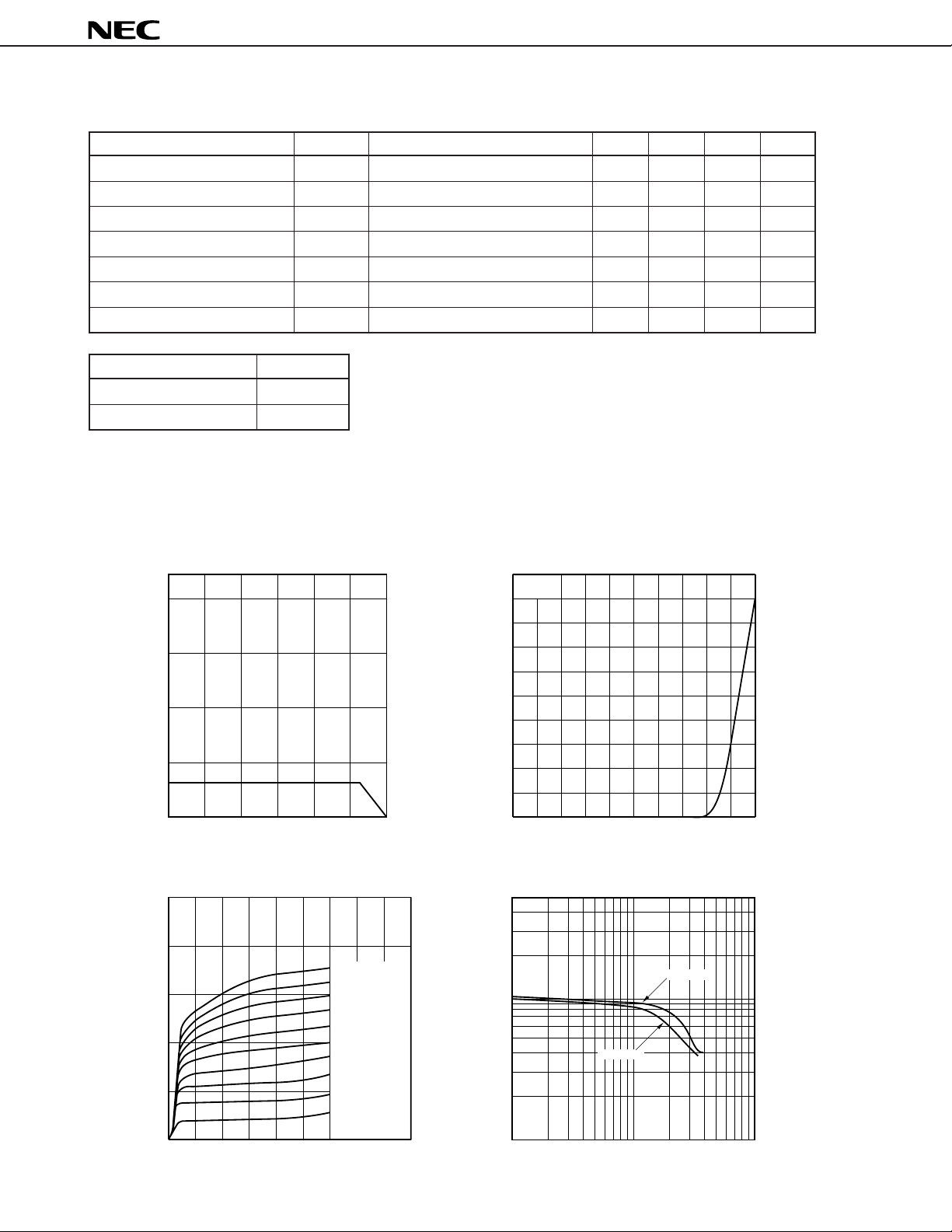
TYPICAL CHARACTERISTICS (TA = 25 °C)
TOTAL POWER DISSIPATION
vs. AMBIENT TEMPERATURE
200
100
- Total Power Dissipation - mW
T
P
0
50
A
- Ambient Temperature - °C
T
COLLECTOR CURRENT
vs. COLLECTOR TO EMITTER VOLTAGE
25
20
15
10
- Collector Current - mA
C
I
5
30 mW
100 150
200 A
µ
180 A
µ
160 A
µ
µ
140 A
µ
120 A
µ
100 A
µ
80 A
µ
60 A
µ
40 A
µ
I
B =
20 A
COLLECTOR CURRENT
vs. BASE TO EMITTER VOLTAGE
50
V
CE =
2 V
40
30
20
- Collector Current - mA
C
I
10
0
BE
- Base to Emitter Voltage - V
V
DC CURRENT GAIN vs.
500
COLLECTOR CURRENT
200
100
50
- DC Current Gain
FE
h
20
0.5 1.0
V
CE =
V
CE =
1 V
2 V
0
1.0 2.0 3.0
VCE - Collector to Emitter Voltage - V
10
1
2 5 10 20 50 100
I
C
- Collector Current - mA
2
Page 3
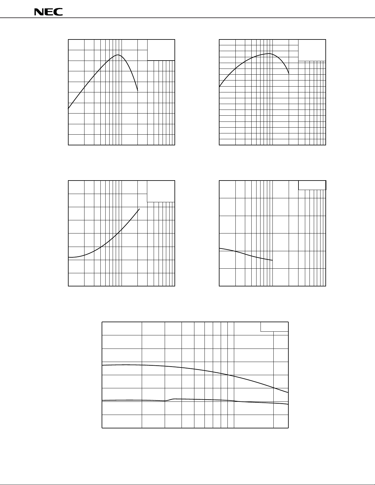
T
q
vs. IC characteristics
f
20
10
- Gain Bandwidth Product - GHz
T
f
VCE = 2 V
f = 2 GHz
21e
|2 vs. IC characteristics
|S
18
16
14
12
10
8
6
- Insertion Power Gain - dB
2
|
4
21e
|S
2
2SC5408
VCE = 2 V
f = 2 GHz
0.3
0
I
C
- Collector Current - mA
C
re
vs. V
CB
f = 1 MHz
0
1 10 100 1 10 100
C
- Collector Current - mA
I
C
NF vs. I
characteristics
4
VCE = 2 V
f = 2 GHz
3
0.2
2
NF - Noise Figure - dB
1
0
110
I
C
- Collector Current - mA VCB - Collector to Base Voltage - V
100 1 10 100
|S
21e
|2 vs. f characteristics
0.1
- Feed-back Capacitance - pF
re
C
0
40
VCE = 2 V
30
20
- Insertion Power Gain - dB
2
10
|
21e
|S
0
0.1 0.5 1.0 2.0 2.6
f - Fre
uency - GHz
C
= 7 mA
I
I
C
= 1 mA
3
Page 4

S PARAMETER
VCE = 2 V IC = 1 mA
FREQUENCY S 11 S21 S12 S22
MHz MAG ANG MAG ANG MAG ANG MAG ANG
100.000 0.969 –4.1 3.345 174.9 0.006 84.6 0.991 –3.2
200.000 0.967 –8.2 3.287 170.3 0.012 82.8 0.993 –6.8
300.000 0.959 –12.3 3.334 165.9 0.018 79.0 0.990 –10.0
400.000 0.952 –16.6 3.361 161.4 0.024 75.8 0.990 –13.6
500.000 0.943 –20.8 3.280 156.3 0.031 71.8 0.980 –17.3
600.000 0.931 –25.2 3.307 151.2 0.036 68.4 0.971 –20.8
700.000 0.919 –29.5 3.286 146.9 0.042 64.5 0.963 –24.2
800.000 0.903 –34.1 3.278 141.6 0.047 61.0 0.952 –28.1
900.000 0.883 –38.6 3.268 136.4 0.052 57.0 0.940 –31.6
1 000.000 0.865 –42.9 3.226 132.3 0.057 53.4 0.927 –35.3
1 100.000 0.842 –47.4 3.197 127.4 0.060 49.9 0.913 –38.8
1 200.000 0.817 –51 9 3.175 122.4 0.065 46.0 0.901 –42.6
1 300.000 0.796 –56.6 3.127 118.2 0.067 42.8 0.885 –46.2
1 400.000 0.774 –61.3 3.077 113.1 0.070 39.4 0.863 –49.6
1 500.000 0.748 –66.2 3.059 108.5 0.072 36.6 0.852 –53.2
1 600.000 0.725 –71.1 3.047 103.9 0.073 33.5 0.836 –56.8
1 700.000 0.702 –76.1 2.978 99.4 0.074 30.8 0.824 –60.0
1 800.000 0.678 –81.1 2.920 95.4 0.075 28.1 0.808 –64.0
1 900.000 0.653 –86.3 2.920 90.5 0.074 25.7 0.794 –67.2
2 000.000 0.633 –91.5 2.856 86.3 0.074 23.5 0.780 –70.8
2 100.000 0.611 –97.3 2.834 82.0 0.074 21.1 0.771 –74.1
2 200.000 0.591 –102.9 2.795 77.6 0.073 19.0 0.756 –77.6
2 300.000 0.571 –108.8 2.751 73.0 0.072 16.9 0.748 –81.4
2 400.000 0.554 –114.9 2.713 68.6 0.071 15.0 0.744 –85.0
2 500.000 0.535 –120.7 2.656 64.2 0.068 13.6 0.733 –88.5
2 600.000 0.520 –127.0 2.619 59.7 0.065 12.7 0.727 –91.6
2SC5408
VCE = 2 V IC = 7 mA
FREQUENCY S 11 S21 S12 S22
MHz MAG ANG MAG ANG MAG ANG MAG ANG
100.000 0.828 –9.4 15.424 169.5 0.005 82.0 0.969 –5.9
200.000 0.806 –18.5 14.864 160.4 0.011 77.6 0.951 –11.9
300.000 0.765 –27.2 14.467 151.7 0.016 72.4 0.920 –17.2
400.000 0.722 –35.7 13.904 143.2 0.020 67.5 0.892 –22.0
500.000 0.675 –43.3 12.879 135.6 0.024 62.8 0.846 –26.7
600.000 0.625 –50.8 12.259 127.9 0.028 59.6 0.809 –30.5
700.000 0.575 –57.8 11.555 121.5 0.030 56.6 0.772 –33.9
800.000 0.527 –64.6 10.806 115.1 0.033 54.4 0.738 –37.6
900.000 0.481 –70.9 10.151 109.2 0.035 52.6 0.708 –40.2
1 000.000 0.439 –77.0 9.573 104.2 0.037 51.0 0.678 –42.9
1 100.000 0.400 –82.9 8.988 99.2 0.038 50.0 0.650 –45.4
1 200.000 0.364 –89.1 8.510 94.4 0.039 49.3 0.628 –47.9
1 300.000 0.335 –95.3 8.017 90.2 0.041 48.9 0.611 –50.3
1 400.000 0.309 –101.6 7.572 85.8 0.042 48.9 0.589 –52.4
1 500.000 0.284 –108.2 7.203 82.0 0.043 48.7 0.575 –54.8
1 600.000 0.264 –115.1 6.876 78.1 0.044 49.5 0.563 –57.4
1 700.000 0.249 –122.5 6.569 74.1 0.046 49.4 0.553 –59.5
1 800.000 0.239 –129.9 6.225 70.9 0.047 50.1 0.541 –62.4
1 900.000 0.226 –138.1 6.019 67.4 0.048 50.8 0.532 –64.7
2 000.000 0.222 –145.1 5.728 63.8 0.050 50.9 0.525 –68.0
2 100.000 0.220 –154.2 5.541 60.6 0.052 51.9 0.519 –70.5
2 200.000 0.220 –161.9 5.326 57.0 0.054 52.3 0.511 –73.1
2 300.000 0.223 –169.9 5.112 53.7 0.056 52.5 0.511 –76.3
2 400.000 0.230 –176.7 4.951 50.6 0.059 53.1 0.510 –79.8
2 500.000 0.235 176.3 4.761 47.3 0.062 53.1 0.510 –83.1
2 600.000 0.245 169.7 4.602 43.9 0.065 53.0 0.513 –86.4
4
Page 5

[MEMO]
2SC5408
5
Page 6

[MEMO]
2SC5408
6
Page 7

[MEMO]
2SC5408
7
Page 8

2SC5408
No part of this document may be copied or reproduced in any form or by any means without the prior written
consent of NEC Corporation. NEC Corporation assumes no responsibility for any errors which may appear in
this document.
NEC Corporation does not assume any liability for infringement of patents, copyrights or other intellectual property
rights of third parties by or arising from use of a device described herein or any other liability arising from use
of such device. No license, either express, implied or otherwise, is granted under any patents, copyrights or other
intellectual property rights of NEC Corporation or others.
While NEC Corporation has been making continuous effort to enhance the reliability of its semiconductor devices,
the possibility of defects cannot be eliminated entirely. To minimize risks of damage or injury to persons or
property arising from a defect in an NEC semiconductor device, customers must incorporate sufficient safety
measures in its design, such as redundancy, fire-containment, and anti-failure features.
NEC devices are classified into the following three quality grades:
"Standard", "Special", and "Specific". The Specific quality grade applies only to devices developed based on a
customer designated "quality assurance program" for a specific application. The recommended applications of
a device depend on its quality grade, as indicated below. Customers must check the quality grade of each device
before using it in a particular application.
Standard: Computers, office equipment, communications equipment, test and measurement equipment,
audio and visual equipment, home electronic appliances, machine tools, personal electronic
equipment and industrial robots
Special: Transportation equipment (automobiles, trains, ships, etc.), traffic control systems, anti-disaster
systems, anti-crime systems, safety equipment and medical equipment (not specifically designed
for life support)
Specific: Aircrafts, aerospace equipment, submersible repeaters, nuclear reactor control systems, life
support systems or medical equipment for life support, etc.
The quality grade of NEC devices is "Standard" unless otherwise specified in NEC's Data Sheets or Data Books.
If customers intend to use NEC devices for applications other than those specified for Standard quality grade,
they should contact an NEC sales representative in advance.
Anti-radioactive design is not implemented in this product.
M4 96.5
2
 Loading...