

Page 1

H-8308p
Operator’s Manual
Page 2

Page 3

Copyright Information
CG Triumvirate is a trademark of Agfa Corporation.
CG Times based upon Times New Roman under license from the Monotype Corporation.
Windows is a registered trademark of the Microsoft Corporation.
Ethernet is a registered trademark of Xerox Corporation.
All other brand and product names are trademarks, service marks, registered trademarks,
or registered service marks of their respective companies.
Limitation of Liability
In no event shall Datamax-O’Neil be liable to the purchaser for any indirect, special or
consequential damages or lost profits arising out of or relating to Datamax-O’Neil’s
products, or the performance or a breach thereof, even if Datamax-O’Neil has been advised
of the possibility thereof. Datamax-O’Neil’s liability, if any, to the purchaser or to the
customer of the purchaser hereunder shall in no event exceed the total amounts paid to
Datamax-O’Neil hereunder by the purchaser for a defective product.
In no event shall Datamax-O’Neil be liable to the purcha ser for any damages resulting from
or related to any failure or delay of Datamax-O’Neil in the delivery or installation of the
computer hardware, supplies or software or in the performance of any services.
Some states do not permit the exclusion of incidental or consequential damages, and in
those states the foregoing limitations may not apply. The warranties here give you specific
legal rights, and you may have other legal rights which vary from state to state.
Firmware (Software) Agreement
The enclosed Firmware (Software) resident in the Printer is owned by Licensor or its
suppliers and is licensed for used only on a single printer in the user’s Trade or Business.
The User agrees not to, and not to authorize or permit any other person or party to
duplicate, or copy the Firmware or the information contained in the non-volatile or
programmable memory. The firmware (Software) is protected by applicable copyright
laws and Licensor retains all rights not expressly granted. In no event will Licensor or its
suppliers be liable for any damages or loss, including direct, incidental, economic, special, or
consequential damages arising out of the use or inability to use the Firmware (Software).
Information in this document is subject to change without notice and does not represent a
commitment on the part of Datamax-O’Neil Corporation. No part of this manual may be
reproduced or transmitted in any form or by any means, for any purpose other than the
purchaser’s personal use, without the expressed written permission of Datamax-O’Neil
Corporation.
All rights reserved
Copyright © 2014, Datamax-O’Neil
Part Number 88-2368-01, Revision A
Page 4

Agency Compliance and Approvals
C US
Listed
FCC: This device complies with FCC CFR 47 Part 15 Class A.
Note: This equipment has been tested and found to comply with the limits for a Class A digital
device, pursuant to Part 15 of the FCC Rules. These limits are designed to provide reasonable
protection against harmful interference when the equipment is operated in a commercial
environment. This equipment generates, uses, and can radiate radio frequency energy, and if
not installed and used in accordance with the instructions in this manual, it may cause harmful
interference to radio communications. Operation of this equipment in a residential area is likely
to cause harmful interference in which case the user will be required to correct the interference
at their own expense.
UL60950-1: 2007 2nd Edition Information Technology Equipment
CSA C22.2 No. 60950-1-07 2nd Edition
The manufacturer declares under sole responsibility that this product conforms to the
following standards or other normative documents:
EMC: 2004/108/EC
EN 55022 (2006, A1 :2007) Class A
EN 50024 (1998, A1:2001, A2:2003)
Safety: This product complies with IEC 60950-1, 2nd Edition, 2007-03-27
ROHS: 2002/95/EC
LVD: 2006/95/EC
Page 5

Important Safety Instructions
The exclamation point within an equilateral tr iangle is intended to alert you to
the presence of important operating and maintenance instructions.
This unit has been carefully designed to provide years of safe, reliable performance. As with
all electrical equipment, however, there are some basic precautions that you should follow
to avoid personal injury or printer damage:
Before using the printer, carefully read all the installation and operating instructions.
Observe all warning instruction labels on the printer.
Install the printer on a flat, firm surface.
Do not place the printer upon or near a heat source.
Never insert anything into the ventilation slots and openings of the printer.
Do not use the printer near water or spill liquid into it.
Ensure that the AC power source matches the ratings listed for the printer. (If
unsure, check with your dealer or local utility provider.)
Do not step on the AC power cord. If the AC power cord becomes damaged or
frayed, replace it immediately.
If the printer needs repair, consult only qualified, trained service personnel. No user-
serviceable parts are inside; do not remove the cover.
Special Instructions
The green check box is intended to alert you to notable details regarding
printer operation or to conventions used within this manual.
Page 6

Page 7

Contents
1 Overview ....................................................................................... 1
1.1 About the Printer ............................................................................... 1
1.1.1 Standard Features .................................................................... 1
1.1.2 Optional Features ..................................................................... 3
2 Getting Started .............................................................................. 5
2.1 Unpacking ........................................................................................ 5
2.1.1 Additional Requirements ........................................................... 6
2.2 Installation ....................................................................................... 6
2.2.1 Connecting the Power Cord ....................................................... 6
2.2.2 Connecting an Interface Cable .................................................... 7
3 Setting up the Printer .................................................................... 9
3.1 Media Loading .................................................................................... 9
3.1.1 Internal Media Sources ........................................................... 11
3.1.2 External Media Sources .......................................................... 13
3.2 Media Sensor Adjustment ................................................................. 15
3.3 Ribbon Loading ............................................................................... 16
3.4 Configuring Media and Ribbon Settings ............................................... 19
3.4.1 Using Media and Ribbon IDs ..................................................... 19
3.4.2 Selecting Media and Ribbon Typ es ............................................. 19
3.4.3 Setting the Media and Ribbon Parameters Manually (Advanced) ..... 21
3.4.4 Load a Saved Media File .......................................................... 21
3.5 Print Driver Installation .................................................................... 22
i
Page 8

4 Using the Control Panel ............................................................... 25
4.1 Menu Overview ............................................................................... 25
4.2 Layout of the Display ........................................................................ 25
4.2.1 Three Button Panel ................................................................. 26
4.2.2 Home Screen ......................................................................... 26
4.3 Menu Functions ............................................................................... 28
4.3.1 System Information .............................................................. 28
4.3.2 Settings Report ...................................................................... 28
4.3.3 Network Report ...................................................................... 31
4.3.4 Extended Status ..................................................................... 31
4.3.5 Serial Report .......................................................................... 31
4.3.6 GPIO Report .......................................................................... 32
4.3.7 Fonts Report .......................................................................... 32
4.3.8 Feed Button ........................................................................... 32
4.3.9 Menu Button .......................................................................... 33
4.3.10 Basic Settings ...................................................................... 33
4.3.11 User Labels ......................................................................... 37
4.3.12 Advanced Settings ................................................................ 38
4.3.13 Media Settings ..................................................................... 46
4.3.14 Communications ................................................................... 47
4.3.15 Too ls .................................................................................. 51
4.3.16 Language ............................................................................ 64
4.3.17 Test .................................................................................... 65
ii
Page 9

5 Operating, Adjusting and Maintaining the Printer ....................... 71
5.1 Printhead Assembly Adjustments ....................................................... 71
5.1.1 Leveling Cam Adjustment ........................................................ 71
5.1.2 Printhead Pressure Adjustment ................................................. 73
5.2 Maintenance ................................................................................... 74
5.2.1 Cleaning the Printhead ............................................................ 75
5.2.2 Cleaning the Fan Filter ............................................................ 77
5.2.3 Cleaning the Interior Compartment ........................................... 77
5.2.4 Cleaning the Media Sensing Components ................................... 78
5.2.5 Cleaning the Platen and Assist Rollers........................................ 78
5.2.6 Cleaning the Ribbon Path Components ....................................... 79
5.2.7 Cleaning the Exterior Surfaces .................................................. 81
5.3 Replacing the Printhead .................................................................... 82
6 Troubleshooting .......................................................................... 85
6.1 Problem Resolution .......................................................................... 85
6.2 Tr o u b l e s h o o t i n g Pr i n t Q u a l i t y ............................................................... 87
6.3. Error a n d W a rnin g M e s s ages ................................................................ 88
7 Specifications .............................................................................. 91
7.1 General .......................................................................................... 91
7.2 Specifications .................................................................................. 92
7.3 Approved Media and Ribbon .............................................................. 94
Appendix A ...................................................................................... 97
iii
Page 10

iv
Page 11

Overview
1
1.1 About the Printer
Congratulations on your purchase of the H-Class H-8308p printer (hereafter referred to as
“the printer”). This manual provides information regarding printer setup, operation, and
care.
To print label formats, refer to the instructions provided with you r labeling software; or, if
you wish to write custom programs, a copy of the pw Series Programmer’s Manual can be
found on the Accessories CD-ROM and at our web site at http://www.datamax-oneil.com
As detailed below, available standard and optional features can meet all of your labeling
requirements.
1.1.1 Standard Features
Depending upon the model and type, the printer offers the following standard features:
Feature
Control Panel Security X
Default Configuration Restorable X
Diagnostic Display and Modes X
Die Cast Media Hub X
1
Page 12

Feature (continued)
Direct Thermal Printing X
Downloadable Firmware Upgrades X
DRAM Memory (MB) 64
Multi-Language Support X
Ethernet LAN X
Fault Handling with Reprint X
Flash Memory (MB) 64
Touchscreen Graphics Display X
Host-Accessible Memory X
IntelliSEAQ Printhead X
Internal Test & Configuration Labels X
Label Retract Control after Print X
Media Counters X
Media Tear Bar X
Option Hardware Auto-Detection X
On-Demand and Batch Printing X
Power-up Diagnostics X
Resident Multiple Setup and Restore X
Resident Option Hardware Diagnostics X
Scalable Font Engine X
Serial RS-232 Interface X
Text, Bar Code, Graphics, and Image Printing X
Time and Date Battery Backup X
Time Stamping X
USB (device) Interface, Version 2.0 X
2
Page 13

1.1.2 Optional Features
The following optional features are offered for the printer:
Wireless Ethernet
A WiFi Ethernet card with many features, including:
802.11b WiFi LAN standards-based technology
Integrated module with radio, baseband, MAC, and application processors
Built-in TCP/IP and UDP for flexible LAN connectivity options
Built-in Web server for drop-in LAN and internet con nectivity
Built in WEP security protocol
Integrated command interface that eliminates complicated softw a re drivers
External Media Rewinders
Precision-crafted, bi-directional rewinding mechanisms with device-dependant features:
DMXREW1 - accepts 1 to 4 inch (25 to 101 mm) diameter core that is up to 4.5
inches wide (114 mm), and rewinds to an 8-inch (203 mm) maximum outer
diameter at 10 inches per second.
DMXREW2 – accepts a 3-inch (76 mm) diameter core that is up to 9.5 inches wide
(241 mm), and rewinds to a 12-inch (304 mm) maximum outer diameter at 30
inches per second.
Internal Rewinder, Powered "Full Roll"
A motorized internal mechanism to wind printed labels, or pull the backing mat erial when
using a Peel and Present option, into to a maximum outer diameter roll of eight inches (203
mm).
3
Page 14
Media Cutter
A rotary-type device that cuts material with a maximum thickness of .01 inch (.254 mm)
into lengths as small as 1.25 inches (31.8 mm).
Peel and Present Mechanism, Standard (Internal Rewind required)
A device that peels labels from the backing material for immediate application, regulated by
previous label removal (Minimum label length is 1.5 inches [38 mm]).
Present Sensor
An output regulator that inhibits printing when a label is presented.
USB Host Ports
Interface ports that allow the printer to accept external USB memory devices for storing
graphics, label formats, fonts, and firmware; and that allow USB keyboard connections for
direct data input applications.
Thermal Transfer
A hub assembly that allows printing with ribbon for exceptional image clarity and durability,
as compared to most direct thermal media types.
Option Installation
The table below lists the experience needed to install the options described above. For more
information, contact your dealer or Datamax-O’Neil.
Option Installation
Option Recommended Installer
External Media Rewinder Operator
Internal Rewinder Operator
Media Cutter Operator
Peel and Present Mechanism Operator
Present Sensor Operator
USB Host Ports DMX Certified Technician
Thermal Transfer Operator
4
Page 15

Getting Started
2
2.1 Unpacking
The printer has been carefully packaged to prevent transit damage. (Inspect the container for
damage and, if evident, notify the shipping company before acceptance.)
After removing the packaging, check the contents of the shipment.
The following items are included:
Printer
Power Cord
Quick Start Guide
Accessories CD-ROM
Warranty Card
Any special or additionally purchased items
Save the carton and packing material for future use.
5
Page 16
2.1.1 Additional Requirements
Other items can also be needed for operation:
An interface cable (see Section 2.2.2);
Applicable media (see Section 7.3); and,
Applicable software (consult the Accessories CD-ROM, your dealer, or Datamax-O’Neil).
2.2 Installation
The printer features an auto-ranging power supply and several different interface types for
easy installation.
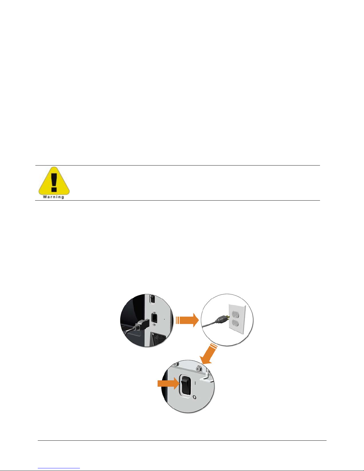
Ensure that the Power Switch is OFF when making printer connections.
2.2.1 Connecting the Power Cord
With printer placed upon a firm and level surface, connect the Power Cord as follows:
A. Ensure that the Power Switch is turned OFF.
B. Connect the Power Cord to the AC receptacle on the printer, and then to a properly
rated and grounded AC outlet.
6
Page 17

2.2.2 Connecting an Interface Cable
The printer can be interfaced to a host device via the Ethernet, USB or optional serial port.
Following power-up (or after inactivity), interface port select ion occurs automatically upon
detection of valid data.
To change an active port immediately, cycle the power OFF and ON.
•
Ethernet Connection
The Ethernet interface supports several menu-selectable modes. D epending on the length, the
cable should be Category / Type 3 or better.
USB Connection
The USB interface connection may differ slightly depending upon the operating system and
hardware configuration of the host computer.
Optional Serial Connection
The serial interface supports RS-232C communications RS-232C cabling configurations via
standard a null modem cable.
7
Page 18

8
Page 19
Setting up the Printer
3
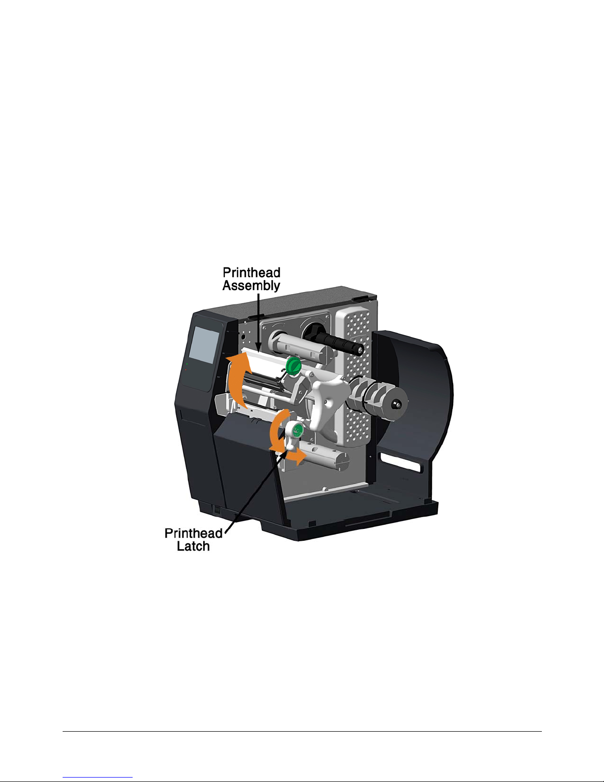
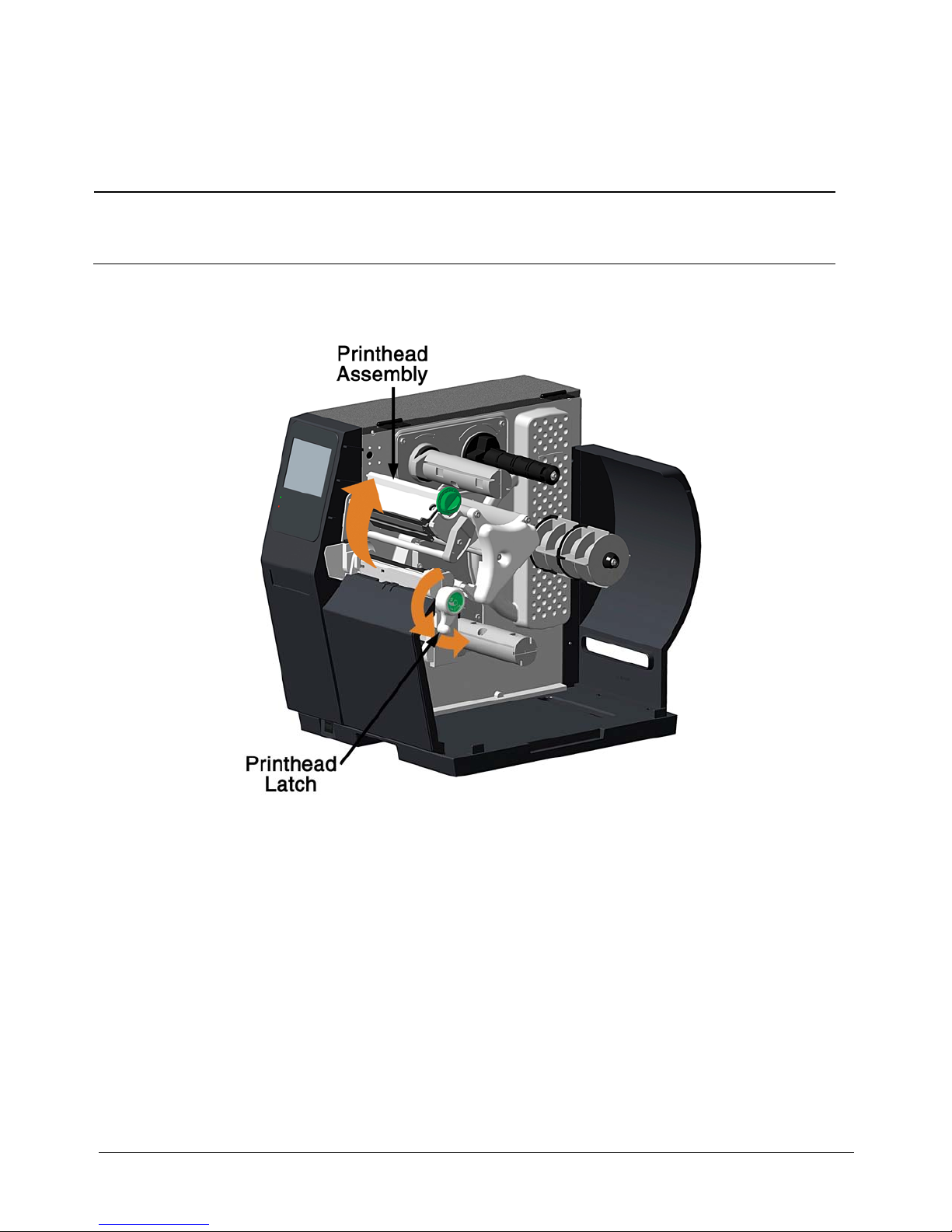
3.1 Media Loading
Load media according to its type and source, after performing these prerequisites:
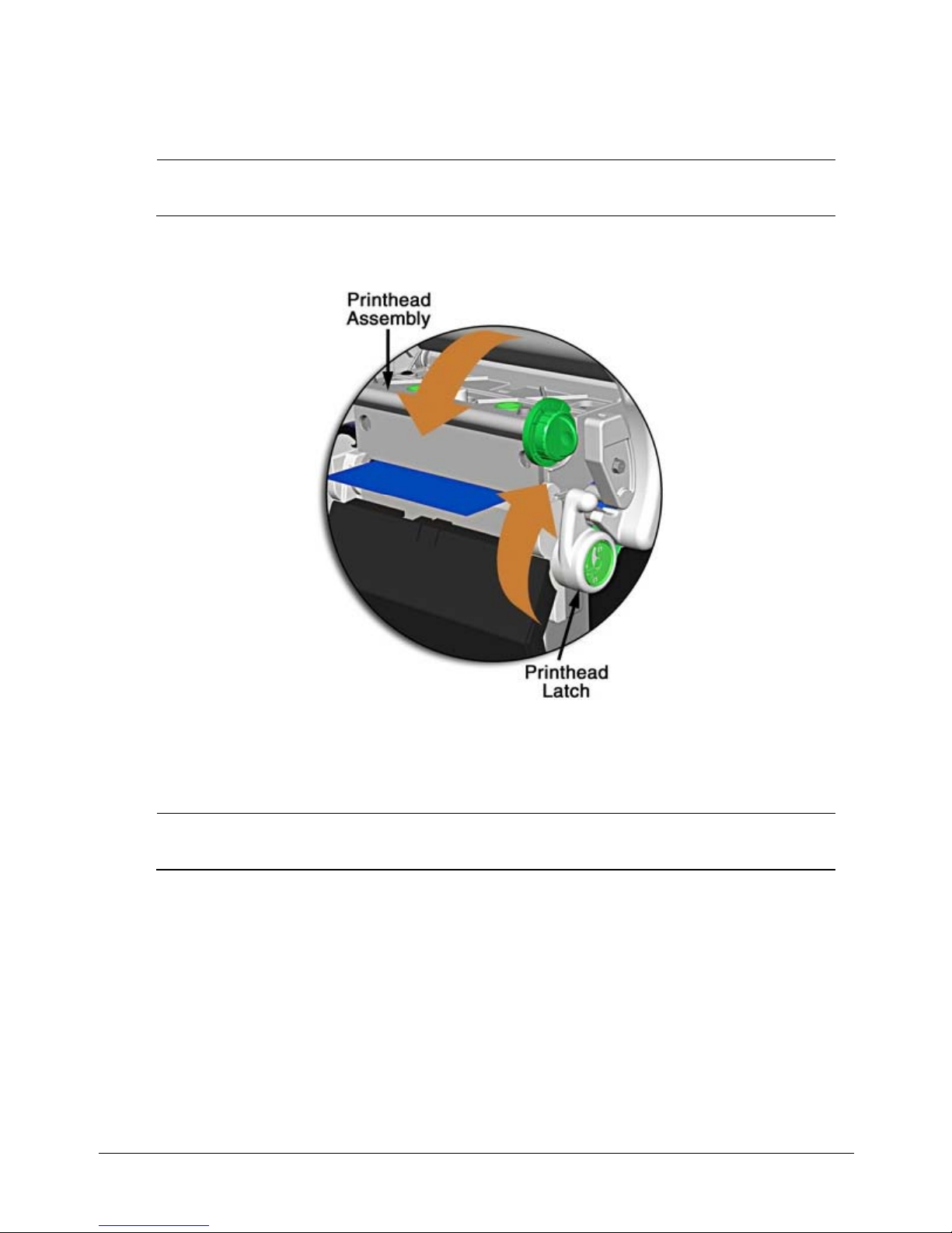
A. Raise the cover.
B. Rotate the Printhead Latch counterclockwise then raise the Printhead Assembly.
9
Page 20
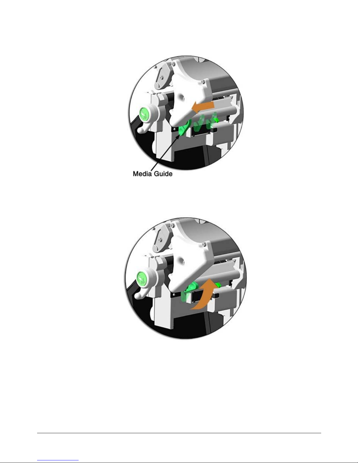
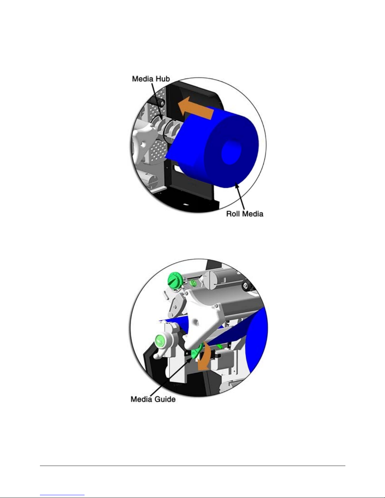
C. Slide the Media Guide ou tw ard.
D. Rotate the Media Guide upward.
E. Proceed according to the source of the media being installed:
• If using internally supplied (roll media) sources, see Section 3.1.1; or,
• If using externally supplied sources (e.g., boxed fanfold stock), see Section 3.1.2.
10
Page 21
3.1.1 Internal Media Sources
A. Slide Roll Media completely onto the Media Hub.
B. Route the media under the Media Guide Extrusion then out the front of the printer, as
shown.
C. Rotate the Media Guide into the DOWN position and then slide the guide inward until it
rests lightly against the edge of the media.
11
Page 22
D. If loading media for the first time, or if switching media types, widths, or configurations,
position the Media Sensor as detailed in Section 3.2; otherwise, go to Step E.
If loading thermal transfer media, also load ribbon; see Section 3.3.
E. Lower the Printhead Assembly then rotate the Printhead Latch completely clockwise.
F. Close the cover. With READY displayed, press the FEED Key until at least one gap (or
mark) advances.
If your media is less than the width of the printhead, adjust the Leveling
Cam; see Section 5.4.1.
12
Page 23
3.1.2 External Media Sources
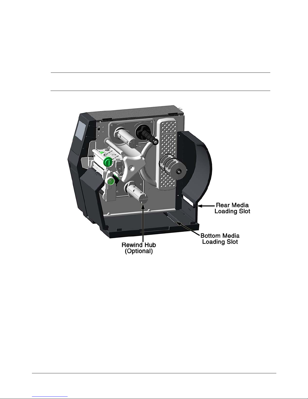
A. Place the media supply (box or roll) parallel to and in-line with the Rear Media Loading
Slot or Bottom Media Loading Slot, in a position that will not cause the media to twist or
turn as it feeds from the source.
If loading reflective media, be sure that the material enters the printer with
the black marks facing down.
B. Route the media into the printer through the Rear Media Loading Slot or Bottom Media
Loading Slot, and if equipped over the Rewind Hub.
C. Route the media under the Media Guide Extrusion then out of the printer, as shown in
the previous section.
D. Rotate the Media Guide into the DOWN position and then slide the guide inward until it
rests lightly against the edge of the media, as shown in the previous section.
13
Page 24
E. If loading media for the first time, or when switching media types, widths, or
configurations, position the Media Sensor as detailed in Section 3.2; otherwise, go to
Step F.
If loading thermal transfer media, also load ribbon; see Section 3.3.
F. Lower the Printhead Assembly then rotate the Printhead Latch completely clockwise.
G. Close the cover. With READY displayed, press the FEED Key until at least one gap (or
mark) advances.
If your media is less than the width of the printhead, adjust the Leveling Cam; see
Section 5.1.1.
14
Page 25

3.2 Media Sensor Adjustment
Position the Media Sensor for proper label detection:
A. Raise the Printhead Assembly. Note the Red Dot (see illustration below) th at identifies
the location of the Media Sensor.
B. Grasp the Slide Tab to position the Red Dot according to the Media Type, as detailed
below.
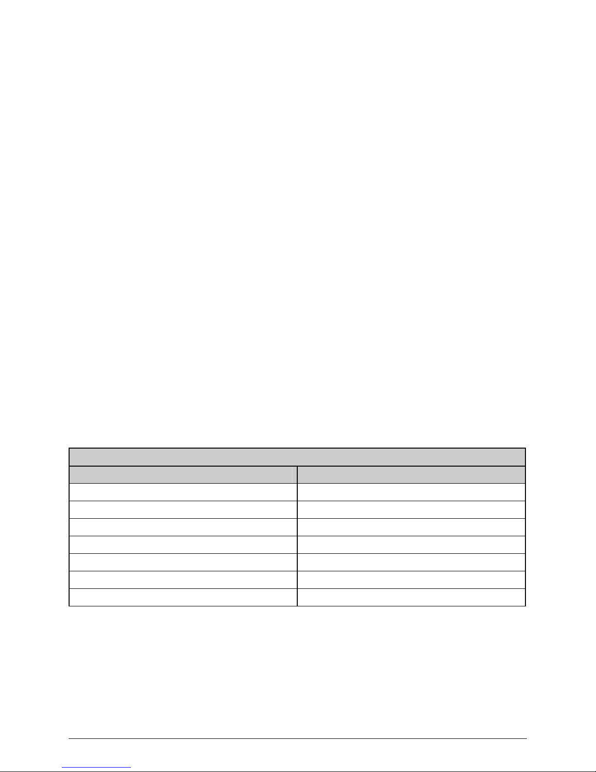
Media Sensor Adjustment
Media Type Red Dot Position
Die-cut Centered over a label
Notched Centered over a notch
Reflective Centered over a black mark
Continuous Centered over the material
C. Lower the Printhead Assembly then rotate the Printhead Latch completely clockwise.
D. If necessary, return to Media Loading to complete the setup process; otherwise, close
the cover. With READY displayed, press and hold the FEED Key until at least one gap (or
mark) advances; see Section 3.4.
If using REFLECTIVE or CONTINUOUS media, select the appropriate SENSOR TYPE;
see Section 3.4 Configuring Media and Ribbon Settings.
15
Page 26
3.3 Ribbon Loading
Ribbon, required when printing on thermal transfer media, should be loaded as follows:
The use of ribbon slightly wider than the media (and liner, if any) is recommended
to help protect against abrasive wear.
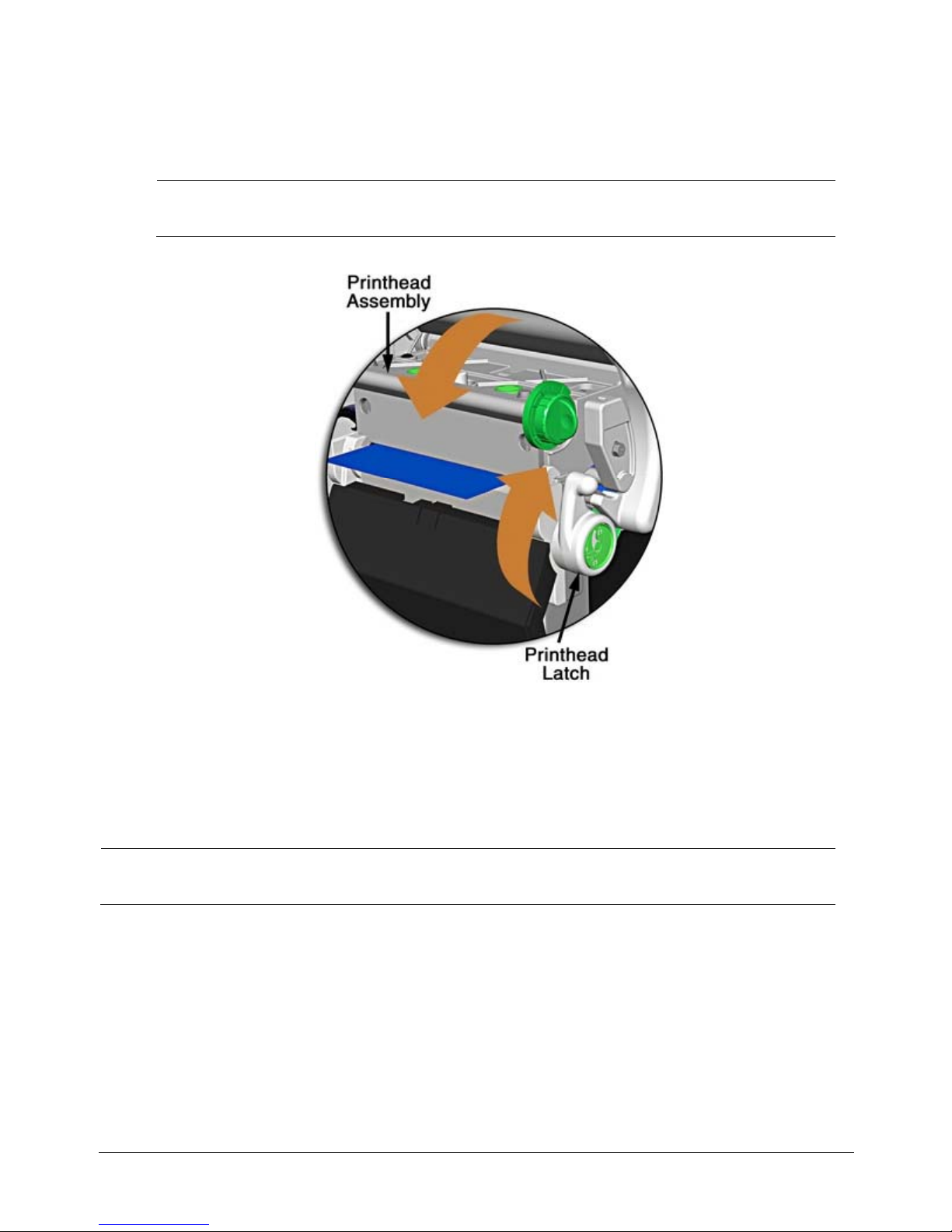
A. Rotate the Printhead Latch counterclockwise then raise the Printhead Assembly.
16
Page 27
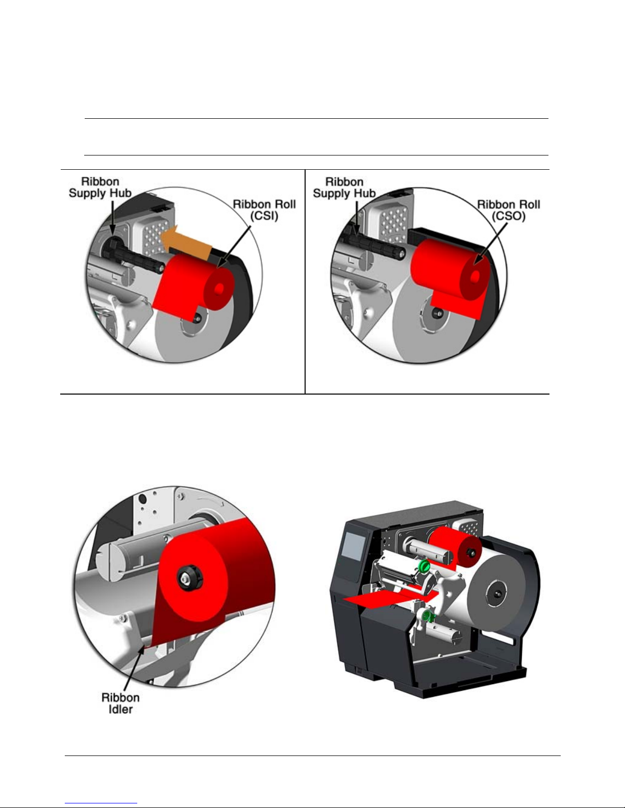
B. In the direction appropriate for the ribbon type being installed (Coated Side In or
Coated Side Out), slide a Ribbon Roll completely onto the Ribbon Supply Hub, as shown
below.
The coated (inked) side of the ribbon must face the media.
Coated Side In (CSI) Ribbon Coated Side Out (CSO) Ribbon
C. Route the ribbon under the Ribbon Idler then out the front of the printer.
17
Page 28
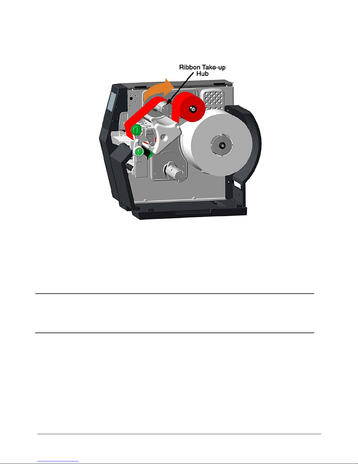
D. Route the ribbon up and around the Ribbon Take-Up Hub. Wrap the ribbon several
times clockwise (as indicated by the directional arrows) around the hub to secure it.
E. Lower the Printhead Assembly then rotate the Printhead Latch completely clockwise.
F. Close the cover. With READY displayed, press the FEED Key until at least one gap (or
mark) advances.
Remove used ribbon when the Ribbon Roll is depleted: Pull the empty core from the
Ribbon Supply Hub. Grasp the used roll on Ribbon Take-Up Hub then pull and
squeeze to remove the spent ribbon. (To remove partially depleted rolls, cut the
ribbon then remove the roll as described above and discard any used ribbon.)
18
Page 29

3.4 Configuring Media and Ribbon Settings
Once the media and ribbon have been loaded, the print parameters should be set to match
the type of media and ribbon being used. This will ensure optimal print quality.
the parameters will not need to be set again unless the media or ribbon types are changed.
3.4.1 Using Media and Ribbon IDs
Media and ribbons supplied by Datamax-O’Neil and other vendors may have up to an eight
(8) digit media ID and ribbon ID assigned. These codes may be created in the Utility menu
and then selected from Media menu via the printer’s front panel. All relevant print
parameters will be automatically configured.
1. Select Menu > Basic > Media > Media ID .
2. Using the up and down arrows, select the appropriate Paper ID. Note: No Media IDs
are provided by the factory.
3. T o select the Ribbon ID, navigate to tab 2 and use the scroll arrows to highlight and
select the appropriate Ribbon ID.
Once set,
4. Select the Home button.
5. After selecting the Home button, select the green Accept button to again confirm
your selection or the red Reject button to cancel the changes.
Note: Although using media and ribbon IDs usually produce very good results, minor
adjustments may be required. Refer to the section ti tled Adjusting Media and Ri bbon
Settings.
3.4.2 Selecting Media and Ribbon Types
If media and ribbon IDs are not known, the media and ribbon types may be selected manually.
1. Select Menu > Basic > Medi a > Sel ec t Type.
2. Using the up and down arrows, select your paper type.
Note: If the paper type is not known, either select Coated Direct Thermal for direct
thermal printing or select Coated Thermal Transfer for printing with a ribbon.
3. Ta b to the Ribbon screen.
4. Using the up and down arrow, select your ribbon type.
Note: If the ribbon type is not known, select Wax to start. This selection can always be
changed if required.
5. Ta b to the Settings screen.
19
Page 30

6. Select the Paper Sensor Type button until your paper type appears. The options
are as follows:
Gap
Mark on Bottom
Notch
Continuous
Note: For more information, refer to the section “Top-of-Form Sensor.”
7. Select the Ribbon Mode button until the correct option appears. The options are as
follows:
None
Coated In (CSI)
Coated Out (CSO)
Note: For more information, refer to the section “Top-of-Form Sensor.”
Note: CSI ribbon (shiny side facing outward) should be installed where the ribbon unwinds in
a counter-clockwise direction. CSO ribbon (dull side facing outward) should be installed where
the ribbon unwinds in a clockwise direction. If these settings do not match the ribbon type
being used, the ribbon supply hub will turn in the wrong direction.
20
Page 31

3.4.3 Setting the Media and Ribbon Parameters Manually (Advanced)
There are t imes when all prin t parameters must be set manually. Thi s can happen when a
new or specialized media or ribbon is being used. This advanced procedure will use the
Custom Manual utili ty.
Note: Some values may be grayed-out, meaning they are automatically set by default or not
available for the particular printer model. To change these values, select the Auto button next
to the value field and then select the green Accept button to confirm your choice to change to
manual mode.
Note: Please see the Menu section for more information.
1. Select Menu > Advanced > Med ia.
2. Select the Paper Sensor Type field until the correct paper type appears. The
options are as follows:
Gap
Mark on Bottom
Notch
Continuous
3. Select the Ribbon Mode field until the correct option appears. The options are a s
follows:
None - for direct thermal printing
Coated In - for thermal transfer printing
Coated Out - for thermal transfer printing
4. Ta b to the next screen and enter values for Heat and Heat Balance.
5. Ta b to the next screen and enter values for Rewinder Tension.
6. Ta b to the next screen and enter a value for Ribbon Low Diameter.
7. Select the Home button and select the green Accept button to confirm the settings.
3.4.4 Load a Saved Media File
For media and ribbon settings that are frequently used, media setup files can be saved to the
printer’s internal memory for easy access. For more information on saving the user setup files,
refer to the section titled Setups from the Tools > User Files menu section. To select an
internally saved media setup file, perform the following steps:
1. Select Menu > Basic > Media > User Media.
2. Using the up and down arrows, select the appropriate Internal Media Setup File.
3. Select the green Accept button and confirm the settings.
21
Page 32

3.5 Print Driver Installation
The Windows driver is located on the Accessories CD-ROM included with the printer. For the
latest version please visit our web site at http://www.datamax-oneil.com.
Installing the Windows Driver:
1. Place the Accessories CD-ROM included with the printer into the computers CD- ROM drive.
Once the CD-ROM starts select your printer model then “Install Driver” from the menu. Follow
the instructions on the screen to install.
If the driver was downloaded from our website, simply double click the downloaded “.exe” file
to launch the installation.
2. Check the “Install printer drivers” radio button then click
‘Next’ and follow the on-screen instructions to install the
driver.
3. When prompted, select your printer from the list, (i.e.
Datamax-O’Neil H-8308p). Continue to follow the on-screen
instructions to install the driver.
22
Page 33

Important Notes:
The Windows driver functions the same as any other Windows printer. While bu ilt-in help files
provide information on all settings, there are some important setting parameters that should
be observed for trouble free printing:
Page Setup Tab: Stock
It is important that the Stock setting matches
the size of the label you are using. If you
cannot find a match for your label click New
and enter the dimensions of your label.
Options Tab: Print Speed & Printhead Temperature
These two settings will have the greatest
effect on print quality. Some label stocks will
require more heat and slower print speeds to
generate a quality image.
The Windows application software used to create the label format will likely have a "Page
Setup" screen. This will also need to match the size of the label you are using.
23
Page 34

24
Page 35

Using the Control Panel
4
4.1 Menu Overview
The printer is designed with a touchscreen display. Functions can be enabled and disabled and
settings can be changed through the on-screen menu. Press the buttons on the screen with the
light touch of a finger.
Caution: Do not touch the screen with excessive force or by using sharp objects. Doing so will
damage the touchscreen and may void the manufacturer’s warranty.
4.2 Layout of the Display
The menu screens have buttons for advancing or returning to screens.
Back Button
The Back button provides the user with the option to return to a previous menu screen.
Home Button
Selecting the Home button sends the user to the main screen.
Tabbed Browsing
Blue left and right arrow buttons are provided at the bottom right of the screen to navigate
tabbed menus. Select the right arrow to advance to the next tab or the left arrow to return
to the previous tab.
Scrolling
Some menu screens allow for scrolling. Select the appropriate up or down arrow.
Changing Values
Numeric values can be entered or changed by selecting the field and entering the values
using the numeric keypad. They can also be increased or decreased using the subsequent
plus or minus buttons.
Other menu options are changed by pressing the button until the appropriate selection
appears.
Page Return Button
The Page Return button allows the user to return to the last setup screen that was exited
after selecting the Home button.
25
Page 36

4.2.1 Three Button Panel
The printer may be placed in 3-button security mode which restricts the operator from
changing any settings or printing test labels. An administrator can access the printer menu by
pressing on the “Model ID” in the taskbar and entering the appropriate security password.
Once the password has been entered and accepted, the user will be allowed access to th e full
home screen.
To return the menu to the 3-button security mode, select the “Model ID” again.
4.2.2 Home Screen
The home screen presents several options to the user.
Printer
Status
Operator Action
Area
Date / Time
Fault Information
Area
Model ID
Connected Devices
Mode Indicators
Buttons
Printer Stat us
The printer status area displays the state of the printer. These states include the following:
• Ready - The printer is idle and ready to accept internal or external c o mma nd s.
• Busy - Appears when printing or feeding paper.
• Fault - The printer has paused due to a fault condition.
• Warning - The printer has paused due to a warning indica tor.
• Cooling Down - The printer has paused while it is cooling down.
• Waiting - The printer is blocked by the optional Applicator or Present Sensor.
• Configuration - The printer is connected to the Configuration U tility .
• Canceling - The printer is currently canceling a p r int job .
and
26
Page 37

Operator Action Area
Informati on about the current printer action will be displayed in this area. For example, “Printing 1 of 3”
might be displayed when printing the first of three labels for a print job.
Date / Time
The time and date may be toggled on by pressing the upper right corner of the display. After pressing
the blank area, the current date and time will be displayed on the screen. Once the home button is
pressed, a screen will appear asking the user if t he date and time will be displayed. Select the green
Accept button to display the time or the red Reject button to cancel.
Fault Information Area
Warnings and fau lts wil l be displa yed in this area. Onc e the fault has been c orrected, the message will
disappear.
Connected Devices
The symbol for devices connected to the USB host will be presented in this area.
Mode Indicators
The printer will display modes that have been activated. If options have been installed but not
enabled, they will not appear in this area of the display.
Information Button
By selecting the information button from t h e t ask bar, the following information can be accessed. Select
the Print button in the taskba r to p r int the info r ma t io n. Not all of the information listed below is available
for every printer.
• System Info
• Settings Report
• Network Report
• Extended Status
• Serial Report
• GPIO Report
• Fonts Report
Note: Selecting the up or down arrow will display additional information.
27
Page 38

4.3 Menu Functions
4.3.1 System Information
The following will be dis p laye d upon selection of the System I n fo but t on:
• Printer Model
• Printhead Model
• Firmware Version
• FPGA Version
• Boot Versi on
• Board ID
• RAM Size
• Flash Size
• Printer Key
• Absolute Counter
• Printhead Counter
• Setup File
• Paper
• Ribbon
• Detected Options
4.3.2 Settings Report
The settings report provides information on the printer settings.
Media Settings
• Paper Sensor Type
• Ri bbon Mode
• Heat
• Heat Balance
• Rewinder Tension
• Ri bbon Low Di ameter
• Gap/Mark Offset
• Gap/Mark Noise
28
Page 39

Printer Settings
• Cutter Mode
• Cut by Count
• Rewi nder Mode
• Present Sensor
• Print Speed
• Feed Speed
• Reverse Speed
• Present Distance
• Paper Out Warning
• Reprint on Error
• Present Timeout
• Pause Mode
Page Defaults Settings
• Print Length
• Print Width
• Vertical Offset
• Horizontal Offset
• Orientation
• Raster Mode
• Font Name (Number)
• Point Size
• Pitch Size
• Symbol Set
• Print Truncation
• Print on Gap/Mark
29
Page 40

Auto Settings
• Auto Option Detect
• Auto Present Distance
• Auto T ension
• Auto Speed Adjust
Adjustment Settings
• Present Distance Adjust
• Cut Distance Adjust
• Cutter Rotation Adjust
• Vertical Adjust
• Horizontal Adjust
• Rewinder Tension Adjust
• Darkness
• Contrast
Calibration Settings
• Paper Threshold
• Gap/Mark Threshold (for non-continuous sensor type)
• TOF Gain
30
Page 41

4.3.3 Network Report
The Network Report option provides information about the network on which the printer resides. The
following information is available:
• Ethernet IP
• Ethernet Subnet Mask
• Ethernet Gateway
• Ethernet MAC
• Ethernet DHCP
• Wireless IP*
• Wireless Subnet Mask*
• Wireless Gateway*
• Wireless SSID*
• Wireless MAC*
• Wireless DHCP*
• Hostname
*Available only if the wireless option is installed.
4.3.4 Extended Status
The Extended Status option provides sensor information including:
• Head T emperature
• Head Voltage
• Ri bbon Lev el
• Rewinder Level
• TOF Sensor
• Session Label Count
Extended Status is als o a va ila b le whe n p r int ing b y pre s s ing the icon in the mod e indicator area.
4.3.5 Serial Report
The serial report provides serial connectivity information including:
• Baud Rate
• Data Bits
• Stop Bits
• Parity
• Flow Control
31
Page 42

4.3.6 GPIO Report
The GPIO Report provides the following information:
• GPIO Mode
• Slew Speed
• Pulse Width
• Signal 1 - I/O, Function, Type
• Signal 2 - I/O, Function, Type
• Signal 3 - I/O, Function, Type
• Signal 4 - I/O, Function, Type
• Signal 5 - I/O, Function, Type
• Signal 6 - I/O, Function, Type
• Signal 7 - I/O, Function, Type
• Signal 8 - I/O, Function, Type
4.3.7 Fonts Report
The Fonts Report provides the font name and the font ID/typeface ID number. This includes both the
resident and user downloaded or imported fonts.
Note: The resident fonts are listed in the Appendix of this ma nua l.
Note: It is the user’s responsibility to obtain the a pp r opriate licenses for download ed or imported fonts .
4.3.8 Feed Button
Selecting the feed but to n will feed the media through the p rint me c han ism one lab el a t a time.
32
Page 43

4.3.9 Menu Button
The Menu button provides the user with access to the system settings and also allows for the enabling
of options. The Menu screen displays the following options:
• Basic
• User
• Advanced
• Tools
• Language
• Test
4.3.10 Basic Settings
Selecting the Basic button allows for access to the basic settings. These include the following:
• Printer Mode
• Media
• Print Adjust
Printer Mode
The printer is available wit h s everal options which are enabled or disabled via the P rinter screen. Three
of the modes cannot happen concurrently so the highest priority mode will take precedence. The order
is as follows:
1. Pause Mode (High)
2. Present Sensor Enable (Medium)
3. GPIO (Low)
a. Cutter Mode
The cutter supports the cutting of media into separate labels.
For printers with a print media cutter installed, select from the following Cutter Mode options:
• Off
• Cut By Label
• Cut By Job
• Cut By Count
Cut By Count enables the user to specify the number of labels printed prior to being cut.
By Count field and enter the number of labels to be printed.
33
Select the Cut
Page 44

b. Rewinder Mode
Rewinder Mode controls the operation of the powered internal labe l rewind er.
For printers with a print media rewinder installed, select from the following Rewinder Mode options:
• Off
• Clockwise
• Counter Clockwise
c. Present Sensor
The Present Sensor option controls the on-demand dispensing of labels.
To enable or disable the installed Present Sensor option, select or deselect the corresponding checkbox.
d. GPIO Mode
The GPIO Mode enables or disables the applicator function from the printer. For printers with an
applicator connected, select from the following settings:
• Off
• Custom
e. Pause Mode
The Pause Mode option allows the user to prompt for the next label.
To enable or disable the Pause Mode, select or deselect the corresponding checkbox.
Media
Selecting the media button allows th e user to change the print media and ribbon settings. The printer
may automatically set up certain parameters once the paper and ribbon types have been inputted
either using the Media ID or manual entry.
a. Media ID
The user can qualify various media and ribbon types and has assign an ID value to them. After pressing
the Media ID button, ID values can be selected which will configure the printer to the optimum print
settings.
1. Using the up and down arrows, select the appropriate Paper ID.
2. If applicable, tab t o t he Ribbon ID page and use the up and down arrows to highlight
the appropriate value.
3. Select the Home button and select either the green Accept button or the Red reject button.
34
Page 45

b. User Media
If media setup files have been stored internally or on a USB mass storage device connected to the USB
host, the files can be selecte d from this interface.
Using the up and down buttons, highlight the file and then select the green check button.
Note: The first tab displays files that have been saved inter n a l ly . The second ta b displays files from
the mass storage device attached to the USB host. User files may be printed by selecting the print
button in the taskbar.
Note: Further details are available in the Advanced section of the menu. Please refer to
section of the manual for more information.
c. Select Type
For print media types that have not been qualified by the printer manufacturer, the Select Type option
allows the user to manually enter the media and ribbon types. This will configure the printer to the
approximate print settings.
The interface has three tabs:
the Advanced
• Paper - Using the up and down arrows, highlight the appropriate paper to be used.
• Ribbon - Using the up and down arrows, highlight the appropriate ribbon to be used.
• Settings - Choose the appropriate settings for your media and ribbon types.
Note: Fine adjustments to print setting s ma y be required to impr ov e print qualit y. The Select Type utility
is designed to approximate the print settings.
Paper Sensor Type
Print media contains distinctive characteristics and those characteristics must be accounted for in the
settings to ensure finding Top-of-Form.
Select from the following options:
35
Page 46

Paper Sensor Typ e Paper Sensor Side
Gap Inside
Outside
Mark on Bottom Inside
Outside
Notch Inside
Outside
Continuous Inside
Outside
Ribbon Mode
The Ribbon Mode option allows the user to enable and disable Ribbon Mode and notes the type of
ribbon being used.
Ribbon Mode has three settings:
• Coated In (CSI) - for thermal transfer printing
• Coated Out (CSO) - for thermal transfer printing
• None - for direct thermal printing
Print Adjust
The Print Adjust selection allows for the adjustments of both the darkness and the contrast of print
quality as well as horiz ontal and vertical a djustment s .
Selecting the plus or minus buttons respectively increases or decreases the values.
Changes to the values may also be made by selecting the field and entering the appropriate values
using the numeric keypad. During printing the print adjust screen will be available via an icon in the
mode indicator area of the front display. When paused the icon will be accessible via the home screen
icon.
Note: Settings that use the word “Adjust” should be considered fine adju stmen ts and ar e not main
settings.
a. Darkness
The darkness adjustment is set within the range of -20 to +20. To increase darkness, adjust the
settings in a positive (+) direction.
1. Enter the appropriate value in the field.
36
Page 47

2. Upon exiting the Print Adjust panel, either select the green Accept button or the red Reject
button.
b. Contrast
The contrast adjustment is set within the range of -10 to +10. To increase contrast, adjust the settings in
a positive (+) direction.
1. Enter the appropriate value in the field.
2. Upon exiting the Print Adjust panel, either select the green Accept button or the red Reject
Button.
c. Vertical Adjust
The vertical adjustment is set within the range of -100 to +100 dots. To move the image down, adjust
the settings in a positive (+) direction.
1. Enter the appropriate value in the field.
2. Upon exiting the Print Adjust panel, either select the green Accept button or the red Reject
button.
d. Horizontal Adjust
The horizontal adjustment is set within the range of -100 to +100 dots. T o move the image to the
right, adjust the settings in a positive (+) direction.
1. Enter the appropriate value in the field.
2. Upon exiting the Print Adjust panel, either select the green Accept button or the red Reject
button.
4.3.11 User Labels
The user button allows for the usag e o f cu s t o m la be ls a n d c u st o m pr int e r c o nfigur a t io ns that are saved
internally or saved to a memory stick ins er ted in the USB hos t.
User Labels
Custom user labels that have been saved internally or in a mass storage device may be printed.
1. Select User Labels.
2. Select the file to be p r int ed (internally or USB hos t ed) .
3. Select the green Accept button.
4. Select the Print button to print the label.
Note: Further details are available in the Advanced section of the menu. Please refer to
section of the manual for more information.
the Advanced
37
Page 48

User Setups
Printer configurations that have been saved internally or on a mass storage de vice attached to the USB
host may be accessed and implemented from this utility.
1. Select User Setups.
2. Select the internally hosted user s etu p file.
3. Select the green Accept button.
Note: Further details are available in the Advanced section of the menu. Please refer to
section of the manual for more information.
the Advanced
4.3.12 Advanced Settings
The Advanced button provides access to the advanced settings of the printer. These settings include the
following:
• Page Defaults
• Printer
• Media
• Comm (com munications)
• Adjustments
Page Defaults
The following page parameters can be adjusted:
Settings Values Ranges Default
Print Length
Print Width
N/A
N/A
.10 to 99.00 in. 4.00 in.
Refer to the
Overview section
to find your
specific model
4.00 in.
Vertical Offset
Horizontal Offset
N/A
N/A
.00 to 10.00 in 0.00 in
.00 to 4.00 in 0.00 in
38
Page 49

Settings Values Ranges Default
Orientation Portrait
Landscape
Portrait
Reverse Portrait
Reverse Landscape
Raster Mode Transparent
Opaque
Opaque
Default Font Number (Please see Appendix A for
0 to 52 23 (Courier)
the appropriate values)
Default Symbol Set (Please see Appendix A for
[0] PC-8
the appropriate values)
Default Point Size
Default Pitch Size
Print Truncation Enabled
N/A
N/A
4.00 to 999.75 12.00
.44 to 99.99 10.00
Enabled
Disabled
Print on Gap Enabled
Disabled
Disabled
Note: The default settings will be used if the print job does not directly specify the settings.
Note: Most of these settings will affect the internal Quality Label from the Te st menu.
Note: Rotating oversized images with Print Truncation enabled may result in truncating the printout entirely.
Note: Setting the raster mode to transparent will allow for texts, barcodes and images that support transparency
to be copied onto the destination without the white regions generally associated with images. Setting the raster
mode to opaque allows for texts,
the source. Generally, this is only notices when text, barcodes or images are placed on top of each other.
Note: Print on Gap when enabled in Continuous paper mode eliminates simulated gap betwee n labels. In this
mode, vertical adjustment can be used to control the skip space size for different TOF types.
Note: Print Truncation takes precedence over Print on Gap.
barcodes and images to be applied onto the destination with the white pixels from
39
Page 50

Printer
The following settings may be adjusted:
• Presentation
• Auto
• Speeds
• Alarms
• Options
• Set Defaults
a. Presentation
The following settings can be adjusted.
Presentation Values Ranges Default
Pause Mode Enable
Disable
Present Time Out
Present Distance
Note: To manually change the Present Distance settings, select the Auto button to the left of the
value field and follow the instructions to enter and save the changes.
b. Auto
The printer has several Auto settings that can be enabled or disabled.
0 - 1000 s 0 (never)
0.00 - 4.00 Auto
Disable
Selection Values Default
Auto Option Detect Enable
Disable
Auto Present Distance Enable
Disable
Auto Tension Enable
Enable
Enable
Enable
Auto Speed Adjust Enable
Disable
Enable
Disable
40
Page 51
c. Speeds
The following settings may be adjusted:
• Print Speed
• Feed Speed
• Reverse Speed
Speed Settings Speed Range (IPS)
Print Speed
Feed Speed 2.0 - max speed; model dependent (Increments of
Reverse Speed 2.0 - max speed; model dependent (Increments of
2.0 - max speed; model dependent
(Increments of 0.5)
0.5) or Auto
0.5) or Auto
d. Alarms
The following alarm settings may be adjusted.
Adjustments Options Default
Paper Out Warning True
False
Reprint on Error True
False
True
True
41
Page 52

e. Options
The following settings may be adjusted:
• Cutter - Controls the cutting action of the media.
• GPIO - Controls the application of labels.
• Present Sensor - Controls the “on-demand” dispensing of labels.
• Rewinder - Controls the operation of the powered internal label rewinder.
Cutter
The following settings may be adjusted for printers with the cutter option installed:
Adjustments Options Ranges Default
Cutter Mode Off
Cut By Label
Cut By Job Cut
By Count
Cut By Count
Cut Distance Adjust
Cut Rotation Adjust
Note: *A positive value rotates the blade further.
-100 to 100 dots 0
-10 to 10* 0
Off
1
GPIO
The following settings may be adjusted for printers with the GPIO option installed:
Adjustments Values Ranges Default
GPIO Mode Off
Custom
Slew Speed
Pulse Width
2 - 10 IPS 8 IPS
1 - 2000μs 1000μs
Off
42
Page 53

Adjustments Values Ranges Default
I/O Configuration
Select Signal
Sig 1/2
Sig 3/4 Input
Sig 5/6 Input Output
Sig 7/8 Input Output
Input
Output
Output
Output
Output
Sig 1 None
Start of Print
Reprint Slew
Pause
Input
Input
Start of Print
Sig 2 None
Start of Print
Reprint Slew
Pause
Sig 3 None
Start of Print
Reprint Slew
Pause
Sig 4 Start of Print
Reprint Slew
Pause
Reprint
Slew
Pause
43
Page 54

Adjustments Values Ranges Default
Sig 5 End of Print
Data Ready
Media Low
Service
Sig 6 End of Print
Data Ready
Media Low
Service
Sig 7 End of Print
Data Ready
Media Low
Service
Sig 8 End of Print
Data Ready
Media Low
Service
End of Print
Data Ready
Media Low
Service
Signal Type
Sig 1 Low
Low Pulse
Hi Pulse
Sig 2 Low
Low Pulse
Hi Pulse
Sig 3 Low
Low Pulse
Hi Pulse
Sig 4 Low
Low Pulse
Hi Pulse
High
High
High
High
Low
Low
Low
Low
44
Page 55

Adjustments Values Ranges Default
Sig 5 Low
Low Pulse
Hi Pulse
Sig 6 Low
Low Pulse
Hi Pulse
Sig 7 Low
Low Pulse
Hi Pulse
Sig 8 Low
Low Pulse
Hi Pulse
High
High
High
High
Low
Low
Low
Low
Present Sensor
The following settings may be adjusted for printers with the present sensor option installed:
Present Sensor Settings Values Ranges Default
Present Sensor Enable
Disable
Present Distance Adjust
Note: For small labels, present distance must be set to 0 to avoid becoming stuck during backup.
Rewinder
The following settings may be adjusted for printers with the rewinder option installed.
Rewinder Settings Values Ranges Default
Rewinder Mode
Off
Clockwise
Counter Clockwise
-100 to 100 dots 0
Disable
Off
Rewinder Tension Adjust
-10 to 10 0
45
Page 56

f. Set Defaults
The factory default settings for the printer setup can be reset. To reset to the default settings, select
Set Defaults. Confirm your selection by selecting the green Accept button.
Note: If the current custom settings have not been saved but will be needed again, be sure to save
them with the User Files utility from the Tools menu before resetting to
defaults.
4.3.13 Media Settings
Select Media to change the print media settings.
Media Settings Values Ranges Default
Paper Sensor Type Gap
Mark on Bottom
Notch
Continuous
Ribbon Mode Coated In Coated
Out
None
Heat
Heat Balance
Rewinder Tension
Ribbon Low Diameter
Gap/Mark Offset
Gap/Mark Noise
Note: *These values may vary depending on the printer model.
1 to 30 5*
1 to 10 8*
1 to 20 12*
1.0 to 2.0 in. 1.5 in.
-12 to 12 0
0 to 600 0
Gap
Coated In
46
Page 57

4.3.14 Communications
Select Communications to change the communications settings.
a. Ethernet
The following Ethernet communications settings may be adjusted:
Functions Values Actions Default
DHCP Enabled
Disabled
IP Address
Subnet Mask
Gateway
Once the data has been entered, select the Home button and then select the green Accept button to
save the changes which will require a printer reboot.
If necessary, the user may return to the default settings by selecting General > Reset Default s >
Ethernet.
b. Wireless
The following wireless settings may be set for printers with the wireless option installed:
If DHCP is disabled, enter the appropriate
value
If DHCP is disabled, enter the appropriate
value
If DHCP is disabled, enter the appropriate
value
Enabled
0.0.0.0
0.0.0.0
0.0.0.0
Functions Values Actions Default
Wireless Enable Enabled
Enabled
Disabled
SSID
Wireless DHCP Enabled
IP Address
Subnet Mask
Disabled
Enter the appropriate SSID value 0.0.0.0
Enter the appropriate value 0.0.0.0
Enter the appropriate value 0.0.0.0
47
Enabled
Page 58

Functions Values Actions Default
Gateway
Security None
Password
Show Password Enabled
To return to the default settings, select General > Reset Defaults > Wireless.
c. Serial
The following tabbed option settings may be adjusted for printers with the Serial Interface option installed:
WEP
WPA
WPA2
Disabled
Enter the appropriate value 0.0.0.0
Enter the appropriate value
None
Disabled
• Baud Rate - Sets the serial communications rate in bits per second
• Data Bits - Sets the word length
• Stop Bits - Sets the number of stop bits
• Parity - Sets the word parity
• Protocol - Sets the serial communications handshaking mechanism, software, hardware
or none.
Functions Values Ranges Default
Baud Rate 9600
19200
38400
57600
115200
Databits 7
8
Stopbits 1
2
Parity
Protocol
None Even
Odd
None
Hardware
115200 BPS
8
1
None
None
To return to the default settings, select General > Reset Defaults > Serial.
48
Page 59

d. General
Select from the following to change the General communications settings:
Services
The following services may be enabled or disabled:
• Enable Network Time Protocol
• Enable Webpages
• Enable SSH (SSH-2 is supported)
• Enable SNMP
• SNMP Trap IP
• Enable LPD
To print using the LPD service, c onnect from a host using the LPR port and the queue name “lp”.
Services Default
Enable Network Time Protocol Disabled
Enable Webpages Enabled
Enable SSH Enabled
Enable SNMP Disabled
SNMP Trap IP 127.0.0.1
Enable LPD Enabled
Webpages provide a printer configuration interface for the user. Users can view the printer status, set
printer paramet ers, print test labels and perform simple actions like printer calibration and sett ing
defaults.
To access the printer Webpages from a computer where the printer has been installed, type the
printer’s IP address into the Web browser URL field.
Note: The printer must be connected to the Ethernet.
To find the IP address, select Info > Network Report and record the value for Ethernet IP.
Note: The following Web browsers are supported:
• Intern et Explorer (version 8 and higher)
• Firefox (version 13 and higher)
• Google Chrome (version 23 and higher)
49
Page 60

Host Settings
Select from the following to change the Host Settings.
Function Range Default
Host Timeout 1 to 300 seconds 1
Port Number 0 -65535 9100
Host Name Any String Printer model number followed by
the last 6 digits of the MAC
address. Ex: p1115_208CB7
Hex Transfer True/False False
Reset Defaults
The Reset Defaults function allows the user to reset the communications to the default settings.
T o reset the communication settings to the factory default settings, select one of the options and select
the green Accept button to make the change.
• Ethernet
• Wireless
• Serial
Adjustments
Adjustments are considered fine adjustments and should not be considered main settings. Select from
the following settings to change the values:
Adjustment Settings Ranges Default
Darkness -20 to 20 0
Contrast -10 to 10 0
Vertical Adjust -100 to 100 0
Horizontal Adjust -100 to 100 0
Rewinder Tension Adjust -10 to 10 0
Present Distance Adjust -100 to 100 0
Cut Distance Adjust -100 to 100 0
Note: Narrow labels may slip during backup if the head pressure is set too high.
50
Page 61

4.3.15 Tools
Select from the following options to adjust the appropriate settings:
• Calibrate
• Security
• Maintenance
• User Files
• Date/Time
Calibrate
The Calibrate settings include:
• Calibrate Sensors
• Calibrate Paper
• Calibrate Manually
• Calibrate Display
a.
Calibrate Sensors
Select Calibrate Sensors to automatically calibrate the printer without print media. Calibration includes
changes to the following settings:
• Head Pressure (n o t applicable for t h e p1115)
• Auto Load Sensor
• Top-of-Form Sensor
Note: The print media must be removed and the printhead mechanism must be unlatched for the
Calibrate Sensors to prop er ly c a librate the printer.
b.
Calibrate Paper
When selecting Calibrate Paper, the paper is scanned to determine the top-of-form media and top-ofform gap settings.
Upon selection, the printer will move the paper forward and backward over the gap or mark. It may be
helpful to place the identifying mark or notch just behind the TOF sensor so that the sensor will go over
the mark as the media progresses through the printer.
Calibrate Paper is intended to sample paper with t he d e f ault size of 4” x 4”. If a 4” x 6” label is used
for calibration and the TOF sensor is placed just after the identifying mark or notch, it may not calibrate
properly because it is designed to move the paper only 4”.
Note: Print media must be properly installed in the printer for the Calibrate Paper function.
Note: Manually selecting Calibrate Paper is not necessar y if Auto Calibration is enab led. Howeve r, it may
help in calibrating more difficult media.
51
Page 62

c.
Calibrate Manually
Intended for advanced users, the calibrate manua lly section allows the user to manually adjust the topof-form sensor for specialized media. The TOF ADC Reading field displays the current top-of-form sensor
reading for the currently selected paper type and sensor side.
The values for gain, paper threshold and gap/mark threshold are shown for the currently selected paper
type and sensor side as well. The se values are typically set when auto calibration is performed using the
Calibrate Paper utility.
The capture feature allows the user to lift the printhead, and using the LED as a guide place the
paper under the sensor and capture the value. Then, moving the gap (media backing) or mark under
the sensor, the value can be captured.
Note: Performing Calibrate Paper will overwrite the threshold values.
Select Calibrate Manually to change the following setting s:
• Top-of-Form Gain
• Paper Threshold
• Gap/Mark Threshold
Adjustment Settings Ranges
TOF Gain 1 to 31
Paper Threshold 0 to 255
Gap/Mark Threshold 0 to 255
d.
Calibrate Display
Select Calibrate Display and then select either the green Accept button to continue or the red Reject
button. Upon selecting to co ntinue, follo w the on-screen d irections to prop erly calibrate the
touchscreen display.
If the touchscreen display becomes unusable, the printer can be calibrated during power- up as well. To
calibrate during power-up, perform the following procedure beginning with the printer powered off.
1. Press and hold the Reset button on the back of the printer.
2. Toggle the power switch to power-on the printer.
3. Continue to hold the R e s et button for ten (10) seconds.
4. Follow the on-screen instructions to calibrate the display.
Note: Allow a few minutes for power-up to complete.
52
Page 63

Security
The security settings may be adjusted. These adjustments include changing the password as well as
changing the security level.
To change the password, perform the following steps:
1. Select Change Password.
2. Enter the old password using the on-screen keyboard.
3. Select the green Accept button to accept the entry or the red Cancel button to reject the entry.
4. Enter the new password and select either the green Accept button or the red Cancel
button.
5. Re-enter the new password and select either the green Accept button or t he red cancel
button.
To change the security level, choose from the following options:
Functions Options
Security Level Off Secure
Secure All
3 Button Display
Security Descriptions
• Secure - When the “Secure” option is selected, changes to the advanced settings and
user tools will require a password.
• Secure All - When the “Secure All” option is selected, changes to any settings will
require a password.
• 3 Button Display - When this option is selected, the three button display will be
enabled on the main panel. A password will be needed to access the menu again.
Note: The factory default password is the number “0.”
Note: By default, security should be disabled.
53
Page 64

Remove Security
T o remove security, select the lock icon to the right of the Change Password utility. Type your
password and then select the green Accept button. To confirm, select the green Accept button.
Maintenace
To adjust the following Maint e na nc e set ting s , se le c t the Maintenance button. The maintenance settings
include:
• Cleaning
• Upgrade
• Odometers
a.
Cleaning
Cleaning should be routinely performed. The maintenance alarm is set by the user in thousands of
inches.
Enter the desired maintenance reminder interval. Once a fault appears directing the user to clean the
printhead, insert a factory approved cleaning card under the printhead and select Clean Now.
The Elapsed field displays the number of inches, in thousands, since the last cleaning.
Maintenance Settings Ranges Actions Default
Maintenance 0k to 1000k in.
Clean Now
Select Clean Now
0 (never)
b.
Upgrade
The Upgrade function allows the user to upgrade the printer software. Insert a mass storage device
into the USB host with the appropriate file to be uploaded and then select Upgrade.
Do not turn off the printer during the process. Once the printer has been updated, it will reboot.
When the printer is back online, be sure t o power-cycle the printer once more by turn ing it off an d
then back on.
Note: Save all user files, labels and setups to a mass s torage device connected to the USB host
prior to updating your printer. Files that are not saved may be lost during the upgrade process.
Note: Upgrades may also be performed using the Configuration Utility.
54
Page 65

c.
Counters
The following Counter readings are viewed:
• Absolute
• Printhead
• User
Note: The printhead odometer will not display in this area. To reset the user odometer, select the Reset
User button.
User Files
The User Files utility allo ws the user to access files that are saved internally o r saved to a mass
storage device.
a. Labels
Labels can be saved either internally or to a mass storage device. These labels can also be printed from
this utility. Labels stored on a mass storage device must be placed in a directory called user_labels
at the root (top) level of the storage device (e.g.
E:\user_labels).
Note: Label names cannot contain a space character.
Print
The user can print label files that have been saved internally or saved to a mass storage device attached
to the USB host.
1. Select Print.
2. Using the scroll arrows, highlig ht the file to be printed.
Note: The first tab displayed in the interface reveals the files that have been saved internally. Tab 2
displays the available files from the attached mass storage device.
3. Select the green Accept button.
4. Select the printer icon in the taskbar.
55
Page 66

Organize
User labels may be copied from a mass storage device to the internal memory or from the internal
memory to a mass storage device. They may also be deleted or renamed from this utility.
Copy
1. Select Organize.
2. Using the scroll arrows, highlight the appropriate file.
3. Select the green Accept button to continue.
4. Select Copy.
5. Select the green accept button to copy the files between internal storage and the USB mass
storage device.
Delete
1. Select Organize.
2. Using the scroll arrows, highlight the appropriate file.
3. Select the green Accept button to continue.
4. Select Delete.
R
Rename
1. Select Organize.
2. Using the scroll arrows, highlight the appropriate file.
3. Select the green Accept button to continue.
4. Select Rename.
5. Confirm your selection by selecting the green Accept button.
6. Using the alpha-numeric keypa d, enter a new name for the selected file.
7. Select the green Accept button to continue.
b. Media
The Media utility allows the user to copy, delete and rename media config ur a t ion files. It also
provides access to setup files stored internally or on a mass storage device connected to the USB
host. The user can also save the current media configuration setup. Media configuration files that are
stored on a mass storage device must be placed in a directory called user_media at the root (top)
level of the storage devic e (e.g .
E:\user_media).
Note: Media names cannot contain a space character.
56
Page 67

The settings include the following:
• Media ID
• Ribbon ID
• Paper Sensor Type
• Ribbon Mode
• Heat
• Heat Balance
• Rewinder Tension
• Auto Tension
• Print Speed
Organize
To copy, delete or rename a file to or from a mass storage device connected to the USB host, perform
the following steps:
Copy
1.
Select Organ ize.
2. Using the scroll arrows, highlight the appropriate media configuration file.
3. Select the green Accept button to continue.
4. Select Copy.
5. Select the green Accept button to confirm.
Delete
1. Select Organize.
2. Using the scroll arrows, highlight the appropriate media configuration file.
3. Select the green Accept button to continue.
4. Select Delete.
5. Select the green Accept button to confirm.
R
N
57
Page 68

Rename
1. Select Organize.
2. Using the scroll arrows, highlight the appropriate media configuration file.
3. Select the green Accept button to continue.
4. Select Rename.
5. Using the alpha-numeric keypa d, enter a new name for the selected file.
6. Select the green Accept button to confirm.
Load
The Load utility allows the user to change the media configuration settings to a setup that was
previously saved internally o r to a mass storage device.
1. Select Load.
2. Using the scroll arrows, highlight the appropriat e media setup file.
3. Select the green Accept button.
4. Select the green Accept button to confirm.
Save Media Settings
The Media Setup utility allows the user to save the current media configuration settings internally.
1. Select Media Setup.
2. Select the green Accept button.
3. Using the alpha-numeric keypad, type a name for the setup file.
4. Select the green Accept button to confirm.
Save Media IDs
The Media Setup utility allows the user to save current media ID settings internally.
1. Select Media ID.
2. Using the alpha-numeric keypad, type the desired Paper ID.
3. Using the alpha-numeric keypad, type the desired Ribbon ID.
4. Select the green Accept button to confirm.
Note: Media ID files use and equal (=) sign to separate between paperID and ribbonID.
c. Setups
The User Setup utility allo ws for the user to c opy , delete and rename printer settings. The user can also
save the current setup and load a saved setup. User setup files stored on a mass storage device must be
placed in a directory called user_configs at the root (top) level of the storage device (e.g.
E:\user_configs).
These settings include the ones listed in the Setting Report from the Info menu and exclude
adjustments and calibration settings.
Note: User Setups names cannot contain a space cha racter. User Setup files will not save
adjustment (fine adjustment) values. If transferred to
manually set.
58
another printer, these values will have to
Page 69

Organize
To copy, delete or rename a printer c o nfig ur a t io n s e tup file to or from a mass storage device
connected to the USB host, perform the following steps:
Copy
1. Select Organize.
2. Using the scroll arrows, highlight the appropriate user setup file.
3. Select the green Accept button to continue.
4. Select Copy.
5. Select the green Accept button to confirm.
Delete
1. Select Organize.
2. Using the scroll arrows, highlight the appropriate user setup file.
3. Select the green Accept button to continue.
4. Select Delete.
R
5. Select the green Accept button to confirm.
Rename
1.Select Organize.
2. Using the scroll arrows, highlight the appropriate user setup file.
3. Select the green Accept button to continue.
4. Select Rename.
5. To confirm, select the green Accept button.
6. Using the alpha-numeric keypad, type a name in the entry field.
7. Select the green Accept button to confirm.
59
Page 70

Load
The Load utility allows the printer settings to be changed to a previously saved setup.
1. Select Load.
2. Using the scroll arrows, highlight the appropriate user setup file.
3. Select the green Accept button to continue.
4. Select the green Accept button to confirm.
Save
The Save utility allows the user to save the current printer settings internally.
1. Select Save Setup.
2. Using the alpha-numeric keypad, enter a name for the setup to be saved.
3. Select the green Accept button.
4. Select the green Accept button to confirm.
d. Languages
The Languages utility allows the user to load additiona l la ng ua ge files to the printer. Translation files
can be created using QTLinguist. The language files created in “qm” format can be imported from the
“user_languages” directory at the root (top) level of the mass storage device.
Organize
To copy, de lete or rename a printer languag e file to or from a mass storage device connected to the
USB host, perform the following steps:
Copy
1. Select Organize.
2. Using the scroll arrows, highlight the appropriate user language file.
3. Select the green Accept button to continue.
4. Select Copy.
5. Select the green Accept button to confirm.
Delete
1. Select Organize.
2. Using the scroll arrows, highlight the appropriate user language file.
3. Select the green Accept button to continue.
4. Select Delete.
5. Select the green Accept button to confirm
60
Page 71

R
Rename
1. Select Organize.
2. Using the scroll arrows, highlight the appropriate user language file.
3. Select the green Accept button to continue.
4. Select Rename.
5. To confirm, select the green Accept button.
6. Using the alpha-numeric keypad, type a name in the entry field.
7. Select the green Accept button to confirm.
Select
The Select Languages utility allo ws t h e us er to enable a different languag e t h a t is installed in the printer.
1.
Select “Select” languages.
2. Using the scroll arrows, highlight the desired language file.
3. Select the green Accept button to continue.
4. To confirm, select the green Accept button.
e. Wallpaper
The wallpape r utilit y ena b les t he us er to c hang e t he ma in scr een b ac kgr ound to anot her image. The
image must be a 72dpi JPEG and must be 320 pixels wide and 240 pixels high.
Note: Some colors may cause the buttons to blend into the menu and reduce their contrast.
Note: User images can contain graphic files such as wallpapers (.jpg forma t) or printer l ogos and
imported from the “user_images” directory at the root (top) level of the mass storage device.
Organize
To copy, delete or rename a printer wallpaper file to or from a mass storage device connected to the
USB host, perform the following steps:
61
Page 72

R
Copy
1. Select Organize.
2. Using the scroll arrows, highlight the appropriate user wallpaper file.
3. Select the green Accept button to continue.
4. Select Copy.
5. Select the green Accept button to confirm.
Delete
1. Select Organize.
2. Using the scroll arrows, highlight the appropriate user wallpaper file.
3. Select the green Accept button to continue.
4. Select Delete.
5. Select the green Accept button to confirm.
Rename
N
1. Select Organize.
2. Using the scroll arrows, highlight the appropriate user wallpaper file.
3. Select the green Accept button to continue.
4. Select Rename.
5. To confirm, select the green Accept button.
6. Using the alpha-numeric keypad, type a name in the entry field.
7. Select the green Accept button to confirm.
Select
The Select Wallpaper utility allows the user to change the wallpaper background that has been
previously installed in the prin ter.
1.
Select “Select” wallpaper.
2. Using the scroll arrows, highlight the desired wallpaper file.
3. Select the green Accept button to continue.
4. To confirm, select the green Accept button.
f. Fonts
The Fonts utility enable s t he user to change the fonts b e ing used in the printer.
Note: It is the user’s responsibility to obtain the a pp r opriate licenses for download ed or imported fonts.
Note: Typeface ID is s h own in the fi le na me after the font name and is s e parated by an equal (=) sign.
Note: The Font Report shows the Font ID/Typefa ce ID in parentheses after the font
Note: User fonts can contain true type font files (ttf format) and imported from the “user_fonts”
directory at the root (top) level of the mass storage device. The desired font
the organize menu.
62
name.
ID must be entered from
Page 73

Organize
T o copy, delete or rename a font to or from a mass storage device connected to the USB host, perform
the following steps:
Copy
This function allows for the importing and exporting of fonts from and to a USB mass storage device.
When copying the font from the USB hos t to int ernal memo ry, the operator will be prompted to ent e r
the desired Typeface ID by whic h the font is selected in label forma t . I n t er na l Font IDs are assigned
automatically.
1. Select Organize.
2. Using the scroll arrows, highlight the appropriate user font file.
3. Select the green Accept button to continue.
4. Select Copy.
5. Select the green Accept button to confirm.
Delete
R
1. Select Organize.
2. Using the scroll arrows, highlight the appropriate user font file.
3. Select the green Accept button to continue.
4. Select Delete.
5. Select the green Accept button to confirm.
Rename
N
1. Select Organize.
2. Using the scroll arrows, highlight the appropriate user font file.
3. Select the green Accept button to continue.
4. Select Rename.
5. To confirm, select the green Accept button.
6. Using the alpha-numeric keypad, type a name in the entry field.
7. Select the green Accept button to confirm.
63
Page 74

Select
The Select Font utility allows the user to change the font that is i nstalled in th e printer.
1.
Select “Select” font.
2. Using the scroll arrows, highlight t he desired font file.
3. Select the green Accept button to continue.
4. To confirm, select the green Accept button.
Date/Time
To set the date and time, select the Date/Time button from the Tools menu.
If the message “Network Time Protocol Enabled!” appears, select the green Accept button.
To adjust the settings, select the following buttons and input the appropriate information.
• Month
• Day
• Year
• Hour
• Minutes
• AM/PM
Note: Upon exit, the user can enable the displaying of the date and time on the main screen.
4.3.16 Language
Select from the localization se t t ings a nd d is p la y units.
Language Files
• English
• Other Loaded Languages
Display Units
• Imperial
• Metric
64
Page 75

Display Font
• Standard
• CJKT (necessary for Asian languages)
Once the unit has been chosen, select the green Accept button to continue and then select the next
green Accept button to confirm.
4.3.17 Test
The following options are available from the Test menu:
• Tes t labels
• Diagnostics
• Test Options
• Tes t Applicator
Test Labels
The Test Labels feat ur e a llows the user to s e le ct and print test labels.
1. Select the appropria t e test label from the menu using the up and down arrows:
Note: You may also select the label name to move to the next one in the lis t .
2. Select the number of labels to be printed using the Select Count op t ion .
3. Select the printer icon in the taskbar to p r int the test label.
Selections Values Ranges Default
Select Test Label
Select Count
Select the printer icon in the task bar to begin printing t he t es t la bel(s) entered into the Select Count
field.
Quality Label
Block Pattern
20% Block Pattern
10%
1 to 9999 1
Quality Label
Diagnostics
To enter the Diagnostics panel, select the Diagnostics button from the Test menu.
a. Sensor Readings
The Sensor Readings function allows the user to view the values of various printer sensors. The Sensor
Readings menu has four (4) tabs that can be navigated by selecting the next and previous buttons in
the taskbar.
65
Page 76
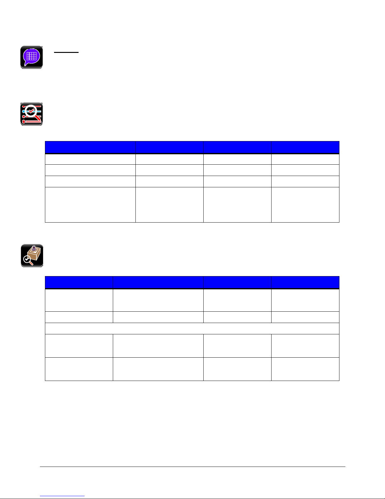
b. General
Select General to enable or disable the appropriate settings:
• Page Format Shading - Used for d i ag no s i n g la bel forma t issu es , en ab ling this options puts
a shade over white areas of the image on a label.
Test Options
The Te st Options function of the Diagnostics menu allows the user to test the options currently installed
on the printer. Select Test Options and navigate through the tabbed interface to select the option to be
tested. The tabs are navigated using the next and previous arrows in the taskbar.
Test Options Values Ranges Default
Cycle Cutter
Test Present Sensor
Test Rewinder
Test Ribbon Assembly
Once the selections have been made, select the Start button to begin the test.
1 to 999 1
N/A
N/A
N/A
Test GPIO
The Test GPIO functio n allows the user to test a conne cte d ap plicat or.
Selections Values Ranges Default
Enable Wrap Around Enabled
Disabled
Pulse Width
I/O Configuration
Sig 1/2 Input
1 to 2000 1000
Disabled
Input
Output
Sig 3/4 Input
Output
66
Input
Page 77

Selections Values Ranges Default
Sig 5/6 Input
Output
Sig 7/8 Input
Output
Select Test Write Mode
Read Mode
Pulse Mode
Write Mode
Enter the appropriate settings and select the green Start button.
Write Mode Values Ra nges Default
Sig 1 N/A
Sig 2 N/A
Sig 3 N/A
Sig 4 N/A
Sig 5 0
Output
Output
Write Mode
1
1
1
1
Sig 6 0
1
Sig 7 0
1
Sig 8 0
1
Read Mode
Enter the appropriate settings and select the green Start button.
Read Mode Values Ranges Default
Sig 1 0
1
Sig 2 0
1
1
1
1
1
1
67
Page 78

Read Mode Values Ranges Default
Sig 3 0
1
Sig 4 0
1
Sig 5 N/A
Sig 6 N/A
Sig 7 N/A
Sig 8 N/A
1
1
68
Page 79

Pulse Mode
Enter the appropriate settings and select the green Start button.
Read Mode Values Ranges Default
Sig 1 N/A
Sig 2 N/A
Sig 3 N/A
Sig 4 N/A
Sig 5 0
Sig 6 0
Sig 7 0
Sig 8 0
1
1
1
1
1
1
1
1
69
Page 80

70
Page 81

Operating, Adjusting and
5
Maintaining the Printer
5.1 Printhead Assembly Adjustments
Printhead Assembly Adjustments permit the mechanical compensation sometimes needed to
maintain print quality across the wide range of media types and sizes. Th e applicability and
adjustment methods for the printhead are described below.
5.1.1 Leveling Cam Adjustment
Whenever using narrow media (sizes that are less than the width of the printhead), adjust
the Leveling Cam for even pressure distribution.
If changing media sizes, readjust the Leveling Cam.
71
Page 82

Adjust the Printhead Leveling Cam as follows:
A. With media loaded, download your label format (or use a Test Label format) then
begin printing a small batch of labels.
B. While observing the printed output, rotate the Leveling Cam counter-clockwise until
the image fades across the label, as shown in Example 1 (below).
C. While observing the printed output, rotate the Leveling Cam clockwise until the
image is complete, with even contrast, as shown in Example 2 (below).
Example 1 – Too much adjustment
Under-adjustment of the Leveling Cam can cause problems that include ribbon
wrinkling, label tracking, and excessive platen and printhead wear.
Example 2 –
Correct adjustment
72
Page 83

5.1.2 Printhead Pressure Adjustment
Printhead Pressure Adjustment should only be performed after attempting to improve print
quality through the use of other prin t quality controls.
A. With media loaded, download your label format (or use a Test Label format) then
begin printing a small batch of labels.
B. While observing the printed output, turn each Pressure Adjustment Screw (use a
small coin or screwdriver) by the same amount until the image is complete, with
even contrast:
• Counterclockwise (+) to increase applied pressure, or;
• Clockwise (-) to decrease applied pressure.
Ensure that each arrow points in the same direction.
73
Page 84

5.2 Maintenance
This section details the recommended maintenance supplies, schedules, and methods.
Supplies
These items will help to safely and effectively clean the printer:
• Isopropyl alcohol • Soapy water/mild detergent
• Cotton swabs • Compressed air
• Clean, lint-free cloth • Printhead Cleaning Cards or Printhead Cleaning Film
• Lens tissue • Vacuum Cleaner
• Soft-bristle brush
Schedule
The following table details the recommended cleaning schedules:
Recommended Cleaning Schedule*
Component / Area Cleaning Interval** Supplies / Method
Mild detergent applied
with a dampened cloth;
see Section 5.2.7.
Vacuum; see Section
5.2.2.
Compressed air or a soft
brush; see Section 5.2.3.
Exterior Surfaces
Fan Filter
Interior Compartment
As needed, based on a weekly visual
inspection.
As needed, based on a weekly visual
inspection.
As needed, based on a weekly visual
inspection.
Compressed air, soft
Media Sensing
Components
As needed, based on a weekly visual
inspection.
brush, lens tissue and /
or isopropyl alcohol; see
Section 5.2.4.
Cotton swab or a cloth
Platen and Assist
Rollers
After each roll of media or ribbon;
sooner if needed.
dampened with isopropyl
alcohol; see Section
5.2.5.
Varies according to the media type:
Printhead
• Thermal transfer media – after
each roll of ribbon.
• Direct thermal media – after
Isopropyl alcohol, and if
necessary Cleaning Cards
or Cleaning Film; see
Section 5.2.1.
each roll of media, or as needed.
Ribbon Path
Components
(equipped models only)
*For optional equipment, refer to the documentation that accompanied the item(s).
**Whichever interval comes first.
As needed, based on a weekly visual
inspection.
74
Cotton swab or a cloth
dampened with isopropyl
alcohol; see Section
5.2.6.
Page 85

5.2.1 Cleaning the Printhead
Never use a sharp, hard or abrasive object on the printhead.
If print quality declines (symptoms can include unreadable bar codes or streaks through
text and graphics), the typical cause is debris buildup on the printhead which, left
unattended, can lead to premature dot failure. Depending upon the supplies and printing
parameters used, different cleaning methods are recommended.
Streaks can indicate a dirty or faulty printhead.
Proper cleaning is critical. To maintain peak
performance of the printer, Datamax-O’Neil offers a
complete line of cleaning products including pens,
cards, films and swabs. Visit our website at
http://www.datamax-oneil.com to learn more.
Certified Datamax-O’Neil – The worry free choice
for optimal printer performance.
Cotton Swab Procedure (for users of direct thermal media, or thermal transfer media
with wax ribbon):
A. Turn OFF the Power Switch and unplug the printer. Raise the cover, then raise the
Printhead Assembly and wait briefly for the printhead to cool.
B. Remove media and ribbon. Using a Cotton Swab moistened (not soaked) with
isopropyl alcohol, thoroughly clean the printhead.
75
Page 86

C. Allow the printhead to dry. Reinstall media (and ribbon, if needed). Plug in the
printer and turn ON the Power Switch. Run a few sample labels and examine them. If
streaking is still present, use Cleaning Card Procedure, below; otherwise, this
completes cleaning.
Cleaning Card Procedure
with wax/resin ribbon combinations; also for unsuccessful Cotton Swab cleaning attempts):
A. Raise the cover, then raise the Printhead Assembly and wait briefly for the
printhead to cool.
B. Remove media and ribbon then place a Cleaning Card under the printhead. (Part
number 70-2013-01 for 4-inch cards; and, 70-2014-01 for 6-inch cards)
C. Close and lock the Printhead Latch and disengage the Leveling Cam.
D. Close the cover then navigate to Menu>Tools>Maintenance>Cleaning. Then select
“Clean Now”.
E. After the cleaning card has been run through the printer, reinstall media (and ribbon,
if needed). Plug in and turn ON the printer. Run a few sample labels and examine
them. If streaking is still present, use the Cleaning Film Procedure, below; otherwise,
this completes cleaning.
(for users of direct thermal media, or thermal transfer media
Cleaning Film Procedure
printing with a Heat Value of 22 or higher, or when other methods prove unsuccessful):
A. Raise the cover, then raise the Printhead Assembly and wait briefly for the
printhead to cool.
B. Remove media and ribbon then place a sheet of Cleaning Film under the printhead.
(Part number 70-2087-01 for 4-inch film; 70-2087-02 for 6-inch film; and, 70-2087-
03 for 8-inch film)
C. Close and lock the Printhead Latch and disengage the Leveling Cam.
D. Close the cover then navigate to Menu>Tools>Maintenance>Cleaning. Then select
“Clean Now”.
E. After the cleaning film has been run through the printer, turn OFF the Power Switch
and unplug the printer. Open the cover then raise the Printhead Assembly and wait
briefly for the printhead to cool. Using a cotton swab moistened (not soaked)
with isopropyl alcohol, clean the printhead then allow it to dry.
F. Reinstall media (and ribbon, if needed). Plug in and turn ON the printer. Run a few
sample labels and examine them. If streaking is still present the printhead may need
to be replaced; see Section 5.3.
(for users of thermal transfer media and resin ribbon, when
76
Page 87

5.2.2 Cleaning the Fan Filter
On equipped models, a Fan Filter keeps dust and debris from entering the printer. To assure
continued airflow through the printer, clean the Fan Filter as follows:
A. Turn OFF the Power Switch and unplug the power cord from the AC Receptacle.
B. Using a vacuum, clean the Fan Filter.
5.2.3 Cleaning the Interior Compartment
Inside the printer, paper dust from the media can accumulate to produce small voids in the
print. To assure continued void free printing, clean the Interior Compartment as follows:
A. Turn OFF the Power Switch and unplug the power cord from the AC Receptacle.
B. Raise the Cover then remove media and ribbon.
C. Remove all media and ribbon.
D. Using compressed air (or a soft brush), clean all debris from Interior Compartment.
77
Page 88

5.2.4 Cleaning the Media Sensing Components
Paper dust and adhesive from the media can accumulate on the sensing components and
produce TOF problems. To avoid problems, clean the Media Sensor and Light Bar as follows:
A. Turn OFF the Power Switch and unplug the power cord from the AC Receptacle.
B. Unlock the Prin thead Latch, raise the Printhead Assembly, and remove media.
C. Using compressed air, clean all debris from the Media Sensor and the Light Bar. (In
cases of extreme buildup, a Cotton Swab or lens tissue dampened with isopropyl
alcohol can be used.)
5.2.5 Cleaning the Platen and Assist Rollers
Rollers contaminated with grit, label adhesive, or ink can lead to a decline in print quality
and, in extreme cases, cause labels to adhere and wrap the roller. Clean the Platen and
Assist Rollers as follows:
78
Page 89

A. Turn OFF the Power Switch and unplug the power cord from the AC Receptacle.
B. Raise the Cover then remove the Door and tearbar. Unlock the Printhead Latch and
raise the Printhead Assembly.
C. Remove media and ribbon.
D. Using a Cotton Swab (or lint-free cloth) dampened with isopropyl alcohol, wipe the
Platen and the Assist Roller clean. Manually rotate the rollers as necessary, wiping,
rotating, and repeating until the surfaces of each are clean.
5.2.6 Cleaning the Ribbon Path Components (Thermal Transfer equipped)
Smooth ribbon flow can become impeded if the components are dirty. Clean them as follows:
A. Turn OFF the Power Switch and unplug the power cord from the AC Receptacle. Raise
the Cover then remove media and ribbon.
B. Using a Cotton Swab dampened with alcohol, wipe the Ribbon Idlers clean.
79
Page 90

C. Using a Cotton Swab dampened with alcohol, wipe the Ribbon Shield clean.
D. Reload media and ribbon then close the Cover.
80
Page 91

5.2.7 Cleaning the Exterior Surfaces
When soiled, the exterior surfaces of the printer should be cleaned using a general-purpose
cleanser. Never use abrasive cleansers or solvents, and never pour a cleanser directly onto
the printer.
A. Turn OFF the Power Switch and unplug the power cord from the AC Receptacle.
B. Using a soft cloth (or sponge) dampened with a non-abrasive cleanser, wipe the
exterior surfaces clean.
C. Allow the surfaces to dry before reconnecting power.
81
Page 92
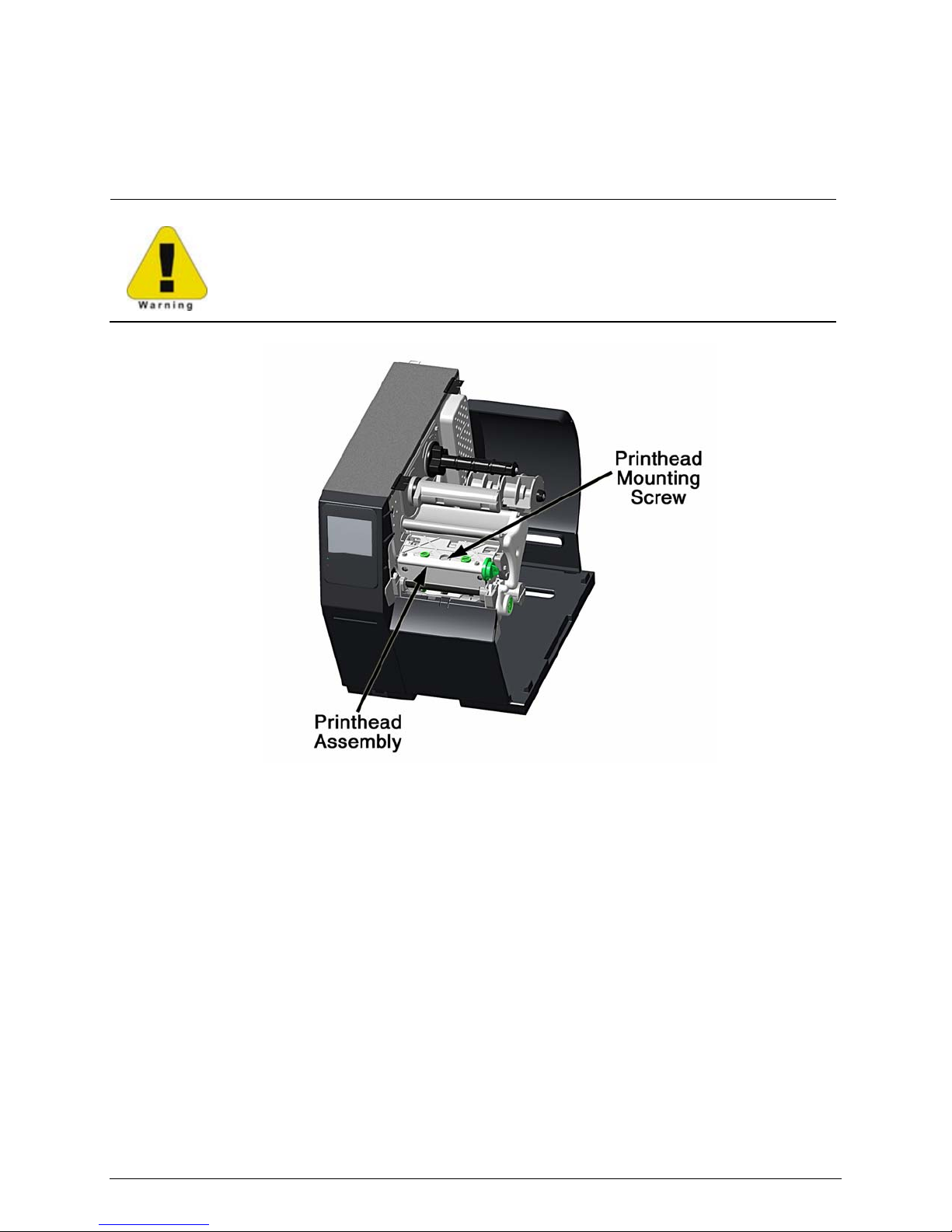
5.3 Replacing the Printhead
If the printhead needs to be replaced, follow the procedure below:
• Only use a Datamax-O’Neil IntelliSEAQ™ printhead.
• Printheads are fragile; handle with extreme care and never use sharp
objects on the surface.
• If you have questions, contact a qualified technician or Datamax-O’Neil
Technical Support before proceeding.
A. Turn OFF the Power Switch then touch a bare metal printer surface (e.g., the frame)
to discharge any static electricity present on your body.
B. Unplug the printer and open the access cover. If ribbon is installed, remove it .
C. Lower the Printhead Assembly and loosen the Printhead Mounting Screw. (If using an
H-8308X model, loosen both mounting screws.)
D. Carefully raise the Printhead Assembly. Grasp the printhead then disconnect the two
cables and remove the printhead.
E. Position a new printhead under the Printhead Assembly and connect the previously
removed cables.
F. After ensuring that the printhead cables are not pinched, place the printhead onto
the locating pins under the Printhead Assembly and secure it by tightening the
Printhead Mounting Screw(s). [Do not over-tighten the screw(s)].
82
Page 93

G. Using a Cotton Swab moistened (not soaked) with isopropyl alcohol, clean the
printhead then allow it to dry.
H. If removed, reinstall ribbon. Lower and lock the Printhead Assembly. Plug in the
printer and turn ON the Power Switch.
83
Page 94

84
Page 95

6 Troubleshooting
6.1 Problem Resolution
The following chart provides basic troubleshooting steps for diagnosing problems with the
printer. If the symptoms remain after troubleshooting, contact your technical support
representative.
Warning: Do not open the right side panel that covers the internal electronic components.
Due to the high voltage and the sensitivity of the components, opening the panel can lead
to injury and may void the manufacturer’s warranty.
Symptom Causes Solutions
Redesign the label using another
method
System Error
Out of Ribbon
Out of Paper
Cutter Jammed
Rewinder Full
Printhead Unlatched
Print media settings may not match the
installed media and ribbon.
The ribbon diameter may be too low to
continue printing.
A fault may have occurred with the ribbon
controller hardware or software.
The printer may be out of media. Install a new media roll.
The media guides may not be adjusted
correctly.
The media is too transparent to be
detected.
The cutter may have a jam.
Cutter Home sensor may be dirty.
Cutter hardware has failed.
The rewinder may be full.
The rewinder may be obstructed and turning
slowly.
The printhead may be unlatched.
The printhead latch sensor may be faulty.
Use a different communications
channel.
Contact your Technical Support
representative.
Install a new ribbon
Ensure the latest software has been
installed.
Correct the media guide set-
Perform “Calibrate Sensors.”
Perform “Calibrate Sensors.”
Remove the jam from the cutter.
Test the cutter.
Clean the Cutter Home sensor.
Test the cutter.
Ensure the cutter is properly
installed.
Test the cutter.
Remove the media from the
rewinder.
Test the rewinder function.
Check for obstructions that hinder the
rewinder from turning.
Test the rewinder function.
Close and latch the printhead
mechanism.
Contact your technical support
representative.
tings.
85
Page 96

Symptom Causes Solutions
Printhead Hot
FPGA Hardware
NV RAM Hardware
PAPER Sensor Blocked
Paper Calibration
No Top-of-Form Found
GPIO Hardware
Present Sensor
Hardware
The printhead too hot or is faulty.
There may be a poor cable connection.
The main controller board may be
The main controller board may be
faulty.
faulty.
Allow to cool or contact your technical
support representative.
Contact your technical support
representative.
Ensure the latest software update has
been performed.
Contact your technical support
representative.
Clean the debris from the sensor.
Adhesive, dirt or remnants of a label may
be covering the sensor.
Perform “Calibrate Sensors”
calibration.
The main controller board may be faulty.
The Top-of-Form sensor failed the
“Calibrate Sensors” calibration due to a
faulty sensor.
The wrong Top-of-Form sensor side may
have been selected and not able
to read
media characteristics.
The characteristics of the media may not
be sensed by the printer. (Ex. gap,
notch,
mark)
The gap or mark was not found.
Contact your technical support
representative.
Contact your technical support
representative.
Ensure the Top-of-Form has
correctly.
Set the paper mode to continuous.
Install different media.
Ensure the Top-of-Form has
set correctly.
been set
been
Install different media.
Check the print mechanism for a
The label image size exceeded the
maximum of 99 inches.
jam.
Calibrate the printer for the
media
being used.
Clean the debris from the sensors.
There may be dirt or debris obstructing the
Top-of-Form sensor.
Perform “Calibrate Sensors”
calibration.
There may be a poor connection to the
GPIO logic board.
The GPIO logic board may be faulty.
Contact your technical support
representative.
Contact your technical support
representative.
There may be a poor connection. Perform the Present Sensor test.
The Present Sensor module may be
faulty.
The Ribbon Version may need to be
upgraded.
There may be a poor connection.
Perform the Present Sensor test.
Ensure the latest software has been
installed.
Contact your technical support
representative.
paper
The Ribbon Controller module may be
faulty.
Contact your technical support
representative.
86
Page 97

6.2 Troubleshooting Print Quality
Tools
Datamax-O’Neil approved media
Datamax-O’Neil approved matching ribbon (for printers with the thermal transfer
option)
3mm hex head wrench
1.5mm hex head wrench
Magnifying lens
Barcode verifier and grading system
Printhead cleaning card
Printhead cleaning pen
Preliminary Instructions
1. Ensure the latest software has been loaded.
2. Load the media and ribb on according to the instruction s in the Setup section.
Note: Verify that the ribbon is tightly wound on the supp ly roll with no wrink les .
Note: Verify that t he paper is pr operly exiting the printer.
3. Specify the appropriate media and ribbon in the menu.
4. Print a Quality Label from the Test menu.
5. Examine the print quality.
Note: Some imperfec tions can be caused by a contaminated printhead. Clean the pri n thead and
reprint the label.
Symptom Possible Solutions
No Print or Poor Print Quality
Light Print on One Side
Print Quality Defect
Verify the proper media and ribbon are being used.
Verify the printhead connections are fully seated.
Adjust the ribbon cam and ribbon shield to add tension to the
print side.
Verify the printhead connections are fully seated.
printhead.
Contact your technical support representative.
Clean the printhead and platen roller with factory-approved
supplies.
Verify there are no ribbon folds or wrinkles under the printhead.
Replace the
cleaning
light
Print Quality gets worse over time
Replace the printhead if there is a missing dot.
Printhead is at the end of life and should be replaced.
Contact your technical support representative.
87
Page 98

Symptom Possible Solutions
Incomplete horizontal lines requires an increase in the
setting and/or more tension applied to the lighter print side of the
ribbon shield.
sharpness
Diminished print quality on the Quality
Label
Ladder barcode quality is diminished
Image size is out of the print area (off the
side or top or truncated from the
label
next
For higher-grade barcodes, lighten the print by reducing the
setting.
For white specks inside dark boxes, increase the darkness
and clean the printhead and platen roller.
If the small font is not readable, increase the darkness setting.
When dithering increments are not equal, adjust the darkness
If graphics are not displayed properly, adjust the sharpness setting.
Examine the media adjustment levers and ensure there is a
.8mm to 1.5mm gap between the levers and the media.
Turn off print truncation.
Ensure the image width is the same as the print width.
darkness
setting
setting.
6.3. Error and Warning Messages
The printer displays messages when the possibility of a problem or an actual fault occurs.
Depending upon the displayed message, find the possible action or solution in the tables
below.
Error Messages
The following messages may be displayed:
Errors Description
SYSTEM ERROR Illegal label format or communications error
OUT OF RIBBON Out of ribbon
OUT OF PAPER Out of paper
CUTTER JAMMED Cutter is jammed
REWINDER FULL Rewinder is full
PRINT HEAD UNLATCHED Printhead is unlatched
PRINTHEAD HOT Printhead is critically hot
FPGA HARDWARE Analog to digital converter hardware fault
NV RAM HARDWARE Non-volatile memory hardware fault
PAPER SENSOR BLOCKED Top-of-form sensor blocked or hardware fault
PAPER CALIBRATION Could not calibrate media
NO TOP OF FORM FOUND Could not find a gap or mark
RIBBON HARDWARE Ribbon controller hardware fault
PRESENT SENSOR Present Sensor hardware fault
GPIO HARDWARE GPIO hardware fault
MOTOR HOT Motor is critically hot
Note: System errors are not caused by media mismatches but can be caused by a poor label
format.
88
Page 99

Warning Messages
The following messages may be displayed:
Warnings Description
RIBBON LOW Ribbon level low
MAINTENANCE REMINDER Maintenance timer has expired
POWER SUPPLY HARDWARE Printhead voltage above maximum specifications
POWER SUPPLY LOW Printhead voltage below minimum specifications
UNRECOGNIZED PRINTHEAD Unidentified printhead installed
PRINTHEAD COOLING Printhead is cooling down
PAPER CALIBRATION MARGINAL Paper sensor calibration marginal
PERFORM CALIBRATE SENSORS There is a need to run Calibrate Sensors
UNLATCH THE PRINTHEAD Printhead needs to be unlatched
LOAD PAPER No paper while idle
LATCH THE PRINTHEAD Printhead unlatched while in idle
PAPER LOW The paper media is low
CUTTER NOT INSTALLED The cutter is enabled but not installed
GPIO NOT INSTALLED The GPIO is enabled but not installed
PRESENT SENSOR NOT INSTALLED The present sensor is enabled but not installed
RIBBON NOT INSTALLED The ribbon controller is enabled but not installed
REWINDER NOT INSTALLED The rewinder is enabled but not installed
CLOSE THE CUTTER COVER The cutter cover is not magnetically closed
MODEL MISMATCH The printer has received settings intended for a different printer model
PAPER WIDTH HARDWARE The paper width sensor is malfunctioning
89
Page 100

90
 Loading...