

Page 1
DLR-DK001-XX Family
RFID UHF Desktop Reader EU/US
Product Reference Guide
Page 2

Datalogic S.r.l.
Via S. Vitalino, 13
40012 Calderara di Reno
Italy
Tel. +39 051 3147011
Fax +39 051 3147205
©2017 Datalogic S.p.A. and/or its affiliates
An Unpublished Work - All rights reserved. No part of the
contents of this documentation or the procedures described
therein may be reproduced or transmitted in any form or by
any means without prior written permission of Datalogic
S.p.A. and/or its affiliates. Owners of Datalogic products are
hereby granted a non-exclusive, revocable license to
reproduce and transmit this documentation for the
purchaser's own internal business purposes. Purchaser shall
not remove or alter any proprietary notices, including
copyright notices, contained in this documentation and shall
ensure that all notices appear on any reproductions of the
documentation. Should future revisions of this manual be
published, you can acquire printed versions by contacting your
Datalogic representative.
Electronic versions may either be downloadable from the
Datalogic website (www.datalogic.com) or provided on
appropriate media. If you visit our website and would like to
make comments or suggestions about this or other Datalogic
publications, please let us know via the "Contact Datalogic"
page.
Disclaimer
Datalogic has taken reasonable measures to provide
information in this manual that is complete and accurate,
however, Datalogic reserves the right to change any
specification at any time without prior notice.
Datalogic and the Datalogic logo are registered trademarks of
Datalogic S.p.A. in many countries, including the U.S.A. and
the E.U. DLR-DK001 is a trademark of Datalogic S.p.A. and/or
its affiliates. All other trademarks and brands are property of
their respective owners.
.
Page 3

Product Reference Guide i
Table of Contents
Description ....................................................................................... 1
Models P/N ..................................................................................... 1
General Features ............................................................................. 2
Using the DLR-DK001-XX ..............................................................2
The DLR-DK001-XX Top Panel ...................................................... 3
Acoustic ............................................................................................ 3
Accessories ...................................................................................... 3
Technical Specifications ........................................................4
Reader-Tag Link Profiles ................................................................ 5
Radiation Patterns ..........................................................................6
Getting Started ................................................................................ 7
Driver Installation for Serial Port Emulator ........................7
Connecting to the DLR-DK001-XX .....................................10
Firmware Upgrade ...............................................................10
Mechanical Specification ..............................................................11
Datalogic Limited Factory Warranty ...........................................12
Services and Support ....................................................................15
Page 4

ii DLR-DK001-xx
NOTES
Page 5
Product Reference Guide 1
RFID Reader DLR-DK001-XX
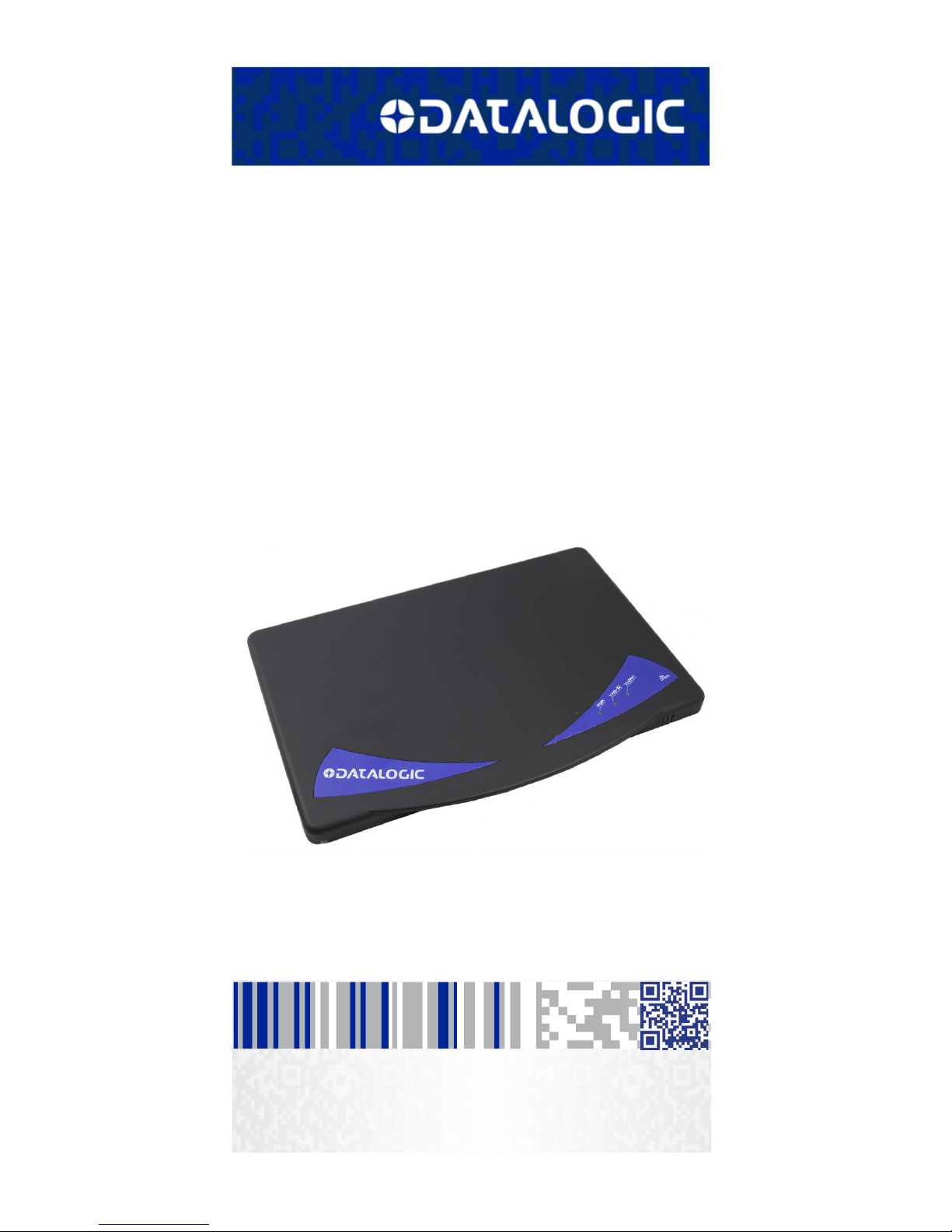
Description
The DLR-DK001-XX is a multipurpose desktop UHF RFID
reader. It is offered in two different models to fit the
different frequency standards in the EU and US regions.
It is compliant with UHF RFID ISO 18000-63 and EPC Class
1 Gen 2 standards. The Reference Document is:
“EPC Radio-Frequency Identity Protocols Class-1
Generation-2 UHF RFID”, Protocol for Communications at
860 MHz – 960 MHz, Version 2.0.1 (April 23, 2015).
The DLR-DK001-XX has an integrated antenna suited for
short to medium range applications. This reader is
powered and controlled by a USB cable that allows it to
read EPC codes tags in an easy desktop environment.
Thanks to its low profile and size, the DLR-DK001-XX
reader is the right choice for various applications such as
point-of-sales, document tracking, RFID Tag programming
and control stations.
It can be used as a building block for smart shelves and
displays. The two versions are covering most of the RFID
needs worldwide (retailers, forwarders, warehouses, etc).
Models P/N
Model P/N RF carrier frequency range
DLR-DK001-EU 865.6 ÷ 867.6 MHz
DLR-DK001-US 902.0 ÷ 928.0 MHz
Page 6
General Features
2DLR-DK001-xx
General Features
The DLR-DK001-XX is mainly dedicated to fixed Desktop
setups, but a fixed wall-mount point-of-access is possible
as well. The Desktop configuration allows it to interact
directly with legacy application, office automation SW and
many other generic service and maintenance applications.
The integrated circular antenna makes the radiation
pattern a good compromise in terms of directivity. This
means practically no orientation problems will be
experienced for a population of UHF Tags being located in
its proximity.
Special attention has been given to minimizing the mean
current consumption by limiting the active read time.
The USB 2.0 is seen as a serial Virtual Com Port (VCP). All
machines with Windows OS versions, Linux vers. 2.40 and
greater, having proper VCP drivers could be interfaced. The
port is used for powering, too, so it must be connected to
500 mA rated USB Ports.
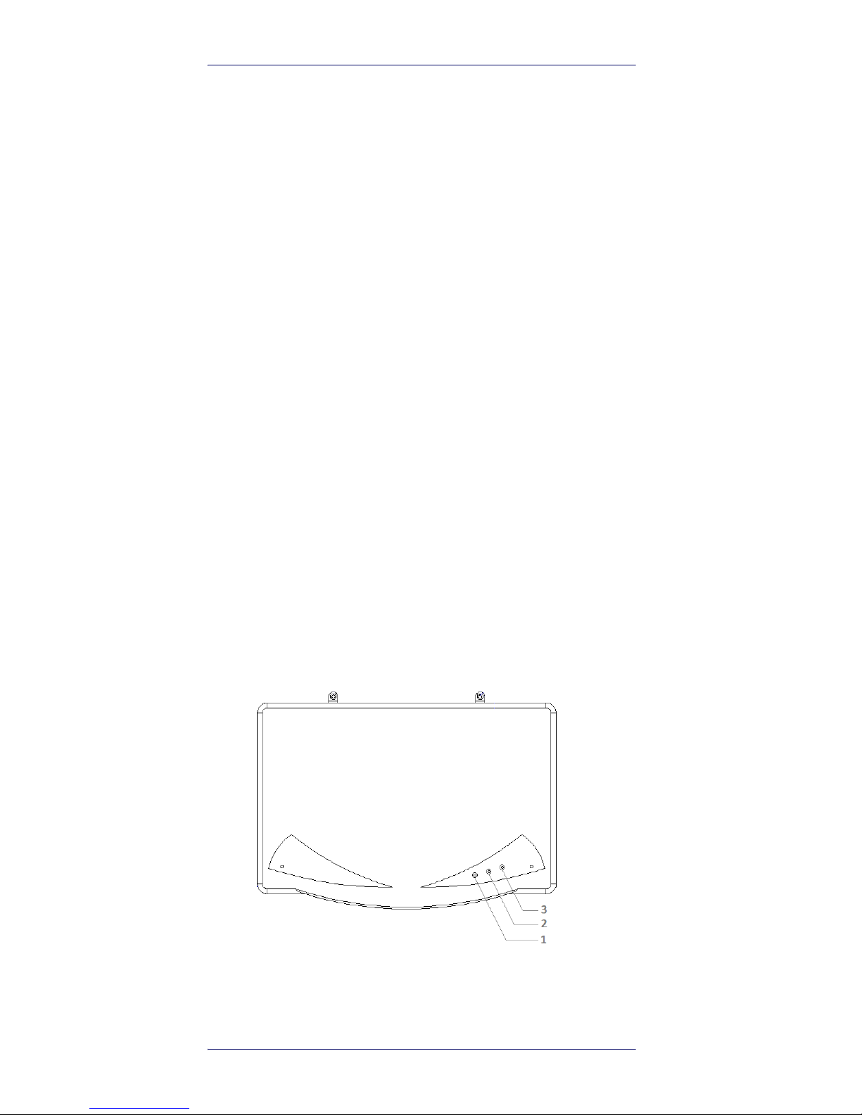
Using the DLR-DK001-XX
The DLR-DK001-XX normal behavior is to capture all the
sensed identification codes associated to the reachable
UHF Tags. The reader’s Top Panel is the User Interface. All
the commands are issued from the host’s application.
Figure 1. DLR-DK001-XX Top Panel
Page 7

The DLR-DK001-XX Top Panel
Product Reference Guide 3
The DLR-DK001-XX Top Panel
With reference to the Fig. 1 above, here is a Table with the
three main elements of the User Interface located on the
Top Panel:
Table 1- DLR-DK001 Top Panel LEDs
Acoustic
For events signaling, one more resource exists to
complete the User Interface: a buzzer than can be
programmed by the host application as a local user alarm.
Accessories
A standard Type A connector cable comes with the
product.
A kit of accessories for an easy mounting to wall or desk is
supplied (screws, rubber-feets, wall-hooks, rawl plugs,
etc).
Figure 2. DLR-DK001-XX Wall Mount Accessories
N° Name Description
1 POWER Power ON - Green LED
2 TAG-ID Tag Detection - Red Blinking LED
3 TX/RX USB Communication Activity - Yellow Blinking LED
Disposal of the product
Do not dispose the product in municipal or
household waste. Please check your local
regulations for recycle & disposal of electronic
products.
Page 8

Accessories
4DLR-DK001-xx
Technical Specifications
Item Description
Physical Characteristics
Reader Dimension
(WLH) 29.7 x 20.5 x 1.5 cm3 / 11.7 x 8.1 x
0.6 in
3
Length of USB
1.5 m / 4.9 ft
Weight
525 g / 18.42 oz
Electrical Characteristics
Electrical Power
max 400 mA - 5 V dc bus powered (USB)
Reader - Tag Link
Type
UHF - RFID
Standard
ISO 18000-63/EPC C1G2
Frequency Bands
865.60 ÷ 867.60 MHz European standard
902.00
÷
928.00 MHz US standard
RF Power
Programmable in 18 levels from 5dBm
e.r.p. (3mW e.r.p.) to 22dBm e.r.p.
(150mW e.r.p.)
Antenna
Integrated circular polarized (horizontal)
Number of Channels
4 channels compliant to European
Standard
50 hopping channels compliant to US
standard
Reading Range
Up to 90cm
Reader - Host Link
USB type
USB 2.0 Full Speed (12 Mbit/s) Type A
dev. port
Virtual COM Port
Baudrate: 115.200 kbps
Databits: 8; Stopbits: 1;
Parity: none; Flow control: none
User Environment
Partic. & Water
IP40
Operating
0°C to 50°C / 32°F to 122°F
Storage
-20°C to 60°C / -4°F to 140°F
ESD
Air ± 16kV
Contact ± 8kV
Page 9

Reader-Tag Link Profiles
Product Reference Guide 5
Reader-Tag Link Profiles
The DLR-DK001-XX readers support different
modulations and RF return link profiles according to EPC
Class1 Gen2 protocols.
Main profiles have been tested for the compliance with
ETSI and FCC regulations.
Table 2- DLR-DK001-XX Reader to tag link profiles
Link
Profile
Regulation Modulation Return Link
0 ETSI - FCC DSB-ASK; f=40KHz FM0; f=40KHz
1 ETSI - FCC DSB-ASK; f=40KHz Miller (M=4); f=256 KHz
Page 10

Radiation Patterns
6DLR-DK001-xx
Radiation Patterns
Both the DLR_DK001-XX products, due to their internally
placed antenna, have a non-ideal radiation pattern. Here
below are reported their radiation patterns.
Figure 3. DLR-DK001 Radiation pattern H plane
Figure 4. DLR-DK001 Radiation pattern V plane
Page 11

Getting Started
Product Reference Guide 7
Getting Started
The reader can be connected to all the hosts with 500 mA
rated USB ports and recognized as a serial Virtual COM
Port: Win-PC, Linux-PC, etc.
Please, first verify to have installed framework 2.0 or
higher in your PC.NET before proceeding.
Driver Installation for Serial Port
Emulator
VCP drivers for your operating system can be downloaded
from the Products section of the Datalogic website. Get
the last version driver.
The following is a sample procedure for Windows-based
systems:I
1. Connect the reader to the USB port of your PC.
2. If the driver is not yet installed, the Found New HW
Wizard pop-up window is displayed.
3. The Wizard will guide you step by step to get the
driver or its link and to run its installation.
4. Once the installation is completed, the wizard will
inform you that your USB Serial Port is ready.
Page 12

Getting Started
8DLR-DK001-xx
5. Click Finish to complete the procedure.
6. Check the COM X name assumed by the USB serial
port. Follow the Control Panel > System > Hardware >
Device Manager > Ports > USB Serial Port (COM X)
path.
Page 13

Getting Started
Product Reference Guide 9
7. In our example below the USB Serial Port is named as
COM 4.
Page 14

Getting Started
10 DLR-DK001-xx
Connecting to the DLR-DK001-XX
From the Products section of the Datalogic website you
can download the DL RFID Software Tool Controller for
Windows file.
After its installation, you will get its icon on the PC
desktop. Click the icon to launch it:
•Click on File > Connect to select the RS232
Connection Type and to associate the COM X port.
Click connect to complete your action.
• Place a Tag on the reader; click Start Inventory to see
the tag’s EPC code displayed on the main window.
For more details on the demo DL RFID Software Tool
Controller for Windows application and its additional
features, refer to the dedicated manual, downloadable
from the Products section of the Datalogic website.
Firmware Upgrade
The Firmware Upgrade tool is available for free download
at the RFID Products SW/FW section of the Datalogic
website.
To upgrade the firmware, follow the steps below:
1. Connect the reader to the USB port of your PC.
2. Verify the correct COM port associated to the reader.
3. Run the FW upgrade program.
4. Click Open to select the COM port and the image (bin)
file.
5. Click Upgrade.
6. Once the upgrade is completed, disconnect and
reconnect the USB cable for a power-on reset. At the
power-up, the new FW will be operative in the reader.
Page 15

Mechanical Specification
Product Reference Guide 11
Mechanical Specification
Here below is the drawing of the DLR-DK001 reader.
The optional hanging tools for wall-mounting could be
found in the associated kit.
Figure 5. DLR-DK001-XX Mechanical & Dimensions
Page 16

Datalogic Limited Factory Warranty
12 DLR-DK001-xx
Datalogic Limited Factory Warranty
Warranty Coverage
Datalogic warrants to Customer that Datalogic's products will be
free from defects in materials and workmanship for a period of
one year from product shipment. Datalogic hardware products
are warranted against defects in material and workmanship
under normal and proper use. The liability of Datalogic under this
warranty is limited to furnishing the labor and parts necessary to
remedy any defect covered by this warranty and restore the
product to its normal operating condition. Repair or replacement
of product during the warranty does not extend the original
warranty term. Products are sold on the basis of specifications
applicable at the time of manufacture and Datalogic has no
obligation to modify or update products once sold.
If Datalogic determines that a product has defects in material or
workmanship, Datalogic shall, at its sole option repair or replace
the product without additional charge for parts and labor, or
credit or refund the defective products duly returned to Datalogic.
To perform repairs, Datalogic may use new or reconditioned parts,
components, subassemblies or products that have been tested
as meeting applicable specifications for equivalent new material
and products. Customer will allow Datalogic to scrap all parts
removed from the repaired product. The warranty period shall
extend from the date of shipment from Datalogic for the duration
published by Datalogic for the product at the time of purchase
(Warranty period). Datalogic warrants repaired hardware devices
against defects in workmanship and materials on the repaired
assembly for a 90 day period starting from the date of shipment
of the repaired product from Datalogic or until the expiration of
the original warranty period, whichever is longer. Datalogic does
not guarantee, and it is not responsible for, the maintenance of,
damage to, or loss of configurations, data, and applications on the
repaired units and at its sole discretion can return the units in the
“factory default” configuration or with any software or firmware
update available at the time of the repair (other than the
firmware or software installed during the manufacture of the
product). Customer accepts responsibility to maintain a back up
copy of its software and data.
Warranty Claims Process
In order to obtain service under the Factory Warranty, Customer
must notify Datalogic of the claimed defect before the expiration
of the applicable Warranty period and obtain from Datalogic a
return authorization number (RMA) for return of the product to a
designated Datalogic service center. If Datalogic determines
Customer’s claim is valid, Datalogic will repair or replace product
without additional charge for parts and labor. Customer shall be
responsible for packaging and shipping the product to the
designated Datalogic service center, with shipping charges
prepaid. Datalogic shall pay for the return of the product to
Customer if the shipment is to a location within the country in
which the Datalogic service center is located. Customer shall be
responsible for paying all shipping charges, duties, taxes, and any
Page 17

Datalogic Limited Factory Warranty
Product Reference Guide 13
other charges for products returned to any other locations.
Failure to follow the applicable RMA policy, may result in a
processing fee. Customer shall be responsible for return
shipment expenses for products which Datalogic, at its sole
discretion, determines are not defective or eligible for warranty
repair.
Warranty Exclusions
The Datalogic Factory Warranty shall not apply to:
(i) any product which has been damaged, modified, altered,
repaired or upgraded by other than Datalogic service personnel or its authorized representatives;
(ii) any claimed defect, failure or damage which Datalogic
determines was caused by faulty operations, improper
use, abuse, misuse, wear and tear, negligence, improper
storage or use of parts or accessories not approved or
supplied by Datalogic;
(iii) any claimed defect or damage caused by the use of prod-
uct with any other instrument, equipment or apparatus;
(iv) any claimed defect or damage caused by the failure to
provide proper maintenance, including but not limited to
cleaning the upper window in accordance with product
manual;
(v) any defect or damage caused by natural or man-made
disaster such as but not limited to fire, water damage,
floods, other natural disasters, vandalism or abusive
events that would cause internal and external component damage or destruction of the whole unit, consumable items;
(vi) any damage or malfunctioning caused by non-restoring
action as for example firmware or software upgrades,
software or hardware reconfigurations etc.;
(vii) the replacement of upper window/cartridge due to
scratching, stains or other degradation and/or
(viii) any consumable or equivalent (e.g., cables, power supply,
batteries, keypads, touch screen, triggers etc.).
No Assignment
Customer may not assign or otherwise transfer its rights or
obligations under this warranty except to a purchaser or
transferee of product. No attempted assignment or transfer in
violation of this provision shall be valid or binding upon Datalogic.
DATALOGIC'S LIMITED WARRANTY IS IN LIEU OF ALL OTHER
WARRANTIES, EXPRESS OR IMPLIED, ORAL OR WRITTEN,
STATUTORY OR OTHERWISE, INCLUDING, WITHOUT LIMITATION,
ANY IMPLIED WARRANTIES OF MERCHANTABILITY, FITNESS FOR
A PARTICULAR PURPOSE, OR NONINFRINGEMENT. DATALOGIC
SHALL NOT BE LIABLE FOR ANY DAMAGES SUSTAINED BY
CUSTOMER ARISING FROM DELAYS IN THE REPLACEMENT OR
REPAIR OF PRODUCTS UNDER THE ABOVE. THE REMEDY SET
FORTH IN THIS WARRANTY STATEMENT IS THE CUSTOMER’S
SOLE AND EXCLUSIVE REMEDY FOR WARRANTY CLAIMS. UNDER
NO CIRCUMSTANCES WILL DATALOGIC BE LIABLE TO CUSTOMER
OR ANY THIRD PARTY FOR ANY LOST PROFITS, OR ANY
INCIDENTAL, CONSEQUENTIAL INDIRECT, SPECIAL OR
Page 18

Datalogic Limited Factory Warranty
14 DLR-DK001-xx
CONTINGENT DAMAGES REGARDLESS OF WHETHER DATALOGIC
HAD ADVANCE NOTICE OF THE POSSIBILITY OF SUCH DAMAGES.
Risk of Loss
Customer shall bear risk of loss or damage for product in transit
to Datalogic. Datalogic shall assume risk of loss or damage for
product in Datalogic’s possession. In the absence of specific
written instructions for the return of product to Customer,
Datalogic will select the carrier, but Datalogic shall not thereby
assume any liability in connection with the return shipment.
Page 19

Services and Support
Product Reference Guide 15
Services and Support
Datalogic provides several services as well as technical
support through its website. Log on to www.datalogic.
com and click on the links indicated for further
information.
Products
Search through the links to arrive at your product page
where you can download specific Manuals and Software &
Utilities
.
Service & Support
• Technical Support
- Product documentation and
programming guides and Technical Support Department
in the world
• Service Programs - Warranty Extensions and
Maintenance Agreements
• Repair Services - Flat Rate Repairs and Return Material
Authorization (RMA) Repairs
• Downloads – Manuals & Documentation, Data Sheets,
Product Catalogues, etc.
Contact Us
• Information Request Form and Sales & Service
Network
Page 20

©2017 Datalogic S.p.A. and/or its affiliates. All rights
reserved. Datalogic and the Datalogic logo are registered
trademarks of Datalogic S.p.A. in many countries, including
the U.S. and the E.U.
Datalogic S.r.l.
Via San Vitalino 13 | Calderara di Reno (BO) |40012 | Italy
Telephone: +39 051 3147011
|
Fax: +39 051 3147205
www.datalogic.com
820079314 (Rev A) March 2017
 Loading...