

Page 1
RIDA™ DBT6400
Product Reference Guide
Pocket Handheld Imager Scanner
with Bluetooth® Wireless Technology
Page 2

Datalogic USA Inc.
959 Terry Street
Eugene, OR 97402
U.S.A.
Telephone: (541) 683-5700
Fax: (541) 345-7140
©2016-2018 Datalogic S.p.A. and/or its affiliates
All rights reserved. Without limiting the rights under copyright, no part of this docu-
mentation may be reproduced, stored in or introduced into a retrieval system, or transmitted in any form or by any means, or for any purpose, without the express written
permission of Datalogic S.p.A. and/or its affiliates. Owners of Datalogic products are
hereby granted a non-exclusive, revocable license to reproduce and transmit this docu
mentation for the purchaser's own internal business purposes. Purchaser shall not
remove or alter any proprietary notices, including copyright notices, contained in this docu
mentation and shall ensure that all notices appear on any reproductions of the documentation. Should future revisions of this manual be published, you can acquire printed
versions by contacting your Datalogic representative. Electronic versions may either be
downloadable from the Datalogic website
(www.datalogic.com) or provided on appropriate
media. If you visit our website and would like to make comments or suggestions about
this or other Datalogic publications, please let us know via the "Contact Datalogic" page.
-
Disclaimer
Datalogic has taken reasonable measures to provide information in this manual that is
complete and accurate, however, Datalogic reserves the right to change any specification
at any time without prior notice.
Datalogic and the Datalogic logo are registered trademarks of Datalogic S.p.A. in many
countries, including the U.S. and the E.U.
RIDA and Datalogic Aladdin are trademarks of Datalogic S.p.A. and/or its affiliates.
The Bluetooth word mark and logos are owned by Bluetooth SIG, Inc. and any use of such
marks by Datalogic Group companies is under license. All other brand and product names
may be trademarks of their respective owners.
Patents
See www.patents.datalogic.com for patent list.
Page 3

Table of Contents
INTRODUCTION ....................................................................................................................................................... 1
About the Scanner .............................................................................................................................................................1
Using the RIDA DBT6400 ..........................................................................................................................................1
About this Manual .............................................................................................................................................................3
Overview ....................................................................................................................................................................3
Manual Conventions .................................................................................................................................................3
Technical Support ..............................................................................................................................................................4
Datalogic Website Support ......................................................................................................................................4
Reseller Technical Support ......................................................................................................................................4
Telephone Technical Support ..................................................................................................................................4
SETUP....................................................................................................................................................................... 5
Unpacking ...........................................................................................................................................................................5
Setting Up the Reader .......................................................................................................................................................5
Configuring the BC6020 Base Station ....................................................................................................................5
Using the BC6020 Base Station ..............................................................................................................................6
Charging the Batteries .............................................................................................................................................7
Replacing the Battery Pack ......................................................................................................................................8
Linking to a Host ................................................................................................................................................................9
Linking to a Base Station ............................................................................................................................................... 11
Base Station Interface Selection ................................................................................................................................... 12
Configuring the Interface ...................................................................................................................................... 12
Customizing Configuration Settings ............................................................................................................................ 13
Using the Programming barcodes ....................................................................................................................... 13
Interface Settings .................................................................................................................................................. 14
Configuring Other Features .................................................................................................................................. 14
Software Version Transmission ........................................................................................................................... 14
Compatibility ................................................................................................................................................................... 16
Supported BT Specification ................................................................................................................................... 16
Device and operative system supported ............................................................................................................. 16
Tested Devices ....................................................................................................................................................... 17
Cleaning Procedure ......................................................................................................................................................... 18
Cleaning plastic surfaces ...................................................................................................................................... 18
Cleaning electrical contact surfaces .................................................................................................................... 19
Scanner and cradle deep cleaning ....................................................................................................................... 20
CONFIGURATION USING BARCODES................................................................................................................... 21
Configuration Parameters ............................................................................................................................................. 21
Global Interface Features .............................................................................................................................................. 23
Host Commands — Obey/Ignore ........................................................................................................................ 23
USB Suspend Mode ............................................................................................................................................... 24
USB-COM INTERFACES 25
Standard Factory Settings ............................................................................................................................................. 25
Intercharacter Delay ....................................................................................................................................................... 26
Beep On ASCII BEL .......................................................................................................................................................... 27
Beep On Not on File ........................................................................................................................................................ 27
ACK NAK Options ............................................................................................................................................................ 28
ACK Character ......................................................................................................................................................... 29
NAK Character ........................................................................................................................................................ 29
ACK NAK Timeout Value ........................................................................................................................................ 30
ACK NAK Retry Count ............................................................................................................................................ 31
ACK NAK Error Handling ....................................................................................................................................... 32
Indicate Transmission Failure ....................................................................................................................................... 33
Disable Character ............................................................................................................................................................ 33
Product Reference Guide i
Page 4

Enable Character ............................................................................................................................................................. 34
KEYBOARD INTERFACE 35
Country Mode .................................................................................................................................................................. 36
Setup on PC to use ALT Universal ........................................................................................................................ 36
Setting Country Mode ........................................................................................................................................... 37
Setting Encoding Type ........................................................................................................................................... 51
Setting ALT output type ........................................................................................................................................ 58
Caps Lock State ............................................................................................................................................................... 58
Numlock ........................................................................................................................................................................... 59
Keyboard Numeric Keypad ............................................................................................................................................ 59
Keyboard Send Control Characters ............................................................................................................................... 60
Intercharacter Delay ....................................................................................................................................................... 61
Intercode Delay ............................................................................................................................................................... 62
USB Keyboard Speed ...................................................................................................................................................... 63
USB-OEM INTERFACE 65
Introduction ..................................................................................................................................................................... 65
Standard Factory Settings ............................................................................................................................................. 65
USB-OEM Device Usage ................................................................................................................................................. 66
USB-OEM Interface Options .......................................................................................................................................... 66
DATA FORMAT 67
Global Prefix/Suffix ........................................................................................................................................................ 68
Global AIM ID ................................................................................................................................................................... 69
GS1-128 AIM ID ............................................................................................................................................................... 69
Label ID ............................................................................................................................................................................ 70
Label ID: Pre-loaded Sets ...................................................................................................................................... 70
Label ID: Set Individually Per Symbology ............................................................................................................. 71
Label ID Control ...................................................................................................................................................... 71
Individually Set Label ID ........................................................................................................................................ 72
Case Conversion .............................................................................................................................................................. 78
Character Conversion ..................................................................................................................................................... 78
READING PARAMETERS 79
Double Read Timeout ..................................................................................................................................................... 80
LED and Speaker Indicators ........................................................................................................................................... 82
Power On Alert ....................................................................................................................................................... 82
Audio Jingles ................................................................................................................................................................... 82
Audio Jingle Enable ................................................................................................................................................ 83
Select Audio Jingle for Power-up Event .............................................................................................................. 84
Select Audio Jingle for Good Read Event ............................................................................................................. 85
Select Audio Jingle for Enter Base Station .......................................................................................................... 86
Select Audio Jingle for Exit Base Station ............................................................................................................. 87
Select Audio Jingle for Transmit Error Sound ..................................................................................................... 88
Good Read: When to Indicate ............................................................................................................................... 89
Good Read Beep Type ............................................................................................................................................ 90
Good Read Beep Frequency .................................................................................................................................. 90
Good Read Speaker Volume ................................................................................................................................. 91
Good Read Beep Length ........................................................................................................................................ 92
RGB LED Settings ............................................................................................................................................................ 94
Enable/Disable Good Read Indicator ................................................................................................................... 95
Good Read LED Color ............................................................................................................................................. 95
Enable/Disable Body Illumination ....................................................................................................................... 96
Scanner Idle LED Color .......................................................................................................................................... 97
RGB Good Read Raising Time ............................................................................................................................... 98
RGB Good Read Falling Time ................................................................................................................................ 99
RGB Good Read Holding Time ............................................................................................................................ 100
RGB Auto Delay .................................................................................................................................................... 101
Viber ...................................................................................................................................................................... 102
Scanning Features ........................................................................................................................................................ 103
Scan Mode ............................................................................................................................................................ 103
Scanning Active Time .......................................................................................................................................... 104
Pick Mode ............................................................................................................................................................. 104
1D SYMBOLOGIES 105
Introduction ................................................................................................................................................................... 105
ii RIDA™ DBT6400
Page 5

Standard Factory Settings for Symbologies .............................................................................................................. 105
Disable All Symbologies ............................................................................................................................................... 106
Coupon Control .............................................................................................................................................................. 106
UPC-A ............................................................................................................................................................................. 107
UPC-A Enable/Disable ........................................................................................................................................ 107
UPC-A Check Character Transmission ............................................................................................................... 107
Expand UPC-A to EAN-13 ................................................................................................................................... 108
UPC-A Number System Character Transmission ............................................................................................. 108
UPC-E ............................................................................................................................................................................. 109
UPC-E Enable/Disable ........................................................................................................................................ 109
UPC-E Check Character Transmission ............................................................................................................... 109
Expand UPC-E to EAN-13 ................................................................................................................................... 110
Expand UPC-E to UPC-A ..................................................................................................................................... 110
UPC-E Number System Character Transmission ............................................................................................. 111
EAN 13 ............................................................................................................................................................................ 112
EAN 13 Enable/Disable ....................................................................................................................................... 112
EAN 13 Check Character Transmission ............................................................................................................. 112
EAN-13 Flag 1 Character ..................................................................................................................................... 113
EAN-13 ISBN Conversion .................................................................................................................................... 113
ISSN Enable/Disable ........................................................................................................................................... 114
EAN 8 .............................................................................................................................................................................. 115
EAN 8 Enable/Disable ......................................................................................................................................... 115
EAN 8 Check Character Transmission ............................................................................................................... 115
Expand EAN 8 to EAN 13 ..................................................................................................................................... 116
............................................................................................................................................................................... 116
UPC/EAN Global Settings ............................................................................................................................................ 117
UPC/EAN Price Weight Check ............................................................................................................................ 117
Add-Ons ......................................................................................................................................................................... 118
Optional Add-ons ................................................................................................................................................. 118
Optional Add-On Timer ....................................................................................................................................... 119
GS1 DataBar™ Omnidirectional ................................................................................................................................. 120
GS1 DataBar Omnidirectional Enable/Disable ................................................................................................. 120
GS1 DataBar Omnidirectional GS1-128 Emulation .......................................................................................... 120
GS1 DataBar™ Expanded .............................................................................................................................................. 121
GS1 DataBar Expanded Enable/Disable ........................................................................................................... 121
GS1 DataBar Expanded GS1-128 Emulation ..................................................................................................... 121
GS1 DataBar Expanded Length Control ............................................................................................................. 122
GS1 DataBar Expanded Set Length 1 ................................................................................................................ 122
GS1 DataBar Expanded Set Length 2 ................................................................................................................ 123
GS1 DataBar™ Limited .................................................................................................................................................. 124
GS1 DataBar Limited Enable/Disable ............................................................................................................... 124
GS1 DataBar Limited GS1-128 Emulation ........................................................................................................ 124
Code 39 ........................................................................................................................................................................... 125
Code 39 Enable/Disable ...................................................................................................................................... 125
Code 39 Check Character Calculation ................................................................................................................. 126
Code 39 Check Character Transmission ............................................................................................................ 127
Code 39 Start/Stop Character Transmission .................................................................................................... 127
Code 39 Full ASCII ................................................................................................................................................ 128
Code 39 Quiet Zones ............................................................................................................................................ 129
Code 39 Length Control ....................................................................................................................................... 130
Code 39 Set Length 1 ........................................................................................................................................... 131
Code 39 Set Length 2 ........................................................................................................................................... 132
Code 32 (Italian Pharmaceutical) ................................................................................................................................ 133
Code 32 Enable/Disable ...................................................................................................................................... 133
Code 32 Feature Setting Exceptions .................................................................................................................. 133
Code 32 Check Character Transmission ............................................................................................................ 133
Code 32 Start/Stop Character Transmission .................................................................................................... 134
Code 39 CIP (French Pharmaceutical) ......................................................................................................................... 134
Code 39 CIP Enable/Disable ............................................................................................................................... 134
Code 128 ........................................................................................................................................................................ 135
Code 128 Enable/Disable .................................................................................................................................... 135
Expand Code 128 to Code 39 .............................................................................................................................. 135
Product Reference Guide
iii
Page 6

Code 128 Check Character Transmission .......................................................................................................... 136
Code 128 Function Character Transmission ..................................................................................................... 136
Code 128 Quiet Zones ......................................................................................................................................... 137
Code 128 Length Control ..................................................................................................................................... 138
Code 128 Set Length 1 ......................................................................................................................................... 139
Code 128 Set Length 2 ......................................................................................................................................... 140
GS1-128 ......................................................................................................................................................................... 141
GS1-128 Enable .................................................................................................................................................... 141
Interleaved 2 of 5 (I 2 of 5) ........................................................................................................................................... 142
I 2 of 5 Enable/Disable ........................................................................................................................................ 142
I 2 of 5 Check Character Calculation ................................................................................................................... 143
I 2 of 5 Check Character Transmission .............................................................................................................. 144
I 2 of 5 Length Control ......................................................................................................................................... 145
I 2 of 5 Set Length 1 ............................................................................................................................................. 146
I 2 of 5 Set Length 2 ............................................................................................................................................. 147
Interleaved 2 of 5 CIP HR ............................................................................................................................................. 148
Interleaved 2 of 5 CIP HR Enable/Disable ......................................................................................................... 148
Datalogic 2 of 5 ............................................................................................................................................................. 149
Datalogic 2 of 5 Enable/Disable ......................................................................................................................... 149
Datalogic 2 of 5 Check Character Calculation ................................................................................................... 149
Datalogic 2 of 5 Check Character Transmission ............................................................................................... 150
Datalogic 2 of 5 Length Control .......................................................................................................................... 150
Datalogic 2 of 5 Set Length 1 .............................................................................................................................. 151
Datalogic 2 of 5 Set Length 2 .............................................................................................................................. 152
Codabar .......................................................................................................................................................................... 153
Codabar Enable/Disable ..................................................................................................................................... 153
Codabar Check Character Calculation ................................................................................................................ 153
Codabar Check Character Transmission ............................................................................................................ 154
Codabar Start/Stop Character Transmission ................................................................................................... 154
Codabar Start/Stop Character Set ..................................................................................................................... 155
Codabar Start/Stop Character Match ................................................................................................................ 155
Codabar Quiet Zones ........................................................................................................................................... 156
Codabar Length Control ...................................................................................................................................... 157
Codabar Set Length 1 .......................................................................................................................................... 158
Codabar Set Length 2 .......................................................................................................................................... 159
ABC Codabar .................................................................................................................................................................. 160
ABC Codabar Enable/Disable ............................................................................................................................. 160
ABC Codabar Concatenation Mode .................................................................................................................... 160
ABC Codabar Dynamic Concatenation Timeout ............................................................................................... 161
ABC Codabar Force Concatenation .................................................................................................................... 161
Code 11 ........................................................................................................................................................................... 162
Code 11 Enable/Disable ...................................................................................................................................... 162
Code 11 Check Character Calculation ................................................................................................................ 163
Code 11 Check Character Transmission ............................................................................................................ 163
Code 11 Length Control ....................................................................................................................................... 164
Code 11 Set Length 1 ........................................................................................................................................... 164
Code 11 Set Length 2 ........................................................................................................................................... 165
Standard 2 of 5 .............................................................................................................................................................. 166
Standard 2 of 5 Enable/Disable ......................................................................................................................... 166
Standard 2 of 5 Check Character Calculation .................................................................................................... 166
Standard 2 of 5 Check Character Transmission ............................................................................................... 167
Standard 2 of 5 Length Control .......................................................................................................................... 167
Standard 2 of 5 Set Length 1 .............................................................................................................................. 168
Standard 2 of 5 Set Length 2 .............................................................................................................................. 169
Industrial 2 of 5 ............................................................................................................................................................. 170
Industrial 2 of 5 Enable/Disable ........................................................................................................................ 170
Industrial 2 of 5 Check Character Calculation ................................................................................................... 170
Industrial 2 of 5 Check Character Transmission ............................................................................................... 171
Industrial 2 of 5 Length Control ......................................................................................................................... 171
Industrial 2 of 5 Set Length 1 ............................................................................................................................. 172
Industrial 2 of 5 Set Length 2 ............................................................................................................................. 173
IATA ................................................................................................................................................................................ 174
iv RIDA™ DBT6400
Page 7

IATA Enable/Disable ............................................................................................................................................ 174
IATA Check Character Transmission .................................................................................................................. 174
ISBT 128 ......................................................................................................................................................................... 175
ISBT 128 Concatenation ...................................................................................................................................... 175
ISBT 128 Concatenation Mode ........................................................................................................................... 175
ISBT 128 Dynamic Concatenation Timeout ....................................................................................................... 176
ISBT 128 Force Concatenation ............................................................................................................................ 177
ISBT 128 Advanced Concatenation Options ...................................................................................................... 177
MSI .................................................................................................................................................................................. 178
MSI Enable/Disable ............................................................................................................................................. 178
MSI Check Character Calculation ........................................................................................................................ 178
MSI Check Character Transmission ................................................................................................................... 179
MSI Length Control .............................................................................................................................................. 179
MSI Set Length 1 .................................................................................................................................................. 180
MSI Set Length 2 .................................................................................................................................................. 181
Code 93 ........................................................................................................................................................................... 182
Code 93 Enable/Disable ...................................................................................................................................... 182
Code 93 Check Character Calculation ................................................................................................................. 183
Code 93 Check Character Transmission ............................................................................................................ 183
Code 93 Length Control ....................................................................................................................................... 184
Code 93 Set Length 1 ........................................................................................................................................... 185
Code 93 Set Length 2 ........................................................................................................................................... 186
Code 93 Quiet Zones ............................................................................................................................................ 187
Follett 2 of 5 .................................................................................................................................................................. 188
Follett 2 of 5 Enable/Disable .............................................................................................................................. 188
BC412 ............................................................................................................................................................................. 188
BC412 Enable/Disable ........................................................................................................................................ 188
BC412 Check Character Calculation ................................................................................................................... 189
BC412 Length Control .......................................................................................................................................... 189
BC412 Set Length 1 ............................................................................................................................................. 190
BC412 Set Length 2 ............................................................................................................................................. 191
2D SYMBOLOGIES 193
2D Global Features ....................................................................................................................................................... 193
2D Maximum Decoding Time .............................................................................................................................. 194
2D Structured Append ......................................................................................................................................... 195
2D Normal/Inverse Symbol Control ................................................................................................................... 195
SYMBOLOGY SELECTION 196
Aztec Code ..................................................................................................................................................................... 196
Aztec Code Enable / Disable ............................................................................................................................... 196
Aztec Code Length Control ................................................................................................................................. 196
China Sensible Code ..................................................................................................................................................... 199
China Sensible Code Enable / Disable ............................................................................................................... 199
China Sensible Code Length Control .................................................................................................................. 199
Data Matrix .................................................................................................................................................................... 202
Data Matrix Enable / Disable ............................................................................................................................. 202
Data Matrix Square/Rectangular Style ............................................................................................................. 202
Data Matrix Length Control ................................................................................................................................ 203
Maxicode ........................................................................................................................................................................ 205
Maxicode Enable / Disable ................................................................................................................................. 205
Maxicode Primary Message Transmission ....................................................................................................... 205
Maxicode Length Control .................................................................................................................................... 206
PDF417 ........................................................................................................................................................................... 208
PDF417 Enable / Disable .................................................................................................................................... 208
PDF417 Length Control ....................................................................................................................................... 208
Micro PDF417 ................................................................................................................................................................ 211
Micro PDF417 Enable / Disable ......................................................................................................................... 211
Micro PDF417 Code 128 GS1-128 Emulation ................................................................................................... 211
Micro PDF417 Length Control ............................................................................................................................ 212
QR Code .......................................................................................................................................................................... 214
QR Code Enable / Disable ................................................................................................................................... 214
QR Code Length Control ...................................................................................................................................... 214
Micro QR Code ............................................................................................................................................................... 217
Product Reference Guide
v
Page 8

Micro QR Code Enable/Disable .......................................................................................................................... 217
Micro QR Code Length Control ........................................................................................................................... 217
UCC Composite .............................................................................................................................................................. 220
UCC Composite Enable / Disable ....................................................................................................................... 220
UCC Optional Composite Timer .......................................................................................................................... 221
Postal Code Selection ................................................................................................................................................... 222
Postnet BB Control .............................................................................................................................................. 223
REFERENCES...................................................................................................................................................... 225
Serial Parameters ......................................................................................................................................................... 225
USB COM Parameters ......................................................................................................................................... 225
Keyboard Interface ....................................................................................................................................................... 233
Intercharacter Delay ............................................................................................................................................ 233
Intercode Delay .................................................................................................................................................... 234
Data Format .................................................................................................................................................................. 235
Data Editing .......................................................................................................................................................... 235
Global Prefix/Suffix ............................................................................................................................................. 236
Global AIM ID ........................................................................................................................................................ 237
Label ID ................................................................................................................................................................. 238
Character Conversion .......................................................................................................................................... 242
Reading Parameters ..................................................................................................................................................... 243
RGB LED Features ............................................................................................................................................... 243
Scanning Features ........................................................................................................................................................ 246
Scan Mode ............................................................................................................................................................ 246
Scanning Active Time .......................................................................................................................................... 246
Symbologies .................................................................................................................................................................. 248
Set Length ............................................................................................................................................................ 248
WIRELESS FEATURES 251
TECHNICAL SPECIFICATIONS............................................................................................................................ 271
LED and Beeper Indications ........................................................................................................................................ 275
Programming Mode ............................................................................................................................................. 276
Base Station Indications .............................................................................................................................................. 277
STANDARD DEFAULTS....................................................................................................................................... 279
Default Exceptions ........................................................................................................................................................ 287
SAMPLE BARCODES .......................................................................................................................................... 291
KEYPAD............................................................................................................................................................... 295
SCANCODE TABLES............................................................................................................................................ 297
Control Character Emulation ....................................................................................................................................... 297
Single Press and Release Keys .......................................................................................................................... 297
Interface Type PC AT PS/2 or USB-Keyboard ............................................................................................................ 298
Interface Type PC AT PS/2 Alt Mode or USB-Keyboard Alt Mode ........................................................................... 300
Microsoft Windows Codepage 1252 ........................................................................................................................... 302
Index ............................................................................................................................................................ 301
vi RIDA™ DBT6400
Page 9

About the Scanner
The RIDA DBT6400 by Datalogic is a Bluetooth Companion reader (2D Imager)
that enables real-time barcode scanning into any Bluetooth ready device
including Android, iOS and Windows.
Thanks to its extremely reduced size, the DBT6400 fits easily into a pocket and
is the ideal choice for applications like field sales and service, inventory man
agement, retail point-of-sale (POS), Healthcare and many more.
The attractive design and the light weight that characterize the DBT6400 allow
the scanner to be easily worn around the user’s neck with the lanyard supplied
or clipped in a pocket.
Datalogic’s exclusive patented ‘Green Spot’ for good read feedback helps to
improve productivity in noisy environments or in situations where silence is
required.
The RIDA DBT6400 has several customizable features:
• the reader's attractive illumination changes color to indicate its status and
can be personalized by the user.
• the option to use personal jingles (a short userdefined tune uploaded via
Datalogic Aladdin™ configuration software) instead of the normal beep
tone.
The RIDA DBT6400 can be used with his Bluetooth base station BC6020. The
base station can be used for placement of the DBT6400 allowing for charging
and Host wired connection.
Chapter 1
Introduction
-
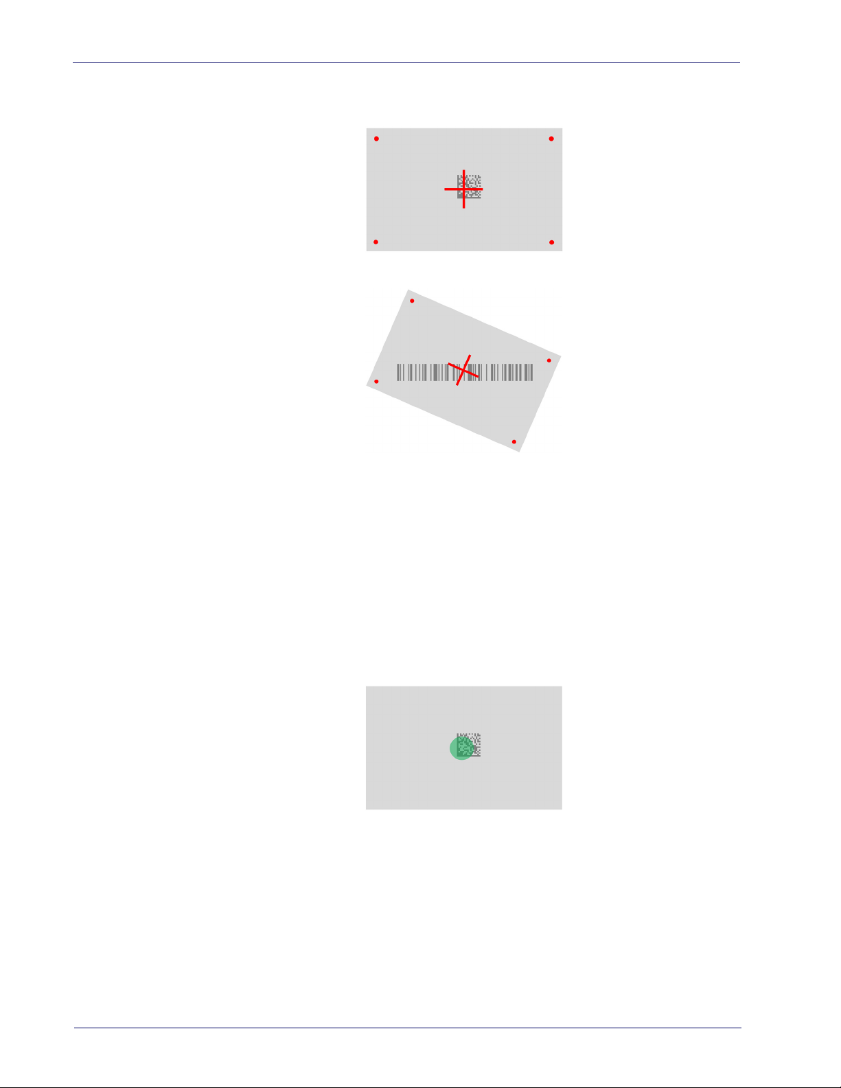
Using the RIDA DBT6400
The RIDA DBT6400 normally functions by capturing and decoding codes. The
aiming system is activated on trigger pull and indicates the center of the field of
view which should be positioned over the barcode:
Aiming System
Product Reference Guide 1
Page 10
Introduction
Linear barcode
2D Matrix symbol
Relative Size and Location of Aiming System Pattern
A beam illuminates the label. The projected pattern of the aiming system will be
smaller when the reader is closer to the barcode and larger when it is farther
from the code. Symbologies with smaller bars or elements (mil size) should be
read closer to the unit. Symbologies with larger bars or elements (mil size)
should be read farther from the unit.
If the aiming system is centered you will get a good read. Successful reading is
signaled by an audible tone plus a good read green spot LED indicator.
Relative Size and Location of Green Spot
2 RIDA™ DBT6400
Page 11

About this Manual
This Product Reference Guide (PRG) is provided for users seeking advanced
technical information, including connection, programming, maintenance and
specifications. The Quick Reference Guide (QRG) and other publications associated with this product are downloadable free of charge from the website listed
the back cover of this manual.
on
Typically, units are factory-programmed for the most common terminal and
ommunications settings. If you need to modify any programmable settings,
c
custom configuration can be accomplished by scanning the programming barcodes within this guide.
Programming can alternatively be perfor
Configuration application, which is available from the Datalogic website listed
on the back cover of this manual. This multi-platform utility program allows
device configuration using a PC. It communicates to the device using a serial or
USB cable and can also create configuration barcodes to print.
Overview
About this Manual
med using the Datalogic Aladdin™
Chapter 1, Introduction
cable connection information.
Chapter 2, Setup
ner, and interface configuration barcodes and details.
Chapter 3, Configuration Using barcodes
for customizing your scanner. There are different sections for interface types,
eral features, data formatting, and symbology-specific features.
gen
Chapter 4, References
Appendix A, Technical Specifications
as well as environmental and regulatory specifications. It also provides standard cable pin-outs and descri
scanner’s LED and Speaker indicators.
Appendix B, Standard Defaults
scanner features and options.
Appendix C, Sample barcodes
ogies.
Appendix D, Keypad
eter settings.
Appendix E, Scancode Tables
Wedge and USB Keyboard interfaces.
presents information about unpacking and setting up the scan-
provides a product overview, unpacking instructions, and
provides instructions and barcode labels
provides details concerning programmable features.
lists physical and performance characteristics,
ptions of the functions and behaviors of the
references common factory default settings for
offers sample barcodes of several common symbol-
includes numeric barcodes to be scanned for certain param-
lists control character emulation information for
Manual Conventions
The symbols listed below are used in this manual to notify the reader of key
issues or procedures that must be observed when using the scanner:
Notes contain information necessary for
and operating the scanner.
NOTE
Product Reference Guide
properly diagnosing, repairing
3
Page 12

Introduction
The CAUTION symbol advises you of actions th
ment or property.
CAUTION
Technical Support
Datalogic Website Support
The Datalogic website (
support and informatio
port, warranty information, product manuals, product tech notes, software
updates, demos
Reseller Technical Support
An excellent source for technical assistance and information is an authorized
Datalogic reseller. A reseller is acquainted with specific types of businesses,
application software, and computer systems and can provide individualized
assistance.
, and instructions for returning products for repair.
at could damage equip-
www.datalogic.com
n for Datalogic products. The site offers product sup-
) is the complete source for technical
Telephone Technical Support
If you do not have internet or email access, you may contact Datalogic technical
support at (541) 349-8283 or check the back cover of your manual for more
contact information.
Current versions of the Product Reference Guide (PRG), Quick Reference Guide
(QRG), the Datalogic Aladdin™ Configuration application, software/firmware and
any additional manuals, instruction sheets and utilities for this product can be
downloaded from the website listed on the back cover of this manual.
Alternatively, printed copies or product support CDs may be purchased through
your Datalogic reseller.
4 RIDA™ DBT6400
Page 13

Unpacking
Check carefully to ensure the scanner and any cables or accessories ordered are
present and undamaged. If any damage occurred during shipment, contact
Technical Support on page 4.
KEEP THE PACKAGING. Should the unit ever require service, it should be
re
turned in its original shipping container.
Setting Up the Reader
Follow the steps below to connect and get your reader up and communicating
with its Host.
1. Configure the Base Station (if available)
2. Charge the Batteries (see "Charging the Batteries" on page 7).
3. Link to a Host (see "Linking to a Host" on page 9) or to the Base Station (if
available - see "Linking to a Base St
Chapter 2
Setup
ation" on page 11).
4. Select the Interface Type for Base Station.
5. Configure the Reader (optional, depends on settings needed).
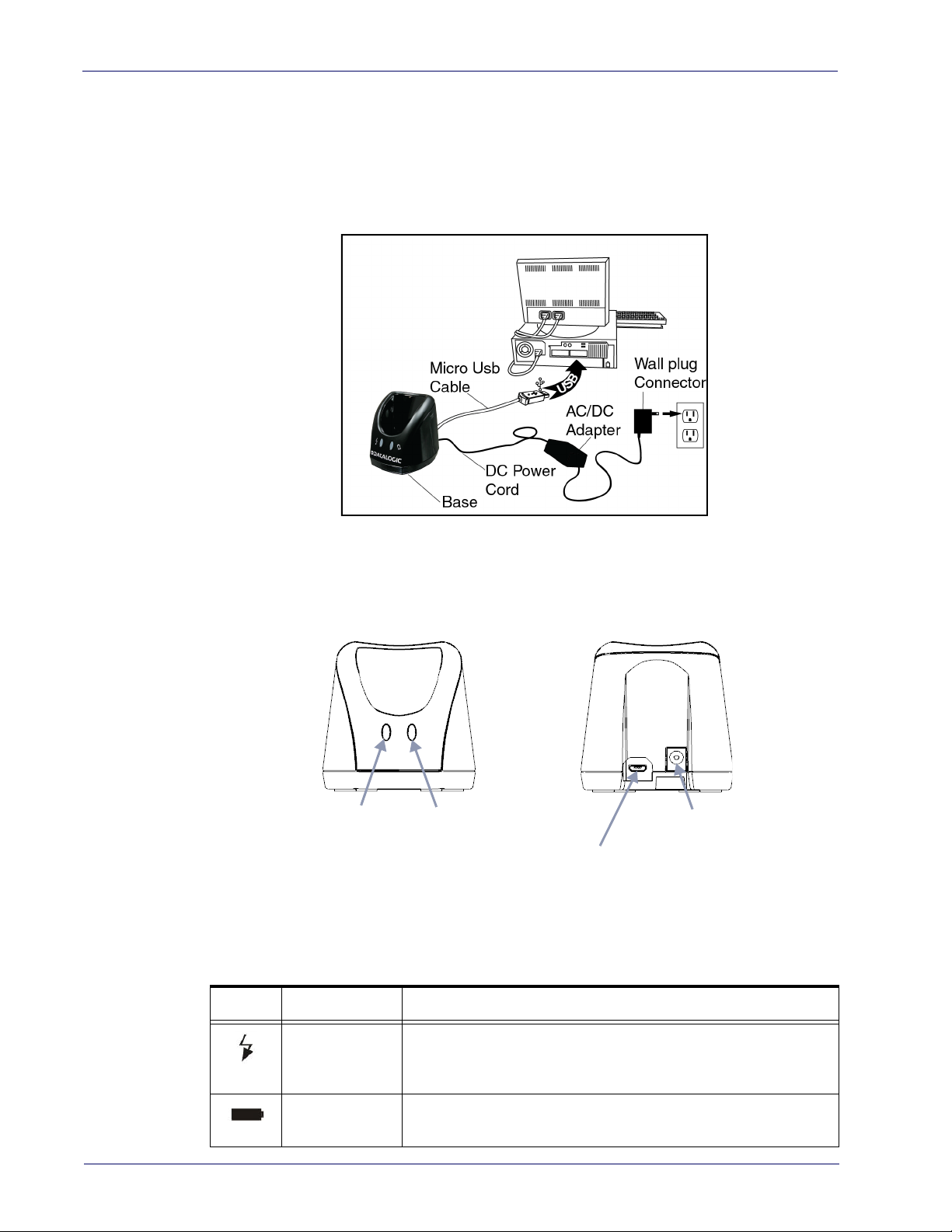
Configuring the BC6020 Base Station
Place the RIDA scanner on the Base Station as shown in the figure below.
Product Reference Guide 5
Page 14
Setup
Power On/
Data LED
Charging LED
Micro USB Cable
Connector
External Power
Connector
The Base Station can be powered up by an external power supply or by a Host
via the micro USB Cable. Both the power cable and the micro USB cable can be
connected at the same time on the Base; in this case, USB connection is used for
data exchange with the Host, while power is supplied from external power supply.
The figure below shows how to connect the Base Station to a terminal PC or to
another Host device.
Using the BC6020 Base Station
LEDs on BC6020 Base Station provide information about the Base as well as the
battery charging status, as shown in the figure below.
The behaviour and meaning of the LEDs are summarized in Table 1:
Table 1.
Radio Base LEDs
LED Status
Yellow On = base is powered.
Power On/ Data
Charging + Charge
completed
6 RIDA™ DBT6400
Yellow Blinking = base receives data and commands from the Host
or the reade
Green On = Power provided to the scanner fo
r.
r battery charging.
Charging indications are shown by the scanner.
Page 15

Charging the Batteries
Micro-USB
Connector
Before using the DBT6400 for the first time, it is necessary to charge the battery.
The battery can be charged by
the micro-USB connector. You can use the provided USB cable for this purpose.
.
Alternatively, the battery can be charged using:
1. the Base Station BC6020.
2. the charging-only cradle CHR-DBT60, available as an optional.
To charge the battery with the Base Station, insert the reader into the base.
When the scanner detects the base it will sound to indicate the correct placement.
When in charge, the side LEDs on the reade
If the battery is very depleted, the reader could stay in a precharge phase with
the top led blinking red. This phase automatically ends when the battery charge
is enough to power up the reader, in case the battery charging is not completed.
Battery charging indications are shown on the side band LEDs. While charging,
the side band LEDs blink
LEDs remain solid green.
Setting Up the Reader
connecting the reader directly to a Host through
r indicate the status of the battery.
green; when the battery is fully charged, the side band
.
Before using the Battery, read “Battery Safety”
in the Safety and Regulatory
Addendum. Datalogic recommends annual replacement of rechargeable battery
packs to ensure maximum performance.
NOTE
Product Reference Guide
7
Page 16
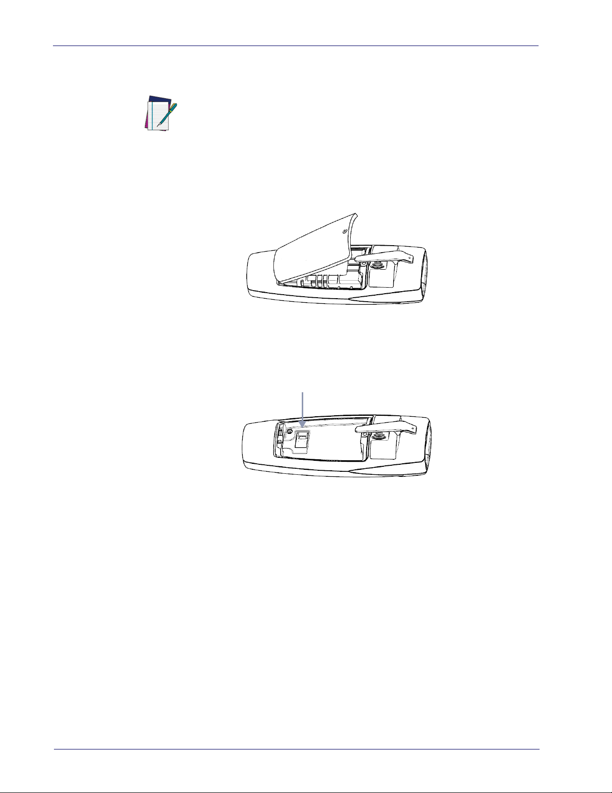
Setup
Battery Connector
Replacing the Battery Pack
Before proceeding, read “Battery Safety” in the Safety and Regulatory Addendum. Datalogic recommends annual replace
to ensure maximum performance.
NOTE
1. Use a T5 type screwdriver to unscrew the cover of the battery pack until it
is disengaged.
ment of rechargeable battery packs
2. Pull up the battery pack and disconnect the cable from the battery connector. For this operation you can use a plastic nipper. If under the battery
ere is any label that covers the battery connector, remove it.
th
To mount the new battery pack reverse the process. Restore the label under the
battery if it was present. Use the new one included in battery spare part.
8 RIDA™ DBT6400
Page 17

Linking to a Host
Link to Host in SPP mode
Link to Host in HID mode
The RIDA DBT6400 is equipped with Bluetooth® Wireless Technology. To set up
the scanner for communication with a Host the user shall select the Profile
Mode.
The available Profile Mode for standard Bluetooth are:
• Bluetooth Serial Port Profile (SPP)
• Bluetooth HID Profile (default)
Scan one of the following barcodes to select the desired Profile Mode:
.
Linking to a Host
After reading one of the above profile label, the scanner, if already connected to
a Host, will unlink.
If the profile label is read when the rea
der is already connected to a Host, the
scanner will first unlink and then apply the new profile.
NOTE
After reading the profile label t
he scanner will become discoverable by the Host.
Bluetooth Pairing
To pair with a Bluetooth enabled Host:
1. Press the scan button to wake up the reader.
2. Press the Link button. The blue LED blin
discoverable by the Host. Alternatively, you can read one of the profile
labels (see "Linking to a Host" on page 9) and the reader will become automatically discoverable by the Host.
3. On the Host, use the dedicated Blueto
devices. Select the RIDA scanner from the list of available devices. If you
receive an error message, it may be necessary to disable security on the
device.
king indicate that the scanner is
oth application to search for new
Product Reference Guide
4. When the scanner ends the pairing with the Host the blue LED remains on.
nding on the Bluetooth profile, you can check the connection:
Depe
A. For SPP: use an RS-232 terminal program to see incoming data on the
port designated by
the Host Bluetooth application (Bluetooth outgoing
COM port).
B. For HID: use a text editor to see incoming data on the Host.
9
Page 18
Setup
Unlink
\x0d
Passkey END
\x7f
Passkey Restart
Passkey Abort
The DBT6400 reader can be set up to requi
re a PIN code when connecting. If you
want to set up a PIN, or add new equipment to a system that uses a custom
security PIN, please see "BT Security Features" on page 262.
NOTE
Bluetooth Unpairing
To unpair the reader and the Host, press and hold the Link button until the blue
LED turns off.
Alternatively, read the following unlink label.
Before pairing to another Host, the reader mu
st be unpaired from the previous.
NOTE
Bluetooth Passkey Request
During the pairing process, based on Host and Reader security settings, you
may need to enter a passkey.
If you let the Host generate the passkey, simply enter the required code by
nning the corresponding barcodes for alphanumeric entry. Complete by
sca
scanning the End label. To restart the entering of the passkey, read the Restart
label. To abort entering of passkey read Abort.
If, alternatively, you choose to enter on the Host the passkey proposed by the
ader, enter 1234.
Re
HID Country Mode
When the Reader is connected with a Bluetooth Application in HID mode, you
may want to set the country for which your Host is localized. Go to "HID Country Mode" on page 266” and read one of the configuration command labels.
10 RIDA™ DBT6400
Page 19

Linking to a Base Station
Unlink
Linking to a Host in Initiator Mode
The reader can optionally be linked to a host as initiator (also called Client
Mode or Master Mode). This kind of link can be done in all the available profiles.
To do this, follow these steps:
1. Ensure the host is powered and has the Bluetooth feature enable.
2. Identify the Bluetooth address i
n the Host/adapter device.
3. Create a Link label that contains the address of the Host/adapter. The link
abel is a Code 128 function 3 label having the following format for SPP
l
connection:
<FN3 char>LnkB<12 character Bluetooth address>
And the following format for HID connection:
<FN3 char>LnkHid<12 character Bluetooth address>
4. Scan the link label you created in step 3.
5. Complete the procedure to establish the connection. For the SPP mode you
eed to open the associated incoming COM port.
n
Example: if you want to connect to a tablet wi
th BT Address 00:1A:7D:DA:71:13
the label content in order to connect in SPP profile is:
<FN3 char>LnkB001A7DDA7113
To connect in HID profile:
<FN3 char>LnkHid001A7DDA7113.
To easily switch between different Host is suggested to keep default security level.
NOTE
Note: Some Host cannot accept connection using HID profile in initiator
mode.
NOTE
Linking to a Base Station
The RIDA DBT6400 can be used paired with its Base Station. The data received
over the RF link will be exchanged with the Host using the USB interface of the
Base Station. In this case, before configuring the interface, it is necessary to link
the scanner to the Base Station.
To link the handheld and the base, press the Scan button to wake up the reader
d then insert the reader into the Base station. A beep will indicate the suc-
an
cessful pairing.
If the reader was previously linked to another base or host, you must first scan
e Unlink barcode before linking to the new base.
th
r
Product Reference Guide
11
Page 20
Setup
Base Station Interface Selection
Upon completing the physical connection between the base and its host, proceed directly to Interface Selection to select the kind of USB interface type the
e is connected to; scan the appropriate barcode for your system’s interface
bas
type.
The base will support the foll
• USB COM to simulate RS-232 standard interface
• USB-OEM (can be used for OPOS/UPOS/JavaPOS)
• USB Keyboard
• USB Composite (KEYBOARD + COM)
For defaults and additi
to the corresponding chapter in the Product Reference Guide.
Configuring the Interface
Scan the programming barcode which selects the appropriate interface type for
the system the reader will be connected to.
Unlike some other programming features and options, interface selections
require that you scan only one programming barcode label. DO NOT scan an
ENTER/EXIT barcode prior to scanning an interface selection barcode.
NOTE
onal information associated with each interface, proceed
owing USB host interfaces:
USB INTERFACES
USB COM to simulate RS-232 standard interface
Select USB-COM-STD
a
USB-OEM
(can be used for OPOS/UPOS/JavaPOS)
Select USB-OEM
USB Keyboard
Select USB Keyboard
USB Composite
Select USB Composite
a
a. Download the correct USB COM driver from www.datalogic.com.
12 RIDA™ DBT6400
Page 21

Customizing Configuration Settings
Using the Programming barcodes
This manual contains feature descriptions and barcodes which allow you to
reconfigure your scanner. Some programming barcode labels, like
Product Configuration to Defaults"
label to enact the change. M
ever, require the scanner to be placed
them. Scan an ENTER/EXIT barcode once to enter Programming Mode. Once the
scanner is in Programming Mode, you can scan a number of parameter settings
before scanning the ENTER/EXIT barcode a second time, which will then accept
your changes, exit Programming Mode and return the scanner to normal operation.
on page 15, require only the scan of that single
ost of the programming labels in this manual, how-
Customizing Configuration Settings
"Resetting the
in Programming Mode prior to scanning
There are some exceptions to the typ
described above. Please read the description and setting instructions
carefully when configuring each given programmable feature.
NOTE
ical programming sequence
Datalogic Aladdin™ Utility
Programming can alternatively be performed using the Datalogic Aladdin™
Configuration application which is available for free download from the Datalogic website listed on the back cover of this manual. This multi-platform utility
ogram allows device configuration using a PC. It communicates to the device
pr
using a serial or USB cable and can also create configuration barcodes to print.
Datalogic Aladdin™ is a multi-platform utility program providing a quick and
use
r-friendly configuration method via the RS-232/USB-COM interface. The
Aladdin utility is available on the Datalogic website. Aladdin allows you to program the scanner by selecting configuration commands through a user-friendly
phical interface running on a PC. These commands are sent to the scanner
gra
over the selected communication interface, or they can be printed as barcodes
to be scanned.
Aladdin also provides the ability to perform a software upgrade for the connected device (see the Datalogic Aladdin™ Help On-Line for more details).
Product Reference Guide
13
Page 22

Setup
Transmit Software Version
RevA
Interface Settings
The scanner and the base station (if available) are typically factory-configured
with a set of default features standard to the interface type you ordered. See
"Base Station Interface Selection"
Global Interface Features, starting on page 23
base station interface types. If your installation requires you to further customize your scanner, you can select other options through use of the instructions
and prog
face.
•
•
•
ramming barcodes available in the appropriate section for your inter-
USB-COM Interfaces, starting on page 25
Keyboard Interface, starting on page 35
USB-OEM Interface, starting on page 65
Configuring Other Features
If your installation requires different programming than the standard factory
default settings, the following sections of this manual allow configuration of
non-interface-specific settings you might require:
Configuration Using barcodes: General Features includes programming for scan-
ning, speaker and LED indicators and other such universal settings.
on page 12.
provides settings configurable by all
Reading Parameters: Reading Parameters include programming for scanning,
speaker and LED indicators and other universal settings.
1D Symbologies: Includes options concerning the barcode label types (symbolo-
gies). These settings allow you to enable/disable symbologies, set label
ngths, require check digit, etc.
le
Software Version Transmission
The software version of the device can be transmitted over the wireless BT
Scanner Profile interfaces or the USB Base Station interfaces by scanning the
following label.
14 RIDA™ DBT6400
Page 23
Customizing Configuration Settings
$P,HA00,P
Restore Custom Default Configuration
Restore USA Factory Configuration
$P,AE,P
Restore EU Factory Configuration
$P,Ae,P
Resetting the Product Configuration to Defaults
If you aren't sure what programming options are in your scanner, or you've
changed some options and want to restore the Custom Default Configuration
that may have been saved in the scanner, scan the
uration
rently active interface.
barcode below. This will restore the custom configuration for the cur-
Custom defaults are based on the interface type. Configure the scanner for
the correct interface before scanning this label.
NOTE
If you aren't sure what programming options are in your scanner, or you've
changed some options and want to restore the Factory Configuration, you have
two options. You can scan the
Restore EU Factory Configuration
configuration to the factory settings including the interface type. The USA label
stores Label IDs to those historically used in the USA. The EU label restores
re
Label IDs to those historically used in Europe. The Label ID sets for USA and EU
are shown in the Label ID section of this manual.
Restore USA Factory Configuration
barcode below. Both labels restore the scanner
Restore Custom Default Config-
barcode or the
Scanning either of the “Restore Factory Configuration” commands below
will result in the loss of any custom configuration settings for your device.
CAUTION
The programming section on the following pages lists the factory default settings for each of the menu commands (indicated by shaded blocks and bold
te
xt).
Product Reference Guide
15
Page 24

Setup
Compatibility
Supported BT Specification
The Rida Bluetooth radio is fully compatible with the following Bluetooth specifications:
• Bluetooth v2.1 + EDR
• Bluetooth v3.0 + HS
• Bluetooth v4.0
• Bluetooth v4.1
For more details on connection with devices compliant with older BT specifications, please refer to the PRG.
Device and operative system supported
In general, the Rida supports connection with devices and Bluetooth radio
stacks compliant with the above specifications (see
on page 16) that are able to support HID Host and/or SPP profile.
This is a non-exhaustive list of supported operating systems:
•iOS
•Android
• Windows (7, 8, 8.1, 10)
• Windows XP (Microsoft, Broadcom, and other commonly available Bluetooth stacks)
• Windows Phone 8.1 Update 2 (only for HID profile)
• Windows 10 Mobile
• Mac OS X 10.11
Note that:
• Windows XP Service Pack 2 and SP3 releases work natively with Bluetooth
v1.1, v2.0 and v2.0+EDR. To connect with Rida, the Windows XP stack
must be replaced by a third party stack that supports newer Bluetooth ver
sions.
• Windows 7 works with Bluetooth v2.1+EDR. Bluetooth stack supports vendor-supplied additional profiles without requiring that the Microsoft stack
be replaced. Due to the driver stack, used passkey could be required
during pairing process.
"Supported BT Specification"
-
16 RIDA™ DBT6400
Page 25

Tested Devices
This is a non-exhaustive list of tested devices:
Type Device Note
Compatibility
Laptop
Tablet and
Smartphone
Dongle
For an updated list, please refer to the company website.
HP EliteBook 8460p
HP EliteBook 8460p Windows 7, native BT Software Stack
MacBook Air 2015 Mac OS X 10.11, built in BT radio
Dell Latitude E7450 Windows 7, built in BT radio
iPad Mini 4 iOS9
iPhone 3Gs iOS 6
Motorola Nexus 6 Android 6.0
Samsung Galaxy Tab S SMT805 Android 5.0
Huawei Honor 4C Android KitKat
NOKIA LUMIA 640 XL Windows Phone 8.1 Update 2
Samsung Galaxy S5 (SM-G900F) Android 6.0.1
Sitecom Usb Adapter Bluetooth 4.0
Sitecom Usb Adapter Bluetooth 4.0 Windows 7 native BT Software Stack
Windows 7, built in BT radio (WIDCOMM BT Stack)
CSR Harmony Wireless Software
Stack on W
indows 7
Product Reference Guide
17
Page 26
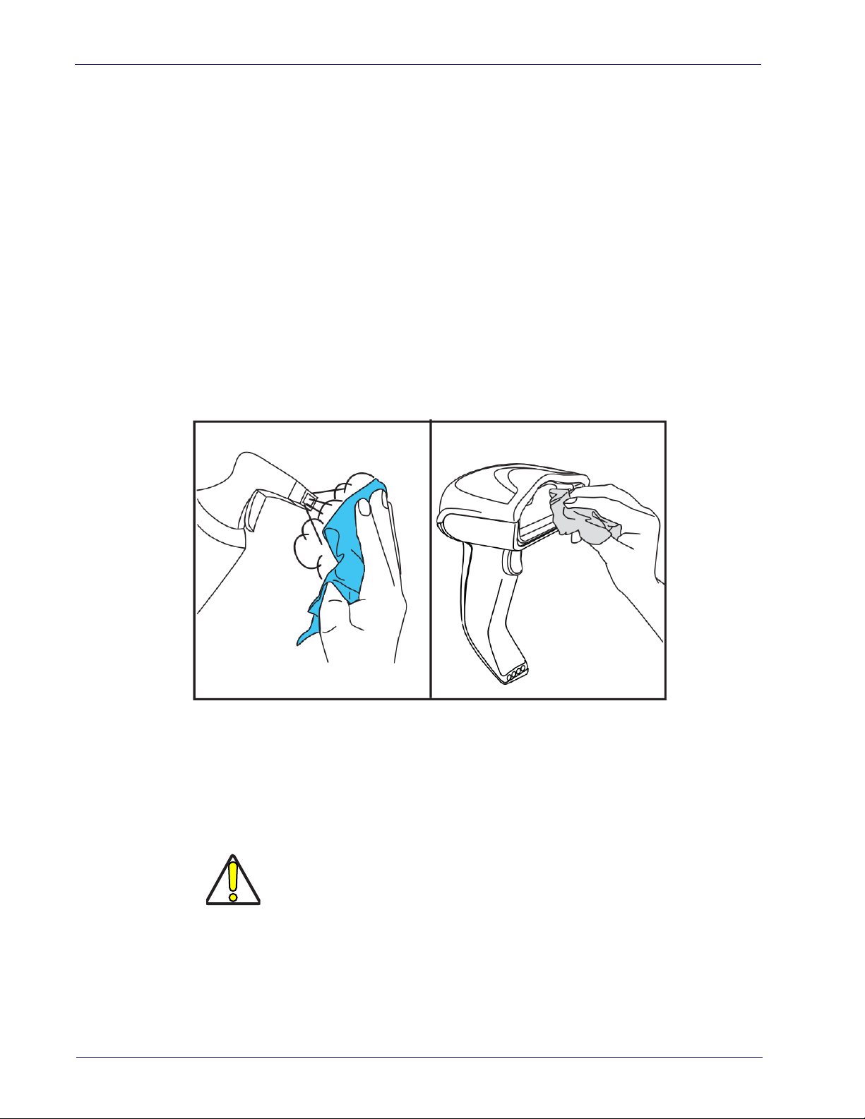
Setup
Cleaning Procedure
Proper cleaning is needed on the external plastic surfaces, output window and
electrical contacts to guarantee reliable scanning and charging of the battery.
A regular cleaning routine will remove the dust and dirt that may accumulate on
the product over time. The maintenance activity may be repeated more frequently depending on the severity of the environment in which the scanner is
d.
use
A periodic deeper cleaning is suggested once per month.
Cleaning plastic surfaces
Exterior plastic surfaces and scan windows exposed to spills, smudges or
debris require periodic cleaning to ensure best performance during scanning.
Use a soft, dry cloth to clean the product.
If the product is very soiled, clean the plastic surfaces with a soft cloth moistened with a diluted non-aggressive cleaning solution or isopropyl alcohol (minimum 70%).
Recommended cleaners for standard plastics are:
Formula 409® glass and surface cleaner, dish soap and water, Windex® Original
(Blue).
Recommended cleaners for H
CaviWipes™, diluted Clorox® bleach,Hepacide Quat® II,Sani-Cloth®,Virex® II
2
56.
Do not use abrasive or aggressive cleansing agents or abrasive pads to clean
scan windows, contacts or plastics.
Do not spray or pour liquids directly onto the unit.
CAUTION
Be sure to turn off power and unplug the dev
cleaning.
Be sure to dry up the device
Cleaner and liquids may be harsh on metal c
for use only on enclosures.
ealth care plastics:
ice from electrical outlet before
before powering it up.
ontacts. They are recommended
18 RIDA™ DBT6400
Page 27

Cleaning electrical contact surfaces
Regular cleaning of electrical contacts is needed to guarantee a correct
recharging of the battery. Both scanner and cradle contacts should be cleaned.
In case spills, smudges or debris accumulate on the cradle and/or the scanner,
proper operation could be affected and a periodical cleaning is recommended
as follows.
Avoid the use of brushes or any other hard tool to remove grime from electrical
c
ontacts, since these may damage or scratch the contact's plating.
Scanner Contacts
• Use a soft dry cloth to clean the contact area and the plastic surface
around the contacts.
• Be sure to remove dust, dirt and any cloth res
• If the level of grime is significant, it is suggested the use of a soft white or
pink pencil eras
green and yellow directions.
er to gently rub the contacts. Motion can be along both the
Cleaning Procedure
idue.
• Be sure to remove the rubber residuals by gently blowing them off with
clean compressed air.
Be careful when using compressed air: protect yourself with goggles and
point the nozzle far from eyes and not too close to the scanner surface.
Read previously the warning label on the spray can.
CAUTION
Cradle Contacts
• Use a soft dry cloth to clean the contact area and the plastic surface
around the contacts.
• Particular attention must be paid to
due. Do not allow this material t
• It is suggested the use of a soft white or pink pencil eraser to gently rub
e contacts. Cradle contacts should be cleaned with a motion along the
th
yellow direction.
remove dust, dirt and any cloth resi-
o fall again onto the contacts.
Product Reference Guide
19
Page 28

Setup
• Be sure to remove the rubber residuals by gently blowing them off with
clean compressed air.
Scanner and cradle deep cleaning
In case some hard grime, grease or liquid residual are present on electrical
contacts, a deeper cleaning may be needed. If the above procedure is not
enough to guarantee proper working of the system, the use of isopropyl alcohol
is suggested (minimum 70%).
In this case it is suggested to use a cotton tipped applicator wit
alcohol, gently wiping along the pins of the electrical connection. Be sure that
cotton residue is not left on any pin of the electrical contacts.
h isopropyl
Remove power before initiating the deep cleaning routine.
After completion of the deep cleaning routine allow the system to dry completely
before reconnecting to power. Depending on the environmental conditions wait at
least 30 minutes or, if possible, leave the system unpowered overnight.
20 RIDA™ DBT6400
Page 29

Chapter 3
Configuration Using barcodes
This and following sections provide programming barcodes to configure your
scanner by changing the default settings. For details about additional methods
of programming, see "
Customizing Configuration Settings" on page 13
.
You must first enable your scanner to rea
this section. If you have not done this, go to
NOTE
and complete the appropriate procedure.
Configuration Parameters
Once the scanner is set up, you can change the default parameters to meet your
application needs. Refer to "
15
for initial configuration in order to set the default values and select the
interface for your application.
The following configuration parameters are divided into logical groups, making
easy to find the desired function based on its reference group.
it
Interface Configuration:
• "USB-COM Interfaces" on page 25
• "Keyboard Interface" on page 35
• "USB-OEM Interface" on page 65
Parameters common to all interface applications:
• "
Global Prefix/Suffix" on page 68
• "
Data Format" on page 67
ization of scanned data output.
• "
Reading Parameters" on page 79
cators status functioning.
d barcodes in order to use
Setup, starting on page 5
Resetting the Product Configuration to Defaults" on page
offers advanced configuration options for custom-
control various operating modes and indi-
Symbology-specific parameters:
"1D Symbologies" on page 105
the programming barcodes necessary for configur
You must first enable your scanner to read barcodes in order to use
this section. If you have not done this, go to
and complete the appropriate procedure.
NOTE
defines options for all symbologies and provides
ing these features.
Setup, starting on page 5
Product Reference Guide 21
Page 30

Enter/Exit Programming Mode
To program features:
1. Scan the ENTER/EXIT PROGRAMMING barcode, available at the top of each
programming page, when applicable.
2. Scan the barcode to set the desired progr
to cover unused barcodes on the page, and possibly the facing page, to
ensure that the scanner reads only the barcode you intend to scan.
3. If additional input parameters ar
scan the appropriate characters from the keypad.
e needed, go to
amming feature. You may need
Appendix D, Keypad
, and
Additional information about many features can be found in the “References” chapter.
NOTE
4. Complete the programming sequence by scanning the ENTER/EXIT PROGRAMMING barcode to exit Programming Mode.
For more detailed descriptions, programming information an
setting selected configuration items, see
If you make a mistake before the last character, scan the CANCEL barcode to abort and not save the entry string. You can then start again at
th
e beginning.
d examples for
References, starting on page 235
.
22 RIDA™ DBT6400
Page 31

Global Interface Features
DEFAULT
The following interface features are configurable by all interface types. To set
features specific to your interface, turn to that section of this manual.
Enter/Exit Programming Mode
HOST COMMANDS — OBEY/IGNORE
USB SUSPEND MODE
on page 24
Host Commands — Obey/Ignore
This option specifies whether the scanner will obey or ignore host commands.
When set to ignore, the scanner will ignore all host commands except for those
necessary for:
•service mode
• flash programming mode
•keeping the inte
• transmission of labels.
rface active
on page 23
$CIFIH00
Host Commands = Obey
$CIFIH01
Host Commands = Ignore
Product Reference Guide
23
Page 32

Enter/Exit Programming Mode
DEFAULT
USB Suspend Mode
This setting enables/disables the ability of the USB interface to enter suspend
mode.
$CUSSE01
USB Suspend Mode = Enable
$CUSSE00
USB Suspend Mode = Disable
24 RIDA™ DBT6400
Page 33

USB-COM Interfaces Enter/Exit Programming Mode
USB-COM Interfaces
The programming barcodes in this chapter allow modifications to the standard
RS-232 / USB-Com interfaces.
STAND AR D FACTORY SETTINGS on page 25
INTERCHARACTER DELAY on page 26
BEEP ON ASCII BEL on page 27
BEEP ON NOT ON FILE on page 27
ACK NAK OPTIONS on page 28
ACK CHARACTER on page 29
NAK CHARACTER on page 29
ACK NAK TIMEOUT VALUE on page 30
ACK NAK RETRY COUNT on page 31
ACK NAK ERROR HANDLING on page 32
INDICATE TRANSMISSION FAILURE on page 33
DISABLE CHARACTER on page 33
ENABLE CHARACTER on page 34
Standard Factory Settings
Reference Appendix B, for a listing of standard factory settings.
Product Reference Guide
25
Page 34

Enter/Exit Programming Mode Intercharacter Delay
00 = No Intercharacter Delay
Intercharacter Delay
This parameter specifies the intercharacter delay between the end of one character and the beginning of the next. The delay can be set within a range of zero
) to 990 milliseconds in 10ms increments. A setting of zero specifies no
(0
delay. See "Label ID: Pre-loaded Sets" on
ming instructions.
page 238 for more detailed program-
$CR2IC00
Intercharacter Delay = No Delay
$CR2IC
Select Intercharacter Delay Setting
Make a mistake? Scan the CANCEL barcode to abort and not
save the entry string. You can then start again at the
beginning.
DEFAULT
To configure this feature, scan the ENTER/EXIT barcode
above, then the barcode at left followed by digits from
the Alphanumeric characters in
representing your desired character(s). End by
pad
scanning the ENTER/EXIT barcode again.
CANCEL
Appendix D, Key-
~
26 RIDA™ DBT6400
Page 35

USB-COM Interfaces Enter/Exit Programming Mode
DEFAULT
Beep On ASCII BEL
When this parameter is enabled, the scanner issues a beep when a <BEL> character is detected on the RS-232 serial l
attention to an illegal entry or other important event.
$CR2BB00
Beep On ASCII BEL = Disable
ine. <BEL> is issued to gain a user's
DEFAULT
$CR2BB01
Beep On ASCII BEL = Enable
Beep On Not on File
This option enables/disables the action of the scanner to sound a three beep
sequence upon receiving a Not-On-File (NOF) host command.
$CBPNF00
Beep On Not On File = Disable
$CBPNF01
Beep On Not On File = Enable
Product Reference Guide
27
Page 36

Enter/Exit Programming Mode ACK NAK Options
ACK NAK Options
This enables/disables the ability of the scanner to support the RS-232 ACK/
NAK protocol. When configured, the scanner and/or host sends an “ACK” when
it receives data properly, and sends “NAK” when the data is in error.
Options are:
•Disable
• Enable for label transmission — The scanner expects an ACK/NAK
response from the host when a label is sent.
• Enable for host-command acknowledge — The scanner will respond with
ACK/NAK when the host sends a command.
• Enable for label transmission and host-command acknowledge
$CR2AE00
DEFAULT
ACK/NAK Protocol = Disable ACK/NAK
$CR2AE01
ACK/NAK Protocol = Enable for label transmission
$CR2AE03
ACK/NAK Protocol = Enable for label transmission and host-
command acknowledge
$CR2AE02
ACK/NAK Protocol = Enable for host-command
acknowledge
28 RIDA™ DBT6400
Page 37

USB-COM Interfaces Enter/Exit Programming Mode
0x06 ‘ACK’ Character
0x15 ‘NAK’ Character
ACK Character
This setting specifies an ASCII character or hex value to be used as the ACK
character. ASCII characters or any hex value from 0 to 0xFF can be selected. See
"ACK Character" on
NOTE
$CR2AC
Select ACK Character Setting
page 227 for more detailed programming instructions.
Setting to previously defined characters such as XON, XOFF, or
host commands conflicts with normal operation of these characters.
NAK Character
This setting specifies an ASCII character or hex value to be used as the NAK
character. ASCII characters or any hex value from 0 to 0xFF can be selected. See
"NAK Character" on
Select NAK Character Setting
DEFAULT
page 227 for more detailed programming instructions.
Setting to previously defined characters such as XON, XOFF, or
host commands conflicts with normal operation of these characters.
NOTE
$CR2NA
DEFAULT
Product Reference Guide
29
Page 38

Enter/Exit Programming Mode ACK NAK Options
DEFAULT
01 ACK NAK Timeout value is 200ms
ACK NAK Timeout Value
This option specifies the amount of time the scanner waits for an ACK character
from the host following label transmission. The selectable timeout range is 200
milliseconds to 15,000ms (15 seconds) in 200ms increments. A selection of 0
disables the timeout. See "ACK NAK Timeout Value" on
detailed programming instructions.
page 229 for more
$CR2AT
Select ACK NAK Timeout Value Setting
Make a mistake? Scan the CANCEL barcode to abort and
not save the entry string. You can then start again at the
beginning.
To configure this feature, scan the ENTER/EXIT barcode
above, then the barcode at left followed by digits from
the Alphanumeric characters in
representing your desired character(s). End by
pad
scanning the ENTER/EXIT barcode again.
CANCEL
Appendix D, Key-
~
30 RIDA™ DBT6400
Page 39

USB-COM Interfaces Enter/Exit Programming Mode
003 = 3 Retries
ACK NAK Retry Count
This feature specifies the number of times the scanner retries a label transmission due to a retry condition. The selectable range is from 1 to 254 retries. A
lection of 0 disables the count, and a selection of 255 specifies unlimited
se
retries. See "ACK NAK Retry Count" on
ming instructions.
page 230 for more detailed program-
$CR2AR
Select ACK NAK Retry Count Setting
Make a mistake? Scan the CANCEL barcode to abort and
not save
beginning.
the entry string. You can then start again at the
DEFAULT
To configure this feature, scan the ENTER/EXIT barcode
above, then the barcode at left followed by digits from
the Alphanumeric characters in
representing your desired character(s). End by
pad
scanning the ENTER/EXIT barcode again.
CANCEL
Appendix D, Key-
~
Product Reference Guide
31
Page 40

Enter/Exit Programming Mode ACK NAK Options
ACK NAK Error Handling
This feature specifies the method the scanner uses to handle receive errors
detected while waiting for an ACK character from the host.
Options are:
• Ignore errors detected
• Process error as valid ACK character
• Process error as valid NAK character
$CR2EH00
DEFAULT
ACK NAK Error Handling = Ignore Errors Detected
$CR2EH01
ACK NAK Error Handling = Process Error
d ACK Character
as Vali
$CR2EH02
ACK NAK Error Handling = Process Error
Valid NAK Character
as
32 RIDA™ DBT6400
Page 41

USB-COM Interfaces Enter/Exit Programming Mode
0x44 = Disable Character is ‘D’
Indicate Transmission Failure
This option enables/disables the scanner’s ability to sound an error beep to
indicate a transmission failure while in ACK/NAK mode
Indicate Transmission Failure = Disable Indication
$CR2TF01
Indicate Transmission Failure = Enable Indication
.
$CR2TF00
DEFAULT
Disable Character
Specifies the value of the RS-232 host command used to disable the scanner.
ASCII characters or any hex value from 0 to 0xFF can be selected. See "Disable
Character" on
NOTE
$CR2DC
Select Disable Character Setting
DEFAULT
page 231 for more detailed programming instructions.
Setting to previously defined characters such as XON, XOFF, or
host commands conflicts with normal operation of these characters.
Product Reference Guide
33
Page 42

Enter/Exit Programming Mode Enable Character
0x45 = Enable Character is ‘E’
Enable Character
Specifies the value of the RS-232 host command used to enable the scanner.
ASCII characters or any hex value from 0 to 0xFF can be selected. See "Enable
Character" on
NOTE
$CR2EC
Select Enable Character Setting
page 232 for more detailed programming instructions
Setting to previously defined characters such as XON, XOFF, or
host commands conflicts with normal operation of these characters.
DEFAULT
.
34 RIDA™ DBT6400
Page 43

Keyboard Interface
Use the programming barcodes in this chapter to select options for USB Keyboard. Reference Appendix B, for a listing of standard factory settings. Information about control character emulation which applies to keyboard interfaces
listed in Appendix E, Scancode Tables.
is
COUNTRY MODE on page 36
CAPS LOCK STATE on page 58
NUMLOCK on page 59
KEYBOARD NUMERIC KEYPAD on page 59
KEYBOARD SEND CONTROL CHARACTERS on page 60
INTERCHARACTER DELAY on page 61
INTERCODE DELAY on page 62
USB KEYBOARD SPEED on page 63
Product Reference Guide 35
Page 44

Enter/Exit Programming Mode Country Mode
Country Mode
This feature specifies the country/language supported by the keyboard.
The Country Mode setting is ignored if the interface uses alternate key encod-
ing.
Setup on PC to use ALT Universal
1. Open Registry Edit
2. Set EnableHexNumpad to 1 as follows:
3. Reset the PC.
36 RIDA™ DBT6400
Page 45

Keyboard Interface Enter/Exit Programming Mode
Setting Country Mode
This feature specifies the country/language supported by the keyboard. Country Modes are only valid for the following interfaces:
• USB Keyboard (without alternate key encoding)
•BT HID
$CKBCO00
DEFAULT
United States
$CKBCO01
French International (Belgian French)
$CKBCO02
$CKBCO11
Danish
$CKBCO03
German
United Kingdom
$CKBCO0E
French (France)
$CKBCO04
Italian
Product Reference Guide
37
Page 46

Enter/Exit Programming Mode Country Mode
Setting Country Mode (continued)
$CKBCO0F
Norwegian
$CKBCO09
Portuguese Portugal
$CKBCO0A
Spanish
$CKBCO0B
Swedish
$CKBCO14
Japanese ASCII
$CKBCO13
Swiss French
$CKBCO13
Hungarian
38 RIDA™ DBT6400
Page 47

Keyboard Interface Enter/Exit Programming Mode
Setting Country Mode (continued)
$CKBCO0F
Czech
$CKBCO09
SlovaK
$CKBCO0A
Romanian
$CKBCO0B
Croatian
$CKBCO14
Canadian French Win7
$CKBCO13
Polish_214
$CKBCO13
Lithuanian
Product Reference Guide
39
Page 48

Enter/Exit Programming Mode Country Mode
Setting Country Mode (continued)
$CKBCO0F
Vietnamese
$CKBCO09
Russian
$CKBCO0A
Arabic 101
$CKBCO0B
Chinese ASCII
$CKBCO14
Albanian
$CKBCO13
Thai-Kedmanee
$CKBCO13
Arabic 102
40 RIDA™ DBT6400
Page 49

Keyboard Interface Enter/Exit Programming Mode
Setting Country Mode (continued)
$CKBCO0F
Arabic 102 AZERTY
$CKBCO09
Azeri Cyrillic
$CKBCO0A
Azeri Latin
$CKBCO0B
Belarusian
$CKBCO14
Bosnian Latin
$CKBCO13
Bosnian Cyrillic
$CKBCO13
Bulgarian Cyrillic
Product Reference Guide
41
Page 50

Enter/Exit Programming Mode Country Mode
Setting Country Mode (continued)
$CKBCO0F
Bulgarian Latin
$CKBCO09
Canadian French (Legacy)
$CKBCO0A
Canadian Multilingual
$CKBCO0B
Chinese (Simplified)
$CKBCO14
Czech Programmers
$CKBCO13
Chinese (Traditional)
$CKBCO13
Czech QWERTY
42 RIDA™ DBT6400
Page 51

Keyboard Interface Enter/Exit Programming Mode
Setting Country Mode (continued)
$CKBCO0F
Dutch Netherland
$CKBCO09
Estonian
$CKBCO0A
Faeroese
$CKBCO0B
Finnish
$CKBCO14
French (Canada) 95/98
$CKBCO13
French (Canada) 2000/XP
$CKBCO13
Galician
Product Reference Guide
43
Page 52

Enter/Exit Programming Mode Country Mode
Setting Country Mode (continued)
$CKBCO0F
Greek
$CKBCO09
Greek Latin
$CKBCO0A
Greek Polytonic
$CKBCO0B
Greek220
$CKBCO14
Greek319
$CKBCO13
Greek220 Latin
$CKBCO13
Greek319 Latin
44 RIDA™ DBT6400
Page 53

Keyboard Interface Enter/Exit Programming Mode
Setting Country Mode (continued)
$CKBCO0F
Hebrew Israel
$CKBCO09
Hungarian_101KEY
$CKBCO0A
Icelandic
$CKBCO0B
Irish
$CKBCO14
Japanese (Shift-JIS)
$CKBCO13
Italian_142
$CKBCO13
Kazakh
Product Reference Guide
45
Page 54

Enter/Exit Programming Mode Country Mode
Setting Country Mode (continued)
$CKBCO0F
Korean (Hangul)
$CKBCO09
Korean ASCII
$CKBCO0A
Kyrgyz Cyrillic
$CKBCO0B
Latin America
$CKBCO14
Latvian QWERTY
$CKBCO13
Latvian
$CKBCO13
Lithuanian_IBM
46 RIDA™ DBT6400
Page 55

Keyboard Interface Enter/Exit Programming Mode
Setting Country Mode (continued)
$CKBCO0F
Macedonian -FYROM
$CKBCO09
Maltese_47KEY
$CKBCO0A
Mongolian-Cyrillic
$CKBCO0B
Polish Programmer
$CKBCO14
Portuguese Brazilian ABNT
$CKBCO13
Portuguese Brazil
$CKBCO13
Portuguese Brazilian ABNT2
Product Reference Guide
47
Page 56

Enter/Exit Programming Mode Country Mode
Setting Country Mode (continued)
$CKBCO0F
Romanian Legacy
$CKBCO09
Romanian Programmer
$CKBCO0A
Romanian Standard
$CKBCO0B
Russian Typewriter
$CKBCO14
Serbian Latin
$CKBCO13
Serbian Cyrillic
$CKBCO13
Slovak QWERTY
48 RIDA™ DBT6400
Page 57

Keyboard Interface Enter/Exit Programming Mode
Setting Country Mode (continued)
$CKBCO0F
Slovenian
$CKBCO09
Spanish Variation
$CKBCO0A
Swiss German
$CKBCO0B
Tatar
$CKBCO14
Turkish Q
$CKBCO13
Turkish F
$CKBCO13
Ukrainian
Product Reference Guide
49
Page 58

Enter/Exit Programming Mode Country Mode
Setting Country Mode (continued)
$CKBCO0F
US Dvorak
$CKBCO09
US Dvorak Left Hand
$CKBCO0A
US Dvorak Right Hand
$CKBCO0B
US English (Mac)
$CKBCO14
US International
$CKBCO13
US English (North American)
$CKBCO13
Uzbek Cyrillic
50 RIDA™ DBT6400
Page 59

Keyboard Interface Enter/Exit Programming Mode
Setting Encoding Type
.
$CKBCO00
DEFAULT
Don’t use encoding
$CKBCO01
UTF_8
$CKBCO02
Windows 874
$CKBCO11
Windows 932
$CKBCO03
Windows 949
$CKBCO0E
Windows 936
$CKBCO04
Windows 950
Product Reference Guide
51
Page 60

Enter/Exit Programming Mode Country Mode
Setting Encoding Type (continued)
$CKBCO03
Windows 1250
$CKBCO09
Windows 1251
$CKBCO0A
Windows 1252
$CKBCO0B
$CKBCO13
Windows 1254
$CKBCO13
Windows 1256
Windows 1253
$CKBCO14
Windows 1255
52 RIDA™ DBT6400
Page 61

Keyboard Interface Enter/Exit Programming Mode
Setting Encoding Type (continued)
$CKBCO0F
Windows 1257
$CKBCO09
Windows 1258
$CKBCO0A
Windows 20866
$CKBCO0B
ISO 8859-1
$CKBCO14
ISO 8859-3
$CKBCO13
ISO 8859-2
$CKBCO13
ISO 8859-4
Product Reference Guide
53
Page 62

Enter/Exit Programming Mode Country Mode
Setting Encoding Type (continued)
$CKBCO0F
ISO 8859-5
$CKBCO09
ISO 8859-6
$CKBCO0A
ISO 8859-7
$CKBCO0B
ISO 8859-8
$CKBCO14
ISO 8859-10
$CKBCO13
ISO 8859-9
$CKBCO13
ISO 8859-11
54 RIDA™ DBT6400
Page 63

Keyboard Interface Enter/Exit Programming Mode
Setting Encoding Type (continued)
$CKBCO0F
ISO 8859-13
$CKBCO09
ISO 8859-14
$CKBCO0A
ISO 8859-15
$CKBCO0B
ISO 8859-16
$CKBCO14
MS-DOS 737
$CKBCO13
MS-DOS 437
$CKBCO13
MS-DOS 775
Product Reference Guide
55
Page 64

Enter/Exit Programming Mode Country Mode
Setting Encoding Type (continued)
$CKBCO0F
MS-DOS 850
$CKBCO09
MS-DOS 852
$CKBCO0A
MS-DOS 855
$CKBCO0B
MS-DOS 857
$CKBCO14
MS-DOS 861
$CKBCO13
MS-DOS 860
$CKBCO13
MS-DOS 862
56 RIDA™ DBT6400
Page 65

Keyboard Interface Enter/Exit Programming Mode
Setting Encoding Type (continued)
$CKBCO0F
MS-DOS 863
$CKBCO09
MS-DOS 865
$CKBCO0A
MS-DOS 866
$CKBCO0B
MS-DOS 869
$CKBCO13
Mac CP10000
Product Reference Guide
57
Page 66

Enter/Exit Programming Mode Caps Lock State
DEFAULT
Setting ALT output type
.
$CKBCO00
ALT Codepage: (use on non Unicode application: Notepad)
$CKBCO01
ALT Unicode: (use on Unicode applicati
Caps Lock State
This option specifies the format in which the scanner sends character data.
does not apply when an alternate key encoding keyboard is selected.
DEFAULT
$CKBCL01
on: Word)
$CKBCO02
ALT Universal: (Use for all)
This
$CKBCL00
Caps Lock State = Caps Lock OFF
Caps Lock State = Caps Lock ON
$CKBCL02
Caps Lock State = AUTO Caps Lock Enable
58 RIDA™ DBT6400
Page 67

Keyboard Interface Enter/Exit Programming Mode
Numlock
This option specifies the setting of the Numbers Lock (Numlock) key. This only
applies to alternate key encoding interfaces
.
$CKBNL00
DEFAULT
Numlock = Numlock key unchanged
$CKBNL01
Numlock = Numlock key toggled
Keyboard Numeric Keypad
This feature specifies if numeric characters will be sent using the standard keys
or the numeric keypad
.
DEFAULT
$CKBKP01
Keyboard Numeric Keypad = Numeric Keypad
$CKBKP00
Keyboard Numeric Keypad = Standard Keys
Product Reference Guide
59
Page 68

Enter/Exit Programming Mode Keyboard Send Control Characters
Keyboard Send Control Characters
This feature specifies how the scanner transmits ASCII control characters to the
host. Reference Appendix E, Scancode Tables for more information about control characters.
Options are as follows:
Send Ctrl+Key :
the format Ctrl+Key. Special keys are available in the range from 81H to A1.
Send Ctrl+Shift+Key :
in the format Ctrl+Shift+Keys.
Send Special Function Key :
the special function key mapping table (see "In
Mode or USB-Keyboard Alt Mode" on page 300). This is used to send keys that
are not in the normal ASCII set. A unique set is provided for each available
scancode set.
ASCII characters from 00H to 0x1FH inclusive are transmitted in
The behavior is the same as above, but control keys are sent
Send characters between 00H and 1FH according to
terface Type PC AT PS/2 Alt
$CKBSC00
DEFAULT
Keyboard Send Control Characters = Send Ctrl+Key
$CKBSC01
Keyboard Send Control Characters = Send Ctrl+Shift+Key
$CKBSC02
Keyboard Send Control Characters = Send Special Function
Key :
60 RIDA™ DBT6400
Page 69

Keyboard Interface Enter/Exit Programming Mode
00 = No Intercharacter Delay
Intercharacter Delay
This parameter specifies the intercharacter delay between the end of one character and the beginning of the next. This parameter is only valid for USB Keyboard (without alternate key encoding) inte
can be set within a range of zero (0) to 990 milliseconds in 10ms increments. A
setting of zero specifies no delay. See "Intercharacter Delay" on
more detailed progr
amming instructions.
rface on the base station. The delay
page 233 for
$CR21C00
Intercharacter Delay = No Delay
$CR21C
Select Intercharacter Delay Setting
Make a mistake? Scan the CANCEL barcode to abort and not
save the entry string. You can then start again at the begin-
ning.
DEFAULT
To configure this feature, scan the ENTER/EXIT barcode
above, then the barcode at left followed by digits from the
Alphanumeric characters in
representing your desired char
the ENTER/EXIT barcode again.
Appendix D, Keypad
~
CANCEL
acter(s). End by scanning
Product Reference Guide
61
Page 70

Enter/Exit Programming Mode Intercode Delay
DEFAULT
00 = No Wedge Intercode Delay
Intercode Delay
Specifies the delay between labels transmitted to the host for this interface. The
selectable range for this feature is from 0 to 99 seconds. See "Intercode Delay"
on page 234 for more detailed programming in
structions.
$CKBID
Set Intercode Delay
Make a mistake? Scan the CANCEL barcode to abort and
not save the entry string. You can then start again at the
beginning.
To configure this feature, scan the ENTER/EXIT barcode
above, then the barcode at left followed by digits from the
Alphanumeric characters in
representing your desired char
the ENTER/EXIT barcode again.
Appendix D, Keypad
~
CANCEL
acter(s). End by scanning
62 RIDA™ DBT6400
Page 71

Keyboard Interface Enter/Exit Programming Mode
USB Keyboard Speed
This option specifies the USB poll rate for a USB Keyboard.
This feature applies ONLY to the Base station USB Keyboard interface.
NOTE
$CKBSP01
DEFAULT
USB Keyboard Speed = 1ms
$CKBSP02
USB Keyboard Speed = 2ms
$CKBSP03
$CKBSP05
USB Keyboard Speed = 5ms
$CKBSP0A
USB Keyboard Speed = 10ms
USB Keyboard Speed = 3ms
$CKBSP07
USB Keyboard Speed = 7ms
Product Reference Guide
63
Page 72

Enter/Exit Programming Mode USB Keyboard Speed
NOTES
64 RIDA™ DBT6400
Page 73

USB-OEM Interface
INTRODUCTION on page 65
STAND AR D FACTORY SETTINGS on page 65
USB-OEM DEVICE USAGE on page 66
USB-OEM INTERFACE OPTIONS on page 66
Introduction
Feature settings for USB interfaces differ depending upon which host type the
scanner will be connected with. Use the feature settings in this chapter to specifically configure for the USB-OEM interface. Other USB interfaces are included
n the appropriate chapter for their host type.
i
Standard Factory Settings
Reference Appendix B, for a listing of standard factory settings.
Product Reference Guide 65
Page 74

Enter/Exit Programming Mode USB-OEM Device Usage
DEFAULT
DEFAULT
USB-OEM Device Usage
The USB-OEM protocol allows for the scanner to be identified as one of two different types of barcode scanners. Depending on what other scanners you may
lready have connected to a USB-OEM POS, you may need to change this setting
a
to enable all devices to communicate.
Options are:
• Tabletop Scanner
• Handheld Scanner
It may be necessary to switch device usage when connecting
two scanners of the same type to a POS system.
NOTE
$CIBUT00
USB-OEM Device Usage = Tabletop Scanner
$CIBUT01
USB-OEM Device Usage = Handheld Scanner
USB-OEM Interface Options
This setting provides for an interface specific control mechanism.
Options are:
• Obey — Obey Scanner Configuration Host Commands
• Ignore — Ignore Scanner Configuration Host Commands
$CIFO102
USB-OEM Interface Options = Ignore
$CIFO101
USB-OEM Interface Options = Obey
66
RIDA™ DBT6400
Page 75

Data Format
GLOBAL PREFIX/SUFFIX on page 68
GLOBAL AIM ID on page 69
GS1-128 AIM ID
on page 69
LABEL ID starting on page 70
•Label ID: Pre-loaded Sets on page 70
•Label ID: Set Individually Per Symbology on
page 71
•Label ID Control on page 71
•Case Conversion on page 78
CASE CONVERSION on page 78
CHARACTER CONVERSION on page 78
The features in this chapter can be used to build specific user-defined data into
a message string. See "References" st
instructions on setting these features.
arting on page 225 for more detailed
Product Reference Guide 67
Page 76

Enter/Exit Programming Mode Global Prefix/Suffix
No Global Prefix
Global Suffix = 0x0D(CR)
Global Prefix/Suffix
Up to 20 ASCII characters may be added as a prefix (in a position before the
barcode data) and/or as a suffix (in a position following the barcode data). See
"Global Prefix/Suffix" on
page 236 for more detailed programming instructions.
To configure this feature, scan the ENTER/EXIT barcode
above, then the barcode at left followed by digits from the
Alphanumeric characters in
senting your desired character(s). End by scanning the
ENTER/EXIT bar
Make a mistake? Scan the CANCEL barcode to abort and
not save the entry string. You can then start again at the
beginning.
code again.
Appendix D, Keypad
$CLFSU
Set Global Suffix
repre-
DEFAULT
$CLFPR
Set Global Prefix
To configure this feature, scan the ENTER/EXIT barcode
above, then the barcode at left followed by digits from the
Alphanumeric characters in
resenting your desired character
ENTER/EXIT barcode again.
Appendix D, Keypad
~
CANCEL
(s). End by scanning the
rep-
68 RIDA™ DBT6400
Page 77

Data Format Enter/Exit Programming Mode
DEFAULT
Global AIM ID
This feature enables/disables addition of AIM IDs for all symbology types.
NOTE
AIM label identifiers (as opposed to custom characters you select yourself as
with label identifiers) can be included with scanned barcode data. See "Global
AIM ID" on
DEFAULT
$CAIEN01
page 237 for more detailed programming instructions.
$CAIEN00
Global AIM ID = Disable
Global AIM ID = Enable
GS1-128 AIM ID
If Global AIM ID is disabled, the AIM ID for GS1-128 can be enabled/disabled
independently. The AIM ID for GS1-128 is a ]C1, ]C2 or ]C3.
AIM IDs for other symbologies can be enabled/disabled independently
Contact Customer Support for assistance.
$CU8AI01
GS1-128 AIM ID = Enable
as well.
$CU8AI00
GS1-128 AIM ID = Disable
Product Reference Guide
69
Page 78

Enter/Exit Programming Mode Label ID
Label ID
A Label ID is a customizable code of up to three ASCII characters (each can be
one of hex 0x01-0xFF), used to identify a barcode (symbology) type. It can be
appended previous to or following the transmitted barcode data depending
upon how this option is enabled. This feature provides options for configuring
custom Label IDs as a pre-loaded set (see "Label ID: Pre-loaded Sets" on
page 70) or individually per symbology (see "Label ID: Set Individually Per Sym-
bology" on
industry standard label iden
feature "Global AIM ID" on
page 71). If you wish to program the scanner to always include an
Label ID: Pre-loaded Sets
The scanner supports two pre-loaded sets of Label IDs, the USA set and the EU
set. See "Label ID: Pre-loaded Sets" on
ing the pre-loaded sets that are provided.
When changing from one Label ID set to another, all other scanner
configuration settings, including the host interface type, will be erased
and set to the factory defaults. Any custom configuration or custom
CAUTION
defaults will be lost.
tifier for ALL symbology types, see the previous
page 69.
page 238 for more information concern-
DEFAULT
$Ae
Label ID Pre-loaded Set = EU Set
$AE
Label ID Pre-loaded Set = USA Set
70 RIDA™ DBT6400
Page 79

Data Format Enter/Exit Programming Mode
Label ID: Set Individually Per Symbology
This feature configures a Label ID individually for a single symbology.
This setting requires the scanning of barcodes from multiple
sec
tions. See
on page 240 for more detailed programming instructions.
NOTE
"Label ID: Set Individually Per Symbology"
Label ID Control
This option controls whether a Label ID is disabled, or sent as a prefix or suffix
for a given symbology type.
$CIDCO00
DEFAULT
Label ID Transmission = Disable
$CIDCO01
Label ID Transmission = Enable as Prefix
~
CANCEL
$CIDCO02
Label ID Transmission = Enable as Suffix
Make a mistake? Scan the CANCEL barcode to abort and
not save the entry string. You can then start again at the
beginning.
Product Reference Guide
71
Page 80

Enter/Exit Programming Mode Label ID
$CIDCO00(CR)
$CIDCO01(CR)
$CIDCO02(CR)
Individually Set Label ID
This feature configures a Label ID individually for a single symbology. To set,
first define whether you want it as a prefix or suffix by scanning a label below.
Then turn to Label ID Symbology Selection − 1
73 to select the symbology you want to set, followed by up to 3 characters from
the ASCII Chart at the back
Symbology" on page 240 for detailed instructions on setting this feature.
of this manual. See "Label ID: Set Individually Per
D Symbologies, starting on page
Label ID Control
This option controls whether a Label ID is disabled, or sent as a prefix or suffix
for a given symbology type.
DEFAULT
Label ID Transmission = Disable
Label ID Transmission = Enable as Prefix
Label ID Transmission = Enable as Suffix
72 RIDA™ DBT6400
Page 81

Data Format Enter/Exit Programming Mode
$CACID
$CP3ID
$CALID
$CC9ID
$CPAID
$CI8ID
$CCBID
$CDPID
$CC1ID
$C3BID
$CC8ID
$C3MID
$CC3ID
$C32ID
Label ID Symbology Selection − 1D Symbologies
This option selects the symbology for which a Label ID is to be configured. See
"Label ID" on page 70 or page 240 in “References” for more detailed instruc-
tions.
If less than the expected string of 3 characters are selected, scan the
ENTER/EXIT barcode twice to accept the selection and exit Programming Mode.
Set ABC Codabar Label ID Character(s)
Set Anker Plessey Label ID Character(s)
Set Australian Postal Code Label ID Character(s)
Set Codabar Label ID Character(s)
Set Code 11 Label ID Character(s)
Set Code 32 Pharmacode Label ID Character(s)
Set Code 93 Label ID Character(s)
Set Concatenated ISBT 128 Label ID Character(s)
Set Danish PPT Label ID Character(s)
Set EAN 13 Label ID Character(s)
Set Code 128 Label ID Character(s)
Set Code 39 Label ID Character(s)
Set EAN 13 Composite Label ID Character(s)
Set EAN 13 P2 Label ID Character(s)
Product Reference Guide
73
Page 82

Enter/Exit Programming Mode Label ID
$CCCID
$C35ID
$C8BID
$CXCID
$C8MID
$CU8ID
$C82ID
$CUMID
$C85ID
$CLBID
$CF2ID
$CLCID
$C4BID
$CG2ID
Case Conversion (continued)
Set Code 39 CIP Label ID Character(s)
Set EAN 8 Label ID Character(s)
Set EAN 8 Composite Label ID Character(s)
Set EAN 8 P2 Label ID Character(s)
Set EAN 13 P5 Label ID Character(s)
Set GS1 DataBar Expanded Composite
Label ID Character(s)
Set GS1-128 Label ID Character(s)
Set GS1-128 Composite Label ID Character(s)
Set EAN 8 P5 Label ID Character(s)
Set Follett 2 of 5 Label ID Character(s)
Set GS1 DataBar 14 Label ID Character(s)
Set GSI DataBar Limited Label ID Character(s)
GSI DataBar Limited Composite Label ID Character(s)
Set GTIN 2 Label ID Character(s)
74 RIDA™ DBT6400
Page 83

Data Format Enter/Exit Programming Mode
$C4CID
$CG5ID
$CXBID
$CGBID
$CIAID
$CLPID
$CPMID
$CMSID
$CU2ID
$CPPID
$CI2ID
$CPLID
$CISID
$CPGID
$CINID
$CPNID
Case Conversion (continued)
Set GS1 DataBar 14 Composite Label ID Character(s)
Set GS1 DataBar Expanded Label ID Character(s)
Set IATA Industrial 2 of 5 Label ID Character(s)
Set IMB Postal Code Label ID Character(s)
Set Industrial 2 of 5 Label ID Character(s)
Set GTIN 5 Label ID Character(s)
Set GTIN 8 Label ID Character(s)
Set LaPoste Code 39 Label ID Character(s)
Set MSI Label ID Character(s)
Set Planet Postal Code Label ID Character(s)
Set Interleaved 2 of 5 Label ID Character(s)
Set ISBN Label ID Character(s)
Set ISSN Label ID Character(s)
Set Plessey Label ID Character(s)
Set Portugal Postal Code Label ID Character(s)
Set Postnet Label ID Character(s)
Product Reference Guide
75
Page 84

Enter/Exit Programming Mode Label ID
$CPJID
$CPKID
$CPZID
$CPBID
$CPRID
$CAMID
$CS2ID
$CA2ID
$CPSID
$CA5ID
$CCTID
$CEBID
$CABID
$CE5ID
Case Conversion (continued)
Set Japan Postal Code Label ID Character(s)
Set PZN Code Label ID Character(s)
Set Royal Postal Code Label ID Character(s)
Set Standard 2 of 5 Label ID Character(s)
Set Swedish Postal Code Label ID Character(s)
Set Kix Postal Code Label ID Character(s)
Set Postnet BB Label ID Character(s)
Set UPC-A Composite Label ID Character(s)
Set UPC-A P2 Label ID Character(s)
Set UPC-A P5 Label ID Character(s)
Set Trioptic Code Label ID Character(s)
Set UPC-A Label ID Character(s)
Set UPC-E Label ID Character(s)
Set UPC-E P5 Label ID Character(s)
76 RIDA™ DBT6400
Page 85

$CAZID
$CMXID
$CCSID
$CP4ID
$CDMID
$CMIID
$CMQID
$CQRID
Data Format Enter/Exit Programming Mode
Label ID Symbology Selection − 2D Symbologies
Set Aztec Label ID Character(s)
Set China Sensible Label ID Character(s)
Set Data Matrix Label ID Character(s)
Set Micro QR Label ID Character(s)
Set Maxicode Label ID Character(s)
Set PDF 417 Label ID Character(s)
Set Micro PDF 417 Label ID Character(s)
Set QR Code Label ID Character(s)
Product Reference Guide
77
Page 86

Enter/Exit Programming Mode Case Conversion
0xFFFFFFFFFFFFFFFF
(No character conversion)
Case Conversion
This feature allows conversion of the case of all alphabetic characters to upper
or lower case.
Case conversion affects ONLY scanned barcode data, and does not affect
Label ID, Prefix, Suffix, or other appended data.
NOTE
$CLFCA00
DEFAULT
Case Conversion = Disable (no case conversion)
$CLFCA01
Case Conversion = Convert to upper case
$CLFCA02
Character Conversion
Character conversion is an eight byte configuration item. The eight bytes are 4
character pairs represented in hexadecimal ASCII values. The first character in
the pair is the character that will be converted. The second character in the pair
is the character to convert to. If the character to convert in a pair is FF, then no
conversion is done. See "Character Conversion" on
programming instructions.
DEFAULT
Case Conversion = Convert to lower case
page 242 for more detailed
$CLFCH
Configure Character Conversion
78 RIDA™ DBT6400
Page 87

Reading Parameters
DOUBLE READ TIMEOUT
LED AND SPEAKER INDICATORS
POWER ON ALERT
on page 82
AUDIO JINGLE ENABLE
on page 80
on page 82
on page 83
SELECT AUDIO JINGLE FOR POWER-UP
VENT
E
on page 84
SELECT AUDIO JINGLE FOR GOOD READ
VENT
E
on page 85
SELECT AUDIO JINGLE FOR ENTER BASE STA-
TION
on page 86
SELECT AUDIO JINGLE FOR EXIT BASE STA-
TION
on page 87
SELECT AUDIO JINGLE FOR TRANSMIT ERROR
OUND
S
GOOD READ: WHEN TO INDICATE
on page 88
on page 89
GOOD READ SPEAKER VOLUME
GOOD READ BEEP LENGTH
on page 91
on page 92
ENABLE/DISABLE GOOD READ INDICATOR
page 95
GOOD READ LED COLOR
SCANNER IDLE LED COLOR
RGB GOOD READ FALLING TIME
RGB GOOD READ HOLDING TIME
100
RGB AUTO DELAY
SCAN MODE
on page 103
on page 101
SCANNING ACTIVE TIME
on page 95
on page 97
on page 99
on page
on page 104
on
GOOD READ BEEP TYPE
GOOD READ BEEP FREQUENCY
Product Reference Guide 79
on page 90
on page 90
PICK MODE
on page 104
Page 88

Enter/Exit Programming Mode Double Read Timeout
Double Read Timeout
To prevent a double read of the same label, the Double Read Timeout sets the
minimum time allowed between reads of labels of the same symbology and
data. If the unit reads a label and sees the same label again within the Double
Read Timeout, the second read of the label will be ignored. Double Read Timeout does not apply to scan modes that requ
is read.
$CSNDR14
ire a trigger pull for each label that
$CSNDR0A
Double Read Timeout = 0.1 Second
Double Read Timeout = 0.2 Second
$CSNDR28
Double Read Timeout = 0.4 Second
$CSNDR1E
Double Read Timeout = 0.3 Second
80 RIDA™ DBT6400
Page 89

Reading Parameters Enter/Exit Programming Mode
Double Read Timeout (continued)
$CSNDR32
Double Read Timeout = 0.5 Second
$CSNDR3C
DEFAULT
Double Read Timeout = 0.6 Second
$CSNDR46
$CSNDR50
Double Read Timeout = 0.8 Second
$CSNDR64
Double Read Timeout = 1 Second
Double Read Timeout = 0.7 Second
$CSNDR5A
Double Read Timeout = 0.9 Second
Product Reference Guide
81
Page 90

Enter/Exit Programming Mode LED and Speaker Indicators
LED and Speaker Indicators
Power On Alert
Disables or enables the indication (from the Speaker) that the scanner is receiving power.
$CBPPU00
Power On Alert = Disable (No Audible Indication)
$CBPPU01
DEFAULT
Power On Alert = Power-up Beep
Audio Jingles
The scanner can be set up to sound a predefined “Jingle” or traditional beep
sounds to indicate good read and power-up events.
To upload a jingle, contact the Customer Support.
82 RIDA™ DBT6400
Page 91

Reading Parameters Enter/Exit Programming Mode
DEFAULT
Audio Jingle Enable
This option determines whether the scanner will sound predefined “Jingles” (a
short, user-defined tune uploaded via Datalogic Aladdin™ configuration software) or traditional beep sounds to
See below for parameters to define which preloaded
power-up or good read events. Additional items such as enter stand mode, exit
stand mode, and error beep can also be programmed using Datalogic Aladdin.
$CAUEN01
indicate good read.
Jingle to sound upon
$CAUEN00
Audio Jingle = Disable (Use traditional beep sounds)
Audio Jingle = Enable Jingles
Product Reference Guide
83
Page 92

Enter/Exit Programming Mode Audio Jingles
DEFAULT
00 = Use built-in power-up sound
Select Audio Jingle for Power-up Event
Selects which preloaded Jingle to use to indicate scanner power-up.
Audio Jingles must be enabled (using the previous option) for this sel
tion to take effect.
NOTE
After uploading up to fifteen (15) Jingles to the scanner using the Datalogic
Aladdin™ configuration utility, use this setting to specify which of the Jingles
(1-15) or the built-in sound will be used to indicate scanner power-up. The
built-in (default) sound for power-up is Dialtone.wav
$CAUPW
Select Audio Jingle on Power-up
Make a mistake? Scan the CANCEL barcode to abort and
not save
beginning.
the entry string. You can then start again at the
ec-
.
To configure this feature, scan the ENTER/EXIT barcode
above, then the barcode at left followed by two digits
from the Alphanumeric characters in
Keypad
ning the ENTER/EXIT barcode again.
representing the desired Jingle #. End by scan-
~
CANCEL
Appendix D,
84 RIDA™ DBT6400
NOTE
The capability to download Audio jingle require Datalogic Aladdin™ configuration software, for this reason it is possible
only if the reader is used with
the base station.
Page 93

Reading Parameters Enter/Exit Programming Mode
DEFAULT
00 = Use built-in Good Read Jingle (Shutter.wav)
Select Audio Jingle for Good Read Event
This parameter selects which preloaded Jingle to use in indicating a good read
event.
"Audio Jingle Enable"
item to take effect.
NOTE
After uploading up to fifteen (15) Jingles to the scanner using the Datalogic
Aladdin
(1-15) will be sounded when the scanner performs a good read.
Select Audio Jingle on Good Read
Make a mistake? Scan the CANCEL barcode to abort and
not save
beginning.
the entry string. You can then start again at the
™
configuration utility, use this setting to designate which of the Jingles
$CAUGR
on page 83 must be selected for this configuration
To configure this feature, scan the ENTER/EXIT barcode
above, then the barcode at left followed by two digits
from the Alphanumeric characters in
Keypad
ning the ENTER/EXIT barcode again.
representing the desired Jingle #. End by scan-
~
CANCEL
Appendix D,
The capability to download Audio jingle require Datalogic Aladdin™ configuration software, for this reason it is possible
only if the reader is used with
the base station.
NOTE
Product Reference Guide
85
Page 94

Enter/Exit Programming Mode Audio Jingles
DEFAULT
00 = Use built-in Enter Base Station indication
Select Audio Jingle for Enter Base Station
This parameter selects which preloaded Jingle to use in indicating an Enter Base
Station event.
"Audio Jingle Enable"
item to take effect.
NOTE
After uploading up to fifteen (15) Jingles to the scanner using the Datalogic
Aladdin
(1-15) will be sounded when the scanner enters Base Station.
Select Audio Jingle on Enter Stand Mode
Make a mistake? Scan the CANCEL barcode to abort and
not save
beginning.
the entry string. You can then start again at the
™
configuration utility, use this setting to designate which of the Jingles
$CAUEM
on page 83 must be selected for this configuration
To configure this feature, scan the ENTER/EXIT barcode
above, then the barcode at left followed by two digits
from the Alphanumeric characters in
Keypad
ning the ENTER/EXIT barcode again.
representing the desired Jingle #. End by scan-
~
CANCEL
Appendix D,
86 RIDA™ DBT6400
NOTE
The capability to download Audio jingle require Datalogic Aladdin™ configuration software, for this reason it is possible
only if the reader is used with
the base station.
Page 95

Reading Parameters Enter/Exit Programming Mode
DEFAULT
00 = Use built-in Exit Base Station indication
Select Audio Jingle for Exit Base Station
This parameter selects which preloaded Jingle to use in indicating an Exit Base
Station event.
"Audio Jingle Enable"
item to take effect.
NOTE
After uploading up to fifteen (15) Jingles to the scanner using the Datalogic
Aladdin
(1-15) will be sounded when the scanner exits Base Station.
Select Audio Jingle on Exit Stand Mode
Make a mistake? Scan the CANCEL barcode to abort and
not save
beginning.
the entry string. You can then start again at the
™
configuration utility, use this setting to designate which of the Jingles
$CAUXM
on page 83 must be selected for this configuration
To configure this feature, scan the ENTER/EXIT barcode
above, then the barcode at left followed by two digits
from the Alphanumeric characters in
Keypad
ning the ENTER/EXIT barcode again.
representing the desired Jingle #. End by scan-
~
CANCEL
Appendix D,
The capability to download Audio jingle require Datalogic Aladdin™ configuration software, for this reason it is possible
only if the reader is used with
the base station.
NOTE
Product Reference Guide
87
Page 96

Enter/Exit Programming Mode Audio Jingles
DEFAULT
00 = Use built-in Transmit Error Sound indication
Select Audio Jingle for Transmit Error Sound
This parameter selects which preloaded Jingle to use to indicate a Transmit
Error sound.
"Audio Jingle Enable"
item to take effect.
NOTE
After uploading up to fifteen (15) Jingles to the scanner using the Datalogic
Aladdin
(1-15) will be sounded when the scanner performs a good read.
Select Audio Jingle on Tx Error event
Make a mistake? Scan the CANCEL barcode to abort and
not save
beginning.
the entry string. You can then start again at the
™
configuration utility, use this setting to designate which of the Jingles
$CAUAL
on page 83 must be selected for this configuration
To configure this feature, scan the ENTER/EXIT barcode
above, then the barcode at left followed by two digits
from the Alphanumeric characters in
Keypad
ning the ENTER/EXIT barcode again.
representing the desired Jingle #. End by scan-
~
CANCEL
Appendix D,
88 RIDA™ DBT6400
NOTE
The capability to download Audio jingle require Datalogic Aladdin™ configuration software, for this reason it is possible
only if the reader is used with
the base station.
Page 97

Reading Parameters Enter/Exit Programming Mode
DEFAULT
Good Read: When to Indicate
This feature specifies when the scanner will provide indication (beep or Jingle
and/or LED) upon successfully reading a barcode. Choices are:
• Good Read = Indicate after decode
• Good Read = Indicate after transmit
• Good Read = Indicate after CTS
This option, which uses CTS, is only valid for RS-232 interfaces.
NOTE
goes inactive, then active
$CBPIN00
Indicate Good Read = After Decode
$CBPIN01
Indicate Good Read = After Transmit
$CBPIN02
Indicate Good Read = After CTS Goes Inactive, Then Active
Product Reference Guide
89
Page 98

Enter/Exit Programming Mode Audio Jingles
DEFAULT
DEFAULT
Good Read Beep Type
Specifies whether the good read beep has a mono or bitonal beep sound.
$CBPTY00
Good Read Beep Type = Mono
$CBPTY01
Good Read Beep Type = Bitonal
Good Read Beep Frequency
Adjusts the good read beep to sound at a selectable low, medium or high frequency, selectable from the list below. (Controls the speaker’s pitch/tone.)
$CBPFR01
Good Read Beep Frequency = Medium
$CBPFR00
Good Read Beep Frequency = Low
$CBPFR02
Good Read Beep Frequency = High
90 RIDA™ DBT6400
Page 99

Reading Parameters Enter/Exit Programming Mode
Good Read Speaker Volume
Selects the speaker volume (loudness) upon a good read Jingle or beep. There
are three selectable volume levels.
$CBPVO00
Good Read Speaker Volume = Speaker Off
$CBPVO01
Good Read Speaker Volume = Low
$CBPVO02
$CBPVO03
Good Read Speaker Volume = High
Depending on the setting of this con
time between the charges is reduced.
WARNING
Good Read Speaker Volume = Medium
DEFAULT
figuration parameter, the operating
Product Reference Guide
91
Page 100

Enter/Exit Programming Mode Audio Jingles
Good Read Beep Length
Specifies the duration of a good read beep.
$CBPLE06
Good Read Beep Length = 60 msec
$CBPLE08
DEFAULT
Good Read Beep Length = 80 msec
$CBPLE0A
$CBPLE0C
Good Read Beep Length = 120 msec
$CBPLE10
Good Read Beep Length = 160 msec
Good Read Beep Length = 100 msec
$CBPLE0E
Good Read Beep Length = 140 msec
92 RIDA™ DBT6400
 Loading...