

Page 1
DataVS2 - VSM
Vision Sensor Monitor
QUICK REFERENCE GUIDE
DESCRIPTION
The VSM is an external monitor compatible with all the vision sensors of the
DataVS2 series. The device displays images, results and statistics of the
check carried-out on the sensor as well as the fine tuning of the configuration
parameters.
- Monitor with 3.5” colour LCD display;
- Operator interface with 8 push-buttons
and 8 signalling LEDs;
- Compatibility with the entire DataVS2
series;
- Image and statistics visualisation;
- Configuration parameter modification;
- Memorisation of 20 different inspections;
- Different user profiles management
through passwords.
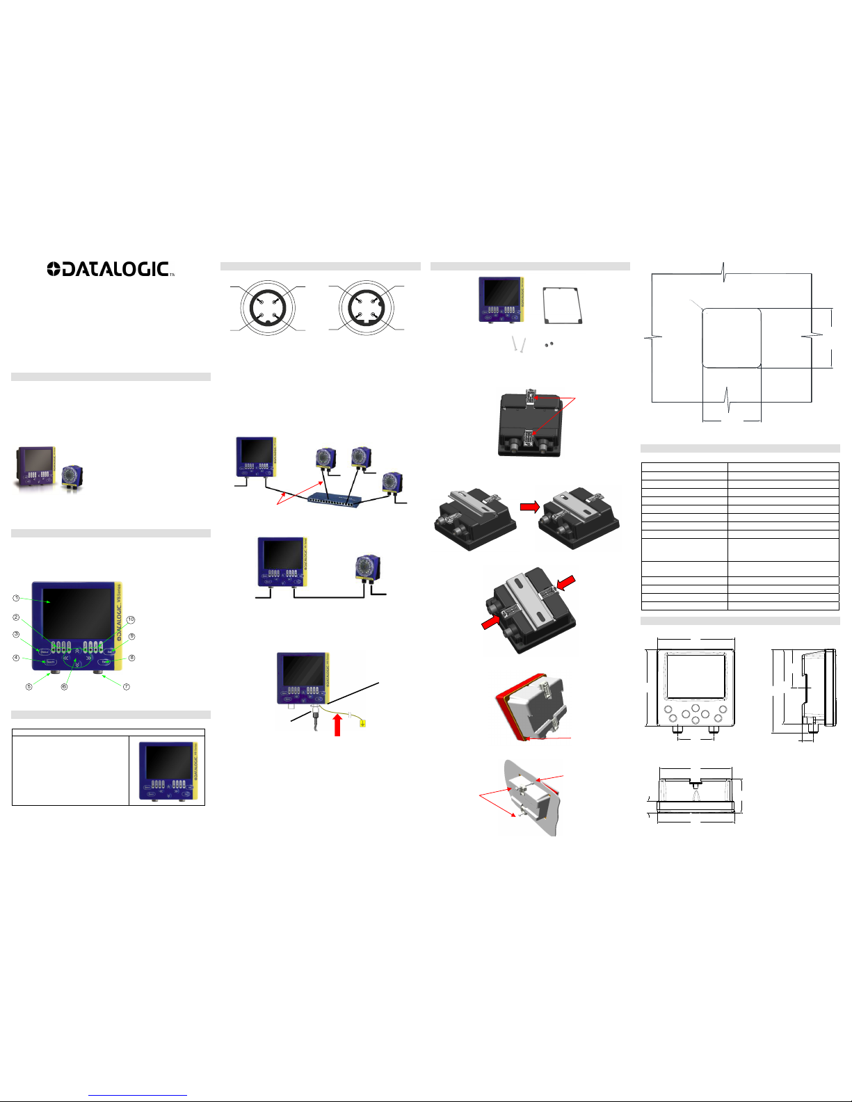
FEATURES
VSM MONITOR
The VSM displays the images processed by the DataVS2, manages
inspections and carries-out the parameter fine tuning.
1. Monitor
2. Status LEDs
3. STATUS Button
4. TEACH Button
5. Power Supply
Connector
6. ARROW Buttons
7. Ethernet Network
Connector
8. ESC Button
9. SET Button
10. Power, OUT, ETH
Link LEDs
SIGNALLING LEDS
From left to right
1. Setup Mode, green;
2. Adjust Mode, green;
3. Monitor Mode, green;
4. Main Menu, green;
5. Power Supply, green;
6. Digital Output 1, yellow;
7. Digital Output 2, yellow;
8. Connection Status, green.
1 2 3 4 5 6 7 8
ELECTRICAL CONNECTIONS
3
1
2
4
3
1
2
4
M12 4-Pin Male
(Power Supply)
pin 1: +24 Vdc
pin 2: Reserved
pin 3: GROUND
pin 4: Reserved
M12 Reverse Keyed 4-Pin Male
(Ethernet Network)
pin 1: Ethernet RX+
pin 2: Ethernet TX+
pin 3: Ethernet RX-
pin 4: Ethernet TX-
The VSM monitor can be connected in a LAN network using a straight
Ethernet cable or can be connected using a point to point connection directly
to a vision sensor.
LAN CONNECTION
POINT-TO-POINT CONNECTION
GROUND CONNECTION
To comply with the EMC requirements, the Ethernet cable shield has to be
grounded. (Use the yellow/green cable supplied with the VSM).
Insert the washer M12 on the yellow/green cable in the VSM connector and
then screw the Ethernet cable until the ring nut reaches the washer.
Warnings
Insert the cable into the correct connector following the key
indications inside the body
After inserting the cable, turn the ring nut anticlockwise to ensure
connection
Never force the cable inside the connectors.
Make sure that every cable is connected to the right connector
Before disconnecting the cable, completely turn the ring nut
anticlockwise
VSM MOUNTING
All the accessories for VSM mounting are included in the package. The VSM
unit can be installed on a DIN rail or on a panel.
DIN RAIL MOUNTING
Wedge the VSM unit in the DIN rail. First set the upper part of the monitor and
then press down the lower part.
Once inserted, block the VSM monitor using the two white side locking clips.
PANEL MOUNTING
Place the rubber seal around the monitor body.
Then fix the monitor on the panel using the two locking screws and the two
rubber caps.
92
±0.2
[3.62
±0.01
]
92
±0.2
[3.62
±0.01
]
R7.5
[R0.30]
Panel Cutout
TECHNICAL DATA
Supply Voltage: 24 Vdc ± 10%
Ripple Voltage: 2.4 Vpp max
Current Draw: Max 150 mA @ 24 Vdc
Dimensions: 96 x 96 x 39 mm
Indicators: 8 LEDs + 3.5’’ LCD color display
Setup: DataVS2 GUI
Data Retention: non volatile FLASH memory
Operating Temperature: -10 °C … +55 °C
Storage Temperature: -20 °C … +70 °C
Vibrations:
(EN60068-2-6)
14 mm @ 2 to 10 Hz;
1.5 mm @ 13 to 55 Hz;
2 g @ 70 to 200 Hz; 2 hours on each axis
Shock Resistance:
(EN60068-2-27)
11 ms (30 G) 6 shocks on each axis
Housing Material: ABS
Mechanical Protection: IP20 (IP40 when panel mounted)
Connections: 2 x M12 4-pin
Weight: 180 g
OVERALL DIMENSIONS
96
[3.78]
96
[3.78]
48.0
[1.89]
93.4
[3.68]
104
[4.09]
45.0
[1.77]
90.2
[3.55]
14.5
[0.57]
96
[3.78]
42.5
[1.67]
14.0
[0.55]
Locking Clips
Locking
Screws
Cap
Rubber Seal
LAN
Power
Powe
r
DATAVS-CV-RJ45D-03
Power
Power
Power
DATAVS-CV-VSM-xx
Powe
r
Washer M12
Ring Nut
Page 2
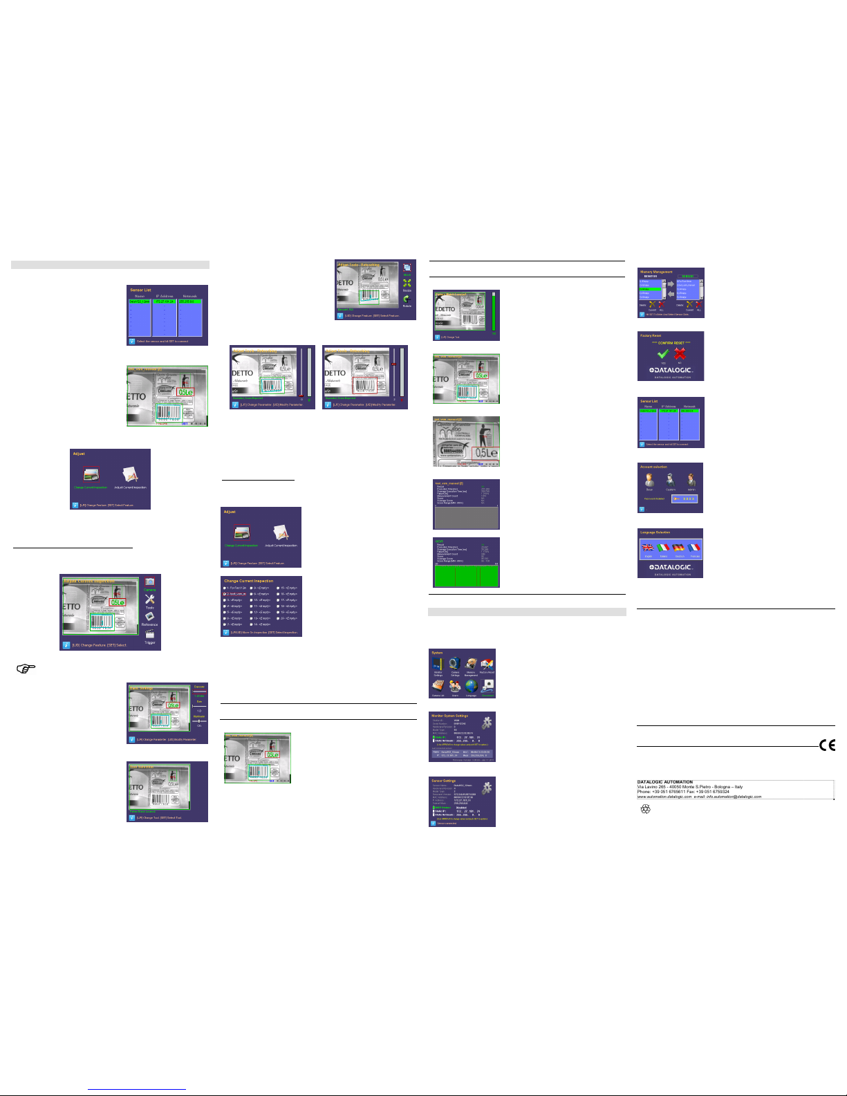
DEVICE USE
CONNECTION TO DATAVS2
To connect the VSM to DataVS2, just
select the sensor from the list displayed in
the “Net discovering” function.
Use the ARROW buttons to select the
sensor and press SET to confirm the
selection. If no devices have been found in
the first discovery, a new search can be
made by pressing TEACH.
ADJUST MODE
Once connected the desired DataVS2, the
VSM enters in the MONITOR mode and
the current inspection is displayed together
with the results of the relative tools.
By pressing TEACH, the VSM will display the following panel:
At this point the user can choose to change the current inspection or modify
the parameters.
Change of the Sensor Parameters and Tools
Selecting “Adjust Current Inspection” the user accesses the main panel of the
Adjust status:
Only the parameters that have been previously enabled by the
GUI as “Adjustable”, can be displayed and changed.
By selecting “Camera”, the user can
access the parameters that adjust the
brightness of the acquired image,
exposure time, gain and operating mode of
the illuminator.
By selecting “Tools”, the user can access
the panel shown in the figure, and select
the tools, on which changes are to be
carried-out, using the arrows.
Press SET to select the tool.
Once selected the tool, the user can scroll
the panels relevant to the different
parameters enabled as “Adjustable” using
the ARROWS (right and left).
The user can choose to move, resize or
rotate the ROI by using the ARROW
buttons (Up, Down) in the specific ROI
adjustment panel. The adjustment can be
carried-out using the 4 ARROW buttons
once selected the operation by pressing
SET.
In panels that allow the change of the other parameters, the new value can be
selected by moving the slider shown on the right side of the display. In order
to correctly adjust parameters, these panels display the current inspection
result relevant to the new configuration.
The ROI contour and the result bar become green if the result is positive and
red if negative.
Current Inspection Change
The following panel is displayed by pressing TEACH always from the monitor
status:
By selecting “Change Current Inspection”
the user can access another panel where
the inspection to carry-out can be selected.
The inspection can be changed by simply
pressing SET on the name of the desired
inspection.
At this point DataVS2 carries-out the new
inspection and the monitor status is
restored.
INSPECTION MONITORING AND SAVING
The monitor mode allows the user to control the result of the configured
inspection. Different visualisations modes are available that can be recalled
using the ARROW buttons. The SET button, instead, activates the statistics
panel.
Monitor Mode
To Activate
Press
View
Standard
Active by default
- Acquired image
- Tool used
- Result
Monitor Mode
To Activate
Press
View
Tool Result
DOWN ARROW
- Tool result
Display on Condition
ESC BUTTON
- Acquired image
- Tool used
Zoom
UP ARROW
- Acquired image
(with 200% zoom)
- Tool used
- Result
Statistics
SET BUTTON
- Inspection result
- Execution time
- Inspections carried-out
- Failure rate (%)
- Score
- Average score
- MIN-MAX score
NOTE: The statistics of
the single tools can be
displayed by pressing
STATUS.
MAIN SCREEN DESCRIPTION
The “System” panel is the main menu of the VSM unit and it allows the
access to all the other panels and the relative functions available.
System
Press STATUS from Monitor mode to access
the “System” panel.
When the VSM is already connected to
DataVS2, the “Disconnect” icon is displayed.
To disconnect DataVS2, the icon has to be
selected and SET pressed.
Monitor System Settings
This panel displays all the information relevant
to the VSM unit such as name, serial number,
model Firmware version, etc…
This panel allows changing the network
parameters such as IP Address and NetMask.
The data relevant to the last sensor connected
are displayed on the bottom.
Sensor Settings
This panel is used to change the network
parameters, when the VSM is connected to a
DataVS2.
Memory Management
The control of the memory slots is divided in two
parts: the “Monitor” section manages the VSM
memory slots while the Sensor” section
manages the memory slots of the DataVS2. The
slots can be cancelled and/or exchanged
between the two devices.
Factory Reset
The reset of the default settings of the VSM is
possible. All the memory slots are going to be
cancelled, the network parameters changed
and passwords cancelled.
Sensor List
Once carried-out a “Net discovery”, the list of
DataVS2 devices present in the subnet
connected to the VSM, is displayed.
To connect the desired sensor, the user has to
simply select it from the list and press SET.
Account Selection
The user typology can be changed in this panel.
To proceed with the changes, the user has to
simply digit the password relevant to the new
typology.
Language
The “Language” panel allows to change the
language system of the device.
COMPLIANCE
Only connect Ethernet and dataport connections to a network which has routing only within the plant or
building and no routing outside the plant or building.
CE COMPLIANCE
Warning: This is a Class A product. In a domestic environment this product may cause radio
interference in which case the user may be required to take adequate measures.
FCC COMPLIANCE
Modifications or changes to this equipment without the expressed written approval of Datalogic could
void the authority to use the equipment.
This device complies with PART 15 of the FCC Rules. Operation is subject to the following two
conditions: (1) This device may not cause harmful interference, and (2) this device must accept any
interference received, including interference which may cause undesired operation.
This equipment has been tested and found to comply with the limits for a Class A digital device,
pursuant to part 15 of the FCC Rules. These limits are designed to provide reasonable protection
against harmful interference when the equipment is operated in a commercial environment. This
equipment generates, uses, and can radiate radio frequency energy and, if not installed and used in
accordance with the instruction manual, may cause harmful interference to radio communications.
Operation of this equipment in a residential area is likely to cause harmful interference in which case the
user will be required to correct the interference at his own expense.
DECLARATION OF CONFORMITY
We DATALOGIC AUTOMATION declare under our sole responsibility that these products are conform
to the 2004/108/CE and successive amendments.
WARRANTY
DATALOGIC AUTOMATION warrants its products to be free from defects.
DATALOGIC AUTOMATION will repair or replace, free of charge, any product found to be faulty
during the warranty period of 36 months from the manufacturing date.
This warranty does not cover damage or liability deriving from the improper application of DATALOGIC
products.
DATALOGIC AUTOMATION
V
ia Lavino 265 - 40050 Monte S.Pietro - Bologna – Italy
Phone: +39 051 6765611 Fax: +39 051 6759324
www.automation.datalogic.com e-mail: info.automation@datalogic.com
DATALOGIC AUTOMATION for the environment: 100% recycled paper.
DATALOGIC AUTOMATION reserves the right to make changes or im provements to products at any time without
prior notice.
Datalogic and the Datalogic logo are registered trademarks of Datalogic S.p.A. in many countries,
including the U.S.A. and the E.U.
826000141 Rev.A © Copyright Datalogic 2011
 Loading...