

Page 1

PowerScan™ M8500
Industrial Handheld Area Imager Bar Code Reader
with Datalogic’s STAR Cordless System
™
Product Reference Guide
Page 2

Datalogic Scanning, Inc.
959 Terry Street
Eugene, Oregon 97402
USA
Telephone: (541) 683-5700
Fax: (541) 345-7140
ts of this documentation or the procedures described
An Unpublished Work - All rights reserved. No part of the conte
n
therein may be reproduced or transmitted in any form or by any means without prior written permission of Datalogic
Scanning, Inc. or its subsidiaries or affiliates ("Datalogic" or “Datalogic Scanning”). Owners of Datalogic products are hereby
granted a non-exclusive, revocable license to reproduce and transmit this documentation for the purchaser's own internal
business purposes. Purchaser shall not remove or alter any proprietary notices, including copyright notices, contained in
this documentation and shall ensure that all notices appear on any reproductions of the documentation.
u can acquire printed versions by contacting your Datalogic repre-
Should future revisions of this manual be published, y
o
sentative. Electronic versions may either be downloadable from the Datalogic website (www.scanning.datalogic.com) or
provided on
appropriate media. If you visit our website and would like to make comments or suggestions about this or
other Datalogic publications, please let us know via the "Contact Datalogic" page.
Disclaimer
o
Datalogic has taken reasonable measures t
provide information in this manual that is complete and accurate, however,
Datalogic reserves the right to change any specification at any time without prior notice.
Datalogic and the Datalogic logo are registered
trademarks of Datalogic S.p.A. in many countries, including the U.S.A and
the E.U. All other brand and product names referred to herein may be trademarks of their respective owners.
Microsoft Windows®, Windows® 2000, Windows®CE, Windows® NT, Windows® XP and the Windows logo are registered
ks of M
trademar
icrosoft Corporation.
Patents
This product is covered by one or more of the following patents:
Design Pat. AU 310201; AU 310202; CN 693980; CN 735959; HK 0602013.5M001; HK 0602013.5M002; JP 1305693;
KR 30-0460940; US D570,843 S.
US Pat. 6,478,226 B2; 6,512,218 B1; 6,808,114 B1; 6,877,664 B1; 6,997,385 B2; 7,053,954 B1; 7,102,116 B2;
7,282,688 B2; 7,387,246.
European Pat. 996,284 B1; 999,514 B1; 1,128,315 B1; 1,396,811 B1.
Additional patents pending.
Page 3

Table of Contents
Preface ........................................................................................................................................................... 7
About this Guide ....................................................................................................................................................................................................................7
Manual Overview ...................................................................................................................................................................................................................7
Manual Conventions ............................................................................................................................................................................................................8
References ................................................................................................................................................................................................................................ 8
Service and Support .............................................................................................................................................................................................................8
PRODUCTS ......................................................................................................................................................................................................8
SERVICE & SUPPORT .................................................................................................................................................................................... 8
CONTACT US .................................................................................................................................................................................................. 8
Compliance .............................................................................................................................................................................................................................. 9
Aiming System.............................................................................................................................................................................................................. 9
Power Supply ...............................................................................................................................................................................................12
WEEE Compliance ......................................................................................................................................................................................13
Introduction................................................................................................................................................. 15
Overview .................................................................................................................................................................................................................................15
General View .........................................................................................................................................................................................................................16
Powerscan® M8500 Readers .................................................................................................................................................................................. 16
BC-80X0 / C-8000 CRADLES ................................................................................................................................................................................... 17
Using the Reader .................................................................................................................................................................................................................18
Aiming System............................................................................................................................................................................................................ 18
Normal Operation...................................................................................................................................................................................................... 19
Configuration Methods .....................................................................................................................................................................................................19
Reading Configuration Codes ...............................................................................................................................................................19
Using Datalogic Aladdin™ ......................................................................................................................................................................19
Sending Configuration Strings from Host ........................................................................................................................................19
Autoscanning ........................................................................................................................................................................................................................20
Normal Mode............................................................................................................................................................................................................... 20
Pattern Mode............................................................................................................................................................................................................... 20
Camera Control ....................................................................................................................................................................................................................20
Defining Data Formatting ................................................................................................................................................................................................21
Concatenation ............................................................................................................................................................................................................ 22
PowerScan M8500 Setup............................................................................................................................ 23
Package Contents...................................................................................................................................................................................................... 23
Installation .............................................................................................................................................................................................................................23
BC-80X0 Interface Cable Connections ............................................................................................................................................................... 23
RS-232 Connection ....................................................................................................................................................................................24
USB ...................................................................................................................................................................................................................24
IBM USB POS ................................................................................................................................................................................................24
WEDGE Connection ...................................................................................................................................................................................25
PEN Emulation Connection ....................................................................................................................................................................25
Network Connections ........................................................................................................................................................................................................26
BC-8060 Network Connectors............................................................................................................................................................................... 26
Network Cabling ........................................................................................................................................................................................................ 26
Network Termination ............................................................................................................................................................................................... 27
PowerScan® M8500 Battery Maintenance ..................................................................................................................................................................28
Battery Charging........................................................................................................................................................................................................ 28
Replacing PowerScan® M8500 Batteries ........................................................................................................................................................... 28
Mounting The BC-80X0 / C-8000 Cradle............................................................................................................................................................ 30
Desktop Mounting .................................................................................................................................................................................................... 31
Portable Desktop Use ...............................................................................................................................................................................31
Fixed Desktop Use .....................................................................................................................................................................................32
Wall Mounting .............................................................................................................................................................................................33
System and Network Layouts .........................................................................................................................................................................................35
Stand-Alone Layouts ................................................................................................................................................................................................ 35
Product Reference Guide
1
Page 4

Contents
Multiple Stand-Alone Layouts............................................................................................................................................................................... 36
Multidrop STAR-System™ Network Layouts..................................................................................................................................................... 37
Host Master Layout ...................................................................................................................................................................................37
BC-8060 Master Layout ............................................................................................................................................................................38
Master BC-8060 Network Troubleshooting .....................................................................................................................................38
Setup Procedures ................................................................................................................................................................................................................39
PowerScan® M8500/BC-80X0 Point-to-Point Setup...................................................................................................................................... 39
PowerScan® M8500/BC-80X0 Stand-Alone Setup ......................................................................................................................................... 40
Using Multiple M-Series Readers with Same Cradle .....................................................................................................................42
PowerScan® M8500/STAR-Modem™ in Stand-Alone Mode .....................................................................................................42
PowerScan® M8500/STAR-System™ Setup....................................................................................................................................................... 43
BC-8060 STAR-System™ Network Setup............................................................................................................................................................ 45
Interface Selection ..............................................................................................................................................................................................................47
RS-232.......................................................................................................................................................................................................................................47
POS Terminals ............................................................................................................................................................................................................. 47
PEN.............................................................................................................................................................................................................................................47
WEDGE......................................................................................................................................................................................................................................48
IBM Terminals 31xx, 32xx, 34xx, 37xx: ................................................................................................................................................................ 48
KEY TRANSMISSION MODE..................................................................................................................................................................................... 48
ALT MODE..................................................................................................................................................................................................................... 49
WYSE TERMINALS .................................................................................................................................................................................................................49
KEYBOARD TYPE......................................................................................................................................................................................................... 49
DIGITAL TERMINALS ...........................................................................................................................................................................................................50
USB Configuration..................................................................................................................................................................................................... 50
USB Start-up .................................................................................................................................................................................................50
Configuration Using Code Symbols........................................................................................................... 53
Configuration Parameters ...................................................................................................................................................................................... 53
Reading Configuration Barcodes ......................................................................................................................................................................... 54
RS-232 PARAMETERS ..........................................................................................................................................................................................................55
Baud Rate...................................................................................................................................................................................................................... 56
Parity............................................................................................................................................................................................................................... 56
Data Bits ........................................................................................................................................................................................................................ 57
Stop Bits ........................................................................................................................................................................................................................ 57
Handshaking................................................................................................................................................................................................................ 57
ACK/NACK Protocol................................................................................................................................................................................................... 58
FIFO................................................................................................................................................................................................................................. 58
Inter-character Delay................................................................................................................................................................................................ 58
RX Timeout................................................................................................................................................................................................................... 59
Serial Trigger Lock ..................................................................................................................................................................................................... 59
USB PARAMETERS ................................................................................................................................................................................................................60
USB-COM ............................................................................................................................................................................................................................61
Handshaking................................................................................................................................................................................................................ 61
ACK/NACK Protocol................................................................................................................................................................................................... 61
FIFO................................................................................................................................................................................................................................. 61
Inter-character Delay................................................................................................................................................................................................ 62
RX Timeout................................................................................................................................................................................................................... 62
Serial Trigger Lock ..................................................................................................................................................................................................... 63
USB-KBD ..............................................................................................................................................................................................................................64
Keyboard Nationality................................................................................................................................................................................................ 64
FIFO................................................................................................................................................................................................................................. 65
Inter-character Delay................................................................................................................................................................................................ 66
Inter-code Delay......................................................................................................................................................................................................... 66
USB Keyboard Speed................................................................................................................................................................................................ 66
WEDGE PARAMETERS ........................................................................................................................................................................................................67
Keyboard Nationality................................................................................................................................................................................................ 68
Caps Lock...................................................................................................................................................................................................................... 69
Caps Lock Auto-Recognition (IBM AT compatible only).............................................................................................................................. 70
Num Lock...................................................................................................................................................................................................................... 70
Inter-character Delay................................................................................................................................................................................................ 70
Inter-code Delay......................................................................................................................................................................................................... 71
Keyboard Setting ....................................................................................................................................................................................................... 71
2
PowerScan® M8500
Page 5

Contents
Control Character Emulation................................................................................................................................................................................. 73
PEN EMULATION ..................................................................................................................................................................................................................74
Operating Mode......................................................................................................................................................................................................... 75
Minimum Output Pulse ........................................................................................................................................................................................... 76
Conversion to Code 39 ............................................................................................................................................................................................ 76
Conversion to Code 128.......................................................................................................................................................................................... 77
Overflow........................................................................................................................................................................................................................ 77
Output Level................................................................................................................................................................................................................ 77
Idle Level ....................................................................................................................................................................................................................... 78
Inter-Block Delay........................................................................................................................................................................................................ 78
NETWORK PARAMETERS ...................................................................................................................................................................................................79
RS-485 Network.......................................................................................................................................................................................................... 80
Network Baud Rate.................................................................................................................................................................................................... 80
Slave Address Range................................................................................................................................................................................................. 81
Network Warning Message .................................................................................................................................................................................... 81
Reception Warning Message................................................................................................................................................................................. 81
Master Cradle Header............................................................................................................................................................................................... 82
Master Cradle Terminator....................................................................................................................................................................................... 83
DATA FORMAT ......................................................................................................................................................................................................................84
Code Identifier ............................................................................................................................................................................................................ 85
Custom Code Identifier............................................................................................................................................................................................ 86
Header............................................................................................................................................................................................................................ 89
Terminator.................................................................................................................................................................................................................... 90
Code Length Tx .......................................................................................................................................................................................................... 91
Address Stamping ..................................................................................................................................................................................................... 91
Address Delimiter ..................................................................................................................................................................................................... 92
Time Stamping .......................................................................................................................................................................................................... 92
Time Stamping Delimiter........................................................................................................................................................................................ 93
Symbology Dependent Parameters .........................................................................................................................................................................94
Symbology Specific Format ................................................................................................................................................................................... 95
Symbology Headers.................................................................................................................................................................................................. 95
Headers.......................................................................................................................................................................................................................... 96
Symbology Terminators.......................................................................................................................................................................................... 96
Terminators.................................................................................................................................................................................................................. 96
Symbology Character Substitution..................................................................................................................................................................... 97
Character Substitution............................................................................................................................................................................................. 97
Symbology Character Deletion ............................................................................................................................................................................ 97
Character Deletion .................................................................................................................................................................................................... 98
Symbology Specific Format Default ................................................................................................................................................................... 98
Concatenation ..................................................................................................................................................................................................................99
Define Concatenation .............................................................................................................................................................................................. 99
Concatenation Enable/Disable ............................................................................................................................................................................. 99
Concatenation Length ...................................................................................................................................................................................................99
First Concatenated Code Length ......................................................................................................................................................................... 99
Second Concatenated Code Length................................................................................................................................................................... 99
Third Concatenated Code Length .................................................................................................................................................................... 100
Fourth Concatenated Code Length ................................................................................................................................................................. 100
Concatenation with Intercode Delay............................................................................................................................................................... 100
Concatenation Failure Transmission ............................................................................................................................................................... 100
Concatenation Timeout ..........................................................................................................
smission After T
Tran
Concatenation Result Code ID........................................................................................................................................................................... 101
CAMERA CONTROL ..........................................................................................................................................................................................................102
Exposure Mode........................................................................................................................................................................................................ 102
AIMING SYSTEM ................................................................................................................................................................................................................103
Good Read Spot ...................................................................................................................................................................................................... 103
CODE SELECTION .............................................................................................................................................................................................................104
Issue Identical Codes ............................................................................................................................................................................................. 104
Linear Symbologies .....................................................................................................................................................................................................105
UPC/EAN/JAN Family............................................................................................................................................................................................. 105
Code 39 Family ........................................................................................................................................................................................................ 106
imeout................................................................................................................................................................................ 101
............................................................................. 100
Product Reference Guide
3
Page 6

Contents
Code 32 Family ........................................................................................................................................................................................................ 107
Interleaved 2 of 5 Family...................................................................................................................................................................................... 107
Codabar Family........................................................................................................................................................................................................ 108
Code 128 Family...................................................................................................................................................................................................... 109
Code 93 Family ........................................................................................................................................................................................................ 110
GS1 Databar™ Family............................................................................................................................................................................................. 111
2D Symbologies ............................................................................................................................................................................................................ 112
PDF417........................................................................................................................................................................................................................ 112
Micro PDF417 ........................................................................................................................................................................................................... 113
DataMatrix Family................................................................................................................................................................................................... 113
QR Family................................................................................................................................................................................................................... 113
Micro QR..................................................................................................................................................................................................................... 114
Postal Codes Family ............................................................................................................................................................................................... 114
Australian Table Selection ................................................................................................................................................................................... 115
Intelligent Mail Barcode ....................................................................................................................................................................................... 115
Maxicode Family ..................................................................................................................................................................................................... 115
Aztec............................................................................................................................................................................................................................ 116
Composite Codes.................................................................................................................................................................................................... 116
READING PARAMETERS .................................................................................................................................................................................................. 117
Trigger Mode............................................................................................................................................................................................................ 118
Trigger Type.............................................................................................................................................................................................................. 118
Flash Mode................................................................................................................................................................................................................ 118
Beeper Tone.............................................................................................................................................................................................................. 118
Beeper Volume ........................................................................................................................................................................................................ 119
Beeper Duration ...................................................................................................................................................................................................... 119
Reads per Cycle........................................................................................................................................................................................................ 119
Scan Timeout............................................................................................................................................................................................................ 119
User Defined Beeper ................................................................................................................................................................................................... 120
User Defined Beeper Tone................................................................................................................................................................................... 120
User Defined Beeper Volume ............................................................................................................................................................................. 120
User Defined Beeper Duration........................................................................................................................................................................... 120
Test User Defined Beeper .................................................................................................................................................................................... 120
Code Ordering and Selection ................................................................................................................................................................................... 121
Codes per Scan ........................................................................................................................................................................................................ 121
Central Code Transmission.................................................................................................................................................................................. 121
Order By Code Length........................................................................................................................................................................................... 121
Order By Code Symbology .................................................................................................................................................................................. 121
Autoscan .......................................................................................................................................................................................................................... 122
Autoscan Mode ....................................................................................................................................................................................................... 122
Autoscan Aiming System..................................................................................................................................................................................... 122
Autoscan Hardware Trigger................................................................................................................................................................................ 122
Autoscan Illumination System ........................................................................................................................................................................... 122
Safety Time................................................................................................................................................................................................................ 123
Safety Time Duration............................................................................................................................................................................................. 123
RADIO PARAMETERS .......................................................................................................................................................................................................124
Radio Protocol Timeout........................................................................................................................................................................................ 125
Radio RX Timeout ................................................................................................................................................................................................... 125
Power-Off Timeout..............................................................................................................
der Shut-Down .........
Rea
Transmission Mode ................................................................................................................................................................................................ 126
Beeper Control for Radio Response ................................................................................................................................................................. 127
Single Store............................................................................................................................................................................................................... 128
Batch Mode............................................................................................................................................................................................................... 129
Find Me....................................................................................................................................................................................................................... 129
DISPLAY and KEYPAD PARAMETERS .........................................................................................................................................................................130
DISPLAY PARAMETERS ............................................................................................................................................................................................... 131
Date and Time.......................................................................................................................................................................................................... 131
Contrast...................................................................................................................................................................................................................... 131
Font Size..................................................................................................................................................................................................................... 131
Backlight .................................................................................................................................................................................................................... 132
Display-Off Timeout............................................................................................................................................................................................... 132
........................................................................................................................................................................................ 126
................................................................................... 126
4
PowerScan® M8500
Page 7

Contents
Display Mode............................................................................................................................................................................................................ 132
KEYPAD PARAMETERS ................................................................................................................................................................................................133
Keypad........................................................................................................................................................................................................................ 133
Advanced Data Formatting...................................................................................................................... 135
Format Definition .............................................................................................................................................................................................................136
Method 1 - Extracting Information from Barcode ...................................................................................................................... 137
Method 2 - Manipulating the Barcode Data .................................................................................................................................142
Match Conditions .............................................................................................................................................................................................................151
Format Enable/Disable ................................................................................................................................................................................................... 152
Mismatch Result ................................................................................................................................................................................................................153
References ................................................................................................................................................. 155
RS-232 Parameters ...........................................................................................................................................................................................................155
Handshaking............................................................................................................................................................................................................. 155
ACK/NACK Protocol................................................................................................................................................................................................ 156
PowerScan® M8500 Readers ............................................................................................................................................................... 156
FIFO.............................................................................................................................................................................................................................. 156
PowerScan® M8500 Readers ............................................................................................................................................................... 156
RX Timeout................................................................................................................................................................................................................ 157
Pen Parameters .................................................................................................................................................................................................................157
Minimum Output Pulse ........................................................................................................................................................................................ 157
Conversion to Code 39 and Code 128............................................................................................................................................................. 157
PowerScan® M8500 Series Readers ..................................................................................................................................................157
Overflow..................................................................................................................................................................................................................... 157
Output and Idle Levels.......................................................................................................................................................................................... 158
Inter-Block Delay..................................................................................................................................................................................................... 158
Network Parameters ........................................................................................................................................................................................................ 158
Slave Address Range First/Last .......................................................................................................................................................................... 158
Network Warning Message ................................................................................................................................................................................. 159
Reception Warning Message.............................................................................................................................................................................. 159
Master Header/Terminator Selection .............................................................................................................................................................. 159
Data Format ........................................................................................................................................................................................................................ 160
Header/Terminator Selection............................................................................................................................................................................. 160
Define Special Key Sequence ............................................................................................................................................................................. 161
Address Stamping .................................................................................................................................................................................................. 168
Address Delimiter ................................................................................................................................................................................................... 168
Time Stamping Format......................................................................................................................................................................................... 168
Time Stamping Delimiter..................................................................................................................................................................................... 168
Reading Parameters ........................................................................................................................................................................................................168
Trigger Signal ........................................................................................................................................................................................................... 168
Reads per Cycle........................................................................................................................................................................................................ 168
Safety Time................................................................................................................................................................................................................ 169
Configuration Editing Commands.................................................................................................................................................................... 169
Radio Parameters ............................................................................................................................................................................................................. 170
Radio Protocol Timeout........................................................................................................................................................................................ 170
Radio RX Timeout ................................................................................................................................................................................................... 170
Power-Off Timeout................................................................................................................................................................................................. 170
Transmission Mode ................................................................................................................................................................................................ 171
Beeper Control for Radio Response ................................................................................................................................................................. 171
Single Store............................................................................................................................................................................................................... 171
Batch Mode............................................................................................................................................................................................................... 172
Find Me....................................................................................................................................................................................................................... 172
Display Parameters .........................................................................................................................................................................................................173
Display Mode............................................................................................................................................................................................................ 173
Default Parameters for POS Terminals ...................................................................................................................................................................... 174
Message Formatting................................................................................................................................. 175
Standard Message Formatting ....................................................................................................................................................................................175
Messages from Host to Reader .................................................................................................................................................................................... 175
Cursor Control.......................................................................................................................................................................................................... 176
Font Selection .......................................................................................................................................................................................................... 177
Clearing Display....................................................................................................................................................................................................... 177
Product Reference Guide
5
Page 8

Contents
LED and Beeper Control ....................................................................................................................................................................................... 177
Setting RTC................................................................................................................................................................................................................ 177
Messages from SCANNER Command Keys .............................................................................................................................................................. 178
PowerScan M8500 Keypad.................................................................................................................................................................................. 178
Technical Features .................................................................................................................................... 179
Technical Features ...........................................................................................................................................................................................................179
BC-80X0 / C-8000 .................................................................................................................................................................................................... 184
System and Radio Features................................................................................................................................................................................. 185
Indicators ............................................................................................................................................................................................................................. 186
PowerScan® M8500 LED Indicators.................................................................................................................................................................. 186
Beeper .........................................................................................................................................................................................................186
Good Read Spot .......................................................................................................................................................................................187
Default Settings ................................................................................................................................................................................................................. 189
Host Configuration Strings....................................................................................................................... 193
Serial Configuration Strings .......................................................................................................................................................................................... 194
Programming for Expert Users................................................................................................................ 209
Function Description ............................................................................................................................................................................. 209
FindStringByStarting&EndingChar (FSTR) .....................................................................................................................................210
FindStringByStartingChar&Len (FLSTR) ..........................................................................................................................................210
SelectString (SSTR) ..................................................................................................................................................................................210
FindPosition (FPOS) ................................................................................................................................................................................211
StringLength (LSTR) ............................................................................................................................................................................... 211
StringConcatenation ..............................................................................................................................................................................211
StringDiscard ............................................................................................................................................................................................ 211
InsertString (ISTR) ....................................................................................................................................................................................211
ReplaceString (RSTR) ..............................................................................................................................................................................211
Using Format Output in Format Definition ................................................................................................................................... 212
Code Identifier Table ................................................................................................................................ 213
Sample Barcodes....................................................................................................................................... 215
Test Code Symbols ................................................................................................................................................................................. 215
Hex & Numeric Table................................................................................................................................. 217
Hex Numeric Table ........................................................................................................................................................................................................... 219
Autoscan Pattern Code .................................................................................................................................................................................................. 222
6
PowerScan® M8500
Page 9

About this Guide
This Product Reference Guide (PRG) is provided for users seeking advanced technical
information, including connection, programming, maintenance and specifications. The
Quick Reference Guide (QRG) and other publications associated with this product are
downloadable free of charge from the website listed on the back cover of this manual.
Typically, units are factory-programmed for the most common terminal and communications
settings. If
accomplished by scanning the programming barcodes within this guide.
Preface
you need to modify any programmable settings, custom configuration can be
Programming can alternatively be performed using the Data
application which is downloadable from the Datalogic website listed on the back cover of this
manual. This multi-platform utility program allows device configuration using a PC. It
communicates to the device using a serial or USB cable and can also create configuration
barcodes to print.
Manual Overview
Chapter 1, Introduction gives an general description of the product.
Chapter 2, PowerScan M8500 Setup provides information needed to get the device up and
running.
Chapter 3, Configuration Using Code Symbols defines options for all symbologies and
provides programming barcodes necessary for configuring these features.
Chapter 4, Advanced Data Formatting, provides information about advanced formatting
parameters.
Chapter 5, References gives additional, more detailed information for some complex
parameters.
Chapter 6, Message Formatting explains the communication format between the reader
and the host.
Appendix
environmental and regulatory specifications and functions and behaviors of the reader’
and Beeper indicators.
A, Technical Features lists physical and performance characteristics, as well as
logic Aladdin™ Configuration
s LED
Appendix
configuration using serial strings sent from the host.
Appendix
users who want to define a personalized code formatting.
Appendix
Appendix
functioning.
Appendix F, Hex & Numeric Table includes numeric barcodes to be scanned for certain
parameter settings.
B, Host Configuration Strings provides a description of how to modify the device
C, Programming for Expert Users describes programming language for expert
D, Code Identifier Table lists Code IDs for various symbologies.
E, Sample Barcodes provides test code symbols allowing you to check the reader’s
Product Reference Guide 7
Page 10

Preface
Manual Conventions
The following conventions are used in this document:
The symbols listed below are used in this manual to notify the reader of key issues or
procedures that must be
CAUTION
WAR NI NG
observed when using the reader:
Notes contain information necessary for properly diagnosing, repairing
and operating the reader.
The CAUTION symbol advises you of actions that could damage equipment or
A WARNING symbol calls attention to actions that could result in personal injury.
property.
References
Current versions of the Product Reference Guide (PRG), Quick Reference Guide (QRG),
Datalogic Aladdin™ Configuration application, and any other manuals, instruction sheets
and utilities for this product can be downloaded from the website listed on the back cover of
this manual. Alternatively, printed copies or product support CDs can be purchased
through your Datalogic reseller.
Service and Support
Datalogic provides several services as well as technical support through its website. Log on to
www.scanning.datalogic.com and click on the links indicated for further information
including:
PRODUCTS
Search through the links to arrive at your product page where you can download specific
Manuals and Software & Utilities including:
• Datalogic Aladdin™ a multi-platform utility program that allows device configuration using a PC. It pro
barcode printing
vides RS-232 interface configuration as well as configuration
.
SERVICE & SUPPORT
• Technical Support - Product documentation and programming guides and Technical
Support Department in the world
• Service Programs - Warranty Extensions and Maintenance Agreements
• Repair Services - Flat Rate Repairs and Return M
• Downloads – Manuals & Documentation, Data Sheets, Prod
aterial Au
thorization (RMA) Repairs.
uct Catalogues, etc.
CONTACT US
Information Request Form and Sales & Service Network
8 PowerScan® M8500
Page 11
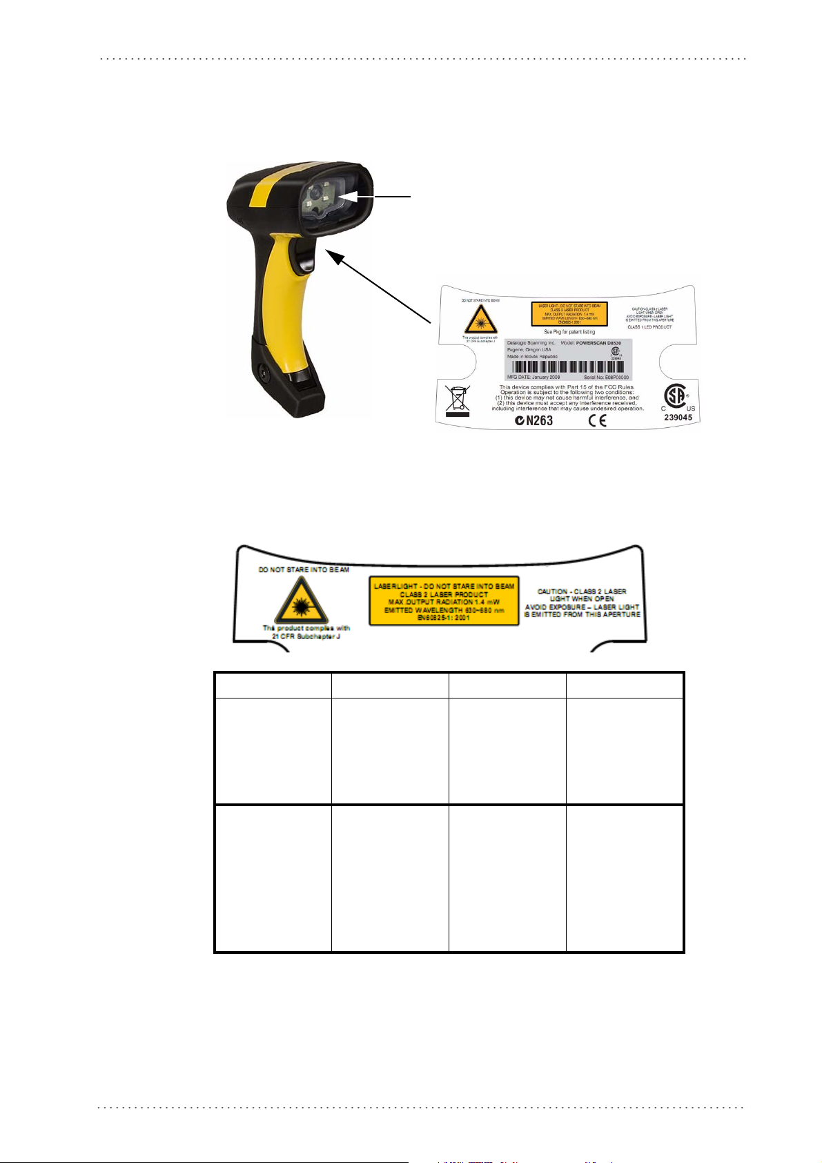
Compliance
Aiming System Imager Beam Output Window
Figure 1. POWERSCAN® PM8500 Reader Product Label
Compliance
Aiming System
The PowerScan® PM8500 aiming system meets the requirements for laser safety.
LA LUCE LASER È VISIBILE
ALL'OCCHIO UMANO E VIENE
EMESSA DALLA FINESTRA
INDICATA NELLA FIGURA.
LUCE LASER NON FISSARE IL
SC IO
FA
APP
ARECCHIO LASER DI
CLASSE 2 M
D'USCITA:
LUNGHEZZA D'ONDA EMESSA:
CONFORME A EN 60825-1
(2001)
I D F E
ASSIMA POTENZA
DIE LASER-STRAHLUNG IST
FÜR DAS MENSCHLICHE AU
SICHTBAR UND WIRD AM
STRAHLAUS-
TRITTSFENTSTER AUSGESENDET (SIEHE BILD)
LASERSTRAHL
DEN STRAHL
PRODUKT DER LASERKLASSE
2 M
TUNG:
WELLENLÄGE:
ENTSPR. EN 60825-1 (2001)
UNG NICHT IN
BLICKEN
AXIMALE AUSGANGSLEIS-
LE RAYON LASER EST VISIBLE
GE
'OEUIL NU ET IL EST ÉMI
À L
PAR LA FENÊTRE DÉSIGNÉE
SUR L'ILLUSTRATION DANS LA
FIGURE
RAYON LASER EVITER DE
RDER LE RAYON APPAR-
REGA
EIL LASER DE CLASSE 2 PUISSANCE DE SORTIE:
LONGUER D'ONDE EMISE:
CONFORME A EN 60825-1
(2001)
LA LUZ LÁSER ES VISIBLE AL
S
O HUMANO Y ES EM
OJ
POR LA VENTANA INDICADA
EN LA FIGURA.
LÁSER NO MIRAR FIJO
RAYO
AYO AP
EL R
CLASE 2 MÁXIMA POTENCIA
DE SALIDA:
LONGITUD DE ONDA EMITIDA:
CONFORME A EN 60825-1
(2001)
ITIDA
ARATO LÁSER DE
Product Reference Guide 9
Page 12

Preface
ENGLISH
The following information is provided to comply with the rules imposed by international
authorities and refers to the correct use of your terminal.
STANDARD LASER SAFETY REGULATIONS
This product conforms to the applicable requirements of both CDRH 21 CFR 1040 and
EN 60825-1 at the date of manufacture.
For installation, use and maintenance, it is not necessary to open the device.
Use of controls or adjustments or performance of procedures other than those
specified herein may result in exposure to hazardous visible laser light.
WAR NIN G
The product utilizes a low-power laser diode. Although staring directly at the laser beam
momentarily causes no known biological damage, avoid staring at the beam as one would
with any very strong light source, such as the sun. Avoid allowing the laser beam to hit the
eye of an observer, even through reflective surfaces such as mirrors, etc.
ITALIANO
Le seguenti informazioni vengono fornite dietro direttive delle autorità internazionali e si
riferiscono all’uso corretto del terminale.
NORMATIVE STANDARD PER LA SICUREZZA LASER
Questo prodotto risulta conforme alle normative vigenti sulla sicurezza laser alla data di
produzione: CDRH 21 CFR 1040 e EN 60825-1.
Non si rende mai necessario aprire l’appa-recchio per motivi di installazion
e, utilizzo o
manutenzione.
L'utilizzo di procedure o regolazioni differenti da quelle descritte
nella documentazione può provocare un'esposizione pericolosa a
luce laser visibile.
AT T EN Z I ON E
Il prodotto utilizza un diodo laser a bassa potenza. Sebbene non siano noti danni riportati
dall’occhio umano in seguito ad una esposizione di breve durata, evitare di fissare il raggio
laser così come si eviterebbe qualsiasi altra sorgente di luminosità intensa, ad esempio il sole.
Evitare inoltre di dirigere il raggio laser negli occhi di un osservatore, anche attraverso
superfici riflettenti come gli specchi.
DEUTSCH
Die folgenden Informationen stimmen mit den Sicherheitshinweisen überein, die von
internationalen Behörden auferlegt wurden, und sie beziehen sich auf den korrekten
Gebrauch vom Terminal.
NORM FÜR DIE LASERSICHERHEIT
Dies Produkt entspricht am Tag der Herstellung den gültigen EN 60825-1 und CDRH 21
CFR 1040 Normen für die Lasersicherheit.
10 PowerScan® M8500
Page 13

Compliance
Es ist nicht notwendig, das Gerät wegen Betrieb oder Installations-, und Wartungs-arbeiten
zu öffnen.
Jegliche Änderungen am Gerät sowie Vorgehensweisen, die nicht in
dieser Betriebsanleitung beschreiben werden, können ein gefährliches Laserlicht verursachen.
ACHTUNG
Der Produkt benutzt eine Laserdiode. Obwohl zur Zeit keine Augenschäden von kurzen
Einstrahlungen bekannt sind, sollten Sie es vermeiden für längere Zeit in den Laserstrahl zu
schauen, genauso wenig wie in starke Lichtquellen (z.B. die Sonne). Vermeiden Sie es, den
Laserstrahl weder gegen die Augen eines Beobachters, noch gegen reflektierende
Oberflächen zu richten.
FRANÇAIS
Les informations suivantes sont fournies selon les règles fixées par les autorités
internationales et se réfèrent à une correcte utilisation du terminal.
NORMES DE SECURITE LASER
Ce produit est conforme aux normes de sécurité laser en vigueur à sa date de fabrication:
CDRH 21 CFR 1040 et EN 60825-1.
Il n’est pas nécessaire d’ouvrir l’appareil pour l’installation, l’utilisation ou l’entretien.
L'utilisation de procédures ou réglages différents de ceux donnés
ici peut entr
ble.
aîner une danger
euse exposition à lumière laser visi-
AT T EN T I ON
Le produit utilise une diode laser. Aucun dommage aux yeux humains n’a été constaté à la
suite d’une exposition au rayon laser. Eviter de regarder fixement le rayon, comme toute
autre source lumineuse intense telle que le soleil. Eviter aussi de diriger le rayon vers les yeux
d’un observateur, même à travers des surfaces réfléchissantes (miroirs, par exemple).
ESPAÑOL
Las informaciones siguientes son presentadas en conformidad con las disposiciones de las
autoridades internacionales y se refieren al uso correcto del terminal.
NORMATIVAS ESTÁNDAR PARA LA SEGURIDAD LÁSER
Este aparato resulta conforme a las normativas vigentes de seguridad láser a la fecha de
producción: CDRH 21 CFR 1040 y EN 60825-1.
No es necesario abrir el aparato para la instalación, la utilización o la manutención.
Product Reference Guide 11
Page 14

Preface
La utilización de procedimientos o regulaciones diferentes de aquellas
describidas en la documentación puede causar una exposición peligrosa a la luz láser visible
.
AT EN C I ÓN
El aparato utiliza un diodo láser a baja potencia. No son notorios daños a los ojos humanos
a consecuencia de una exposición de corta duración. Eviten de mirar fijo el rayo láser así
como evitarían cualquiera otra fuente de luminosidad intensa, por ejemplo el sol. Además,
eviten de dirigir el rayo láser hacia los ojos de un observador, también a través de superficies
reflectantes como los espejos.
The POWERSCAN® PM8500 Hand-Held Reader is not userserviceable. Opening the case of the unit can cause internal damage
and will void the warranty.
CAUTION
Power Supply
This device is intended to be supplied by a UL Listed or CSA Certified Power Unit marked
"Class 2" or "LPS" output rated 5-30 V, minimum 0.75 A which supplies power directly to
the scanner via the jack connector on the cable.
12 PowerScan® M8500
Page 15

Compliance
WEEE Compliance
Waste Electrical and Electronic Equipment (WEEE) Statement
English
For information about the disposal of Waste Electrical and Electronic Equipment (WEEE),
please refer to the website at www.scanning.datalogic.com.
Italian
Per informazioni sullo smaltimento delle apparecchiature elettriche ed elettroniche
consultare il sito Web www.scanning.datalogic.com.
French
Pour toute information relative à l’élimination des déchets électroniques (WEEE), veuillez
consulter le site Internet www.scanning.datalogic.com.
German
Informationen zur Entsorgung von Elektro- und Elektronik- Altgeräten (WEEE) erhalten
Sie auf der Webseite www.scanning.datalogic.com.
Spanish
Si desea información acerca de los procedimientos para el desecho de los residuos del equipo
eléctrico y electrónico (WEEE), visite la página Web www.scanning.datalogic.com.
Portuguese
Para informações sobre a disposição de Sucatagem de Equipamentos Eléctricos e Eletrônicos
(WEEE - Waste Electrical and Electronic Equipment), consultar o site web
www.scanning.datalogic.com.
Chinese
有关处理废弃电气电子设备 (WEEE) 的信息, 请参考 Datalogic 公司的网站:
http://www.scanning.datalogic.com/。
Japanese
廃電気電子機器 (WEEE) の処理についての関連事項は Datalogic のサイト
www.scanning.datalogic.com, をご参照下さい。
Product Reference Guide 13
Page 16

Preface
NOTES
14 PowerScan® M8500
Page 17

Overview
Chapter 1
Introduction
The PowerScan® PM8500 cordless handheld Reader Family packs a lot of performance into
an attractive, rugged, handheld device. It operates in commercial and industrial environments
as well as the front office.
In all applications where mobility is a value, the PowerScan® PM8500 represents the key to
increase productivity and flexibility in the working area. PowerScan®
communicates through a low power, license free radio in the 433 MHz band (910 MHz for
USA version) and allows bi-directional communication between the base station and the host.
PowerScan® PM8500 also includes a display and a 3-key keypad. Thanks to these features,
the operator can receive information from the host, interact with the central system and
visualize the code read. The cordless system offers scalable solutions to solve simple
applications and complex projects:
• Point to point: each reader is associated with its own base station;
• Multipoint: up to 32 readers transmit data to one base station;
• Network: to cover a wide area, connecting u
ously working in automatic roaming.
PowerScan
band solution for mobile applications that provides the widest family of narrow band devices
on the market. In addition, the main feature of PowerScan PM8500 are:
Omni-directional
Operating
Decoding
and
Imaging
Flash Memory
USA Driver License
Parsing
®
PM8500 is 100% compatible with STAR-System™, the Datalogic RF narrow
To read a symbol, simply aim at the code and pull the trigger. Since
PowerScan® PM8500 is a powerful omni-directional reader, the
orientation of the symbol is not important.
Thanks to powerful algorithms, PowerScan® PM8500 reliably decodes
all major 1D (linear) barcodes, 2D stacked codes (such as PDF417), 2D
matrix symbols (such as DataMatrix), postal codes (such as POSTNET,
PLANET). The data stream — acquired from decoding a symbol — is
rapidly sent to the host. The reader is immediately available to read
another symbol.
Flash technology allows upgrade of the PowerScan® PM8500 reader as
new symbologies are supported or as improved decoding algorithms
become available.
The PowerScan® PM8500 reader can be set up to select and output a
subset of data elements from USA Driver License PDF417 barcodes.
This feature can be enabled using either Datalogic Aladdin™ or the
barcodes in the USA Driver License Parsing Quick Reference Guide
(QRG), available on the Datalogic website.
p to 16 base
s and 512 readers simultane-
PM8500
Your PowerScan® reader is supplied with its own Quick Reference Guide, which provides
connection, diagrams, reading diagrams,
and specific technical features. You can use either the Quick Reference Guide or this Manual
for initial configuration in order to set the default values and select the interface for your
application. This manual provides all the necessary information for complete mechanical
installation and system software configuration.
basic application parameter settings, default values,
Product Reference Guide 15
Page 18
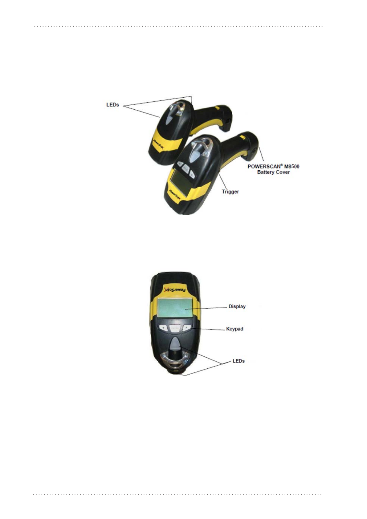
Introduction
General View
Powerscan® M8500 Readers
Figure 2. PowerScan® M8500 Readers
Figure 3. PowerScan® M8500 Reader with Display
16 PowerScan® M8500
Page 19
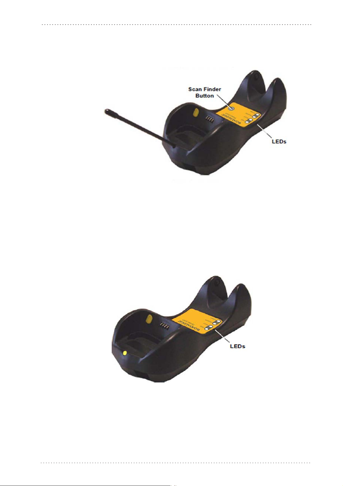
BC-80X0 / C-8000 CRADLES
Figure 4. BC-8000
General View
The label on the cradle contains LED indicators and a scan finder button. When the button
is pressed, the cradle transmits a “broadcast” message. All properly configured scanners
(Radio RX Timeout set to keep the radio “awake”) linked to that base (through a bind or a
join sequence) and w
seconds for 30 seconds. A scanner is considered to be linked when the last transmission ends
properly.
The scan finder works only in stand-alone layout (point to point or multiple
Figure 5. Figure D – C-8000
ithin radio range coverage will emit a beep sequence once every 2
readers).
Product Reference Guide 17
Page 20
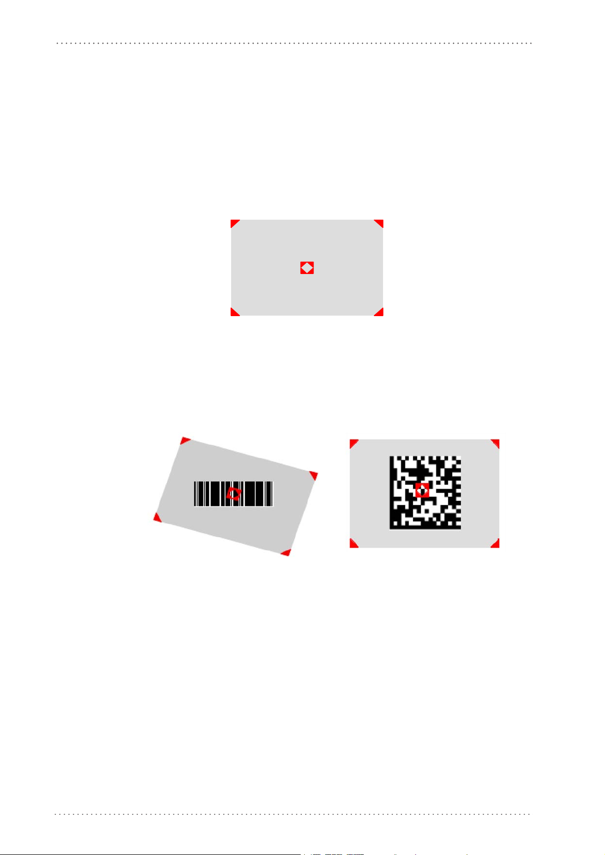
Introduction
Using the Reader
Aiming System
The PowerScan® M8500 reader uses an intelligent aiming system similar to those on
cameras. By partially pulling the trigger, the aiming system indicates a field of view to be
positioned over the code:
Figure 6. Aiming System
When you pull the trigger completely a red beam illuminates the code. If the aiming system
is centered and the entire symbology is within the aiming system, you will get a good read.
The field of view changes size as you move the reader closer or farther away from the code.
Figure 7
The field of view indicated by the aiming system will be smaller when the PowerScan®
PM8500 is closer to the code and larger when it is farther from the code. Symbologies with
smaller bars or elements (mil size) should be read closer to the unit. Symbologies with larger
bars or elements (mil size) should be read farther from the unit. (See "Technical Features"
starting on page 179 for further details).
. Relative Size and Location of Aiming System Pattern
Linear barcode 2D Matrix symbol
18 PowerScan® M8500
Page 21

Normal Operation
PowerScan® M8500 normally functions by capturing and decoding codes.
Point the reader at the target and pull the trigger partially to enable the aiming system.
Then, pull it compl
until the symbol is decoded or timeout is reached. In between the flashes of the reader, the
aiming system keeps on showing the field of view on the target (see Figure 7 on page 18
As you are reading code symbols, adjust the distance at which you are holding the reader.
Configuration Methods
etely to capture and decode the image. The reader will repeatedly flash
).
The PowerScan® M8500 hand-held reader aiming system is designed for
general reading and decoding of 1D and 2D symbols. Some variation in
reading distance will occur due to narrow bar width and other factors.
If reading codes positioned on reflective surfaces, it may be necessary to
tilt the reader with respect to the barcode and/or set the Camera Control
parameters (see
page 102
).
Configuration Methods
Reading Configuration Codes
This manual can be used for complete setup and configuration. If you wish to change the
default settings, you can configure the PowerScan® PM8500 reader by reading the
programming code symbols in this manual. Configuration commands and their relative
arguments are read individually using the symbols in this manual. See "Configuration Using
Code Symbols" starting on page 53.
Using Datalogic Aladdin™
Datalogic Aladdin™ is a multi-platform utility program providing a quick and user-friendly
configuration method via the RS-232/USB-COM interface. Aladdin, available on the CDROM provided, allows you to program the reader by selecting configuration commands
through a user-friendly graphical interface running on a PC. These commands are sent to
the reader over the current communication interface, or they can be printed as barcodes to
be scanned.
It also provides the ability to perform a software upgrade for the connected device (see the
Datalogic Aladdin™ Help On-Line for more details).
Sending Configuration Strings from Host
An alternative configuration method is provided in Appendix B, Host Configuration Strings
using the RS-232 or USB COM interface. This method is
devices need to be configured with the same settings. Batch files containing the desired
parameter settings can be prepared to configure devices quickly and easily.
The PowerScan
connected to a Host by plugging the correct interface cable into the connector and closing the
cable cover.
®
M8500 reader incorporates a multi-standard interface, which can be
particularly useful when many
Product Reference Guide 19
Page 22

Introduction
Autoscanning
Normal Mode
PowerScan® M8500 provides an autoscan command (see page 205), which when enabled,
causes the reader to scan continuously and to monitor the
this way, PowerScan® M8500 is ready to capture any image (containing a potential code)
positioned on a
central zone of its reading area. In
uniform background.
The aiming system can be enabled to indicate the reading area of the potentia
captured. The illumination system can also be enabled when the ambient light conditions
are not sufficient to autodetect the potential code to be captured; furthermore, the
illumination system increases in intensity for an instant when capturing and decoding an
image. A safety time may be defined to prevent PowerScan® M8500 from reading the same
code repeatedly.
If the decoding is completed successfully, the reader starts monitoring the reading area
again. In case
code is present in the central zone of the reading area.
Pattern Mode
The Autoscan pattern mode is particularly advised when reading barcodes positioned on a
non-uniform background. In these cases PowerScan® M8500 may perceive some elements
of the background as barcodes and start the decoding. To avoid this undesired effect, the
Autoscan Pattern Code is placed in the PowerScan® M8500 reading area which prevents
decoding. Using this code as the background, code reading takes place normally by
presenting desired codes to be read over the Pattern Code. Between each code read, the
Pattern Code must be presented to the reader.
The Pattern Code can be printed from this manual (see Autoscan Pattern Code in Appendix F).
In case of low ambient light conditions, PowerScan® M8500 automatically activates the
i
llumination system. If desired, the illuminati
active.
l code to be
of decoding failure, PowerScan® M8500 keeps on decoding until a potential
on system can be enabled so that it is always
Camera Control
Exposure and Calibration
Three automatic control modes are available to optimize the reading performance:
• Automatic based on entire image: ca
whole image. This mode works well in most standard applications. It is the default setting.
• Automatic based on central image: camera co
restricted area positioned in the central zone of the image. This mode is suggested
when reading small codes positioned in a dark and extensive background.
• Automatic for highly reflective surfaces: ca
codes on highly reflective surfaces. This mode is suggested, for example, when reading
codes positioned on plastic or metal surfaces.
Refer to CAMERA CONTROL on page 102 for configuration codes.
20 PowerScan® M8500
mera control mode based on the analysis of the
ntrol mode based on the analysis of a
mera control mode allowing reading of
Page 23

Defining Data Formatting
The string of a decoded code to be sent to the host may be formatted as follows:
• defining simple data formatting (see page 84)
• defining advanced data formatting giving complete flexibility in changing the format
of data (see Adv
anced Data Formatting on page 135).
Defining Data Formatting
When both simple and advanced data formatting are selected the info is pr
following order:
1. the string of the decoded code is processed according to the ad
2. the resulting string is processed according to the selection type rules of the simple data
formatting;
aracter substitution is performed on the resulting string;
3. ch
the r
4. character deletion is performed on
5. code concatenation is performed;
6. code ID is attached to the resulting string;
7. global headers and terminators are attach
The codes to be sent to the host may also be selected or ordered depending on the following
two conditions:
esulting string;
ed to the re
sulting string;
ocessed in the
vanced formatting rules;
One Code Per Scan
• PowerScan® M8500 sends the code being closest to the image center. If the "Central
Code Transmission" command is enabled, only the code containing the image center
will be transmitted (see page 205);
All Codes Per Scan
• The codes to be sent to the host may be ordered either by length or by symbology
starting from the code being closest to the image center (see page 205). When enabling
both these criteria, codes belonging to the same symbology are sent to the host
depending on their length.
Product Reference Guide 21
Page 24

Introduction
Concatenation
It is possible to concatenate up to 4 different codes, set their length and enable the Intercode
Delay between them (the intercode delay is set in the specific interface parameters, see
"Configuration Using Code Symbols" starting on page 53 ). When enabling the delay one or
more global headers and terminators are added to the decoded data. The conc
procedure may occur in different ways depending on the number of codes to be decoded per
image:
One Code Per Scan
• If the code resulting from the single decoding of an image belongs to one of the code
• If the code belongs to the same family of a code previously saved, it overwrites the old
• If the code resulting from the decoding does not
atenation
families to be concatenated, it is saved to the PowerScan® M8500 memory waiting
for other codes to complete the concatenation.
one.
belong to one of the co
be concatenated, it causes the concatenation failure and clears the temporary memory.
If the "Concatenation Failure Transmission" command is set to "Tx codes causing failure" (see page 100), this code will be sent in the output mess
age.
de families to
All Codes Per Scan
• All codes resulting from the decoding of an image and belonging to one of the families
to be concatenated are saved to the PowerScan® M8500 memory waiting for other
codes to complete the concatenation.
• If one or more codes resulting from the decoding belong to the same family of codes
previously save
• When the image contains no code to be concatenated, the concatenation
reader temporar
command is set to "Tx codes causing failure" (see page 100), the codes causing the
concatenation failure will be sent in the output message.
d, they overwrite the old ones.
fails and the
y memory is cleared. If the "Concatenation Failure Transmission"
22 PowerScan® M8500
Page 25
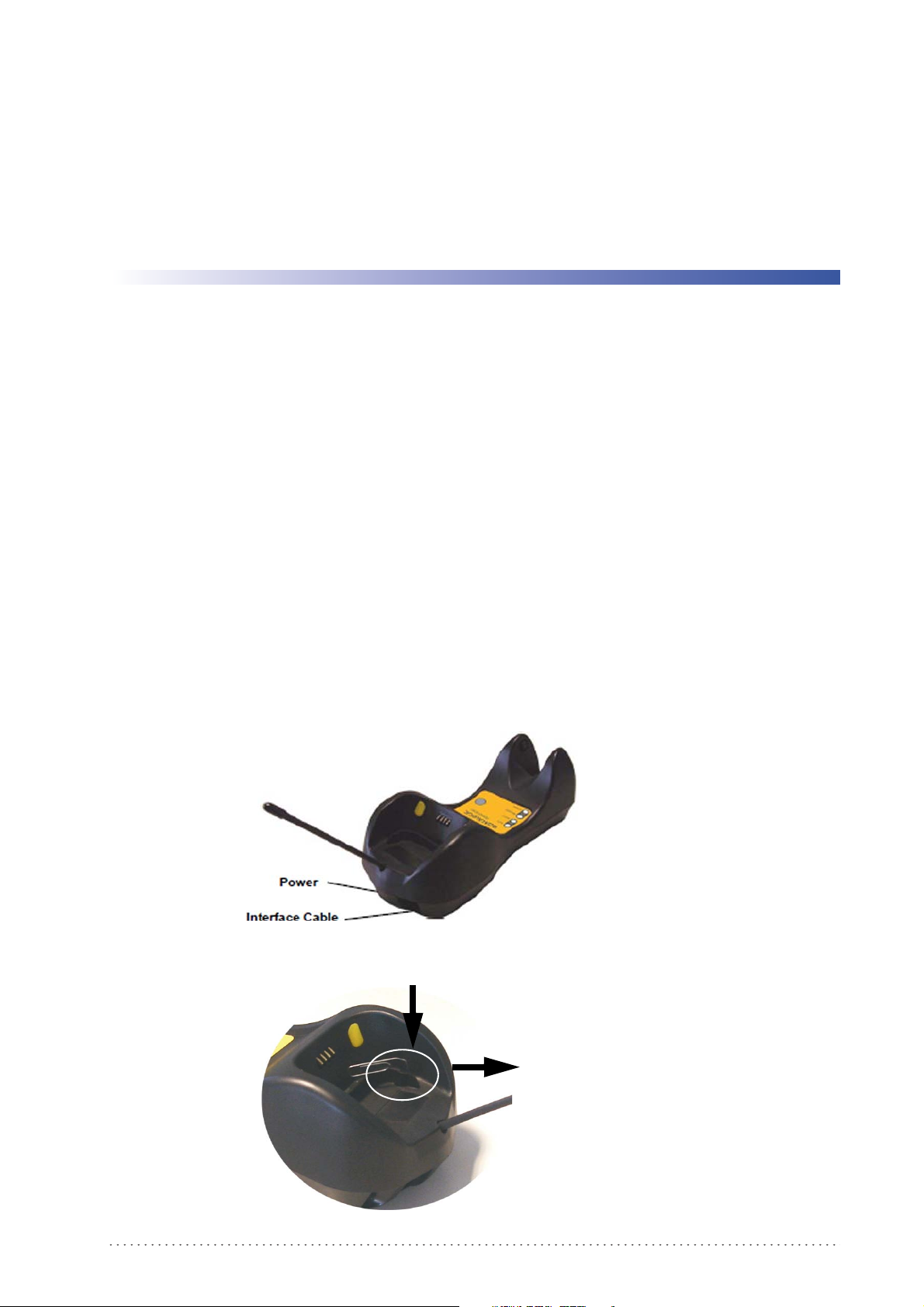
PowerScan M8500 Setup
Package Contents
The following parts are included in the PowerScan® PM8500 package contents:
• PowerScan® PM8500 Hand-Held Reader
• CD-ROM containing the PowerScan® PM8500 Configuration Tools software and
PowerScan® PM8500 Re
• PowerScan® PM8500 Quick Reference Manual
You may want to save your packing material in case you need to ship the reader at some later
time.
Installation
BC-80X0 Interface Cable Connections
The BC-80X0 incorporates a multi-standard interface, which can be connected to a Host by
simply plugging the correct interface cable into the Host connector, placed on the base of
the cradle. In addition the cradle must be connected to an external power supply.
ference Manual
Chapter 2
Figure 8. BC-80X0 Connectors
Figure 9. Disconnecting the BC-80X0 Cable
To disconnect the cable, insert a paper clip or
other similar object into the hole
corresponding to the Host connector on the
body of the cradle.
Push down on the clip while unplugging the
cable.
Product Reference Guide 23
Page 26
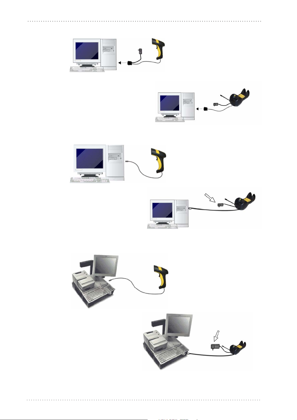
PowerScan M8500 Setup
(If required)
(if
(If required)
RS-232 Connection
USB
IBM USB POS
24 PowerScan® M8500
Page 27
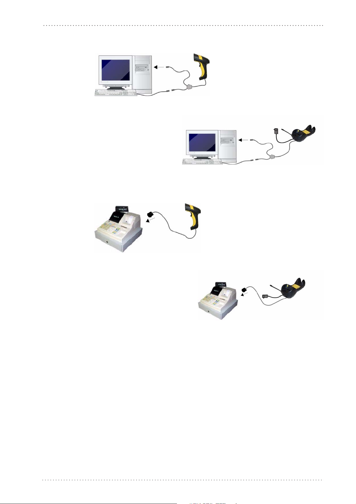
WEDGE Connection
Installation
PEN Emulation Connection
Product Reference Guide 25
Page 28
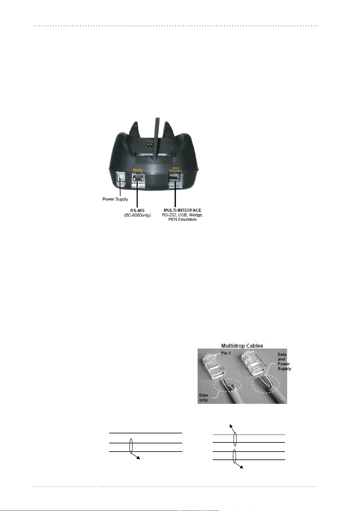
PowerScan M8500 Setup
5
2
RJ45
5
2
RJ45
1 1
VDC-
RS-485-
RS-485+
8
5
2
RJ45
8
5
2
RJ45
1 1
Twisted Pair – RS-485 bus
VDC+
VDC-
RS-485-
RS-485+
Network Connections
BC-8060 Network Connectors
The multidrop network is a bus system which is propagated from one BC-8060 cradle to
another using individual cables. This is possible thanks to the RS-485 connector on the
front panel of the cradle.
Figure 10. Network Connectors
All cradles are connected together within the bus system through the Datalogic RS-485
splitter cable (CAB-428, part number 90A051950), which must be inserted in the RS-485
cradle connector.
Cable length should be kept to a minimum, as with all bus syst
Network Cabling
The Multidrop line is made using RJ45 connectors and a cable having the following
specifications:
• twisted pair AWG 24 wires
• 120 im
• maximum
Pin Function
1 RS-485 +
2 RS-485 3N.C.
4VDC –
5VDC –
6N.C.
7VDC +
8VDC +
ems.
pedance
network cable length 1200 meters
26 PowerScan® M8500
Twisted Pair –RS-485 bus
Twisted Pair - Power supply
Page 29
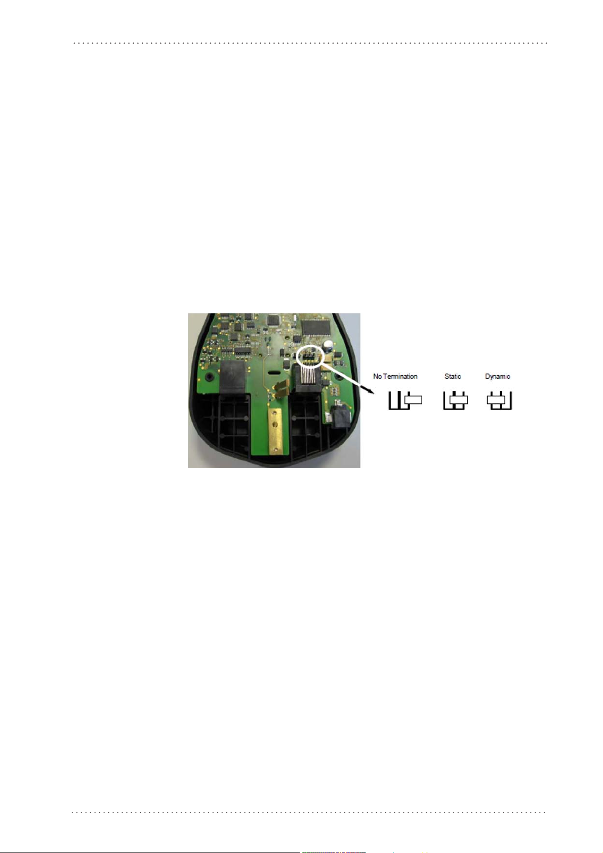
When wiring the multidrop cables, note the following:
• Pin 8 (or 7) can be connected only if the power has to be propagated from a cradle to
ARGATE™ base station or STAR-Box™ converter via the cable.
a ST
• Pins 5 (or 4) should always be connected as refere
• To avoid excessive voltage drop, it is recommended not to propagate power between
BC-8060 cradles when used as battery
The total number of devices, which can be connected to a single power supply,
depends on the power supply voltage, the wire length and resistance and therefore the
voltage drop. Do NOT connect VDC+ between network devices that are individu-
ally powered.
Network Termination
The first and last cradles of the chain (the two ends of the bus) must be properly terminated.
The cradle has an internal terminator that can be selected via jumper. For this selection you
must open the device.
Figure 11. Terminator for Multidrop Network
Network Connections
nce ground.
chargers but to supply each cradle individually.
Static termination works for all network configurations. However, the network is always
under load even when no data transmission takes place.
Dynamic termination can be used for baud rates at or above 38400 and provides less load on
the netw
ork when idle.
Product Reference Guide 27
Page 30
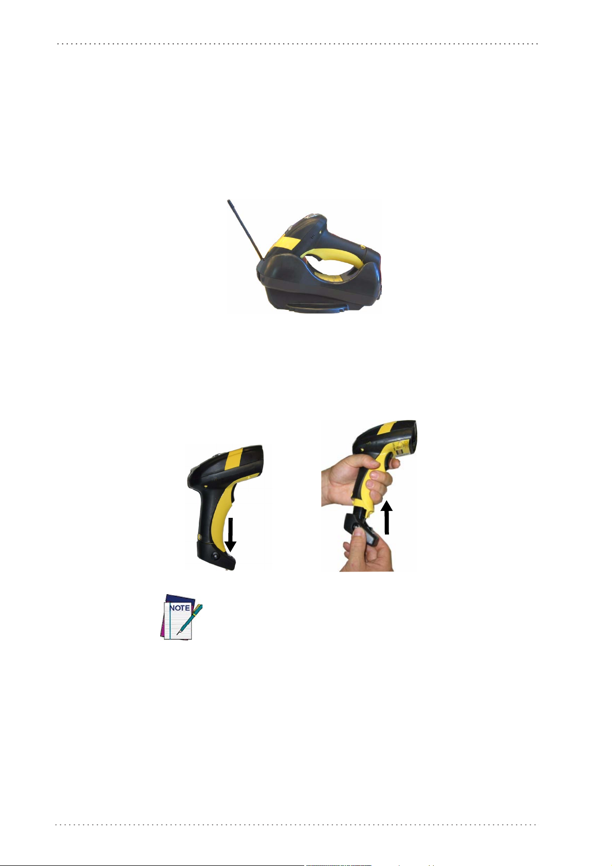
PowerScan M8500 Setup
1
2
PowerScan® M8500 Battery Maintenance
Battery Charging
Once the system is connected and powered, you can place the PowerScan® M8500 into the
cradle to charge the battery.
When the reader is correctly inserted in the cradle, the "Reader" red LED on the cradle goes
on to
indicate that the battery is charging. The "Reader" green LED on the cradle goes on
when the battery is completely charged.
Replacing PowerScan® M8500 Batteries
1. To change the battery pack in your PowerScan® M8500 scanner, push the Release
Button as indicated by Arrow 1 and extract the battery pack from the reader handle.
When the batteries are extracted from the scanner, the timer maintains
the current hour and date for about 1 minute.
2. Then, insert the new battery pack into the reader handle until a ‘click’ is heard and the
Release Button moves back to its neutral position.
28 PowerScan® M8500
Page 31

WARNING
CAUTION
PowerScan® M8500 Battery Maintenance
Do not discharge the battery using any device except for the scanner. When the battery is used
in devices other than the designated product, it may damage the battery or reduce its life
expectancy. If the device causes an abnormal current to flow, it may cause the battery to
become hot, explode or ignite and cause serious injury.
Lithium-ion battery packs may get hot, explode or ignite and cause serious injury if exposed to
abusive conditions. Be sure to follow the safety warnings listed below:
•Do not place the battery pack in fire or heat.
•Do not connect the positive terminal and negative terminal of the battery pack to each other
with any metal object (such as wire).
•Do not carry or store the battery pack together with metal objects.
•Do not pierce the battery pack with nails, strike it with a hammer, step on it or otherwise subject it to strong impacts or shocks.
•Do not solder directly onto the battery pack.
•Do not expose the battery pack to liquids, or allow the battery to get wet.
•Do not apply voltages to the battery pack contacts.
In the event the battery pack leaks and the fluid gets into your eye, do not rub the eye. Rinse
well with water and immediately seek medical care. If left untreated, the battery fluid could
cause damage to the eye.
Always charge the battery at 32° – 104°F (0° - 40°C) temperature range.
Use only the authorized power supplies, battery pack, chargers, and docks supplied by your
Datalogic reseller. The use of any other power supplies can damage the device and void your
warranty.
Do not disassemble or modify the battery. The battery contains safety and protection
devices, which, if damaged, may cause the battery to generate heat, explode or ignite.
Do not place the battery in or near fire, on stoves or other high temperature locations.
Do not place the battery in direct sunlight, or use or store the battery inside cars in hot
weather. Doing so may cause the battery to generate heat, explode or ignite. Using the battery in this manner may also result in a loss of performance and a shortened life expectancy.
Do not place the battery in microwave ovens, high-pressure containers or on induction cookware.
Immediately discontinue use of the battery if, while using, charging or storing the battery,
the battery emits an unusual smell, feels hot, changes color or shape, or appears abnormal
in any other way.
Do not replace the battery pack when the device is turned on.
Do not remove or damage the battery pack’s label.
Do not use the battery pack if it is damaged in any part.
Battery pack usage by children should be supervised.
As with other types of batteries, Lithium-Ion (LI) batteries will lose capacity over time.
Capacity deterioration is noticeable after one year of service whether the battery is in use or
not. It is difficult to precisely predict the finite life of a LI battery, but cell manufacturers
rate them at 500 charge cycles. In other words, the batteries should be expected to take 500
full discharge/charge cycles before needing replacement. This number is higher if partial
discharging / recharging is adhered to rather than full / deep discharging,
The typical manufacturer advertised useful life of LI
batteries is one to three years,
depending on usage and number of charges, etc., after which they should be removed from
service, especially in mission critical applications. Do not continue to use a battery that is
showing excessive loss of capacity, it should be properly recycled / disposed of and replaced.
For most applications, batteries should be replaced after one year of service to maintain
customer satisfaction and minimize safety concerns.
Collect and recycle waste batteries separately from the device in compliance with European
ctive 2006/66/EC, 2002/95/EC, 2002/96/EC and subsequent modifications, US and
Dire
China regulatory and others laws and regulations about the environment.
Product Reference Guide 29
Page 32

PowerScan M8500 Setup
Mounting The BC-80X0 / C-8000 Cradle
The cradle package contains the following items:
• BC-80X0 / C-8000 Cradle
• BC-80X0 Quick Reference / C-8000 Quick Reference
• BC-8000 Antenna • 2 wall-mounting lock hinges
• 2 adhesive strips • 4 rubber feet
•1 horizontal base • 1 inclined base
The cradle (either BC-80X0 or C-8000) can be mounted for portable or fixed desktop
usage, or it can be fixed
usage, while the inclined base provides desktop and wall mounting guaranteeing a
comfortable handling of the PowerScan
Figure 12. BC-80X0/C-8000 Cradle mounted on the Horizontal Base
to a wall. The
horizontal base allows portable and fixed desktop
®
M8500 reader.
Figure 13. BC-80X0/C-8000 Cradle mounted on the Inclined Base
30 PowerScan® M8500
Page 33

Desktop Mounting
1
1
For desktop usage, you can mount the cradle either on the horizontal base, for reduced overall
dimensions, or on the inclined base for a more ergonomic removal and insertion of the reader
onto the cradle.
Figure 14. Horizontal base
Figure 15. Inclined base
PowerScan® M8500 Battery Maintenance
Portable Desktop Use
1. Correctly position the BC-80X0/C-8000 onto the base by sliding it along the mounting tabs until aligned.
2
2. Carefully clean the rubber foot seats of the base to r
reduce adhesion.
3. Remove the protective plastic from the rubber feet and stick them onto the bottom
surface of the base.
4. If mounting th
body of the
Product Reference Guide 31
e BC-80X0 cradle, insert the antenna in the appropriate hole on the
cradle and screw it clockwise until tight.
2
emove any impurities that
could
Page 34

PowerScan M8500 Setup
Horizontal Base
Inclined Base
Fixed Desktop Use
For fixed desktop installation, use the adhesive strips or fixing screws (not provided)
according to your needs.
For mounting with adhesive strips:
1. Position the cradle onto the base by sliding it along the mounting tabs until aligned.
2. Carefully clean the adhesive strip seats of the base to remove any impurities that could
3. Remove the protective plastic from one side of the adhesive strips and stick them onto
4. Position the cables to be connected to the BC-80X0/C-8000 cradle along the dedi-
adhesion.
reduce
the base surf
cated channels, as shown in the figures below:
ace.
5. Remove the plastic from the other side of the strips and affix the base to the table.
6. If mounting the BC-80X0 cradle, insert the antenna in the appropriate
body of the cradle and screw it clockwise until tight.
hole on the
For mounting with screws:
1. Position the cables to be connected to the BC-80X0/C-8000 cradle along the dedicated channels, as shown in the figures below:
2. Position the base on the table and affix it by means of the screws (not provided).
3. Position the cradle on the base by sliding it along the mounting tabs until aligned.
4. If mounting the BC-80X0 cradle, insert the ant
body of the cradle and screw it clockwise until tight.
enna in the appropriate
hole on the
32 PowerScan® M8500
Page 35

PowerScan® M8500 Battery Maintenance
Wall Mounting
1. Remove the yellow caps and insert the two wall mounting lock hinges provided with
your cradle.
2. Position the cables to be connected to the BC-80X0/C-8000 cradle along the dedicated channels (see figures on
3. Complete the procedure using one of the following two methods:
If using the adhesive
• Carefully clean the adhesive strip seats of the base to remove any impurities that
could reduce adhesion.
• Remove the protective plastic from one side of the adhesive strips and stick them
onto the base surface.
•
Remove the plastic from the other side of the strips and affix the base to the wall as
indicated in the figure
If using the mounting screws:
• Using the mounting holes on the base as a pattern, mark the wall where you desire
to mount the BC-8
•
Drill the appropriate size holes and insert the threaded dow
the holes.
strips:
0X0/C-8000.
page 32
below.
.)
els (not provided) into
• Position the base on the wall as indicated in the figure below and affix it by means
of the screws (not provided).
Product Reference Guide 33
Page 36

PowerScan M8500 Setup
Figure 16. Inclined Base Wall-Mounting
4. Attach the cradle on the base by sliding it along the mounting tabs until aligned.
5. If mounting the BC-80X0 cradle, insert the antenna in the appropriate
body of the cradle and screw it clockwise until tight.
There are two basic system layouts that can be employed: Stand-alone systems (including
Point-to-Point layouts) and
Multidrop STAR-System™ Networks.
hole on the
34 PowerScan® M8500
Page 37

System and Network Layouts
®
M8500
Stand-Alone Layouts
Figure 17. Point-to-Point Reader Layout
System and Network Layouts
Figure 18. Stand-Alone Layout with Multiple Readers
PowerScan
Host
BC-80X0
In stand-alone systems, each cradle is connected to a single Host.
M8300
JOIN
BIND
Product Reference Guide 35
Page 38

PowerScan M8500 Setup
Multiple Stand-Alone Layouts
Many stand-alone connections can operate in the same physical area without interference,
provided all readers and cradles in the system have different addresses.
Figure 19. Multiple Stand-alone Systems in the Same Area
Since the cradles can communicate to multiple PowerScan® M8500 readers, you might find
it useful to employ one or more C-8000 battery chargers in addition to the BC-80X0 cradle,
so that the battery re-charging operation can be performed for several scanners at the same
time.
Figure 20. C-BOX Layout
In this layout the BC-80X0 cradle is connected by a dedicated cable using the RS-232
interface to a C-BOX connection box as part of a fixed scanner network. This allows the
flexibility of a hand-held reading station integrated into a variety of fixed scanning
applications so that all readers (both fixed and hand-held), in the system provide
communications to the Host.
The various C-BOX models provide many interface types for the Host system such as RS-232,
RS-485, and Profibus.
36 PowerScan® M8500
Page 39

Multidrop STAR-System™ Network Layouts
Even though many stand-alone systems can operate in the same physical area without
interfering with each other, it may be desirable to bridge data from multiple base stations in a
network to a
networks. These networks provide seamless active roaming for any RF reading device in the
system.
Host Master Layout
Figure 21. Example of Multidrop STAR-System™ Network with Host as Master
single Host. PowerScan® M8500 readers are compatible with STAR-System™
System and Network Layouts
A. Host Master with STAR-Link™
B. STAR-Box™ converter
C. BC-8060 slave cradles
D. STARGATE™ base stations
In this layout the Host acts as the Master using STAR-Link™ software. The Host is
connected in RS-232 to a STAR-Box™ converter, which is connected to the first slave in
the RS-485 network. In this way the base stations provide communications between a
Host and all readers in the system. STARGATE™ base stations are used as slaves in this
network. The Slaves at the ends of the network must be terminated (reference the
STARGATE™ and STAR-Box™ Installation Manuals and
27).
See
"PowerScan® M8500/STAR-System™ Setup"
Network Setup"
configuration specifications.
on page 45, or the Datalogic Aladdin™ Help On-Line, for system
on page 43 and
"Network Termination"
"BC-8060 STAR-System™
single
on page
Product Reference Guide 37
Page 40

PowerScan M8500 Setup
BC-8060 Master Layout
Figure 22
A. Host
B. BC-8060 Master cradle
C. BC-8060 Slave cradles
D. STARGATE™ base station
. Example of Multidrop STAR-System™ Network with BC-8060 as Master
In this layout a BC-8060 cradle acts as the Master. The Host is connected to the
BC-8060 Master using any one of the multi-standard interfaces (RS-23
PEN Emulation). The Master is then connected to the slaves in the RS-485 network. In this
way the slave cradles provide communications between a
system. STARGATE™ base stations can also be used as slaves in this network. The devices at
the ends of the network must be terminated (see
See "PowerScan® M8500/STAR-System™ Setup" on page
45
System™ Network Setup" on page
system configuration specifications.
, or the Datalogic Aladdin™ Help On-Line, for
"Network Termination"
single Host and all readers in the
43
2, USB, WEDGE, or
on page 27).
and "BC-8060 STAR-
Master BC-8060 Network Troubleshooting
Two diagnostic strings can be sent via RS-232 from the Host to the Master cradle in order
to have feedback about the network itself.
#+LSlave
Returns a list of all the Slaves recognized at boot up.
Example: In a network where the
address 0001, the response is:
188
1
#+Alive<xxxx>
Executes a continuous Alive request to the slave xxxx in order to monitor the performance of
the connection. A diagnost
Master cradle has address 0188 and one Slave cradle with
ic message is displayed on the Host.
Example: If this command is sent for s
/*32: BC-80X0 SOFTWARE RELEASE 1.00 20/10/2006*/
if there are no communication errors
/*32: FAIL*/
if there are communication errors.
To exit from this command, reset the system by cycling power to the Master c
lave cradle with address 0032, the response is:
radle.
38 PowerScan® M8500
Page 41

Setup Procedures
Begin Setup
by choosing the setup
procedure for your PowerScan
®
reader as indicated below.
End of Setup
Your reader is now ready to read barcodes
using the default settings.
Stand Alone Applications
PowerScan
®
M8500/BC-80X0
page 39
page 45
Optional
page 45
Step 1
multiple readers per BC-8000
PowerSc an
®
M8500/STAR-Modem™
in Stand Alone Mode
STAR-System™ Network Applications
BC-8000
page 43
STAR-System™ Applications
PowerSc an® M8500/STAR-System™
page 40
•STARGATE™
• BC-8000 Network
• STAR-Modem™ in STAR-System™ Mode
For PowerScan® M8500 Series readers, the setup procedures depend on two basic
applications, Stand-alone or STAR-System™.
Setup Procedures
Stand-alone applications allow communication with th
page 40
(
), or by the STAR-Modem™ radio modem (
STAR-System™ applications allow communication with the
e Host by either the BC-80X0 cradle
page 42
).
Host through an RS-485
network by the STARGATE™ RF base station or by the BC-8000 cradle (
Proceed as shown in the following diagram:
page 43
and 45).
PowerScan® M8500/BC-80X0 Point-to-Point Setup
Product Reference Guide 39
A rapid configuration procedure has been devised for point-to-point applications where a
single reader is associated exclusively with its own BC-80x0 base station and where it is not
necessary to set the Date and Time parameters.
A special pre-printed bind-address label provided in the BC-80x0 base station package
be used to bind the PowerScan
on the label. The address is also written numerically on the label to be easily recognized.
®
M8500 reader to the base station with the address coded
can
Valid addresses are in the range from 0000 to 1999. Make sure that all cradles used in the
same area have different addresses.
To rapidly configure your point-to-point application:
Apply the bind-address label onto the BC-80x0 base station as indicated in the BC-80x0 Quick
1.
Reference Guide.
When the BC-80X0 cradle is connected and powered, read the
2.
PowerScan
The green LED on the PowerScan® M8500 will blink: the reader is ready to be positioned onto the
cradle.
®
M8500 to the BC-80X0 cradle.
Bind-Address
label to pair the
Page 42

PowerScan M8500 Setup
Firmly position the reader onto the cradle within 10 seconds, a beep will be emitted, signaling
3.
that the BC-80X0 cradle has been paired to the PowerScan
reader will go off.
If it ever becomes necessary to change the reader, just read the bindaddress label applied to the cradle and position the new reader onto the
cradle.
Do not use multiple readers with this configuration method.
Configure the BC-80X0 cradle; refer to the “BC-80X0 Quick Reference Guide”.
4.
®
M8500, and the green LED on the
END of procedure. YOUR READER IS NOW READY TO READ CODES.
PowerScan® M8500/BC-80X0 Stand-Alone Setup
Read the restore default parameters code below.
1.
Restore PowerScan® M8500 Default
Follow the procedure below to set the radio address and bind PowerScan® M8500 to the
BC-80X0 cradle.
2.
3.
Enter Configuration
Set Date
+
six digits for Day, Month and Year (DDMMYY)
4.
Set Time
+
four digits for Hour and Minutes (HHMM)
40 PowerScan® M8500
Page 43

Setup Procedures
5.
four digits for the PowerScan® M8500 Address (from
All readers used in the same area must have different addresses.
6.
Read the
7.
cated to the cradle. Any previously
Bind
code to pair the PowerScan® M8500 to the BC-80X0 cradle. The reader is dedi-
"Using Multiple M-Series Readers with Same Cradle"
Set Radio Address
+
0000
Exit and Save Configuration
bound
reader will be excluded.
To connect several readers to the same cradle see
on page 42
Bind
to
1999
).
The green LED on the PowerScan® M8500 will blink; the reader is ready to be inserted into the
cradle.
Firmly insert the reader into the BC-80X0 cradle within 10 seconds, a beep will be emitted, sig-
8.
naling that the BC-80X0 cradle has been paired to the PowerScan
the reader will go off.
Read the BC-80X0 restore default code:
9.
Restore BC-80X0 Default
®
M8500, and the green LED on
Go to
"Interface Selection"
on page 47.
Product Reference Guide 41
Page 44

PowerScan M8500 Setup
Using Multiple M-Series Readers with Same Cradle
If you want to use several M-Series readers with the same BC-80X0 cradle, you must first
Bind the cradle with one of the readers (see previously described configuration procedure).
Successive readers can be associated with the same crad
procedure substituting the Bind command with Join (see
7.
The green LED on the PowerScan® M8500 will blink: the reader is ready to be positioned onto
the cradle.
Complete
step 8. on page 41
Join
.
le by following the configuration
step 7. on page 41
END of procedure.
All readers associated with the same cradle must have different
addresses.
CAUTION
YOUR READER IS NOW READY TO READ BARCODES.
To change the defaults see "
Configuration Parameters"
on page 53.
).
PowerScan® M8500/STAR-Modem™ in Stand-Alone Mode
To configure a PowerScan® M8500 reader to communicate with STAR-Modem™ in
Stand-alone Mode, follow the procedure in "
on page 40, substituting steps 6 and 7 with those below:
Setup"
6.
Read the code above and the four-digit address of the STAR-Modem™.
7.
STAR-Modem™ Address
Exit and Save configuration
END of procedure.
PowerScan® M8500/BC-80X0 Stand-Alone
YOUR READER IS NOW READY TO READ BARCODES.
To change the defaults see"
Configuration Parameters"
on page 53.
42 PowerScan® M8500
Page 45

PowerScan® M8500/STAR-System™ Setup
The following procedure allows configuring a PowerScan® M8500 reader to communicate
with various STAR-System™ devices such as STARGATE™ RF base stations.
Setup Procedures
1.
2.
3.
4.
Restore PowerScan® M8500 Default
Enter Configuration
Set Date
+
six digits for Day, Month and Year (DDMMYY)
Set Time
+
four digits for Hour and Minutes (HHMM)
Set the connection according to the length of the codes to be read:
5.
Code Length 240 Characters
Code Length >240 Characters
(not for systems with BC-8000 as Master)
Product Reference Guide 43
Page 46

PowerScan M8500 Setup
6.
four digits from the Numeric Table in the range 0000-1999.
All readers must have different addresses.
7.
Read the code above and the four-digit address of the First STAR-System™ device in
8.
Set Radio Address
+
First STAR-System™ Address
the system.
Set Last STAR-System™ Address
Read the code above and the four-digit address of the Last STAR-System™ device in
the system.
Whenever the system is composed of a single base station, the first and
last base station addresses (steps 7 and 8) must have the same value.
9.
Exit and Save Configuration
END of procedure.
YOUR READER IS NOW READY TO READ BARCODES.
To change the defaults see "
Configuration Parameters"
on page 53.
44 PowerScan® M8500
Page 47

BC-8060 STAR-System™ Network Setup
When the BC-8060 cradle model is used in an RS-485 network, it must be initially
configured. To do this using configuration barcodes, follow the procedure below using any
PowerScan
®
M8500 reader.
Setup Procedures
1.
2.
3.
Read the
ration.
Set BC-8060 Address
+
four digits for the BC-8060 Address (from
All cradles used in the network must have different addresses.
Exit and Save configuration
Bind
code to pair the PowerScan® M8500 to the BC-8060 cradle for configu-
Bind
0000
to
1999
).
The green LED on the PowerScan® M8500 will blink; the reader is ready to be inserted
into the cradle.
Firmly insert the reader into the BC-8060 cradle within 10 seconds, a beep will be
4.
emitted, signaling that the BC-8060 cradle has been paired to the PowerScan
and the green LED on the reader will go off.
Read the BC-8060 restore default code:
5.
Restore BC-8060 Default
®
M8500,
Product Reference Guide 45
Page 48

PowerScan M8500 Setup
6.
END of procedure.
For Host Master Network Layouts (see page 37), the network configuration parameters can
be changed through STAR-Link™ software running on the PC. Star-Link™ software can
be downloaded free from the web site: www.scanning.datalogic.com.
Read the desired Enable Network code.
Enable RS-485 Master
Enable RS-485 Slave
For BC-8060 Master Network Layouts (see page 38), the network configuration parameters
can be changed either through the Datalogic Aladdin™ configuration software running on
the PC or by reading the barcode selections in the Network section of this manual starting
on page 79. If using configuration barcodes, it is advised to completely configure the cradles
before reconfiguring the PowerScan
After completing the BC-8060 cradle configuration and connections in
the network, you must reconfigure the PowerScan
the STAR-System™ procedure on page 43.
®
M8500 reader (see below).
®
M8500 reader using
46 PowerScan® M8500
Page 49

Interface Selection
Read the interface selection code for your application.
Interface Selection
RS-232
Standard
POS TERMINALS
Nixdorf Mode A
ICL Mode
For POS terminal default settings refer to
page 174
PEN
Fujitsu
.
Product Reference Guide 47
Page 50

PowerScan M8500 Setup
WEDGE
IBM AT or PS/2 PCs
IBM XT
PC Notebook
IBM SURE1
IBM Terminal 3153
IBM TERMINALS 31XX, 32XX, 34XX, 37XX:
To select the interface for these IBM Terminals, read the correct KEY TRANSMISSION
code. Select the
KEYBOARD TYPE if necessary (default = advanced keyboard).
KEY TRANSMISSION MODE
make-only keyboard
make-break keyboard
48 PowerScan® M8500
Page 51

Interface Selection
WEDGE (continued)
KEYBOARD TYPE
advanced keyboard
typewriter keyboard
ALT MODE
The ALT-mode selection allows barcodes sent to the PC to be interpreted correctly
independently from the Keyboard Nationality used. You do not need to make a Keyboard
Nationality selection. (Default=NumLock Unchanged).
Make sure the NumLock key on your keyboard is ON.
IBM AT - ALT mode
ANSI Keyboard
PC Notebook - ALT mode
WYSE TERMINALS
PC Keyboard
ASCII Keyboard
VT220 style Keyboard
Product Reference Guide 49
Page 52

PowerScan M8500 Setup
Conne ct device to
Host
Select desired USB
interface code
(USB-KBD is default)
Read test codes.
Device is REA DY
Load drivers
(if requeste d)
Load drivers
(
)
reader LED blinks
reader LED off - BEEP OK
First Start
-Up
1
2
USB Configuration
The USB interface is available for BC-80x0 and C-8000 devices and is compatible with the
following Operating Systems:
USB Start-up
As with all USB devices, upon connection, the Host performs several checks by
communicating with the device. During this phase normal operations are suspended. Two
basic conditions must be met before the device is ready, the correct USB driver must be
loaded and sufficient power must be supplied to the reader.
DIGITAL TERMINALS
VT2xx/VT3xx/VT4xx
Windows 98 (and later) IBM POS for Windows
Mac OS 8.0 (and later) 4690 Operating System
1. For all systems, the correct USB driver for the default
USB-KBD interface is included in the Host Operating
System and will either be
loaded automatically or will be
suggested by the O.S. and should therefore be selected
from the dialog box (the first time only).
Normally the Host supplies sufficient power to the
if requested
device and the start-up phase ends correctly. (The
reader's LED stops blinking and the reader emits the
beep OK signal).
In rare cases, if the Host does not supply sufficient
power to the device, a dialog box will appear on the
and the device will be blocked (the reader's LED
continues blinking). In this case, disconnect the USB
device cable
at the Host (the reader's LED stops
Host
blinking), and then try a different USB port as indicated
by the Operating System message. (The device emits the
beep OK signal. You can now read codes).
2. At this point you can read the USB interface configuration code according to your
application. Load drivers from th
e O.S. (if requested). When configuring the USB-COM
interface, the relevant files and drivers must be installed from the USB Device Installation
software, which can be downloaded from the web page
http://www.scanning.datalogic.com
The device is ready. Successive start-ups will automatically recognize the previously loaded
drive
rs.
.
50 PowerScan® M8500
Page 53

USB Parameters
USB-KBD
USB-KBD-ALT-MODE
USB-KBD-APPLE
Interface Selection
USB-COM*
USB-IBM-Table Top
USB-IBM-Hand Held
* When configuring USB-COM, the relevant files and drivers must be installed from
the USB Device Installation software, which can be downloaded from the web site
http://www.scanning.datalogic.com.
Product Reference Guide 51
Page 54

PowerScan M8500 Setup
NOTES
52 PowerScan® M8500
Page 55

Configuration Using Code Symbols
This section provides programming barcodes to configure your reader by changing the
default settings. For details about additional methods of programming, see "Configuration
Methods" on page 19.
You must first enable your reader to read barcodes in order to use this
section. If you have not done this, go to
page 39
Configuration Parameters
Once the reader is set up, you can change the default parameters to meet your application
needs. Refer to "Default Settings" on page 189 for initial configuration in order to set the
default values and select the interface for your application.
Chapter 3
Setup Procedures, starting on
and complete the appropriate procedure.
The configuration
desired function based on its reference group.
The first four groups are for Standard Interface parameter conf
M8500/BC-
parameters are divided into logical groups, making it easy to find the
iguration for all PowerScan
80X0 Stand-alone configurations only.
• "RS-232 PARAMETERS" on page 55
• "USB PARAMETERS" on page 60
• "WEDGE PARAMETERS" on page 67
• "PEN EMULATION" on page 74
This group of parameters is applicable only to BC-8060 Network configurations:
• "NET
The following parameter groups are common to all interface applications:
• "D
• "CAMERA CONTROL" on page 102 covers the control mode managing the camera.
• "AIMING SYSTEM" on page 103
• "CODE SELECTION" on page 104 parameters allow configuration of a personalized mix of
• "READING PARAMETERS" on page 117 control various operating modes and indicators
WORK PARAMETERS" on page 79
ATA FORMAT" on pa g e 84 parameters control the messages sent to the Host system.
allows you to enable or disable the Aiming System.
codes, code families and their options.
status functioning.
• "RADIO PARAMETERS" on page 124 allow configuration of radio control parameters.
• "DISPLAY and KEYPAD PARAMETERS" on page 130 (some M8500 series models only)
allow configuration of reader display parameters.
Product Reference Guide 53
Page 56

Configuration Using Code Symbols
Reading Configuration Barcodes
You must first enable your reader to read barcodes in order to use this
section. If you have not done this, go to
page 39
To configure your reader:
1. Read the instructions for the setting that you want to configure.
1. If needed, go to Appendix F with the hex-numeric table and bookmark it or print it so
you can use it during the device configuration.
2. Read the En
figuration.
ter C
and complete the appropriate procedure.
onfiguration code ONCE, available at the top of each page of con-
Setup Procedures, starting on
3. Modify the desired parameters in one or mor
for each group.
4. Read the Exit and Sav
page of configuration.
Reference notes providing detailed information for the more complex parameters
in "References" beginning on page 155.
e Configuration code ONCE, available at the top of each
e sections, follow
ing the procedures given
are given
54 PowerScan® M8500
Page 57

RS-232 PARAMETERS
PowerScan® M8500/BC-80X0 configurations only
Baud Rate
Parity
Data Bits
Stop Bits
Handshaking
ACK/NACK Protocol
FIFO
Inter-character Delay
1. Read the Enter Configuration code ONCE, available at the top of each page.
on page 56
on page 56
on page 57
on page 57
on page 57
on page 58
on page 58
on page 58
2. Read configuration codes from the desired groups.
3. Read the Exit and Save Configuration code ONCE, available at the top of each
programming page.
Product Reference Guide 55
= Read the code and follow the procedure given
= Default value
Page 58

Enter Reader Configuration
300 baud
1200 baud
4800 baud
Exit and Save Reader Configuration
RS-232 PARAMETERS
Baud Rate
600 baud
2400 baud
19200 baud
none
9600 baud
38400 baud
Parity
even parity
odd parity
56 PowerScan® M8500
Page 59

\
Enter Reader Configuration
Exit and Save Reader Configuration
RS-232 PARAMETERS
Data Bits
7 bits
8 bits
9 bits
1 stop bit
disable
Stop Bits
2 stop bits
Handshaking
hardware (RTS/CTS)
software (XON/XOFF)
RTS always ON
See "Handshaking" on page 155 for details.
Product Reference Guide 57
Page 60

Enter Reader Configuration
Exit and Save Reader Configuration
RS-232 PARAMETERS
ACK/NACK Protocol
disable
enable
See "ACK/NACK Protocol" on page 156 for details on implementing this parameter with
PowerScan® M8500.
FIFO
disable
See "FIFO" on page 156 for more information.
Inter-character Delay
delay between characters transmitted to Host
Read 2 numbers from the Hex & Numeric Table where:
00 = DELAY disabled
01-99 = DELAY from 1 to 99 milliseconds
delay disabled
enable
58 PowerScan® M8500
Page 61

\
Enter Reader Configuration
Exit and Save Reader Configuration
RS-232 PARAMETERS
RX Timeout
timeout control in reception from Host
Read 2 numbers from the Hex & Numeric Table where:
00 = TIMEOUT disabled
.1
to
9.9
01-99 = TIMEOUT from
rx timeout 5 seconds
seconds
See "RX Timeout" on page 157 for details.
Serial Trigger Lock
enable and select characters
disabled
Read 2 characters from the Hex & Numeric Table in the range 00-FE where:
• First Character enables device trigger
• Second Character inhibits device trigger until the first character is received
again.
Product Reference Guide 59
Page 62

USB PARAMETERS
USB-COM
Handshaking
ACK/NACK Protocol
FIFO
on page 61
on page 61
on page 61
Inter-character Delay
RX Timeout
Serial Trigger Lock
on page 62
on page 63
USB-KBD
Keyboard Nationality
FIFO
on page 65
Inter-character Delay
Inter-code Delay
on page 66
USB Keyboard Speed
on page 62
on page 64
on page 66
on page 66
USB-IBM
o parameter selection required.
N
1. Read the Enter Configuration code ONCE, available at the top of each page.
2. Read configuration codes from the desired groups.
= Read the code and follow the procedure given
= Default value
3. Read the Exit and Save Configuration code ONCE, available at the top of each
programming page.
60 PowerScan® M8500
Page 63

\
Enter Reader Configuration
Exit and Save Reader Configuration
USB PARAMETERS
USB-COM
Handshaking
disable
hardware (RTS/CTS)
software (XON/XOFF)
RTS always ON
See "Handshaking" on page 155 for details.
ACK/NACK Protocol
disable
enable
See "ACK/NACK Protocol" on page 156 for details on implementing this parameter with
PowerScan® M8500.
FIFO
disable
enable
See "FIFO" on page 156 for more information.
Product Reference Guide 61
Page 64

Enter Reader Configuration
Read 2 numbers from the Hex & Numeric Table where:
00 = DELAY disabled
01-99 = DELAY from 1 to 99 milliseconds
delay disabled
Exit and Save Reader Configuration
USB PARAMETERS
USB-COM (cont)
Inter-character Delay
delay between characters transmitted to Host
RX Timeout
timeout control in reception from Host
Read 2 numbers from the Hex & Numeric Table where:
00 = TIMEOUT disabled
.1
01-99 = TIMEOUT from
rx timeout 5 seconds
See "RX Timeout" on page 157 for details.
to
9.9
seconds
62 PowerScan® M8500
Page 65

\
Enter Reader Configuration
Exit and Save Reader Configuration
USB PARAMETERS
USB-COM (cont)
Serial Trigger Lock
disabled
enable and select characters
Read 2 characters from the Hex & Numeric Table in the range 00-FE where:
• First Character enables device trigger
• Second Character inhibits device trigger until the first character is received
again.
Product Reference Guide 63
Page 66

Enter Reader Configuration
Exit and Save Reader Configuration
USB PARAMETERS
USB-KBD
Keyboard Nationality
Not Available for USB-KBD-ALT-MODE Interface.
This parameter default value is restored through the Interface Selection code and not
Restore Default.
Belgian
English (UK)
French
Italian
Swedish
German
Spanish
USA
64 PowerScan® M8500
Page 67

\
Enter Reader Configuration
Exit and Save Reader Configuration
USB PARAMETERS
USB-KBD (cont)
The Japanese and Eastern Block Keyboard Nationality selections are valid only for IBM AT
compatible PCs.
Japanese
Russian (Latin)
Russian (Cyrillic)
Slovenian, Croatian, Serbian
(Latin)
Czech Republic
disable
Hungarian
Romanian
FIFO
enable
See "FIFO" on page 156 for details.
Product Reference Guide 65
Page 68

Enter Reader Configuration
Read 2 numbers from the Hex & Numeric Table where:
00 = DELAY disabled
01-99 = DELAY from 1 to 99 milliseconds
delay disabled
Exit and Save Reader Configuration
USB PARAMETERS
USB-KBD (cont)
Inter-character Delay
delay between characters transmitted to Host
Inter-code Delay
delay between codes transmitted to Host
Read 2 numbers from the Hex & Numeric Table where:
00 = DELAY disabled
01-99 = DELAY from 1 to 99 milliseconds
delay disabled
USB Keyboard Speed
Normal
Fast
66 PowerScan® M8500
Page 69

WEDGE PARAMETERS
PowerScan® M8500/BC-80X0 configurations only
Keyboard Nationality
Caps Lock
on page 68
on page 69
Caps Lock Auto-Recognition (IBM AT
compatible only)
Num Lock
Inter-character Delay
Inter-code Delay
Keyboard Setting
Control Character Emulation
on page 70
on page 70
on page 70
on page 71
on page 71
on page
73
1. Read the Enter Configuration code ONCE, available at the top of each page.
2. Read configuration codes from the desired groups.
= Read the code and follow the procedure given
= Default value
3. Read the Exit and Save Configuration code ONCE, available at the top of each
programming page.
Product Reference Guide 67
Page 70

Enter Reader Configuration
Belgian
French
Exit and Save Reader Configuration
WEDGE PARAMETERS
Keyboard Nationality
English (UK)
German
Italian
Swedish
Spanish
USA
68 PowerScan® M8500
Page 71

\
Enter Reader Configuration
Exit and Save Reader Configuration
WEDGE PARAMETERS
The Japanese and Eastern Block Keyboard Nationality selections are valid only for IBM AT
compatible PCs.
Japanese
Russian (Latin)
Russian (Cyrillic)
Hungarian
Slovenian, Croatian, Serbian
(Latin)
Czech Republic
caps lock OFF
Romanian
Caps Lock
caps lock ON
Select the appropriate code to match your keyboard caps lock status.
Caps lock manual configuration is ignored when Caps Lock
Auto-Recognition is enabled.
For PC Notebook interface selections, the caps lock status is automatically recognized; therefore this command is not necessary.
Product Reference Guide 69
Page 72

Enter Reader Configuration
Exit and Save Reader Configuration
WEDGE PARAMETERS
Caps Lock Auto-Recognition (IBM AT compatible only)
disable
enable
Num Lock
toggle num lock
num lock unchanged
This selection is used together with the Alt Mode interface selection for AT or Notebook
PCs.
It changes the way the Alt Mode procedure is executed; therefore
• if your keyboard Num Lock is norma
• if your keyboard Num Lock is normally off use toggle num lock
In
this way the device will execute the Alt Mode procedure correctly for
lly on use num lock unchanged
it should be set as follows:
your application.
Inter-character Delay
delay between characters transmitted to Host
Read 2 numbers from the Hex & Numeric Table where:
00 = DELAY disabled
01-99 = DELAY from 1 to 99 milliseconds
delay disabled
70 PowerScan® M8500
Page 73

\
Enter Reader Configuration
Exit and Save Reader Configuration
WEDGE PARAMETERS
Inter-code Delay
delay between codes transmitted to Host
Read 2 numbers from the Hex & Numeric Table where:
00 = DELAY disabled
01-99 = DELAY from 1 to 99 milliseconds
delay disabled
Keyboard Setting
Alphanumeric Keyboard Setting
The device (reader or cradle) can be used with terminals or PCs with various keyboard types
and nationalities through a simple keyboard setting procedure.
The type of computer or terminal must be selected before activating th
command.
Keyboard setting consists of communicating to the
to the keyboard used in the application. The keys must be set in a specific order.
Press and release a key to set it.
Some characters may require more than one key pressed simultaneously during norm
(refer to the manual of your PC or terminal for keyboard use). The exact sequence must be
indicated to the reader in this case pressing and releasing the different keys.
Example:
If one has to press the "Shift" and "4" keys simultaneous
character "$" to the video, to set the "$", press and release "Shift" then press and release "4".
Each pressed and released key must generate an acoustic signal on the device; other
repress the key. Never press more than one key at the same time, even if this
corresponds to the normal use of your keyboard.
Press "Backspace" to correct a wrong key entry. In
device how to send
ly on the keyboard to transmit th
this case the device emits 2 beeps.
e keyboard setting
data corresponding
al use
e
wise
"CAPS LOCK" and "NUM LOCK" must be off before starting the keyboard
setting procedure. "SHIFT" must be pressed for each character and cannot be substituted by "CAPS LOCK".
setting the alphanumeric keyboard
Read the code above.
Press the keys shown in the following table according to their numerical order.
Product Reference Guide 71
Page 74

Enter Reader Configuration
Exit and Save Reader Configuration
WEDGE PARAMETERS
Some ASCII characters may be missing as this depends on the type of keyboard: these are
generally particular characters relative to the various national symbologies. In this case:
• The first 4 characters (Shift, Alt, Ctrl, and Backspace) can only be substituted
with keys not used, or substituted with each other.
• Characters can be substituted with other single symbols (e.g. "SPACE") even if not
cluded in the barcode set used.
in
• Characters can be substituted with others corresponding to your keyboard.
The device signals the end of the procedure with 2 beeps
indicating the keys
registered.
01 : Shift
02 : Alt
03 : Ctrl
04 : Backspace
05 : SPACE 28 : 7 51 : N
06 : ! 29 : 8 52 : O
07 : " 30 : 9 53 : P
08 : # 31 : : 54 : Q
09 : $ 32 : ; 55 : R
10 : % 33 : < 56 : S
11 : & 34 : = 57 : T
12 : ' 35 : > 58 : U
13 : ( 36 : ? 59 : V
14 : ) 37 : @ 60 : W
15 : * 38 : A 61 : X
16 : + 39 : B 62 : Y
17 : , 40 : C 63 : Z
18 : - 41 : D 64 : [
19 : . 42 : E 65 : \
20 : / 43 : F 66 : ]
21 : 0 44 : G 67 : ^
22 : 1 45 : H 68 : _ (underscore)
23 : 2 46 : I 69 : `
24 : 3 47 : J 70 : {
25 : 4 48 : K 71 : |
26 : 5 49 : L 72 : }
27 : 6 50 : M 73 : ~
74 : DEL
have been
Do not place the reader onto the BC-80X0 cradle during this procedure.
Otherwise, the battery charging will occur, modifying the LED’s functioning.
CAUTION
72 PowerScan® M8500
Page 75

\
Enter Reader Configuration
Exit and Save Reader Configuration
WEDGE PARAMETERS
Control Character Emulation
Ctrl + Shift + Key
Ctrl + Key
Product Reference Guide 73
Page 76

PEN EMULATION
PowerScan® M8500/BC-80X0 configurations only
Operating Mode
Minimum Output Pulse
Conversion to Code 39
Overflow
Output Level
Idle Level
Inter-Block Delay
1. Read the Enter Configuration code ONCE, available at the top of each page.
2. Read configuration codes from the desired groups.
= Read the code and follow the procedure given
on page 75
on page 76
on page 76
on page 77
on page 77
on page 78
on page 78
= Default value
3. Read the Exit and Save Configuration code ONCE, available at the top of each
programming page.
74 PowerScan® M8500
Page 77

Operating Mode
The operating mode parameters are complete commands and do not
require reading the Enter and Exit configuration codes.
interpret mode
Interprets commands without sending them to the decoder.
transparent mode
Sends commands to the decod
er without interpreting them.
Product Reference Guide 75
Page 78

Enter Reader Configuration
low resolution code
em ula ti on
high resolut io n code
em ulat io n
200 s
600 s
Exit and Save Reader Configuration
PEN EMULATION
Minimum Output Pulse
400 s
800 s
1 ms
1.2 ms
See "Minimum Output Pulse" on page 157 for details.
Conversion to Code 39
disable conversion to Code 39
76 PowerScan® M8500
Transmits codes in their original
format. enable conversion to Code 39
Converts codes read into Code 39
format.
See "Conversion to Code 39 and Code 128" on page 157 for details.
Page 79

\
Enter Reader Configuration
Exit and Save Reader Configuration
PEN EMULATION
Conversion to Code 128
enable conversion to Code 128
Converts codes read into Code 128
format.
See "Conversion to Code 39 and Code 128" on page 157 for details.
Overflow
narrow
wide
See "Overflow" on page 157 for details.
medium
Output Level
normal
(white = logic level 0) inverted
See "Output and Idle Levels" on page 158 for details.
(white = logic level 1)
Product Reference Guide 77
Page 80

Enter Reader Configuration
PEN EMULATION
Idle Level
normal
(black level)
See "Output and Idle Levels" on page 158 for details.
Inter-Block Delay
Exit and Save Reader Configuration
inverted
(white level)
delay between character blocks transmitted to Host
Read 2 numbers from the Hex & Numeric Table where:
00 = DELAY disabled
01-99 = DELAY from .1 to 9.9 seconds
delay disabled
See "Inter-Block Delay" on page 158 for details.
78 PowerScan® M8500
Page 81

NETWORK PARAMETERS
BC-8060 model configurations only
RS-485 Network
Network Baud Rate
Slave Address Range
Network Warning Message
Reception Warning Message
Master Cradle Header
Master Cradle Terminator
1. Read the Enter Configuration code ONCE, available at the top of each page.
2. Read configuration codes from the desired groups.
= Read the code and follow the procedure given
on page 80
on page 80
on page 81
on page 81
on page 81
on page 82
on page 83
= Default value
3. Read the Exit and Save Configuration code ONCE, available at the top of each
programming page.
Product Reference Guide 79
Page 82

Enter Reader Configuration
Exit and Save Reader Configuration
NETWORK PARAMETERS
RS-485 Network
disable RS-485 network
enable RS-485 slave
enable RS-485 master
See "Multidrop STAR-System™ Network Layouts" on page 37 for details.
If a BC-8060 cradle is errantly configured as a Slave but not connected to
a network, it may not be able to receive further commands from the
reader. In this case it can be reconfigured by executing the BIND procedure, which returns the cradle to Stand-alone configuration.
9600
38400
Network Baud Rate
19200
80 PowerScan® M8500
Page 83

\
Enter Reader Configuration
Exit and Save Reader Configuration
NETWORK PARAMETERS
Slave Address Range
First Address
Read the code above and the four-digit address of the First Slave device in the system.
Last Address
Read the code above and the four-digit address of the La
See "Slave Address Range First/Last" on page 158 for details.
st Slave device in the system.
Network Warning Message
network warning message
not transmitted
See "Network Warning Message" on page 159 for details.
Reception Warning Message
reception warning message not
transmitted
network warning message
transmitted
reception warning
message transmitted
See "Reception Warning Message" on page 159 for details.
Product Reference Guide 81
Page 84

Enter Reader Configuration
no header
two character header
Exit and Save Reader Configuration
NETWORK PARAMETERS
Master Cradle Header
one character header
three character header
four character header
five character header
six character header
seven character header
eight character header
After selecting
Example:
Read
For more details about default and WEDGE Interface Extended Keyboard values, see
"Maste
"Define Special Key Sequence" on page 161.
82 PowerScan® M8500
one
of the desired Header codes, read the character(s) from the HEX table.
Valid characters are in the range:
four character header
+ 41 + 42 + 43 + 44
r Header/Terminator Selection"and "Header/Terminator Selection" on page 160, and
00-FE
= Header
ABCD
Page 85

\
Enter Reader Configuration
Exit and Save Reader Configuration
NETWORK PARAMETERS
Master Cradle Terminator
no terminator
one character terminator
two character terminator
three character terminator
four character terminator
five character terminator
six character terminator
seven character terminator
eight character terminator
After selecting
Example:
Read
For more details about default and WEDGE Interface Extended Keyboard values, see
"Master Header/Terminator Selection"and "Header/Terminator Selection" on page 160, and
"Define Special Key Sequence" on page 161.
Product Reference Guide 83
one
of the desired Terminator codes, read the character(s) from the HEX table.
Valid characters are in the range:
two character terminator
+ 0D + 0A
00-FE
= Terminator
CR LF
Page 86

DATA FORMAT
NOT FOR PEN INTERFACES
Symbology Independent Parameters
Code Identifier
Custom Code Identifier
Header
Ter mi nato r
Code Length Tx
Address Stamping
Address Delimiter
Time Stamping
Time Stamping Delimiter
1. Read the Enter Configuration code ONCE, available at the top of each page.
on page 85
on page 86
on page 89
on page 90
on page 91
on page 91
on page 92
on page 92
on page 93
2. Read configuration codes from the desired groups.
= Read the code and follow the procedure given
= Default value
3. Read the Exit and Save Configuration code ONCE, available at the top of each
programming page.
84 PowerScan® M8500
Page 87

\
Enter Reader Configuration
Exit and Save Reader Configuration
DATA FORMAT
Code Identifier
disable
Datalogic standard
AIM standard
custom
Product Reference Guide 85
Page 88

Enter Reader Configuration
Exit and Save Reader Configuration
DATA FORMAT
Custom Code Identifier
The following procedure sets a new Code Identifier for a specific barcode symbology:
1. Read the Enter Reader Configuration code at the top of the page.
2. Read one of the following codes that corresponds to the r
3. Define 1 or 2 identifying characters for each code ty
is required, the second character must be selected as FF (disabled). Read the hexadecimal value corresponding to the character(s) you want to define as identifiers for the
symbology selected in step 2: va
Example: To define Code 39 Code Identifier = @
Valid characters are in the range:
Code 39
Read
EAN/UPC
lid characters are in the range 00-FD.
40 + FF
+
equired bar
pe. If only 1 identifying character
00-FD
= @
code symbology.
CODABAR
CODE 128
CODE EAN 128
CODE 93
CODE 39
2/5 INTERLEAVED
86 PowerScan® M8500
Page 89

\
Enter Reader Configuration
DATA FORMAT
Custom Code Identifier — continued
CODE 32
Exit and Save Reader Configuration
PDF 417
MICRO PDF 417
MAXICODE
DATAMATRIX
QR CODE
MICRO QR
AZTEC
AUSTRALIAN POSTAL
INTELLIGENT MAIL
BARCODE
JAPAN POSTAL
Product Reference Guide 87
Page 90

Enter Reader Configuration
POSTNET POSTAL
RM4SCC POSTAL
Exit and Save Reader Configuration
DATA FORMAT
Custom Code Identifier — continued
PLANET POSTAL
KIX POSTAL
GS1 DATABAR
88 PowerScan® M8500
Page 91

\
Enter Reader Configuration
Exit and Save Reader Configuration
DATA FORMAT
Header
no header
one character header
two character header
three character header
four character header
five character header
six character header
seven character header
eight character header
After selecting one of the desired Header codes, read the character(s) from the HEX table.
Valid characters are in the range 00-FE. For Wedge and USB-KBD interfaces, it is also
possible to read the Special Key(s) described on page "Define Special Key Sequence" on page
161.
Example: Valid characters are in the range:
four character header
Read
For more details see "Header/Terminator Selection" on page 160 and "Define Special Key
Sequence" on page 161.
Product Reference Guide 89
+ 41 + 42 + 43 + 44
00-FE
= Header
ABCD
Page 92

Enter Reader Configuration
no terminator
two character terminator
Exit and Save Reader Configuration
DATA FORMAT
Terminator
one character terminator
three character terminator
four character terminator
five character terminator
six character terminator
seven character terminator
eight character terminator
After selecting one of the desired Terminator codes, read the character(s) from the HEX
table. Valid characters are in the range 00-FE. For Wedge and USB-KBD interfaces, it is
also possible to read the Special Key(s). See "Define Special Key Sequence" on page 161 for
more information.
Example: Valid characters are in the range:
two character terminator
Read
For more details see "Header/Terminator Selection" on page 160 and "Define Special Key
Sequence" on page 161
90 PowerScan® M8500
+ 0D + 0A
= Terminator
00-FE
CR LF
Page 93

\
Enter Reader Configuration
Exit and Save Reader Configuration
DATA FORMAT
Code Length Tx
code length not transmitted
code length transmitted in
variable-digit format
code length transmitted in
fixed 4-digit format
The code length is transmitted in the message after the Headers and Code Identifier
characters. The code length is calculated after performing any field adjustment operations.
Address Stamping
disable reader address stamping
disable cradle address stamping
enable reader address stamping
enable cradle address stamping
See "Address Stamping" on page 168 for details.
Product Reference Guide 91
Page 94

Enter Reader Configuration
disable reader address delimiter
Exit and Save Reader Configuration
DATA FORMAT
Address Delimiter
disable cradle address delimiter
enable reader address delimiter and
select characters
Read 2 HEX characters in the range 00-FE
See "Address Delimiter" on page 168 for details.
Time Stamping
disable
enable cradle address delimiter and select
characters
Read 2 HEX characters in the range 00-FE
hour/minutes/seconds
month/day/year
hour/minutes/seconds
day/month/year
hour/minutes/seconds
month/day/year
day/month/year
See "Time Stamping Format" on page 168 for details.
92 PowerScan® M8500
Page 95

\
Enter Reader Configuration
Exit and Save Reader Configuration
DATA FORMAT
Time Stamping Delimiter
disable
select delimiter
Read 2 HEX characters in the range 00-FE.
See "Time Stamping Delimiter" on page 168 for details.
Product Reference Guide 93
Page 96

Symbology Dependent Parameters
Symbology Dependent Parameters
Symbology Specific Format
Symbology Headers
Headers
on page 96
Symbology Terminators
Ter mi na to rs
on page 96
on page 95
on page 95
on page 96
Symbology Character Substitution
Character Substitution
Symbology Character Deletion
Character Deletion
on page 97
on page 97
on page 98
Symbology Specific Format Default
Define Concatenation
Concatenation Enable/Disable
on page 99
on page 99
on page 97
on page 98
Concatenation Length
Concatenation with Intercode Delay
Concatenation Failure Transmission
Concatenation Timeout
Transmission After Timeout
Concatenation Result Code ID
The “Symbology Specific Format Default” code on page 98 allows you to restore the default
values for symbology dependent parameters related to a specific code family.
on page 99
on page 100
on page 100
on page 100
on page 101
on page 101
94 PowerScan® M8500
Page 97

\
Enter Reader Configuration
Exit and Save Reader Configuration
DATA FORMAT
Symbology Specific Format
Symbology Specific Format
AOCLCIHOFNGNENEIEPANHOGOCK
AHPNIBAMDKEOFMHMLJAKEGHGIK
AKCBPJCJGIIJCMCFHLNMJCGPLK
AEFBJLBGMHPLMMGPEPDOAPMGGK
AAPHBAJJDCFMDNCMBONAPKCNHK
AGKFALICLLGKIBEJGFOCKENJLK
DLLLLLDLLLDLLLLDDLDDDLDLLL
1. Select a Datalogic Standard Code Identifier from the Code Identifier Table in
Appendix D.
2. Formatting:
0 = select all - Stop
1 = select right - followed by Step 3
2 = select left - followed by Step 3
3 = select middle - followed by a number in the range 000-999 for the starting character and then, by Step 3
4 = discard right - followed by Step 3
5 = discard left - followed by Step 3
6 = discard middle - followed by a number in the range 000-999 for the starting character and then, by Step 3
3. Set the number of characters to select/discard in the range 000-999.
Symbology Headers
Symbology Headers
AOCPFPHMHNGNENEIEPANHOGOCK
AHPNIJAMDKEOFMHMLJALFEGEIK
AKCBPJCJGIIJCMCEGJLCJPHBPK
AEFBJLBGMHPKNNDHOGJCJDBFGK
AAPHBAJICDAIOGPCAEKBELJJBK
AFLFANMIJICKAJMIONHKIJOLLK
DDLLLDLDDDDLLLLDDLLDDLDLLL
1. Select a Datalogic Standard Code Identifier from the Code Identifier Table in
Appendix D.
2. Set the number of characters in the range 0-5.
3. Read the corresponding characters as Hex values from the Hex/Numeric table. Valid
are in the range:
alues
v
• 00-7F for RS-232, USB BULK, USB COM, USB Generic HID
• 00-9B for Wedge and USB Keyboard
4. Read the following code to enable the con
figuration you have set.
Product Reference Guide 95
Page 98

Enter Reader Configuration
Exit and Save Reader Configuration
DATA FORMAT
Headers
Headers
AOCPFPHMFNGNENEIEPANHOGOCK
AHPNIJAMDKEOFMHMLJALEBGEIK
AKCBPJCJGIIJCMCFHKPEEAKDLK
AEFBJLBGMHPKNPAPMMGMNIIHGK
AAPHBAJIDDEICPPPODIOCPCPHK
AELFANOCPAJCGLHLEJKOEMJJLK
DLLLLDLDLLDLLLLDLLDDDLDLLL
1. Select a Datalogic Standard Code Identifier from the Code Identifier Table in
Appendix D.
2. 0 = disabled
1 = enabled
Symbology Terminators
Symbology Terminators
AOCPFLHMHNGNENEIEPANHOGOCK
AHPNIJAMDKEOFMHMLJAKFGAGIK
AKCBPJCJGIIJCMCFGONFOBJDNK
AEFBJLBGMHPKNNEAEHPKOFLEGK
AAPHBAJJCGHCOJIBHCKOKDDDBK
AEKFAJODOLLAKFFGFDDOCKLKIK
DDDLLDLDLDLLLLLDLDLDDLDLDL
1. Select a Datalogic Standard Code Identifier from the Code Identifier Table in
Appendix D.
2. Set the number of characters in the range 0-5.
3. Read the corresponding characters as Hex values from the Hex/Numeric table. Valid
e in the range:
ues ar
val
• 00-7F for RS-232, USB BULK, USB COM, USB Generic HID
•
00-9B for Wedge and USB Keyboard
4. Read the following code to enable the configuration you have set.
Terminators
Terminators
AOCPFLHMFNGNENEIEPANHOGOCK
AHPNIJAMDKEOFMHMLJAKEDAGIK
AKCBPJCJGIIJCMCEHNJDDOEBJK
AEFBJLBGMHPKNPHIGNAEKOCGGK
AAPHBAJJDGDCCAIMJFIBMHIFHK
AFKFAJMJIDAIMHOFPHOKOPMIIK
DLDLLDLDDLLLLLLDDDDDDLDLDL
1. Select a Datalogic Standard Code Identifier from the Code Identifier Table in
Appendix D.
2. 0 = disabled
1 = enabled
96 PowerScan® M8500
Page 99

\
Enter Reader Configuration
Exit and Save Reader Configuration
DATA FORMAT
Symbology Character Substitution
Symbology Character Substitution
AOCPBLHMHNGNENEIEPANHOGOCK
AHPNIJAMDKEOFMHMLJAKFAGGIK
AKCBPJCJGIIJCMCFGLKMBHMJPK
AEFBJLBGMHPKMKHEEDGFDMGHGK
AAPHBAJJDCFDBILOKBFBDLPDDK
AHKFAINIMEHCEPHBKFHEKPGIIK
DLLLLDLDDLDLLLLDLDDDDLDLLL
1. Select a Datalogic Standard Code Identifier from the Code Identifier Table in
Appendix D.
2. Read the corresponding character as Hex value from the Hex/Numeric table which
identifies the character to be substituted. Valid value is in the range 00-7F.
3. Read the corresponding character as Hex v
alue from the He
x/Numeric table which
identifies the new substituting character. Valid value is in the range 00-7F.
4. Read the following code to enable
the con
figuration you have set.
Character Substitution
Character Substitution
AOCPBLHMFNGNENEIEPANHOGOCK
AHPNIJAMDKEOFMHMLJAKEFGGIK
AKCBPJCJGIIJCMCEHIOKMIBLLK
AEFBJLBGMHPKMIEMGJJLHHPFGK
AAPHBAJJCCBDNBLDEGHOFPEFFK
AGKFAIPCKMMKCNMCABKAGKBKIK
DDLLLDLDLDDLLLLDDDLDDLDLLL
1. Select a Datalogic Standard Code Identifier from the Code Identifier Table in
Appendix D.
2. 0 = disabled
1 = enabled
Symbology Character Deletion
Symbology Character Deletion
AOCLFPHMHNGNENEIEPANHOGOCK
AHPNIJAMDKEOFMHMLJALEBCHIK
AKCBPJCJGIIJCMCEGNKPOMNLPK
AEFBJLBGMHPLNNHGKPAHOOKHGK
AAPHBAJJDCBHOFBHELNHMNODHK
AFKFAOPKHIGEGLDIJLMCIHMKIK
DLLLLDLDDLLLLLLDLDDDDLDLDL
1. Select a Datalogic Standard Code Identifier from the Code Identifier Table in
Appendix D.
2. Read the corresponding character as Hex value from the He
x/Numeric table which
identifies the character to be deleted. Valid value is in the range 00-7F.
3. Read the following code to enable
the con
figuration you have set.
Product Reference Guide 97
Page 100

Enter Reader Configuration
Exit and Save Reader Configuration
DATA FORMAT
Character Deletion
Character Deletion
AOCLFPHMFNGNENEIEPANHOGOCK
AHPNIJAMDKEOFMHMLJALFECHIK
AKCBPJCJGIIJCMCFHOOJDDAJLK
AEFBJLBGMHPLNPEOIFPJKFDFGK
AAPHBAJJCCFHCMBKKMPIKJFFBK
AEKFAONABANMAJILDPBGECLIIK
DDLLLDLDLDLLLLLDDDLDDLDLDL
1. Select a Datalogic Standard Code Identifier from the Code Identifier Table in
Appendix D.
2. 0 = disabled
1 = enabled
Symbology Specific Format Default
Symbology Specific Format Default
AOCPBLDIHNGNENEIEPANHOGOCK
AHPNIJAMDKEOFMHMLJALFAAEIK
AKCBPJCJGIIJCMCEHOIKHBLJNK
AEFBJLBGMHPKMMHNPMDEIGJGGK
AAPHBAJICDAGPDAKALKOINIBHK
AFKFANJCEPAAEBCDGCFGONPKKK
DLDLDDLLDDDLLLLDDLLDDLDLLL
Select a Datalogic Standard Code Identifier from the Code Identifier Table in Appendix D.
98 PowerScan® M8500
 Loading...