

Page 1
TM
Product Reference Guide
Cobalto
On-Counter Omnidirectional Presentation Bar Code Scanner
CO5300 Scanner Family
Page 2

Datalogic ADC, Inc.
959 Terry Street
Eugene, OR 97402
USA
Telephone: (541) 683-5700
Fax: (541) 345-7140
©2014 Datalogic ADC, Inc.
An Unpublished Work - All rights reserved. No part of the contents of this documentation
or the procedures described therein may be reproduced or transmitted in any form or by
any means without prior written permission of Datalogic ADC, Inc. or its subsidiaries or
affiliates ("Datalogic" or “Datalogic ADC”). Owners of Datalogic products are hereby granted
a non-exclusive, revocable license to reproduce and transmit this documentation for the
purchaser's own internal business purposes. Purchaser shall not remove or alter any pro
prietary notices, including copyright notices, contained in this documentation and shall
ensure that all notices appear on any reproductions of the documentation.
Should future revisions of this manual be published, you can acquire printed versions by
contacting your Datalogic representative. Electronic versions may either be downloadable
from the Datalogic website (www.datalogic.com) or provided on appropriate media. If you
visit our website and would like to make comments or suggestions about this or other
Datalogic publications, please let us know via the "Contact Datalogic" page.
Disclaimer
Datalogic has taken reasonable measures to provide information in this manual that is
complete and accurate, however, Datalogic reserves the right to change any specification
at any time without prior notice.
Datalogic and the Datalogic logo are registered trademarks of Datalogic S.p.A. in many
countries, including the U.S.A. and the E.U. All other brand and product names may be
trademarks of their respective owners.
Cobalto is a trademark of Datalogic ADC S.r.l.
Patents
See www.patents.datalogic.com for patent list.
Page 3

Table of Contents
Introduction ........................................................................................................................................................... 1
About the Scanner ........................................................................................................................1
Capacitive Touch Button .................................................................................................................... 2
Bottom Button ....................................................................................................................................2
About this Manual ........................................................................................................................3
Overview ..............................................................................................................................................3
Conventions .........................................................................................................................................3
Technical Support .........................................................................................................................4
Datalogic Website Support ................................................................................................................4
Reseller Technical Support .................................................................................................................4
Telephone Technical Support .............................................................................................................4
Setup ...................................................................................................................................................................... 5
Unpacking ......................................................................................................................................5
Setting Up the Scanner ................................................................................................................5
Connect Host Interface ....................................................................................................................... 6
Interface Selection ........................................................................................................................ 8
Configuring the Interface ...................................................................................................................8
Customizing Configuration Settings ......................................................................................... 11
Using the Programming Bar Codes ................................................................................................11
Interface Settings ..............................................................................................................................12
Configuring Other Features .............................................................................................................12
Software Version Transmission ......................................................................................................12
Configuration Using Bar Codes ......................................................................................................................... 15
Configuration Parameters .........................................................................................................15
Global Interface Features ...........................................................................................................17
Host Commands — Obey/Ignore ...................................................................................................17
USB Suspend Mode ..........................................................................................................................18
RS-232 ONLY Interface ......................................................................................................................................19
RS-232 Standard Factory Settings ...........................................................................................19
Baud Rate ....................................................................................................................................19
Stop Bits .......................................................................................................................................20
Parity ............................................................................................................................................21
Handshaking Control ..................................................................................................................22
Product Reference Guide
i
Page 4

Contents
RS-232/USB-COM Interfaces ............................................................................................................................23
Standard Factory Settings .........................................................................................................23
Intercharacter Delay ...................................................................................................................23
Beep On ASCII BEL ......................................................................................................................24
Beep On Not on File ....................................................................................................................24
ACK NAK Options ........................................................................................................................25
ACK Character ....................................................................................................................................26
NAK Character ...................................................................................................................................26
ACK NAK Timeout Value ...................................................................................................................27
ACK NAK Retry Count .......................................................................................................................28
ACK NAK Error Handling ...................................................................................................................29
Indicate Transmission Failure ...................................................................................................30
Disable Character ........................................................................................................................30
Enable Character .........................................................................................................................31
Keyboard Interface .............................................................................................................................................33
Country Mode ..............................................................................................................................33
Caps Lock State ...........................................................................................................................36
Numlock .......................................................................................................................................36
Keyboard Numeric Keypad ........................................................................................................37
Keyboard Send Control Characters ...........................................................................................38
Wedge Quiet Interval ..................................................................................................................39
Intercharacter Delay ...................................................................................................................40
Intercode Delay ...........................................................................................................................41
USB Keyboard Speed ..................................................................................................................42
USB-OEM Interface .............................................................................................................................................43
Introduction .................................................................................................................................43
Standard Factory Settings .........................................................................................................43
USB-OEM Device Usage .............................................................................................................44
USB-OEM Interface Options ......................................................................................................44
Data Format ........................................................................................................................................................45
Global Prefix/Suffix ....................................................................................................................46
Global AIM ID ...............................................................................................................................47
GS1-128 AIM ID ...........................................................................................................................47
Label ID ........................................................................................................................................48
Label ID: Pre-loaded Sets .................................................................................................................48
Label ID: Set Individually Per Symbology ........................................................................................49
Label ID Control .................................................................................................................................49
Label ID Symbology Selection ..........................................................................................................50
Case Conversion ..........................................................................................................................56
Character Conversion .................................................................................................................56
ii
Cobalto™ CO5300 Scanner
Page 5

Contents
Reading Parameters ...........................................................................................................................................57
Double Read Timeout .................................................................................................................58
Label Gone Timeout ....................................................................................................................60
Timeout: Enter Low Power State ..............................................................................................61
Timeout: Enter Standby State ...................................................................................................63
Timeout: Laser Off After Single Line Scan ................................................................................65
Touch Button Option ..................................................................................................................66
LED and Speaker Indicators ....................................................................................................... 66
Power On Alert ..................................................................................................................................66
Audio Jingle Enable ..................................................................................................................... 67
Select Audio Jingle for Power-up Event ...................................................................................68
Select Audio Jingle for Good Read Event ..................................................................................70
Good Read: When to Indicate ...........................................................................................................73
Good Read Beep Type .......................................................................................................................74
Good Read Beep Frequency .............................................................................................................74
Good Read Speaker Volume .............................................................................................................75
Good Read Beep Length ...................................................................................................................76
Good Read LED Duration ..................................................................................................................77
Scanning Features ......................................................................................................................78
Scan Modes .......................................................................................................................................78
Symbologies ........................................................................................................................................................79
Introduction .................................................................................................................................79
Standard Factory Settings for Symbologies ............................................................................79
Disable All Symbologies .............................................................................................................80
Coupon Control ............................................................................................................................80
UPC-A ...........................................................................................................................................81
UPC-A Enable/Disable .....................................................................................................................81
UPC-A Check Character Transmission ............................................................................................81
Expand UPC-A to EAN-13 ................................................................................................................82
UPC-A Number System Character Transmission ..........................................................................82
In-Store Minimum Reads .................................................................................................................83
UPC-E ...........................................................................................................................................84
UPC-E Enable/Disable .....................................................................................................................84
UPC-E Check Character Transmission ............................................................................................84
Expand UPC-E to EAN-13 ................................................................................................................85
Expand UPC-E to UPC-A ..................................................................................................................85
UPC-E Number System Character Transmission ..........................................................................86
UPC-E Minimum Read ......................................................................................................................86
EAN 13 ..........................................................................................................................................87
EAN 13 Enable/Disable ....................................................................................................................87
EAN 13 Check Character Transmission ..........................................................................................87
EAN-13 Flag 1 Character ..................................................................................................................88
Product Reference Guide
iii
Page 6

Contents
EAN-13 ISBN Conversion .................................................................................................................88
ISSN Enable/Disable .........................................................................................................................89
EAN 13 Minimum Reads ..................................................................................................................89
EAN 8 ............................................................................................................................................ 90
EAN 8 Enable/Disable ......................................................................................................................90
EAN 8 Check Character Transmission ............................................................................................90
Expand EAN 8 to EAN 13 ..................................................................................................................91
EAN 8 Minimum Reads ....................................................................................................................91
UPC/EAN Global Settings ..........................................................................................................92
UPC/EAN Decoding Level .................................................................................................................92
UPC/EAN Price Weight Check .........................................................................................................93
UPC-A Minimum Reads ...................................................................................................................94
Add-Ons .......................................................................................................................................95
Optional Add-ons ..............................................................................................................................95
Optional Add-On Timer ....................................................................................................................96
P2 Add-Ons Minimum Reads ..........................................................................................................97
P5 Add-Ons Minimum Reads ..........................................................................................................98
GS1 DataBarTM Omnidirectional ................................................................................................99
GS1 DataBar Omnidirectional Enable/Disable ..............................................................................99
GS1 DataBar Omnidirectional GS1-128 Emulation .......................................................................99
GS1 DataBar Omnidirectional Minimum Reads ..........................................................................100
GS1 DataBarTM Expanded ........................................................................................................101
GS1 DataBar Expanded Enable/Disable .......................................................................................101
GS1 DataBar Expanded GS1-128 Emulation ................................................................................101
GS1 DataBar Expanded Minimum Reads .....................................................................................102
GS1 DataBar Expanded Length Control ........................................................................................103
GS1 DataBar Expanded Set Length 1 ...........................................................................................103
GS1 DataBar Expanded Set Length 2 ...........................................................................................104
GS1 DataBarTM Limited ............................................................................................................105
GS1 DataBar Limited Enable/Disable ...........................................................................................105
GS1 DataBar Limited GS1-128 Emulation ....................................................................................105
GS1 DataBar Limited Minimum Reads .........................................................................................106
Code 39 .......................................................................................................................................107
Code 39 Enable/Disable .................................................................................................................107
Code 39 Check Character Calculation ............................................................................................108
Code 39 Check Character Transmission .......................................................................................109
Code 39 Start/Stop Character Transmission ...............................................................................109
Code 39 Full ASCII ............................................................................................................................110
Code 39 Quiet Zones .......................................................................................................................111
Code 39 Minimum Reads ...............................................................................................................112
Code 39 Decoding Level ..................................................................................................................113
Code 39 Length Control ..................................................................................................................114
Code 39 Set Length 1 ......................................................................................................................115
iv
Cobalto™ CO5300 Scanner
Page 7

Contents
Code 39 Set Length 2 ......................................................................................................................116
Code 39 Interdigit Ratio ..................................................................................................................117
Code 39 Stitching ............................................................................................................................119
Code 32 (Italian Pharmaceutical) .............................................................................................119
Code 32 Enable/Disable .................................................................................................................119
Code 32 Feature Setting Exceptions .............................................................................................120
Code 32 Check Character Transmission .......................................................................................120
Code 32 Start/Stop Character Transmission ...............................................................................120
Code 39 CIP (French Pharmaceutical) .....................................................................................121
Code 39 CIP Enable/Disable ..........................................................................................................121
Code 128 ....................................................................................................................................121
Code 128 Enable/Disable ...............................................................................................................121
Expand Code 128 to Code 39 .........................................................................................................122
Code 128 Check Character Transmission .....................................................................................122
Code 128 Function Character Transmission ................................................................................123
Code 128 Sub-Code Change Transmission ..................................................................................123
Code 128 Quiet Zones .....................................................................................................................124
Code 128 Minimum Reads .............................................................................................................125
Code 128 Decoding Level ...............................................................................................................126
Code 128 Length Control ................................................................................................................127
Code 128 Set Length 1 ....................................................................................................................128
Code 128 Set Length 2 ....................................................................................................................129
Code 128 Stitching ..........................................................................................................................129
GS1-128 .....................................................................................................................................130
GS1-128 Enable ...............................................................................................................................130
Interleaved 2 of 5 (I 2 of 5) ........................................................................................................131
I 2 of 5 Enable/Disable ...................................................................................................................131
I 2 of 5 Check Character Calculation ..............................................................................................132
I 2 of 5 Check Character Transmission .........................................................................................133
I 2 of 5 Minimum Reads .................................................................................................................134
I 2 of 5 Decoding Level ....................................................................................................................135
I 2 of 5 Length Control ....................................................................................................................136
I 2 of 5 Set Length 1 ........................................................................................................................137
I 2 of 5 Set Length 2 ........................................................................................................................138
I 2 of 5 Zero Pattern ........................................................................................................................138
Interleaved 2 of 5 CIP HR .........................................................................................................139
Interleaved 2 of 5 CIP HR Enable/Disable ....................................................................................139
Datalogic 2 of 5 ..........................................................................................................................140
Datalogic 2 of 5 Enable/Disable ....................................................................................................140
Datalogic 2 of 5 Check Character Calculation ...............................................................................140
Datalogic 2 of 5 Check Character Transmission ..........................................................................141
Datalogic 2 of 5 Minimum Reads ..................................................................................................141
Datalogic 2 of 5 Decoding Level .....................................................................................................142
Product Reference Guide
v
Page 8

Contents
Datalogic 2 of 5 Length Control .....................................................................................................142
Datalogic 2 of 5 Set Length 1 .........................................................................................................143
Datalogic 2 of 5 Set Length 2 .........................................................................................................144
Datalogic 2 of 5 Interdigit Ratio .....................................................................................................145
Codabar ......................................................................................................................................147
Codabar Enable/Disable ................................................................................................................147
Codabar Check Character Calculation ...........................................................................................147
Codabar Check Character Transmission .......................................................................................148
Codabar Start/Stop Character Transmission ..............................................................................148
Codabar Start/Stop Character Set ................................................................................................149
Codabar Start/Stop Character Match ...........................................................................................149
Codabar Quiet Zones ......................................................................................................................150
Codabar Minimum Reads ...............................................................................................................151
Codabar Decoding Level .................................................................................................................152
Codabar Length Control .................................................................................................................153
Codabar Set Length 1 .....................................................................................................................154
Codabar Set Length 2 .....................................................................................................................155
Codabar Interdigit Ratio .................................................................................................................156
ABC Codabar ..............................................................................................................................158
ABC Codabar Enable/Disable ........................................................................................................158
ABC Codabar Concatenation Mode ...............................................................................................158
ABC Codabar Dynamic Concatenation Timeout ...........................................................................159
ABC Codabar Force Concatenation ...............................................................................................159
Code 11 .......................................................................................................................................160
Code 11 Enable/Disable .................................................................................................................160
Code 11 Check Character Calculation ............................................................................................161
Code 11 Check Character Transmission .......................................................................................161
Code 11 Minimum Reads ...............................................................................................................162
Code 11 Length Control ..................................................................................................................163
Code 11 Set Length 1 ......................................................................................................................163
Code 11 Set Length 2 ......................................................................................................................164
Code 11 Interdigit Ratio ..................................................................................................................165
Code 11 Decoding Level ..................................................................................................................167
Standard 2 of 5 ..........................................................................................................................168
Standard 2 of 5 Enable/Disable ....................................................................................................168
Standard 2 of 5 Check Character Calculation ...............................................................................168
Standard 2 of 5 Check Character Transmission ..........................................................................169
Standard 2 of 5 Minimum Reads ..................................................................................................169
Standard 2 of 5 Decoding Level .....................................................................................................170
Standard 2 of 5 Length Control .....................................................................................................170
Standard 2 of 5 Set Length 1 .........................................................................................................171
Standard 2 of 5 Set Length 2 .........................................................................................................172
Industrial 2 of 5 .........................................................................................................................173
vi
Cobalto™ CO5300 Scanner
Page 9

Contents
Industrial 2 of 5 Enable/Disable ...................................................................................................173
Industrial 2 of 5 Check Character Calculation ..............................................................................173
Industrial 2 of 5 Check Character Transmission ..........................................................................174
Industrial 2 of 5 Length Control ....................................................................................................174
Industrial 2 of 5 Set Length 1 ........................................................................................................175
Industrial 2 of 5 Set Length 2 ........................................................................................................176
Industrial 2 of 5 Minimum Reads ..................................................................................................177
IATA ............................................................................................................................................178
IATA Enable/Disable .......................................................................................................................178
IATA Check Character Transmission .............................................................................................178
ISBT 128 .....................................................................................................................................179
ISBT 128 Concatenation .................................................................................................................179
ISBT 128 Concatenation Mode .......................................................................................................179
ISBT 128 Dynamic Concatenation Timeout ..................................................................................180
ISBT 128 Force Concatenation .......................................................................................................181
ISBT 128 Advanced Concatenation Options .................................................................................181
MSI ..............................................................................................................................................182
MSI Enable/Disable ........................................................................................................................182
MSI Check Character Calculation ...................................................................................................182
MSI Check Character Transmission ..............................................................................................183
MSI Length Control .........................................................................................................................183
MSI Set Length 1 .............................................................................................................................184
MSI Set Length 2 .............................................................................................................................185
MSI Minimum Reads ......................................................................................................................186
MSI Decoding Level .........................................................................................................................187
Code 93 .......................................................................................................................................188
Code 93 Enable/Disable .................................................................................................................188
Code 93 Check Character Calculation ............................................................................................188
Code 93 Check Character Transmission .......................................................................................189
Code 93 Length Control ..................................................................................................................189
Code 93 Set Length 1 ......................................................................................................................190
Code 93 Set Length 2 ......................................................................................................................191
Code 93 Minimum Reads ...............................................................................................................192
Code 93 Decoding Level ..................................................................................................................193
Code 93 Quiet Zones .......................................................................................................................194
Codablock F ................................................................................................................................195
Codablock F Enable/Disable ..........................................................................................................195
Codablock F EAN Enable/Disable .................................................................................................195
Codablock F AIM Check ...................................................................................................................196
Codablock F Length Control ...........................................................................................................196
Codablock F Set Length 1 ...............................................................................................................197
Codablock F Set Length 2 ...............................................................................................................198
Code 4 .........................................................................................................................................199
Product Reference Guide
vii
Page 10

Contents
Code 4 Enable/Disable ...................................................................................................................199
Code 4 Check Character Transmission .........................................................................................199
Code 4 Hex to Decimal Conversion ...............................................................................................200
Code 5 .........................................................................................................................................200
Code 5 Enable/Disable ...................................................................................................................200
Code 5 Check Character Transmission .........................................................................................201
Code 5 Hex to Decimal Conversion ...............................................................................................201
Code 4 and Code 5 Common Configuration Items .................................................................202
Code 4 and 5 Decoding Level .........................................................................................................202
Code 4 and Code 5 Minimum Reads .............................................................................................203
Follett 2 of 5 ..............................................................................................................................204
Follett 2 of 5 Enable/Disable .........................................................................................................204
BC412 .........................................................................................................................................204
BC412 Enable/Disable ....................................................................................................................204
BC412 Check Character Calculation ..............................................................................................205
BC412 Minimum Reads ..................................................................................................................205
BC412 Decoding Level ....................................................................................................................206
BC412 Length Control .....................................................................................................................207
BC412 Set Length 1 ........................................................................................................................207
BC412 Set Length 2 ........................................................................................................................208
Plessey .......................................................................................................................................209
Plessey Enable/Disable .................................................................................................................209
Plessey Check Character Calculation ............................................................................................210
Plessey Check Character Transmission ........................................................................................211
Plessey Length Control ..................................................................................................................211
Plessey Set Length 1 ......................................................................................................................212
Plessey Set Length 2 ......................................................................................................................213
Plessey Minimum Reads ...............................................................................................................214
Plessey Decoding Level ..................................................................................................................215
References .........................................................................................................................................................217
RS-232 Parameters ..................................................................................................................218
RS-232 Only .....................................................................................................................................218
RS-232/USB COM Parameters ......................................................................................................218
Keyboard Interface ...................................................................................................................226
Wedge Quiet Interval ......................................................................................................................226
Intercharacter Delay .......................................................................................................................227
Intercode Delay ...............................................................................................................................228
Data Format ..............................................................................................................................229
Data Editing .....................................................................................................................................229
Global Prefix/Suffix .........................................................................................................................229
Global AIM ID ...................................................................................................................................231
Label ID ............................................................................................................................................232
viii
Cobalto™ CO5300 Scanner
Page 11

Contents
Character Conversion .....................................................................................................................236
Reading Parameters .................................................................................................................237
Label Gone Timeout ........................................................................................................................237
Good Read LED Duration ................................................................................................................238
Symbologies ..............................................................................................................................239
Decoding Levels ..............................................................................................................................239
Set Length ........................................................................................................................................239
Technical Specifications ................................................................................................................................... 243
Standard Cable Pinouts ............................................................................................................245
LED and Speaker Indications ...................................................................................................246
Error Codes ................................................................................................................................247
Standard Defaults .............................................................................................................................................249
Default Exceptions ....................................................................................................................259
Sample Bar Codes .............................................................................................................................................263
1D Bar Codes .............................................................................................................................263
GS1 DataBar (RSS) ....................................................................................................................265
GS1 DataBar-14 ..............................................................................................................................265
Keypad ...............................................................................................................................................................267
Scancode Tables ................................................................................................................................................271
Control Character Emulation ...................................................................................................271
Interface Type PC AT PS/2 or USB-Keyboard ........................................................................272
Interface type PC AT PS/2 Alt Mode or USB-Keyboard Alt Mode ........................................274
Microsoft Windows Codepage 1252 .......................................................................................276
Index .................................................................................................................................................277
ASCII Chart .................................................................................................................................279
Product Reference Guide
ix
Page 12

Contents
NOTES
x
Cobalto™ CO5300 Scanner
Page 13

About the Scanner
The Cobalto™ scanner (reader) delivers high performance in a small, fixed scanner that can also
be used as a targeted handheld scanner. Its innovative design maximizes productivity and
minimizes operator stress, strain and fatigue.
The scanner guarantees an excellent value for customers looking for outstanding performance
in a stylish and full-featured product. An elegant blue “Ring of Light’ encircles the reading
window, which turns a bright green to visually confirm a good read.
Additionally, a high quality polyphonic speaker can be configured to provide the preferred
sound or ‘jingle’ for audio confirmation of a good read.
Chapter 1
Introduction
Product Reference Guide
1
Page 14
Introduction
5
7
6
8
8
9
3
4
2
1
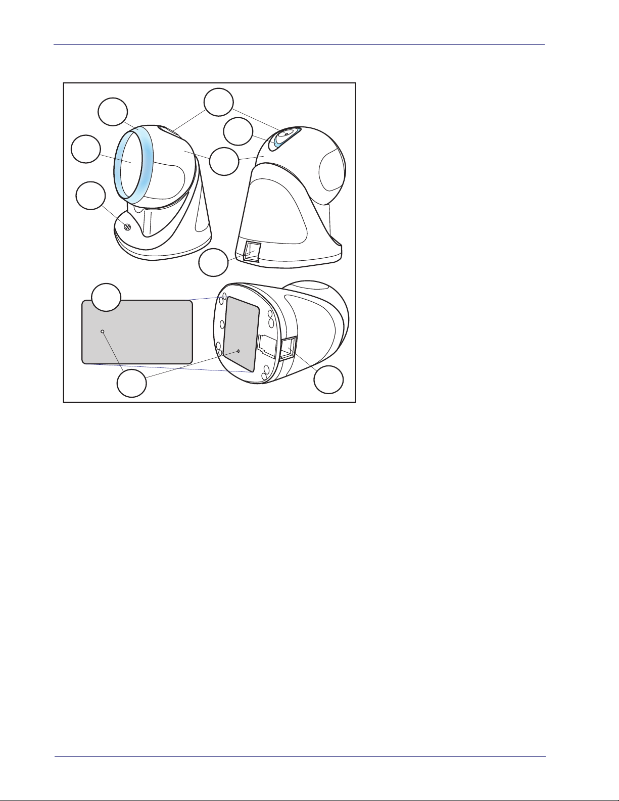
1
Serial Number/Regulatory Label
2
Speaker
3
Scan Window
4
Ring of Light
5
Touch Button
6
Visual Indicator
7
Head
8
Interface / Power Port
9
Bottom Button
Figure 1. Nomenclature and Labeling
Capacitive Touch Button
The Touch Button (also referred to as the trigger) located on the top of the scanner is actuated
by the electrical impulses present in a human fingertip, and is thus a capacitive Touch Button.
Normally, the scanner operates in omnidirectional mode, simultaneously projecting 20 lines
which form a scan pattern; highly useful for capturing bar codes presented from multiple
directions and angles.
When the Touch Button is actuated, the scanner enters single scan line operation, allowing the
scanner to more easily target and read truncated bar codes, or aim at a single label from
amongst multiple bar codes as an ordinary handheld scanner would do. For example, it is
recommended to use single line operation to read the programming bar codes presented in
this manual.
This button can also be used to wake up the scanner when it has gone to sleep.
Bottom Button
The scanner is also equipped with a mechanical button located at the bottom side of its base.
This Bottom Button s protected by a rubber seal and can perform two functions:
1. While using the Aladdin
made, the Bottom Button is used to activate this function.
2. This button is also used to activate the boot loader for firmware upgrade when this
request is made using the Aladdin utility. This is the button used when the Aladdin utility
asks to reset the product by powering up the product while keeping the button pressed.
TM
configuration utility, when a “force device connect” request is
2
Cobalto™ CO5300 Scanner
Page 15

About this Manual
This Product Reference Guide (PRG) is provided for users seeking advanced technical
information, including connection, programming, maintenance and specifications. The Quick
Reference Guide (QRG) and other publications associated with this product are downloadable
free of charge from the website listed on the back cover of this manual.
Typically, units are factory-programmed for the most common terminal and communications
ttings. If you need to modify any programmable settings, custom configuration can be
se
accomplished by scanning the programming bar codes within this guide.
Programming can alternatively be performed using the Datalogic Aladdin™
application which is available from the Datalogic website listed on the back cover of this
manual. This multi-platform utility program allows device configuration using a PC. It
communicates to the device using a serial or USB cable and can also create configuration bar
codes to print.
Overview
Chapter 1, Introduction provides a product overview, unpacking instructions, and cable
connection information.
Chapter 2, Setup presents information about unpacking and setting up the scanner, and
interface configuration bar code
Chapter 3, Configuration Using Bar Codes provides instructions and bar code labels for
customizing your scanner. There are different sect
data formatting, symbology-specific and model-specific features.
Chapter 4, References provides details concerning programmable features.
Appendix A, Appendix A, Technical Specifications lists physical and performance
characteristics, as well as environmental and r
standard cable pin-outs and descriptions of the functions and behaviors of the scanner’s LED
and Speaker indicators.
Appendix B, Appendix B, Standard Defaults references common factory default settings
for scanner features and options.
Appendix C, Appendix C, Sample Bar Codes offers sample bar codes of several common
symbologies.
Appendix D, Appendix D, Keypad includes numeric bar codes to be scanned for certain
parameter settings.
Appendix E, Appendix E, Scancode Tables lists control character emulation information for
Wedge and USB Keyboard interfaces.
About this Manual
Configuration
s and details.
ions for interface types, general features,
egulatory specifications. It also provides
Conventions
The symbols listed below are used in this manual to notify the scanner of key issues or
procedures that must be observed when using the scanner:
Notes contain information necessary for properly diagnosing, repairing and operating the scanner.
NOTE
Product Reference Guide
3
Page 16

Introduction
The CAUTION symbol advises you of actions that could damage equipment or
property.
CAUTION
Technical Support
Datalogic Website Support
The Datalogic website (www.datalogic.com) is the complete source for technical support and
information for Datalogic products. The site offers product suppor
product manuals, product tech notes, software updates, demos, and instructions for returning
products for repair.
Reseller Technical Support
An excellent source for technical assistance and information is an authorized Datalogic
reseller. A reseller is acquainted with specific types of businesses, application software, and
computer systems and can provide individualized assistance.
t, warranty information,
Telephone Technical Support
If you do not have internet or email access, you may contact Datalogic technical support at
(541) 349-8283 or check the back cover of your manual for more contact information.
Current versions of the Product Reference Guide (PRG), Quick Reference Guide (QRG), the
alogic Aladdin™ Configuration application, software/firmware and any additional manuals,
Dat
instruction sheets and utilities for this product can be downloaded from the website listed on
the back cover of this manual. Alternatively, printed copies or product support CDs can be
purchased through your Datalogic reseller.
4
Cobalto™ CO5300 Scanner
Page 17

Unpacking
1
Cable Connector
2
Interface / Power Port
3
Paper clip
Check carefully to ensure the scanner and any cables or accessories ordered are present and
undamaged. If any damage occurred during shipment, contact
KEEP THE PACKAGING. Should the unit ever require service, it should be returned in its original
shipping container.
Setting Up the Scanner
Follow the steps provided in this section to connect and get your scanner up and
communicating with its host:
1. Connect the Interface Cable at the scanner as shown in Figure 1. To disconnect the cable,
insert a paper clip or similar object into the opening shown (item #3).
2. Connect the other end to the Host (see the next section, Connect Host Interface and Figure 2).
Chapter 2
Setup
Technical Support on page 4.
3. Modify Customizing Configuration Settings on page 11 (only if modifications are needed
from factory settings).
Figure 1. Cable Connection/Disconnection at the Scanner
r
1
Product Reference Guide
2
3
5
Page 18

Setup
Connect Host Interface
The scanner kit you ordered to match your interface should provide a compatible cable for your
installation. If this is not so, contact
Depending on the model, the scanner can communicate using the following interfaces:
RS-232 Serial Connection
Turn off power to the terminal/PC and connect the scanner to the terminal/PC serial port via
the RS-232 cable as shown in
Terminal) to supply scanner power, use the approved power supply (AC Adapter). Plug the AC
Adapter barrel connector into the socket on the RS-232 cable connector and the AC Adapter
plug into a standard power outlet.
Technical Support.
Figure 2. If the terminal will not support POT (Power Off the
RS-232 —
host.
RS-232 OPOS —
The scanner can communicate with a standard or Wincor-Nixdorf (W-N) RS-232
This interface is used for OPOS/UPOS/JavaPOS systems.
Keyboard Wedge Connection
The Keyboard Wedge cable has a ‘Y’ connection from the scanner. Connect the female to the
male end from the keyboard and the remaining end at the keyboard port at the terminal/PC.
Keyboard Wedge (KBW) —
data as keystrokes and supports several international keyboards (for the Windows
environment). See
Country Mode on page 35 for a full listing.
When connected using this interface, the host interprets scanned
®
USB Connection
Connect the scanner to a USB port on the terminal/PC using the correct USB cable for the
interface type you ordered.
USB —
types by scanning the appropriate interface type bar codes available in this manual. The
default interface is USB-KBD, or RS-232-STD.
Select to communicate either by USB OEM, USB COM STD, or USB Keyboard interface
6
Cobalto™ CO5300 Scanner
Page 19
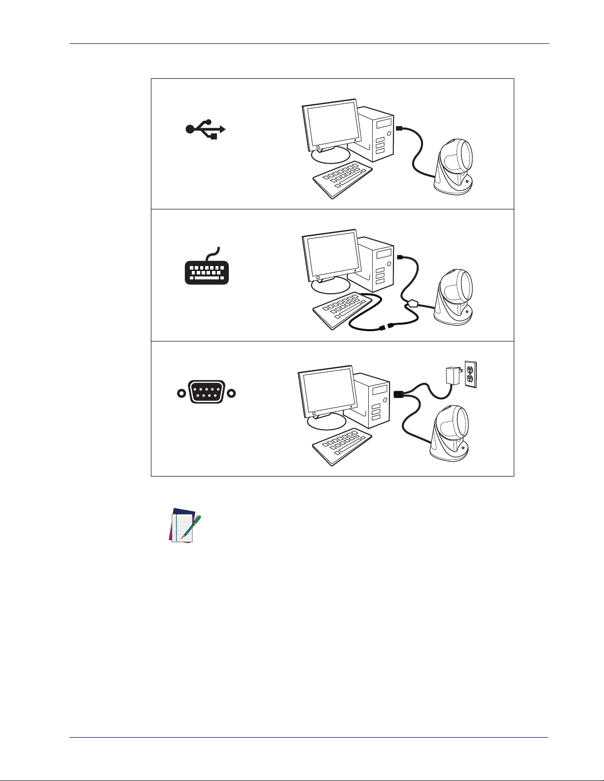
Figure 2. Connection to the Host
USB
Keyboard Wedge
Setting Up the Scanner
RS-232
NOTE
Specific cables are required for connection to different hosts. The connections illustrated in Figure 2 are examples only. Actual connecto
trated, but the steps to connect the scan
ner remain the same.
rs may vary from those illus-
Product Reference Guide
7
Page 20

Setup
Interface Selection
Upon completing the physical connection between the scanner and its host, proceed directly to
Configuring the Interface on page 8 for information and programming for the interface type
the scanner is connected to (for example: RS-232
appropriate bar code in tha section to select your system’s correct interface type.
The scanner, depending upon the model, will support one of the following sets of host
in
terfaces:
USB Models (3.0 full speed)
•USB-KBD
• USB-COM STD
•USB-OEM
•USB-KBD-ALT
• USB-KBD + USB COM
RS-232 / Keyboard Wedge Models
• RS-232 (Standard, Wincor-Nixdorf, OPOS)
• Keyboard Wedge
, Keyboard Wedge, USB, etc.) and scan the
Configuring the Interface
Scan the programming bar code from the following section which selects the appropriate
interface type to match the system the scanner will be connected to. Next, proceed to the
corresponding chapter in this manual (also listed in the table) to configure any desired settings
and features associated with that interface.
Unlike some other programming features and options, interface selections
require that you scan only one programming bar code label. DO NOT scan an
ENTER/EXIT bar code prior to scanning an interface selection bar code.
Some interfaces require the scanner to start in
NOTE
up. If additional scanner configuration is desired while in this state, pull the trigger and hold it for five seconds. The scanner will change to a
programming with bar codes.
the disabled state when powered
state that allows
8
Cobalto™ CO5300 Scanner
Page 21
Interface Selection
Table 3. Available Interfaces
RS-232 FEATURES
RS-232 standard interface
$P,HA12,P
Select RS232-WN
RS-232 for use with OPOS/UPOS/JavaPOS
$P,HA13,P
$P,HA05,P
Select RS232-STD
RS-232 Wincor-Nixdorf
$P,HA13,P
Select RS-232 OPOS
USB Com to simulate RS-232 standard inter-
face
Set RS-232
Interface
Features
starting on
page 19
Select USB-COM-STD
USB-OEM FEATURES
USB-OEM
e used for OPOS/UPOS/JavaPOS)
(can b
a. Download the correct USB Com driver from www.datalogic.com
a
$P,HA45,P
Select USB-OEM
Set USB-
OEM
Interface
Features
starting on
page 43
Product Reference Guide
9
Page 22
Setup
KEYBOARD FEATURES
$P,HA29,P
AT, PS/2 25-286, 30-286, 50, 50Z, 60, 70, 80,
& 95 w/Standard Key Encoding
90
Select KBD-AT
$P,HA11,P
Keyboard Wedge for IBM AT PS2 with standard key encoding but without external keyboard
Select KBD-AT-NK
$P,HA26,P
AT, PS/2 25-286, 30-286, 50, 50Z, 60, 70, 80,
& 95 w/Alternate Key
90
Select KBD-AT-ALT
$P,HA10,P
Select KBD-AT-ALT-NK
USB Keyboard with standard key encoding
$P,HA2B,P
Select USB Alternate Keyboard
USB Keyboard + USB COM
Keyboard Wedge for IBM AT PS2 with alter-
nate key encoding but without external key-
board
$P,HA35,P
Select USB Keyboard
USB Keyboard with alternate key encoding
$P,HA4D,P
Set KEYBOARD
WEDGE
Interface
Features
starting on
page 33
10
Select USB Keyboard + USB COM
Cobalto™ CO5300 Scanner
Page 23

Customizing Configuration Settings
Using the Programming Bar Codes
This manual contains feature descriptions and bar codes which allow you to reconfigure your
scanner. Some programming bar code labels, like Resetting the Product Configuration to
Defaults on page 13, require only the scan of that single label to enact the change. Most of the
programming labels in this manual, however, requir
Mode prior to scanning them. Scan an ENTER/EXIT bar code once to enter Programming
Mode. Once the scanner is in Programming Mode, you can scan a number of parameter
settings before scanning the ENTER/EXIT bar code a second time, which will then accept your
changes, exit Programming Mode and return the scanner to normal operation.
There are some exceptions to the typical programming sequence described
above. Please read the description and setting instructions carefully when
configuring each given programmable feature.
NOTE
Datalogic Aladdin™ Utility
Programming can alternatively be performed using the Datalogic Aladdin™ Configuration
application which is available for free download from the Datalogic website listed on the back
cover of this manual. This multi-platform utility program allows device configuration using a
PC. It communicates to the device using a serial or USB cable and can also create configuration
bar codes to print.
Datalogic Aladdin™ is a multi-platfor
configuration method via the RS-232/USB-COM interface. the Aladdin utility is available on
the CD-ROM provided with your product, and also from the Datalogic website. Aladdin allows
you to program the scanner by selecting configuration commands through a user-friendly
graphical interface running on a PC. These commands are sent to the scanner over the
selected communication interface, or they can be printed as bar codes to be scanned.
Aladdin also provides the ability to perform a soft
the Datalogic Aladdin™ Help On-Line for more details).
m utility program providing a quick and user-friendly
Customizing Configuration Settings
e the scanner to be placed in Programming
ware upgrade for the connected device (see
Product Reference Guide
11
Page 24

Setup
Transmit Software Version
RevA
Interface Settings
The scanner is typically factory-configured with a set of default features standard to the
interface type you ordered. See Interface Selection on page 8.
Global Interface Features, starting on page 17 provides settings configurable by all interface
types. If your installation requir
options through use of the instructions and programming bar codes available in the
appropriate section for your interface.
• RS-232 ONLY Interface, starting on page 19
• RS-232/USB-COM Interfaces, starting on page 23
• Keyboard Interface, starting on page 33
• USB-OEM Interface, starting on page 43
Configuring Other Features
If your installation requires different programming than the standard factory default settings,
the following sections of this manual allow configuration of non-interface-specific settings
you might require:
es you to further customize your scanner, you can select other
Configuration Using Bar Codes —
speaker and LED indicators and other such universal settings.
Reading Parameters —
LED indicators and other universal settings.
Symbologies —
settings allow you to enable/disable symbologies, set label lengths, require check digit, etc.
Includes options concerning the bar code label types (symbologies). These
Reading Parameters include programming for scanning, speaker and
Software Version Transmission
The software version of the device can be transmitted over the RS-232, Keyboard and USB
interfaces by scanning the following label.
General Features includes programming for scanning,
12
Cobalto™ CO5300 Scanner
Page 25
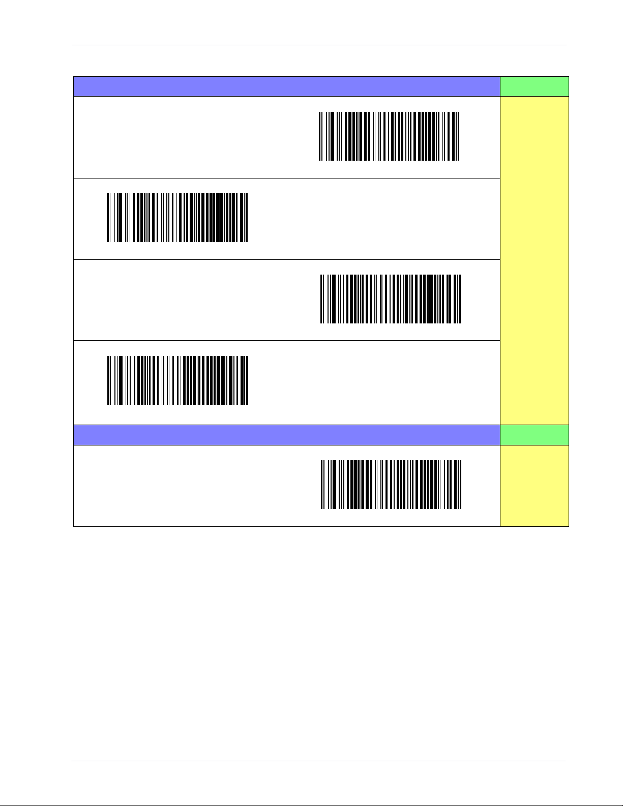
Customizing Configuration Settings
Restore Custom Default Configuration
Restore USA Factory Configuration
Restore EU Factory Configuration
Resetting the Product Configuration to Defaults
If you aren't sure what programming options are in your scanner, or you've changed some
options and want to restore the Custom Default Configuration that may have been saved in
the scanner, scan the Restore Custom Default Configuration bar code below. This will restore
the custom configuration for the
Custom defaults are based on the interface type. Configure the scanner for the
correct interface before scanning this label.
NOTE
If you aren't sure what programming options are in your scanner, or you've changed some
options and want to restore the Factory Configuration, you have two options. You can scan the
Restore USA Factory Configuration bar code or the Restore EU Factory Configuration bar code
below. Both labels restore the scanner configuration to the factory settings including the
terface type. The USA label restores Label IDs to those historically used in the USA. The EU
in
label restores Label IDs to those historically used in Europe. The Label ID sets for USA and EU
are shown in the Label ID section of this manual.
currently active interface.
Scanning either of the “Restore Factory Configuration” commands below will
result in the loss of any custom configuration settings for your device.
CAUTION
The programming section on the following pages lists the factory default settings for each of
the menu commands (indicated by shaded blocks and bold text).
Product Reference Guide
13
Page 26

Setup
NOTES
14
Cobalto™ CO5300 Scanner
Page 27

Configuration Using Bar Codes
This and following sections provide programming bar codes to configure your scanner by
changing the default settings. For details about additional methods of programming, see
Customizing Configuration Settings" on page 11.
"
You must first enable your scanner to read bar codes in order to use this
section. If you have not done this, go to
NOTE
Configuration Parameters
Once the scanner is set up, you can change the default parameters to meet your application
needs. Refer to "
configuration in order to set the default values
The following configuration parameters are divided into logical groups, making it easy to find
the
desired function based on its reference group.
Interface Configuration:
• "RS-232 ONLY Interface" on page 19
• "RS-232/USB-COM Interfaces" on page 23
• "Keyboard Interface" on page 33
• "USB-OEM Interface" on page 43
Resetting the Product Configuration to Defaults" on page 13 for initial
complete the appropriate procedure.
Chapter 3
Setup, starting on page 5
and select the interface for your application.
and
Parameters common to all interface applications:
• "Global Prefix/Suffix" on page 46
Data Format" on page 45 offers advanced configuration options for customization of
• "
scanned data output.
Reading Parameters" on page 57 control various operating modes and indicators
• "
status functioning.
Symbology-specific parameters:
"Symbologies" on page 79 defines options for all symbologies and provides the
programming bar codes necessary for config
Product Reference Guide
uring these features.
15
Page 28

Enter/Exit Programming Mode Configuration Parameters
You must first enable your scanner to read bar codes in order to use this
section. If you have not done this, go to
complete the appropriate procedure.
Setup, starting on page 5
and
NOTE
To program features:
1. Scan the ENTER/EXIT PROGRAMMING bar code, available at the top of each programming page, when applicable.
2. Scan the bar code to set the desired prog
unused bar codes on the page, and possibly the facing page, to ensure that the scanner
reads only the bar code you intend to scan.
3. If additional input param
appropriate characters from the keypad.
Additional information about many features can be found in the “References”
chapter.
NOTE
4. Complete the programming sequence by scanning the ENTER/EXIT PROGRAMMING bar
code to exit Programming Mode.
For more detailed descriptions, programming information and examples for setting selected
figuration items, see
con
If you make a mistake before the last character, scan the CANCEL bar code to
abort an
eters are needed, go to Appendix D, Keypad, and scan the
d not save the entry string. You can then start again at the beginning.
References, starting on page 217.
ramming feature. You may need to cover
16
Cobalto™ CO5300 Scanner
Page 29
Global Interface Features Enter/Exit Programming Mode
DEFAULT
Global Interface Features
The following interface features are configurable by all interface types. To set features specific
to your interface, turn to that section of this manual:
"RS-232 ONLY Interface" on page 19
•
• "RS-232/USB-COM Interfaces" on page 23
• "Keyboard Interface" on page 33
• "USB-OEM Interface" on page 43
Host Commands — Obey/Ignore
This option specifies whether the scanner will obey or ignore host commands. When set to
ignore, the scanner will ignore all host commands except for those necessary for:
• service mode
• flash programming mode
• keeping the interface active
• transmission of labels.
$CIFIH01
Host Commands = Ignore
$CIFIH00
Host Commands = Obey
Product Reference Guide
17
Page 30
Enter/Exit Programming Mode Global Interface Features
USB Suspend Mode
This setting enables/disables the ability of the USB interface to enter suspend mode.
$CUSSE00
USB Suspend Mode = Disable
$CUSSE01
DEFAULT
USB Suspend Mode = Enable
18
Cobalto™ CO5300 Scanner
Page 31

RS-232 Standard Factory Settings Enter/Exit Programming Mode
RS-232 ONLY Interface
Use the programming bar codes in this chapter if modifications to the standard RS-232
interface settings are necessary to meet your system’s requirements. Additional settings
which apply to both the RS-232 and USB interfaces are available in
COM Interfaces
.
RS-232 Standard Factory Settings
Reference Appendix B, Standard Defaults for a listing of standard factory settings.
Baud Rate
Baud rate is the number of bits of data transmitted per second. Set the scanner's baud rate to
match the baud rate setting of the host device. With an improper baud rate setting, data may
not reach the host correctly.
$CR2BA00
Chapter 5, RS-232/USB-
$CR2BA01
Baud Rate = 2400
$CR2BA03
Baud Rate = 9600
Baud Rate = 1200
$CR2BA02
Baud Rate = 4800
Product Reference Guide
19
Page 32

Enter/Exit Programming Mode Stop Bits
DEFAULT
Baud Rate — continued
$CR2BA04
Baud Rate = 19,200
$CR2BA05
Baud Rate = 38,400
$CR2BA06
Baud Rate = 57,600
Stop Bits
$CR2BA07
Baud Rate = 115,200
The stop bit(s) at the end of each transmitted character marks the end of transmission of one
character and prepares the receiving device for the next character in the serial data stream.
The number of stop bits selected (one or two) depends on the number the receiving terminal is
programmed to accommodate. Set the number of stop bits to match host device
requirements.
$CR2ST00
DEFAULT
1 Stop Bit
$CR2ST01
20
2 Stop Bits
Cobalto™ CO5300 Scanner
Page 33

Parity Enter/Exit Programming Mode
Parity
This feature specifies parity required for sending and receiving data. A parity check bit is the
most significant bit of each ASCII coded character. Select the parity type according to host
device requirements.
• Select None when no parity bit is required.
• Select Odd parity and the parity bit value is set to 0 or 1, based on data, to ensure that an
odd nu
• Select Even parity and the parity bit value is set to 0 or 1, based on data, to ensure that
an
mber of 1 bits are contained in the coded character.
even number of 1 bits are contained in the coded character.
DEFAULT
$CR2PA01
Parity = Even
$CR2PA00
Parity = None
$CR2PA02
Parity = Odd
Product Reference Guide
21
Page 34

Enter/Exit Programming Mode Handshaking Control
Handshaking Control
The data interface consists of an RS-232 port designed to operate either with or without the
hardware handshaking lines, Request to Send (RTS), and Clear to Send (CTS). Handshaking
Control includes the following options:
• RTS — RTS is asserted during t
• RTS/CTS — RTS is asserted during tran
• RTS/XON/XOFF — RTS is asserted during t
gate transmissions.
• RTS On/CTS — RTS is always ass
• RTS/CTS Scan Control — RTS is asserted during transmissions.
and controls enable and disable state of scanner.
ransmissions. CTS is ignored.
smissions. CTS gates transmissions.
ransmissions. CTS is ignored. XON and XOFF
erted. CTS gates transmissions.
CTS gates transmissions
DEFAULT
$CR2HC01
Handshaking Control = RTS/CTS
$CR2HC03
Handshaking Control = RTS On/CTS
$CR2HC00
Handshaking Control = RTS
$CR2HC02
Handshaking Control = RTS/XON/XOFF
$CR2HC04
22
Handshaking Control = RTS/CTS Scan Control
Cobalto™ CO5300 Scanner
Page 35

Standard Factory Settings Enter/Exit Programming Mode
00 = No Intercharacter Delay
RS-232/USB-COM Interfaces
The programming bar codes in this chapter allow modifications to the standard RS-232 and
USB-Com interfaces.
Standard Factory Settings
Reference Appendix B, Standard Defaults for a listing of standard factory settings.
Intercharacter Delay
This parameter specifies the intercharacter delay between the end of one character and the
beginning of the next. The delay can be set within a range of zero (0) to 990 milliseconds in
10ms increments. A setting of zero specifies no delay. See
page 232
for more detailed programming instructions.
"Label ID: Pre-loaded Sets" on
$CR2IC00
$CR2IC
Select Intercharacter Delay Setting
Make a mistake? Scan the CANCEL bar code to abort
an
d not save the entry string. You can then start
again at the beginning.
DEFAULT
Intercharacter Delay = No Delay
To configure this feature, scan the ENTER/EXIT bar
above, then the bar code at left followed by dig-
code
its from the Alphanumeric c
Keypad
by scanning the ENTER/EXIT bar code again.
representing your desired character(s). End
haracters in Appendix D,
~
CANCEL
Product Reference Guide
23
Page 36

Enter/Exit Programming Mode Beep On ASCII BEL
DEFAULT
Beep On ASCII BEL
When this parameter is enabled, the scanner issues a beep when a <BEL> character is
detected on the RS-232 serial line. <BEL> is issued to gain a user's attention to an illegal entry
or other important event.
$CR2BB00
Beep On ASCII BEL = Disable
Beep On Not on File
This option enables/disables the action of the scanner to sound a three beep sequence upon
receiving a Not-On-File (NOF) host command.
$CBPNF00
DEFAULT
$CR2BB01
Beep On ASCII BEL = Enable
24
Beep On Not On File = Disable
$CBPNF01
Beep On Not On File = Enable
Cobalto™ CO5300 Scanner
Page 37

ACK NAK Options Enter/Exit Programming Mode
ACK NAK Options
This enables/disables the ability of the scanner to support the RS-232 ACK/NAK protocol.
When configured, the scanner and/or host sends an “ACK” when it receives data properly, and
sends “NAK” when the data is in error.
Options are:
•Disable
• Enable for label transmission — The scanner expects an ACK/NAK response from the
host when a label is sent.
• Enable for host-command acknowledge — The scanner will respond with ACK/NAK
when the host sends a command.
• Enable for label transmission and host-command acknowledge
$CR2AE00
DEFAULT
ACK/NAK Protocol = Disable ACK/NAK
$CR2AE01
ACK/NAK Protocol = Enable for label transmission
$CR2AE03
ACK/NAK Protocol = Enable for label transmission and
host-command acknowledge
$CR2AE02
ACK/NAK Protocol = Enable for host-command
acknowledge
Product Reference Guide
25
Page 38

Enter/Exit Programming Mode ACK NAK Options
0x06 ‘ACK’ Character
0x15 ‘NAK’ Character
ACK Character
This setting specifies an ASCII character or hex value to be used as the ACK character. ASCII
characters or any hex value from 0 to 0xFF can be selected. See
page 220
Select ACK Character Setting
for more detailed programming instructions.
Setting to previously defined characters such as XON, XOFF, or host
commands conflicts with normal operation of these characters. 8-bit
data is not recognized when the option
NOTE
$CR2AC
Data Bits.
"ACK Character" on
Stop Bits
has been set as 7
DEFAULT
NAK Character
This setting specifies an ASCII character or hex value to be used as the NAK character. ASCII
characters or any hex value from 0 to 0xFF can be selected. See
page 221
Select NAK Character Setting
for more detailed programming instructions.
Setting to previously defined characters such as XON, XOFF, or host
commands conflicts with normal operation of these characters. 8-bit
data is not recognized when the option
NOTE
$CR2NA
Data Bits.
DEFAULT
"NAK Character" on
Stop Bits
has been set as 7
26
Cobalto™ CO5300 Scanner
Page 39

ACK NAK Options Enter/Exit Programming Mode
DEFAULT
01 ACK NAK Timeout value is 200ms
ACK NAK Timeout Value
This option specifies the amount of time the scanner waits for an ACK character from the host
following label transmission. The selectable timeout range is 200 milliseconds to 15,000ms (15
seconds) in 200ms increments. A selection of 0 disables the timeout. See
Value" on page 222
for more detailed programming instructions.
"ACK NAK Timeout
$CR2AT
Select ACK NAK Timeout Value Setting
Make a mistake? Scan the CANCEL bar code
and not save the entry string. You can then start
again at the beginning.
to abort
To configure this feature, scan the ENTER/EXIT bar
e above, then the bar code at left followed by dig-
cod
its from the Alphanumeric characters in
Keypad
by scanning the ENTER/EXIT bar code again.
representing your desired character(s). End
~
CANCEL
Appendix D,
Product Reference Guide
27
Page 40

Enter/Exit Programming Mode ACK NAK Options
003 = 3 Retries
ACK NAK Retry Count
This feature specifies the number of times the scanner retries a label transmission due to a
retry condition. The selectable range is from 1 to 254 retries. A selection of 0 disables the
count, and a selection of 255 specifies unlimited retries. See
page 223
for more detailed programming instructions.
"ACK NAK Retry Count" on
$CR2AR
Select ACK NAK Retry Count Setting
Make a mistake? Scan the CANCEL bar code
and not save the entry string. You can then start
again at the beginning.
to abort
DEFAULT
To configure this feature, scan the ENTER/EXIT bar
e above, then the bar code at left followed by dig-
cod
its from the Alphanumeric characters in
Keypad
by scanning the ENTER/EXIT bar code again.
representing your desired character(s). End
~
CANCEL
Appendix D,
28
Cobalto™ CO5300 Scanner
Page 41

ACK NAK Options Enter/Exit Programming Mode
ACK NAK Error Handling
This feature specifies the method the scanner uses to handle receive errors detected while
waiting for an ACK character from the host.
Options are:
• Ignore errors detected
• Process error as valid ACK character
• Process error as valid NAK character
DEFAULT
$CR2EH01
ACK NAK Error Handling = Process Error as Valid ACK
ter
Charac
$CR2EH00
ACK NAK Error Handling = Ignore Errors Detected
$CR2EH02
ACK NAK Error Handling = Process Error as
Valid NAK Character
Product Reference Guide
29
Page 42

Enter/Exit Programming Mode Indicate Transmission Failure
0x44 = Disable Character is ‘D’
Indicate Transmission Failure
This option enables/disables the scanner’s ability to sound an error beep to indicate a
transmission failure while in ACK/NAK mode
$CR2TF01
.
$CR2TF00
Indicate Transmission Failure = Disable Indication
DEFAULT
Indicate Transmission Fail
Disable Character
Specifies the value of the RS-232 host command used to disable the scanner.
ASCII characters or any hex value from 0
page 224
Select Disable Character Setting
for more detailed programming instructions.
NOTE
$CR2DC
ure = Enable Indication
to 0xFF can be selected. See "Disable Character" on
Setting to previously defined characters such as XON, XOFF, or host
commands conflicts with normal operation of these characters.
30
DEFAULT
Cobalto™ CO5300 Scanner
Page 43

Enable Character Enter/Exit Programming Mode
0x45 = Enable Character is ‘E’
Enable Character
Specifies the value of the RS-232 host command used to enable the scanner.
ASCII characters or any hex value from 0 to 0xFF can be
page 225
Select Enable Character Setting
for more detailed programming instructions
Setting to previously defined characters such as XON, XOFF, or host
commands conflicts with normal operation of these characters.
NOTE
$CR2EC
selected. See "Enable Character" on
.
DEFAULT
Product Reference Guide
31
Page 44

Enter/Exit Programming Mode Enable Character
NOTES
32
Cobalto™ CO5300 Scanner
Page 45

Country Mode Enter/Exit Programming Mode
Keyboard Interface
Use the programming bar codes in this chapter to select options for USB Keyboard and Wedge
Interfaces. Reference
settings. Information about control character emulat
is listed in
Country Mode
This feature specifies the country/language supported by the keyboard.
The Country Mode setting is ignored if the interface uses alternate key encoding.
DEFAULT
$CKBCO01
Appendix E, Scancode Tables.
Appendix B, Standard Defaults for a listing of standard factory
ion which applies to keyboard interfaces
$CKBCO00
Country Mode = U.S.
Country Mode = Belgium
$CKBCO11
Country Mode = Croatia
$CKBCO02
Country Mode = Britain
$CKBCO0E
Country Mode = Czech Republic
Product Reference Guide
33
Page 46

Enter/Exit Programming Mode Country Mode
Country Mode — continued
$CKBCO03
Country Mode = Denmark
$CKBCO04
Country Mode = France
$CKBCO05
Country Mode = Germany
$CKBCO0D
$CKBCO06
Country Mode = Italy
$CKBCO07
Country Mode = Norway
Country Mode = Hungary
$CKBCO0C
Country Mode = Japanese 106-key
$CKBCO12
34
Country Mode = Poland
Cobalto™ CO5300 Scanner
Page 47

Country Mode Enter/Exit Programming Mode
Country Mode — continued
$CKBCO10
Country Mode = Romania
$CKBCO09
Country Mode = Spain
$CKBCO08
Country Mode = Portugal
$CKBCO0F
Country Mode = Slovakia
$CKBCO0A
Country Mode = Sweden
$CKBCO0B
Country Mode = Switzerland
$CKBCO13
Country Mode = French Canadian
$CKBCO14
Country Mode = Lithuania
Product Reference Guide
35
Page 48

Enter/Exit Programming Mode Caps Lock State
Caps Lock State
This option specifies the format in which the scanner sends character data. This applies to
Keyboard Wedge interfaces.
This does not apply to USB Keyboard.
This does not apply when an alternate key encoding keyboard is selected.
Caps Lock State = Caps Lock ON
Numlock
DEFAULT
$CKBCL01
$CKBCL00
Caps Lock State = Caps Lock OFF
$CKBCL02
Caps Lock State = AUTO Caps Lock Enable
36
This option specifies the setting of the Numbers Lock (Numlock) key while in Keyboard Wedge
interface. This only applies to alternate key encoding interfaces.
Keyboard.
It does not apply to USB
$CKBNL00
DEFAULT
Numlock = Numlock key unchanged
$CKBNL01
Numlock = Numlock key toggled
Cobalto™ CO5300 Scanner
Page 49

Keyboard Numeric Keypad Enter/Exit Programming Mode
Keyboard Numeric Keypad
This feature specifies if numeric characters will be sent using the standard keys or the numeric
keypad
.
DEFAULT
$CKBKP01
Keyboard Numeric Keypad = Numeric Keypad
$CKBKP00
Keyboard Numeric Keypad = Standard Keys
Product Reference Guide
37
Page 50

Enter/Exit Programming Mode Keyboard Send Control Characters
Keyboard Send Control Characters
This feature is used by the Keyboard Wedge and USB Keyboard interfaces. It specifies how the
scanner transmits ASCII control characters to the host. Reference
Tables
Options are as follows:
for more information about control characters.
Appendix E, Scancode
Send Ctrl+Key —
Ctrl+Key. Special keys are available in the range from 81H to A1.
Send Ctrl+Shift+Key —
format Ctrl+Shift+Keys.
Send Special Function Key —
function key mapping table (see Scancode
that are not in the normal ASCII set. A unique set is provided for each available scancode set.
DEFAULT
$CKBSC01
Keyboard Send Control Characte
ASCII characters from 00H to 0x1FH inclusive are transmitted in the format
The behavior is the same as above, but control keys are sent in the
Send characters between 00H and 1FH according to the special
Table 28 on page 273). This is used to send keys
$CKBSC00
Keyboard Send Control Characters = Send Ctrl+Key
rs = Send Ctrl+Shift+Key
$CKBSC02
38
Keyboard Send Control Characters = Send Special
Function Key :
Cobalto™ CO5300 Scanner
Page 51

Wedge Quiet Interval Enter/Exit Programming Mode
10 = Quiet Interval of 100 ms
Wedge Quiet Interval
This option specifies the amount of time to look for keyboard activity before the scanner
breaks the keyboard connection in order to transmit data to host. The selectable range for this
feature is from 0 to 990ms in 10ms increments. See
more detailed programming instructions.
This feature applies ONLY to the Keyboard Wedge interface.
NOTE
"Wedge Quiet Interval" on page 226 for
$CKBQI
Select Wedge Quiet Interval Setting
Make a mistake? Scan the CANCEL bar code to abort
and not save the entry string. You can then start
again at the beginning.
DEFAULT
To configure this feature, scan the ENTER/EXIT bar code
above, then the bar code at left followed by digits from the
Alphanumeric characters in
senting your desired character(s). End by scanning the ENTER/
EXIT bar c
ode again.
Appendix D, Keypad
~
CANCEL
repre-
Product Reference Guide
39
Page 52

Enter/Exit Programming Mode Intercharacter Delay
00 = No Intercharacter Delay
Intercharacter Delay
This parameter specifies the intercharacter delay between the end of one character and the
beginning of the next. The delay can be set within a range of zero (0) to 990 milliseconds in
10ms increments. A setting of zero specifies no delay. See
page 227
for more detailed programming instructions.
Intercharacter Delay = No Delay
"Intercharacter Delay" on
$CR21C00
$CR21C
Select Intercharacter Delay Setting
Make a mistake? Scan the CANCEL bar code to abort
and not save the entry string. You can then start
again at the beginning.
DEFAULT
To configure this feature, scan the ENTER/EXIT bar code
above, then the bar code at left followed by digits from the
Alphanumeric characters in
senting your desired character(s). End by scanning the ENTER/
EXIT bar c
ode again.
Appendix D, Keypad
~
CANCEL
repre-
40
Cobalto™ CO5300 Scanner
Page 53

Intercode Delay Enter/Exit Programming Mode
DEFAULT
00 = No Wedge Intercode Delay
Intercode Delay
Specifies the delay between labels transmitted to the host for this interface. The selectable
range for this feature is from 0 to 99 seconds. See
detailed programming instructions.
"Intercode Delay" on page 228 for more
$CKBID
Set Intercode Delay
Make a mistake? Scan the CANCEL bar code to abort
and not save the entry string. You can then start
again at the beginning.
To configure this feature, scan the ENTER/EXIT bar code
above, then the bar code at left followed by digits from the
Alphanumeric characters in
senting your desired character(s). End by scanning the ENTER/
EXIT bar c
ode again.
Appendix D, Keypad
~
CANCEL
repre-
Product Reference Guide
41
Page 54

Enter/Exit Programming Mode USB Keyboard Speed
USB Keyboard Speed
This option specifies the USB poll rate for a USB Keyboard.
This feature applies ONLY to the USB Keyboard interface.
NOTE
$CKBSP01
DEFAULT
USB Keyboard Speed = 1ms
$CKBSP02
USB Keyboard Speed = 2ms
$CKBSP03
$CKBSP05
USB Keyboard Speed = 5ms
$CKBSP0A
USB Keyboard Speed = 10ms
USB Keyboard Speed = 3ms
$CKBSP07
USB Keyboard Speed = 7ms
42
Cobalto™ CO5300 Scanner
Page 55

USB-OEM Interface
Introduction
Feature settings for USB interfaces differ depending upon which host type the scanner will be
connected with. Use the feature settings in this chapter to specifically configure for the USBOEM interface. Other USB interfaces are included in the appropriate chapter for their host
type.
Standard Factory Settings
Reference Appendix B, Standard Defaults for a listing of standard factory settings.
Product Reference Guide
43
Page 56

Enter/Exit Programming Mode USB-OEM Device Usage
DEFAULT
DEFAULT
USB-OEM Device Usage
The USB-OEM protocol allows for the scanner to be identified as one of two different types of
bar code scanners. Depending on what other scanners you may already have connected to a
USB-OEM POS, you may need to change this setting to enable all devices to communicate.
Options are:
• Table Top Scanner
• Handheld Scanner
It may be necessary to switch device usage when connecting two
scanners of the same type to a POS system.
NOTE
$CIBUT00
USB-OEM Device Usage = Table Top Scanner
$CIBUT01
USB-OEM Device Usage = Handheld Scanner
USB-OEM Interface Options
This setting provides for an interface specific control mechanism.
Options are:
• Obey — Obey Scanner Configuration Host Commands
• Ignore — Ignore Scanner Con
$CIFO102
USB-OEM Interface Options = Ignore
figuration Host Commands
$CIFO101
USB-OEM Interface Options = Obey
44
Cobalto™ CO5300 Scanner
Page 57

Data Format
GLOBAL PREFIX/SUFFIX on page 46
GLOBAL AIM ID on page 47
LABEL ID starting on page 48
•Label ID: Pre-loaded Sets
•Label ID: Set Individually Per Symbology
•Label ID Control
•Label ID Symbology Selection
CASE CONVERSION on page 56
CASE CONVERSION on page 56
CHARACTER CONVERSION on page 56
The features in this chapter can be used to build specific user-defined data into a message
string. See
features.
"References" starting on page 217 for more detailed instructions on setting these
Product Reference Guide
45
Page 58

Enter/Exit Programming Mode Global Prefix/Suffix
No Global Prefix
Global Suffix = 0x0D(CR)
Global Prefix/Suffix
Up to 20 ASCII characters may be added as a prefix (in a position before the bar code data) and/
or as a suffix (in a position following the bar code data). See
page 229 for more detailed programming instructions.
"Global Prefix/Suffix" on
To configure this feature, scan the ENTER/EXIT bar code above,
then the bar code at left followed by digits from the Alphanumeric characters in
desired character(s). End by scanning the ENTER/EXIT bar code
ain.
ag
Make a mistake? Scan the CANCEL bar code to abort
and not save the entry string. You can then start again
at the beginning.
Appendix D, Keypad
$CLFSU
Set Global Suffix
representing your
DEFAULT
$CLFPR
Set Global Prefix
To configure this feature, scan the ENTER/EXIT bar code above,
then the bar code at left followed by digits from the Alphanumeric characters in
desired character(s). End by scanning the ENTER/EXIT bar code
again.
Appendix D, Keypad
~
CANCEL
representing your
46
Cobalto™ CO5300 Scanner
Page 59

Global AIM ID Enter/Exit Programming Mode
DEFAULT
Global AIM ID
This feature enables/disables addition of AIM IDs for all symbology
types.
NOTE
AIM label identifiers (as opposed to custom characters you select yourself as with label
identifiers) can be included with scanned bar code data. See
more detailed programming instructions.
DEFAULT
$CAIEN01
"Global AIM ID" on page 231 for
$CAIEN00
Global AIM ID = Disable
Global AIM ID = Enable
GS1-128 AIM ID
If Global AIM ID is disabled, the AIM ID for GS1-128 can be enabled/disabled independently.
The AIM ID for GS1-128 is a ]C1, ]C2 or ]C3.
AIM IDs for other symbologies can be enabled/d
Customer Support for assistance.
$CU8AI01
GS1-128 AIM ID = Enable
isabled independently as well. Contact
$CU8AI00
GS1-128 AIM ID = Disable
Product Reference Guide
47
Page 60

Enter/Exit Programming Mode Label ID
Label ID
A Label ID is a customizable code of up to three ASCII characters (each can be one of hex 0x010xFF), used to identify a bar code (symbology) type. It can be appended previous to or following
the transmitted bar code data depending upon how this option is enabled. This feature
provides options for configuring custom Label IDs as a pre-loaded set (see
loaded Sets"
Symbology"
standard label identifier for ALL symbology types, see the previous feature
page 47.
on page 48) or individually per symbology (see "Label ID: Set Individually Per
on page 49). If you wish to program the scanner to always include an industry
Label ID: Pre-loaded Sets
The scanner supports two pre-loaded sets of Label IDs. shows the USA set and the EU set.
"Label ID: Pre-loaded Sets" on page 232 for more information concerning the pre-loaded
See
sets that are provided.
When changing from one Label ID set to another, all other scanner configuration settings, including the host i
factory defaults. Any custom configuration or custom defaults will be lost.
CAUTION
nterface type, will be erased and set to the
"Label ID: Pre-
"Global AIM ID" on
DEFAULT
$Ae
Label ID Pre-loaded Set = EU Set
$AE
Label ID Pre-loaded Set = USA Set
48
Cobalto™ CO5300 Scanner
Page 61

Label ID Enter/Exit Programming Mode
Label ID: Set Individually Per Symbology
This feature configures a Label ID individually for a single symbology.
This setting requires the scanning of bar codes from multiple sections. See
page 234 for more detailed programming instructions.
"Label ID: Set Individually Per Symbology"
on
NOTE
Label ID Control
This option controls whether a Label ID is disabled, or sent as a prefix or suffix for a given
symbology type.
$CIDCO00
DEFAULT
Label ID Transmission = Disable
$CIDCO01
Label ID Transmission = Enable as Prefix
~
CANCEL
$CIDCO02
Label ID Transmission = Enable as Suffix
Make a mistake? Scan the CANCEL bar code to abort
and
not save the entry string. You can then start again
at the beginning.
Product Reference Guide
49
Page 62

Enter/Exit Programming Mode Label ID
Label ID Symbology Selection
This option selects the symbology for which a Label ID is to be configured. See "Label ID: Set
Individually Per Symbology"
$CA2ID
Set UPC-A/P2 Label ID Character(s)
on page 234
for full instructions.
$CABID
Set UPC-A Label ID Character(s)
$CA5ID
$CEBID
Set UPC-E Label ID Character(s)
$CE5ID
Set UPC-E/P5 Label ID Character(s)
Set UPC-A/P5 Label ID Character(s)
$CE2ID
Set UPC-E/P2 Label ID Character(s)
50
Cobalto™ CO5300 Scanner
Page 63

Label ID Enter/Exit Programming Mode
Label ID Symbology Selection — continued
$C3BID
Set EAN 13 Label ID Character(s)
$C32ID
Set EAN 13/P2 Label ID Character(s)
$C35ID
Set EAN 13/P5 Label ID Character(s)
$C8BID
Set EAN 8 Label ID Character(s)
$C85ID
Set EAN 8/P5 Label ID Character(s)
$C82ID
Set EAN 8/P2 Label ID Character(s)
Product Reference Guide
51
Page 64

Enter/Exit Programming Mode Label ID
Label ID Symbology Selection — continued
$C4BID
Set GS1 DataBar Omnidirectional Label ID Character(s)
$CXBID
Set GS1 DataBar Expanded Label ID Character(s)
$CLBID
Set GS1 DataBar Limited Label ID Character(s)
$CC3ID
Set Code 39 Label ID Character(s)
$CCCID
Set Code 39 CIP Label ID Character(s)
$CP3ID
Set Code 32 Label ID Character(s)
52
Cobalto™ CO5300 Scanner
Page 65

Label ID Enter/Exit Programming Mode
Label ID Symbology Selection — continued
$CC8ID
Set Code 128 Label ID Character(s)
$CU8ID
Set GS1-128 Label ID Character(s)
$CI2ID
Set Interleaved 2 of 5 Label ID Character(s)
$CD2ID
Set Datalogic 2 of 5 CIP HR Label ID Character(s)
$CACID
$CHRID
Set Interleaved 2 of 5 CIP HR Label ID Character(s)
$CCBID
Set Codabar Label ID Character(s)
Set ABC Codabar Label ID Character(s)
Product Reference Guide
53
Page 66

Enter/Exit Programming Mode Label ID
Label ID Symbology Selection — continued
$CC1ID
Set Code 11 Label ID Character(s)
$CS2ID
Set Standard 2 of 5 Label ID Character(s)
$CU2ID
Set Industrial 2 of 5 Label ID Character(s)
$CINID
$CIAID
Set IATA Label ID Character(s)
$CMSID
Set MSI Label ID Character(s)
Set ISSN Label ID Character(s)
$CI8ID
Set Concatenated ISBT 128 Label ID Character(s)
$CC9ID
54
Set Code 93 Label ID Character(s)
Cobalto™ CO5300 Scanner
Page 67

Label ID Enter/Exit Programming Mode
Label ID Symbology Selection — continued
$CCFID
Set Codablock F Label ID Character(s)
$CCRID
Set Code 4 Label ID Character(s)
$CCC5ID
Set Code 5 Label ID Character(s)
$CF2ID
$CISID
Set ISBN Label ID Character(s)
Set Follett 2 of 5 Label ID Character(s)
Set Concatenated ISBT Label ID Character(s)
Product Reference Guide
55
Page 68

Enter/Exit Programming Mode Case Conversion
0xFFFFFFFFFFFFFFFF(N
o character conversion)
Case Conversion
This feature allows conversion of the case of all alphabetic characters to upper or lower case.
Case conversion affects ONLY scanned bar code data, and does not
affect Label ID, Prefix, Suffix, or other appended data.
NOTE
$CLFCA00
DEFAULT
Case Conversion = Disable (no case conversion)
$CLFCA01
Case Conversion = Convert to upper case
$CLFCA02
Character Conversion
Character conversion is an eight byte configuration item. The eight bytes are 4 character pairs
represented in hexadecimal ASCII values. The first character in the pair is the character that
will be converted. The second character in the pair is the character to convert to. If the
character to convert in a pair is FF, then no conversion is done. See
on page 236 for more detailed programming instructions.
DEFAULT
Case Conversion = Convert to lower case
"Character Conversion"
$CLFCH
Configure Character Conversion
56
Cobalto™ CO5300 Scanner
Page 69

Reading Parameters
DOUBLE READ TIMEOUT on page 58
LABEL GONE TIMEOUT on page 60
TIMEOUT: ENTER LOW POWER STATE on
page 61
TIMEOUT: ENTER STANDBY STATE on page
63
SELECT AUDIO JINGLE FOR POWER-UP EVENT on
page 68
SELECT AUDIO JINGLE FOR GOOD READ EVENT
on page 70
GOOD READ: WHEN TO INDICATE on page 73
GOOD READ BEEP TYPE on page 74
TIMEOUT: LASER OFF AFTER SINGLE LINE
S
CAN on page 65
GOOD READ BEEP FREQUENCY on page 74
TOUCH BUTTON OPTION on page 66 GOOD READ SPEAKER VOLUME on page 75
LED AND SPEAKER INDICATORS on page 66 GOOD READ BEEP LENGTH on page 76
POWER ON ALERT on page 66 GOOD READ LED DURATION on page 77
AUDIO JINGLE ENABLE on page 67 SCAN MODES on page 78
Product Reference Guide
57
Page 70

Enter/Exit Programming Mode Double Read Timeout
Double Read Timeout
To prevent a double read of the same label, the Double Read Timeout sets the minimum time
allowed between reads of labels of the same symbology and data. If the unit reads a label and
sees the same label again within the Double Read Timeout, the second read of the label will be
ignored. Double Read Timeout does not apply to scan modes that require a trigger pull for each
label that is read.
$CSNDR14
Double Read Timeout = 0.2 Second
$CSNDR28
$CSNDR0A
Double Read Timeout = 0.1 Second
$CSNDR1E
Double Read Timeout = 0.3 Second
58
Double Read Timeout = 0.4 Second
Cobalto™ CO5300 Scanner
Page 71

Double Read Timeout Enter/Exit Programming Mode
Double Read Timeout — continued
$CSNDR32
Double Read Timeout = 0.5 Second
$CSNDR3C
Double Read Timeout = 0.6 Second
$CSNDR50
Double Read Timeout = 0.8 Second
DEFAULT
$CSNDR46
Double Read Timeout = 0.7 Second
$CSNDR5A
Double Read Timeout = 0.9 Second
$CSNDR64
Double Read Timeout = 1 Second
Product Reference Guide
59
Page 72

Enter/Exit Programming Mode Label Gone Timeout
016 = Timeout of 160 ms
Label Gone Timeout
This feature sets the time after the last label segment is seen before the scanner prepares for
a new label. The timeout can be set within a range of 10 milliseconds to 2,550 milliseconds
(2.55 seconds) in 10ms increments. Label Gone Timeout does not apply to scan modes that
require a trigger pull for each label that is read. See
more detailed programming instructions.
Label Gone Timeout on page 237 for
$CSNLG
Select Label Gone Timeout Setting
Make a mistake? Scan the CANCEL bar code
and not save the entry string. You can then start
again at the beginning.
to abort
DEFAULT
To configure this feature, scan the ENTER/EXIT bar
e above, then the bar code at left followed by dig-
cod
its from the Alphanumeric characters in
Keypad
by scanning the ENTER/EXIT bar code again.
representing your desired character(s). End
~
CANCEL
Appendix D,
60
Cobalto™ CO5300 Scanner
Page 73

Timeout: Enter Low Power State Enter/Exit Programming Mode
DEFAULT
Timeout: Enter Low Power State
Specifies the Low Power timeout in minutes.
Upon having been inactive for this period of
where it is running at a limited speed, but is still able to decode.
When this feature is set as Disabled, the scanner will never enter this state.
NOTE
To exit this state, either press the button on the top of the scanner or read a label.
time, the scanner will enter a Low Power state
If the feature
will not trigger single line scanning and the
power state and standby state.
NOTE
$CSMTO01
Enter Low Power Timeout = 1 Minute
Touch Button Option
Enter Low Power Timeout = Disabled
Enter Low Power Timeout = 2 Minutes
has been set to “Disabled,” the button
scanner will never enter low
$CSMTO00
$CSMTO02
$CSMTO03
Enter Low Power Timeout = 3 Minutes
$CSMTO05
Enter Low Power Timeout = 5 Minutes
Product Reference Guide
61
Page 74

Enter/Exit Programming Mode Timeout: Enter Low Power State
Timeout: Enter Low Power State — continued
$CSMTO07
Enter Low Power Timeout = 7 Minutes
$CSMTO0F
Enter Low Power Timeout = 15 Minutes
$CSMTO1E
$CSMTO0A
Enter Low Power Timeout = 10 Minutes
$CSMTO14
Enter Low Power Timeout = 20 Minutes
62
Enter Low Power Timeout = 30 Minutes
$CSMTO5A
Enter Low Power Timeout = 90 Minutes
$CSMTO3C
Enter Low Power Timeout = 60 Minutes
Cobalto™ CO5300 Scanner
Page 75

Timeout: Enter Standby State Enter/Exit Programming Mode
DEFAULT
Timeout: Enter Standby State
Specifies the standby timeout in minutes.
Upon having been in Low Power state (see
enter a Standby state where the laser and motor are
decode a label.
When this feature is set as Disabled, the scanner will never enter this state.
The standby timer starts only after
If you wish the scanner motor and laser to c
NOTE
To exit this state, press the button on the top of the scanner.
you must be sure that the timeout periods for low power and standby total 10
minutes.
page 61) for this period of time, the scanner will
turned off and the scanner is not able to
the low power timeout has elapsed.
ompletely power off after 10 minutes,
If the feature
will not trigger single line scanning and the
power state and standby state.
NOTE
$CSBTO01
Enter Standby Timeout = 1 Minute
Touch Button Option
Enter Standby Timeout = Disabled
Enter Standby Timeout = 2 Minutes
has been set to “Disabled,” the button
scanner will never enter low
$CSBTO00
$CSBTO02
$CSBTO03
Enter Standby Timeout = 3 Minutes
$CSBTO05
Enter Standby Timeout = 5 Minutes
Product Reference Guide
63
Page 76

Enter/Exit Programming Mode Timeout: Enter Standby State
Timeout: Enter Standby State — continued
$CSBTO07
Enter Standby Timeout = 7 Minutes
$CSBTO0F
Enter Standby Timeout = 15 Minutes
$CSBTO1E
$CSBTO0A
Enter Standby Timeout = 10 Minutes
$CSBTO14
Enter Standby Timeout = 20 Minutes
64
Enter Standby Timeout = 30 Minutes
$CSBTO5A
Enter Standby Timeout = 90 Minutes
$CSBTO3C
Enter Standby Timeout = 60 Minutes
Cobalto™ CO5300 Scanner
Page 77

Timeout: Laser Off After Single Line Scan Enter/Exit Programming Mode
DEFAULT
Timeout: Laser Off After Single Line Scan
As described earlier (see Capacitive Touch Button on page 2), pressing the top button can
cause the scanner to enter single scan line operation, allowing the scanner to more easily
target and read truncated bar codes, or aim at a single label fr
This timeout defines the duration of time befor
(trigger) is released.
e the laser is turned off after the button
om amongst multiple bar codes.
$CLOTM01
Laser Off After Single Line Timeout = Off after
1 Second
$CLOTM03
$CLOTM00
Laser Off After Single Line Timeout = Don’t turn off
the Laser
$CLOTM02
Laser Off After Single Line Timeout = Off after
2 Se
conds
Laser Off After Single Line Timeout = Off after
3 Second
$CLOTM08
Laser Off After Single Line Timeout = Off after
8 Second
s
$CLOTM05
Laser Off After Single Line Timeout = Off after
conds
5 Se
s
Product Reference Guide
65
Page 78

Enter/Exit Programming Mode Touch Button Option
Touch Button Option
The capacitive touch button can optionally be disabled so that the scanner will not generate a
single line when the button is pressed. With the button disabled, it is not possible to wake up
the scanner, so low power state and standby state are automatically disabled. This means the
scanner will not go to sleep.
When this option is enabled (this is the default choice) the scanner will behave normally. When
button is pressed, the scanner enters single scan line mode or wakes the scanner up if it is
the
currently asleep.
$CSNTE00
Touch Button Option = Disable Touch Button
$CSNTE01
DEFAULT
Touch Button Option = Enable Touch Button
LED and Speaker Indicators
Power On Alert
Disables or enables the indication (from the Speaker) that the scanner is receiving power.
$CBPPU01
Power On Alert = Power-up Beep
$CBPPU00
Power On Alert = Disable (No Audible Indication)
DEFAULT
66
Cobalto™ CO5300 Scanner
Page 79

Audio Jingle Enable Enter/Exit Programming Mode
DEFAULT
Audio Jingle Enable
This option determines whether the scanner will sound predefined “Jingles1” or traditional
beep sounds to indicate good read and power-up events.
See the following two parameters (starting on
sound upon power-up or good read events.
$CAUEN01
Audio Jingle = Enable Jingles
page 68) to select which preloaded Jingle to
$CAUEN00
Audio Jingle = Disable (Use traditional beep sounds)
1. A “Jingle” is a short, user-defined tune uploaded via Datalogic Aladdin™ configuration software.
Product Reference Guide
67
Page 80

Enter/Exit Programming Mode Select Audio Jingle for Power-up Event
DEFAULT
Select Audio Jingle for Power-up Event
This parameter selects which preloaded Jingle1 to use in indicating scanner power-up.
The previous option,
to take effect.
NOTE
After uploading up to fifteen (15) Jingles to the scanner using the AladdinTM configuration
utility, use this setting to designate which of the Jingles (1-15) or the built-in Jingle will be
sounded to indicate scanner power-up. The built-in Jingle for power-up is Dialtone.wav.
$CAUPW01
Audio Jingle on Power-up = Jingle #1
Audio Jingle Enable
Audio Jingle on Power-up = Use built-in power-up Jingle
, must be enabled for this selection
$CAUPW00
$CAUPW02
68
Audio Jingle on Power-up = Jingle #2
$CAUPW03
Audio Jingle on Power-up = Jingle #3
$CAUPW04
Audio Jingle on Power-up = Jingle #4
$CAUPW05
Audio Jingle on Power-up = Jingle #5
1. A “Jingle” is a short, user-defined tune uploaded via Datalogic Aladdin™ configuration software.
Cobalto™ CO5300 Scanner
Page 81

Select Audio Jingle for Power-up Event Enter/Exit Programming Mode
Select Audio Jingle for Power-up Event — cont.
$CAUPW06
Audio Jingle on Power-up = Jingle #6
$CAUPW07
Audio Jingle on Power-up = Jingle #7
$CAUPW09
Audio Jingle on Power-up = Jingle #9
$CAUPW08
Audio Jingle on Power-up = Jingle #8
$CAUPW0A
Audio Jingle on Power-up = Jingle #10
$CAUPW0B
Audio Jingle on Power-up = Jingle #11
$CAUPW0C
Audio Jingle on Power-up = Jingle #12
Product Reference Guide
69
Page 82

Enter/Exit Programming Mode Select Audio Jingle for Good Read Event
DEFAULT
Select Audio Jingle for Power-up Event — cont.
$CAUPW0D
Audio Jingle on Power-up = Jingle #13
$CAUPW0F
Audio Jingle on Power-up = Jingle #15
Audio Jingle on Power-up = Jingle #14
Select Audio Jingle for Good Read Event
This parameter selects which preloaded Jingle1 to use in indicating a good read event.
$CAUPW0E
NOTE
After uploading up to fifteen (15) Jingles to the scanner using the AladdinTM configuration
utility, use this setting to designate which of the Jingles (1-15) will be sounded when the
scanner performs a good read.
$CAGRW01
Audio Jingle on Good Read =
1. A “Jingle” is a short, user-defined tune uploaded via Datalogic Aladdin™ configuration software.
The previous option,
this selection to take effect.
Jingle #1
Audio Jingle Enable on page 67
Audio Jingle on Good Read = Use built-in Good Read
, must be enabled for
$CAUGR00
Jingle (Shutter.wav)
70
Cobalto™ CO5300 Scanner
Page 83

Select Audio Jingle for Good Read Event Enter/Exit Programming Mode
Select Audio Jingle for Good Read Event — cont.
$CAUGR02
Audio Jingle on Good Read = Jingle #2
$CAUGR03
Audio Jingle on Good Read = Jingle #3
$CAUGR05
Audio Jingle on Good Read = Jingle #5
$CAUGR04
Audio Jingle on Good Read = Jingle #4
$CAUGR06
Audio Jingle on Good Read = Jingle #6
$CAUGR07
Audio Jingle on Good Read = Jingle #7
$CAUGR08
Audio Jingle on Good Read = Jingle #8
Product Reference Guide
71
Page 84

Enter/Exit Programming Mode Select Audio Jingle for Good Read Event
Select Audio Jingle for Good Read Event — cont.
$CAUGR09
Audio Jingle on Good Read = Jingle #9
$CAUGR0B
Audio Jingle on Good Read = Jingle #11
$CAUGR0D
$CAUGR0A
Audio Jingle on Good Read = Jingle #10
$CAUGR0C
Audio Jingle on Good Read = Jingle #12
72
Audio Jingle on Good Read = Jingle #13
$CAUGR0F
Audio Jingle on Good Read = Jingle #15
$CAUGR0E
Audio Jingle on Good Read = Jingle #14
Cobalto™ CO5300 Scanner
Page 85

Select Audio Jingle for Good Read Event Enter/Exit Programming Mode
DEFAULT
Good Read: When to Indicate
This feature specifies when the scanner will provide indication (beep or Jingle and/or LED)
upon successfully reading a bar code. Choices are:
• Good Read = Indicate after decode
• Good Read = Indicate
• Good Read = Indicate after CTS goes inactive, then
This option, which uses CTS, is only valid for RS-232 interfaces.
NOTE
after transmit
activ
e
$CBPIN00
Indicate Good Read = After Decode
$CBPIN01
Indicate Good Read = After Transmit
$CBPIN02
Indicate Good Read = After CTS Goes Inactive, Then
Active
Product Reference Guide
73
Page 86

Enter/Exit Programming Mode Select Audio Jingle for Good Read Event
DEFAULT
DEFAULT
Good Read Beep Type
Specifies whether the good read beep has a mono or bitonal beep sound.
$CBPTY00
Good Read Beep Type = Mono
$CBPTY01
Good Read Beep Type = Bitonal
Good Read Beep Frequency
Adjusts the good read beep to sound at a selectable low, medium or high frequency, selectable
from the list below. (Controls the speaker’s pitch/tone.)
$CBPFR01
$CBPFR00
Good Read Beep Frequency = Low
74
Good Read Beep Frequency = Medium
$CBPFR02
Good Read Beep Frequency = High
Cobalto™ CO5300 Scanner
Page 87

Select Audio Jingle for Good Read Event Enter/Exit Programming Mode
Good Read Speaker Volume
Selects the speaker volume (loudness) upon a good read Jingle or beep. There are three
selectable volume levels.
$CBPVO00
Good Read Speaker Volume = Speaker Off
$CBPVO01
Good Read Speaker Volume = Low
$CBPVO02
$CBPVO03
Good Read Speaker Volume = High
Good Read Speaker Volume = Medium
DEFAULT
Product Reference Guide
75
Page 88

Enter/Exit Programming Mode Select Audio Jingle for Good Read Event
Good Read Beep Length
Specifies the duration of a good read beep.
$CBPLE06
Good Read Beep Length = 60 msec
$CBPLE08
Good Read Beep Length = 80 msec
$CBPLE0C
Good Read Beep Length = 120 msec
DEFAULT
$CBPLE0A
Good Read Beep Length = 100 msec
$CBPLE0E
76
$CBPLE10
Good Read Beep Length = 160 msec
Good Read Beep Length = 140 msec
Cobalto™ CO5300 Scanner
Page 89

Good Read Beep Length — continued
020 = Good Read LED stays on
for 2 seconds.
Select Audio Jingle for Good Read Event
$CBPLE12
Good Read Beep Length = 180 msec
$CBPLE14
Good Read Beep Length = 200 msec
Good Read LED Duration
This feature specifies the amount of time that the Good Read LED remains on following a good
read. The good read LED on time can be set within a range of 0.1 to 25.5 seconds in 100ms
increments. See
instructions.
$CLAGL
Select Good Read LED Duration Setting
Make a mistake? Scan the CANCEL bar code
and not save the entry string. You can then start
again at the beginning.
Good Read LED Duration on page 238 for more detailed programming
to abort
To configure this feature, scan the ENTER/EXIT bar
e above, then the bar code at left followed by dig-
cod
its from the Alphanumeric characters in
Keypad
by scanning the ENTER/EXIT bar code again.
representing your desired character(s). End
~
CANCEL
Appendix D,
DEFAULT
Indicators are dimmed during sleep.
NOTE
Product Reference Guide
77
Page 90

Scanning Features
Scan Modes
Raster Mode
Normally, the scanner operates in an omnidirectional ”raster” mode, simultaneously projecting
20 lines which form an omnidirectional scan pattern used for 1D reading functions.
Single Scan Line Mode
When the scanner’s top Touch Button is actuated, the scanner enters single scan line
operation, allowing the scanner to more easily target and read truncated bar codes, or aim at a
single label from amongst multiple bar codes as an ordinary handheld scanner would do. The
top green LED will change to red as the user touches the top green button. For example, it is
recommended to use single line operation to read the programming bar codes presented in
this manual.
78
Cobalto™ CO5300 Scanner
Page 91

Introduction
The scanner supports the following symbologies (bar code types). Options for each symbology
are included in this chapter.
Symbologies
•
UPC-A • Datalogic 2 of 5
• UPC-E • Codabar
• EAN 13 • ABC Codabar
• EAN 13 (JAN 13) • Code 11
• EAN 8 (JAN 8) • Standard 2 of 5
• Add-Ons • Industrial 2 of 5
• GS1 DataBarTM Omnidirectional • IATA
• GS1 DataBarTM Expanded • ISBT 128
• GS1 DataBarTM Limited • MSI
• Code 39 • Code 93
• Code 32 (Italian Pharmaceutical) • Codablock F
• Code 39 CIP (French Pharmaceutical) • Code 4
• Code 128 • Code 5
• GS1-128 • Follett 2 of 5
• Interleaved 2 of 5 (I 2 of 5) • BC412
• Interleaved 2 of 5 CIP HR • Plessey
Standard Factory Settings for Symbologies
Default settings are indicated at each feature/option with a green arrow. Also reference
Appendix B, Standard Defaults for a listing of the most widely used set of standard factory
settings. That section also provides space to record any custom settings needed or
mplemented for your system.
i
Product Reference Guide
79
Page 92

Enter/Exit Programming Mode Disable All Symbologies
DEFAULT
Disable All Symbologies
Scan this label to disable all symbologies.
$AD
Disable all symbologies
Coupon Control
This feature is used to control the method of processing coupon labels.
Options are:
• Allow all — allow all coupon bar codes to be decoded
• Enable only UPC/EAN — enables only UPC/EAN coupon decoding
• Enable only GS1 DataBar — enables only GS1 DataBar coupon decoding
To set this feature:
1. Scan the Enter/Exit bar code.
2. Scan either the enable or disable bar code below. You’ll need to cover any unused bar
s on this and the facing page to ensure that the scanner sees only the bar code you
code
intend to scan.
3. Complete the programming sequence by scanning the Enter/Exit bar code.
$CCPCL01
Coupon Control = Enable only UPC/EAN
$CCPCL00
Coupon Control = Allow all
$CCPCL02
80
Coupon Control = Enable only GS1 DataBar
Cobalto™ CO5300 Scanner
Page 93

UPC-A Enter/Exit Programming Mode
DEFAULT
DEFAULT
UPC-A
The following options apply to the UPC-A symbology.
UPC-A Enable/Disable
When disabled, the scanner will not read UPC-A bar codes.
$CABEN00
UPC-A = Disable
$CABEN01
UPC-A = Enable
UPC-A Check Character Transmission
Enable this option to transmit the check character along with UPC-A bar code data.
$CABCT01
UPC-A Check Character Transmission = Send
$CABCT00
UPC-A Check Character Transmission = Don’t Send
Product Reference Guide
81
Page 94

Enter/Exit Programming Mode UPC-A
DEFAULT
Expand UPC-A to EAN-13
Expands UPC-A data to the EAN-13 data format. Selecting this feature also changes the
symbology ID to match those required for EAN-13.
$CAB3B00
DEFAULT
UPC-A to EAN-13 = Don’t Expand
$CAB3B01
UPC-A to EAN-13 = Expand
UPC-A Number System Character Transmission
This feature enables/disables transmission of the UPC-A number system character.
$CABNS01
UPC-A Number System Character = Transmit
$CABNS00
UPC-A Number System Charact
er = Do not transmit
82
Cobalto™ CO5300 Scanner
Page 95

UPC-A Enter/Exit Programming Mode
DEFAULT
In-Store Minimum Reads
This feature specifies the minimum number of consecutive times an in-store label must be
decoded before it is accepted as good read.
In-store labels are defined as UPC-A labels with a number-system character of 2 or 4 as well
as EAN
three characters '980'.
8 and EAN 13 labels with a Flag1 character of 2 or an EAN 13 label starting with the
$CINMR02
In-Store Minimum Reads = 2
$CINMR04
In-Store Minimum Reads = 4
$CINMR01
In-Store Minimum Reads = 1
$CINMR03
In-Store Minimum Reads = 3
Product Reference Guide
83
Page 96

Enter/Exit Programming Mode UPC-E
DEFAULT
DEFAULT
UPC-E
The following options apply to the UPC-E symbology.
UPC-E Enable/Disable
When disabled, the scanner will not read UPC-E bar codes.
$CEBEN00
UPC-E = Disable
$CEBEN01
UPC-E = Enable
UPC-E Check Character Transmission
Enable this option to transmit the check character along with UPC-E bar code data.
$CEBCT01
UPC-E Check Character Transmission = Send
$CEBCT00
UPC-E Check Character Transmission = Don’t Send
84
Cobalto™ CO5300 Scanner
Page 97

UPC-E Enter/Exit Programming Mode
Expand UPC-E to EAN-13
Expands UPC-E data to the EAN-13 data format. Selecting this feature also changes the
symbology ID to match those required for EAN-13.
DEFAULT
$CEB3B01
UPC-E to EAN-13 = Expand
Expand UPC-E to UPC-A
Expands UPC-E data to the UPC-A data format.
DEFAULT
$CEB3B00
UPC-E to EAN-13 = Don’t Expand
$CEBAB00
UPC-E to UPC-A = Don’t Expand
$CEBAB01
UPC-E to UPC-A = Expand
Product Reference Guide
85
Page 98

Enter/Exit Programming Mode UPC-E
DEFAULT
DEFAULT
UPC-E Number System Character Transmission
This feature enables/disables transmission of the UPC-E system number character.
$CEBNS01
UPC-E Number System Ch
UPC-E Minimum Read
This feature specifies the minimum number of consecutive times a UPC-E label must be
decoded before it is accepted as good read.
aracter = Transmit
$CEBNS00
UPC-E Number System Character = Do not transmit
$CEBMR01
86
UPC-E Minimum Reads = 1
$CEBMR02
UPC-E Minimum Reads = 2
$CEBMR03
UPC-E Minimum Reads = 3
$CEBMR04
UPC-E Minimum Reads = 4
Cobalto™ CO5300 Scanner
Page 99

EAN 13 Enter/Exit Programming Mode
DEFAULT
DEFAULT
EAN 13
The following options apply to the EAN 13 (Jan 13) symbology.
EAN 13 Enable/Disable
When disabled, the scanner will not read EAN 13/JAN 13 bar codes.
$C3BEN00
EAN 13 = Disable
$C3BEN01
EAN 13 = Enable
EAN 13 Check Character Transmission
Enable this option to transmit the check character along with EAN 13 bar code data.
$C3BCT01
EAN 13 Check Character Transmission = Send
$C3BCT00
EAN 13 Check Character Tran
smission = Don’t Send
Product Reference Guide
87
Page 100

Enter/Exit Programming Mode EAN 13
DEFAULT
EAN-13 Flag 1 Character
Enables/disables transmission of an EAN/JAN13 Flag1 character. The Flag 1 character is the
first character of the label.
$C3BF101
EAN-13 Flag 1 Char= Transmit
EAN-13 ISBN Conversion
This option enables/disables conversion of EAN 13/JAN 13 Bookland labels starting with 978
to ISBN labels.
DEFAULT
$C3BF100
EAN-13 Flag 1 Char= Don’t transmit
$C3BIS00
88
EAN-13 ISBN Conversion = Disable
$C3BIS01
EAN-13 ISBN Conversion = Convert to ISBN
Cobalto™ CO5300 Scanner
 Loading...