


Aero
Manual del Usuario / User’s Guide
AERO-38 series
®
AERO-38A / AERO-38
AERO-218A / AERO-218Sub
AERO-182A / AERO-182
D.A.S. Audio s.a.
El signo de exclamación dentro de un triángulo indica la
existencia de componentes internos cuyo reemplazo puede
afectar a la seguridad. También indica instrucciones importantes
defuncionamientoymantenimiento.
El signo del rayo con la punta de flecha alerta contra la presencia
de voltajes peligrosos no aislados. Para reducir el riesgo de
choqueeléctrico, noretire lacubierta.
Conserve estas instrucciones. Siga todas las advertencias. Lea
todas las instrucciones.
Aparato de Clase I. [AERO-38A, AERO-218A, AERO-182A]
Para una protección continua contra el riesgo de fuego,
reemplace el fusible únicamente con otrodel mismo tipo, que se
indicaen lacubierta dela unidad.
Para reducir el riesgo de descarga eléctrica no exponga este
equipo a la lluvia, humedad o salpicaduras sin el protector de
lluviasuministrado porel fabricante.
No instale el sistema cerca del agua, piscinas y fuentes por
ejemplo.No depositesobre élrecipientes quecontengan líquidos.
Limpie el aparato sólo con un paño seco. No use limpiadores
basadosen disolventes.
No instale el aparato cerca de ninguna fuente de calor como
radiadores,estufas uotros aparatosque produzcancalor.
El cable de alimentación suministrado con su unidad tiene
conector de tres terminales (tipo X). No corte o dañe el terminal
de tierra. Si el conector suministrado no puede conectarse en su
enchufe, consulte a un electricista para sustituir el enchufe
obsoleto. Proteja el cable de alimentación de ser pisado o
pellizcado.
Desconecte este aparato durante tormentas eléctricas, lluvia
torrencial, terremotos o cuando no se vaya a emplear durante
largosperiodos.
No existen partes ajustables por el usuario en el interior de este
equipo. Cualquieroperación demantenimiento o reparación debe
ser realizada por personal cualificado. Es necesario el servicio
técnico cuando el aparado se haya dañado de alguna forma, tal
como que el cable de corriente o el enchufe se hayan dañado,
haya caído líquido o algún objeto en el interior del aparato, el
aparato haya sido expuesto a lluvia o humedad, no funcione
correctamenteo hayarecibido ungolpe.
El colgado dela caja sólodebe realizarse utilizando los herrajes de
colgado y solamente porpersonal cualificado. No cuelgue la caja
delas asas.No reemplacepasadores deseguridad portornillos.
Precauciones de seguridad Safety Precautions
The exclamation point inside an equilateral triangle indicates the
existence of internal components whose substitution may affect
safety.Also indicates importantoperating instructions.
The lightning and arrowhead symbol warns about the presenceof
uninsulated dangerous voltage. To reduce the risk of electric
shock,do notremove thecover.
Keep these instructions. Heed all warnings. Follow all
instructions.
ClassI device.[AERO-38A, AERO-218A, AERO-182A]
For continued protection against risk of electric fire replace fuse
only with same type fuse, which is indicated on the cover of the
unit.
Do not expose this device to rain, moisture or splash without
usingthe rainprotector suppliedby DAS.
Do not use this apparatus near water- for example, swimming
pool, fountain. Do not place any object containing liquids as
bottleson thetop ofthe unit.
Clean only with a dry cloth. Do not use any solvent based
cleaners.
Do not install near any heat sources such as radiators, heat
registers,stoves, orother apparatusthat produceheat.
The power cord supplied with your unit has a 3-pin type plug (X
type). Do not cut off ordamage the grounding pin. If the provided
plug does not fit in your outlet, consult an electrician for
replacement of the obsolete outlet. Protect the power cord from
beingwalked onorpinched.
Unplug this apparatus during lightning storms, heavy rain,
earthquakesor whenunusedfor longperiods oftime.
No user serviceable parts inside. Refer all servicing to qualified
service personnel. Servicing is required when the apparatus has
been damaged in any way, such as power-supply cord or plug is
damaged, liquid has been spilled or objects have fallen into the
apparatus, the apparatus has been exposed to rain or moisture,
doesnot operatenormally,or hasbeen dropped.
The appliance should be flown only from the rigging points and by
qualified personnel.Do not suspendthe box fromthe handles. Do
not use instead of quick release pins any other element as
fasteners.
Nuncacuelgue máscajas delas recomendadaspor elfabricante. Never exceed the maximum number of units to be flown
recommendedby themanufacturer.
El doble cuadrado indica equipo de Clase 2 en sistemas de
amplificaciónexterna: AERO-38,AERO-218Sub yAERO-182.
The double square indicates Class 2 device; models : AERO-38,
AERO-218Sub andAERO-182.

224
WARNING!DONOTSUSPENDFROMTHISHANDLE
¡ATENCIÓN!NOCUELGUELACAJADEESTEASA
WARNING!DONOTSUSPENDFROMTHISHANDLE
¡ATENCIÓN!NOCUELGUELACAJADEESTEASA
WARNING!DONOTSUSPENDFROMTHISHANDLE
¡ATENCIÓN!NOCUELGUELACAJADEESTEASA
WARNING!DONOTSUSPENDFROMTHISHANDLE
¡ATENCIÓN!NOCUELGUELACAJADEESTEASA
36
236
220
256
823
36
1010
680
AERO-218Sub
ALL DIMENSIONS IN MILIMETERS
1. SYSTEM DESCRIPTION
The D.A.S. Audio AERO series offers two
units for applications requiring precise control of the
vertical coverageand high sound pressurelevels. The
AERO-38 is an externally powered, three-way, high
efficiency linearray module which integratestwo 12”
low frequency unitswith 4” voice coils, two 10” mid-
range devices which utilize 3” voice coils and one
compression driver with 4” coil and 1.5” exit
geometry in a single unit. The compression driver is
coupled to the Serpis-38 high frequency plane wave
adaptor insuring coherent high frequency summing
and the generation of a flat, isophasic wave front.
When increased sound pressure level in the low
frequency range is required, the system can be used
in conjunction with the AERO-218Sub
subwoofer units. There are self powered version of
eachcabinet, AERO-38A, AERO-218A, AERO-182A.
The system is ideal for applications such as
large-scale outdoor/indoorevents inarenas, stadiums
or theaters. Use of the DSP-3VS digital processor is
recommended for theAERO-38 and the DS
The loudspeakers used in the system
feature advanced technologies; new TAF (
cooling systems,Neodymium magneticcircuits
which allowfor importantweight reductions,titanium
diaphragms for the highfrequency sections, and low-
mid frequency cones manufactured using crossed
fibers and elastic suspension that provide exceptional
stabilityin thevertical plane.
or AERO-182
DSP-3VS digital processor with the
AERO-38 will adversely affect the sound quality and
maydamage systemcomponents.
total air
flow)
P-1Sub
Both units are manufactured using 15/18
mm Finnish Birch plywood. The AERO-38 enclosure
shape is trapezoidal with 5º angles. The AERO-
218 enclosures are rectangular.
The Aero-38 and AERO-182 systems incorporate
captive rigging hardware which is compatible with
one another and designed to provide a fast, simple
and safe rigging by means of quick release safety
pins. Splay angles can be changed from 0º to 3.2º in
0.8º increments and from 3.2º to 9.6º in 1.6º
increments.
Tofacilitate transport,the AERO-38units are
equipped with a PL-38 front dolly panel attached by
means ofthe rigginghardware. Thefront dollypanel is
useful when rigging systems. The PL-48S, a metal
dolly for vertically stacking 3 to 4 AERO-38 units is
available as an accessory. The AERO-218 units
can bemoved by way of the fourrear located casters.
Also theAERO-182 system incorporates a PL-48dolly
panelusefull totransport thecabinet.
for
the subwoofer system(AERO-218Sub or AERO-182).
Not using the
Sub and AERO-182
Sub
The model AERO-38 includes two 12GNC
12” cone transducer with 4” EFW voice coils and
Neodymium magnet assemblies in a bass-reflex
configuration. Two 10LMN16, 10” speakersarranged
in a V shape, incorporating 3” EFW voice coils,
Neodymium magnet assemblies and TAF cooling
system are used for mid-range reproduction. High
frequencies arehandled byone ND-10 high frequency
compression driver with 4” EFW coil, Neodymium
magnet and1.5” exit coupledto one SERPIS-38 plane
wave guide. The SERPIS-38 plane wave adaptor also
serves as a heat sink for the compression driver. The
AERO-218 include two 18GN 18”
cone transducers with 4” EFW voice coils and
Neodymium magnets. These cabinets are intended
for applications when extending the frequency range
ofthe systemis required.
Sub and AERO-182
Aero-38 Manual del usuario/ User´s manual 43
1380
316
595
AERO-38
ALL DIMENSIONS IN MILIMETERS
1400
475
580
WARNING!DONOTSUSPENDFROMTHISHANDLE
¡ATENCIÓN!NOCUELGUELACAJADEESTEASA¡ATENCIÓN!NOCUELGUELACAJADEESTEASA
WARNING!DONOTSUSPENDFROMTHISHANDLE
¡ATENCIÓN!NOCUELGUELACAJADEESTEASA¡ATENCIÓN!NOCUELGUELACAJADEESTEASA
WARNING!DONOTSUSPENDFROMTHISHANDLE
¡ATENCIÓN!NOCUELGUELACAJADEESTEASA¡ATENCIÓN!NOCUELGUELACAJADEESTEASA
WARNING!DONOTSUSPENDFROMTHISHANDLE
¡ATENCIÓN!NOCUELGUELACAJADEESTEASA¡ATENCIÓN!NOCUELGUELACAJADEESTEASA
AERO-182
ALL DIMENSIONS IN MILIMETERS
2. RIGGING SYSTEM
2.1WARNING
Thismanual containsneeded informationfor
flying D.A.S. Audio line array systems, description of
the elements and safety precautions. To perform any
operations related to flying the system, read the
present document first, and act on the warnings and
advice given. The goal is to the allow the user to
become familiar with the mechanical elements
required to fly the acoustic system, as well as the
safety measures to be taken during set-up and
teardown.
Only experienced installers with adequate
knowledge of the equipment and local safety
regulations should fly speaker boxes. It is the user's
responsibility to ensure that the systems to be flown
(including flying accessories) comply with state and
localregulations.
The working load limits in this manual are
the results of tests by independent laboratories. It is
the user'sresponsibility to staywithin safe limits. Itis
the user's responsibility to follow and comply with
safety factors, resistance values, periodical
supervisions and warnings given in this manual.
Product improvement by means of research and
development is on going at D.A.S. Specifications are
subjectto changewithout notice.
To this date, there is no international
standard regarding the flying of acoustic systems.
However, it is common practice to apply 5:1 safety
factors for enclosures and static elements. For slings
and elements exposed to material fatigue due to
friction andload variationthe following ratios must be
met; 5:1 for steel cable slings, 4:1 for steel chain
slings and7:1 polyester slings. Thus, anelement with
a breaking load limit of 1000 kg may be statically
loaded with 200 kg (5:1 safety factor) and
dynamicallyloaded with142 Kg(7:1 safetyfactor).
When flying a system, the working load
must be lower than the resistance of each individual
flying point in the enclosure, as well as each box.
Hanging hardware should be regularly inspected and
suspect unitsreplaced if indoubt. This is importantto
avoid injuryand absolutely no risksshould be taken in
this respect. It is highly recommended that you
implement an inspection and maintenance program
on flying elements, including reports to be filled out by
the personnelthat willcarry outthe inspections.Local
regulations may exist that, in case of accident, may
require you to present evidence of inspection reports
andcorrective actionsafter defectswere found.
Absolutely no risks should be taken with
regards topublic safety.When flying enclosures from
ceiling support structures, extreme care should be
taken to assure the load bearing capabilities of the
structures so that the installation is absolutely safe.
Do not flyenclosures from unsafe structures. Consult
a certified professional if needed. All flying
accessories that are not supplied by D.A.S. Audio are
theuser's responsibility.Use atyour ownrisk.
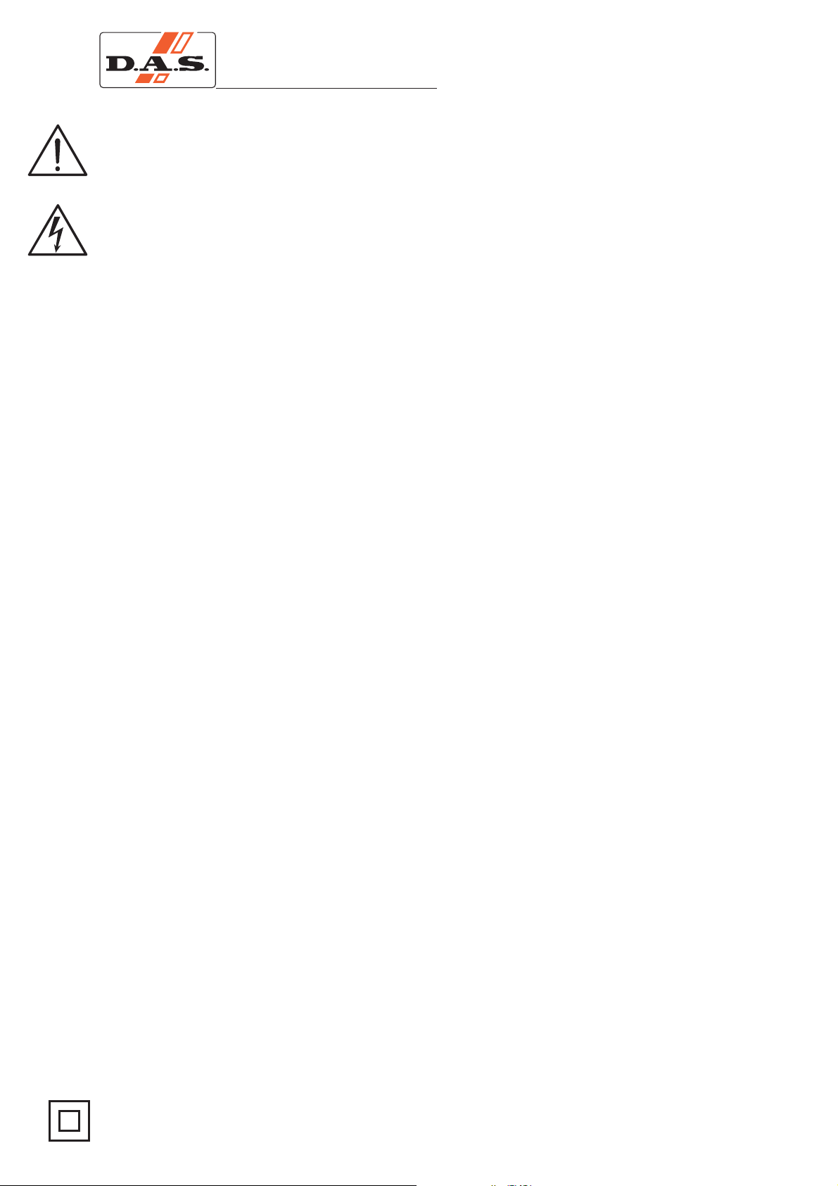
D.A.S. Audio AERO-38 and AERO-182 line
array systems, include 2 rigging structures on each
side of the box. Manufactured from zinc plated steel
they are painted black and are affixed to an internal
plate with special cropresistant screws. Two special
stainless steel guides are assembled to each of the
structures: G1A48 (front guide) and G2A48 (back
guide), allow for stacking or flying of boxes.
To lock both guides, six (6) quick release safety pins
(supplied)must beused.
The G1A48 front guide provides a solid
connection to the box and whatever is on top of it,
while the G2A48 rear guide determines the vertical
splay angle (whether stacked or flown), as a function
ofthe holewhere thepin getsinserted.
2.2 DESCRIPTION/ACCESSORIES
Splay
angles can be changed from 0º to 3.2º in 0.8º
increments and from 3.2º to 9.6º in 1.6º increments.
Aero-38 Manual del usuario/ User´s manual 44
G2A48
G1A48
QUICK RELEASE PIN 8X30
(6 UNITS PER CABINET)
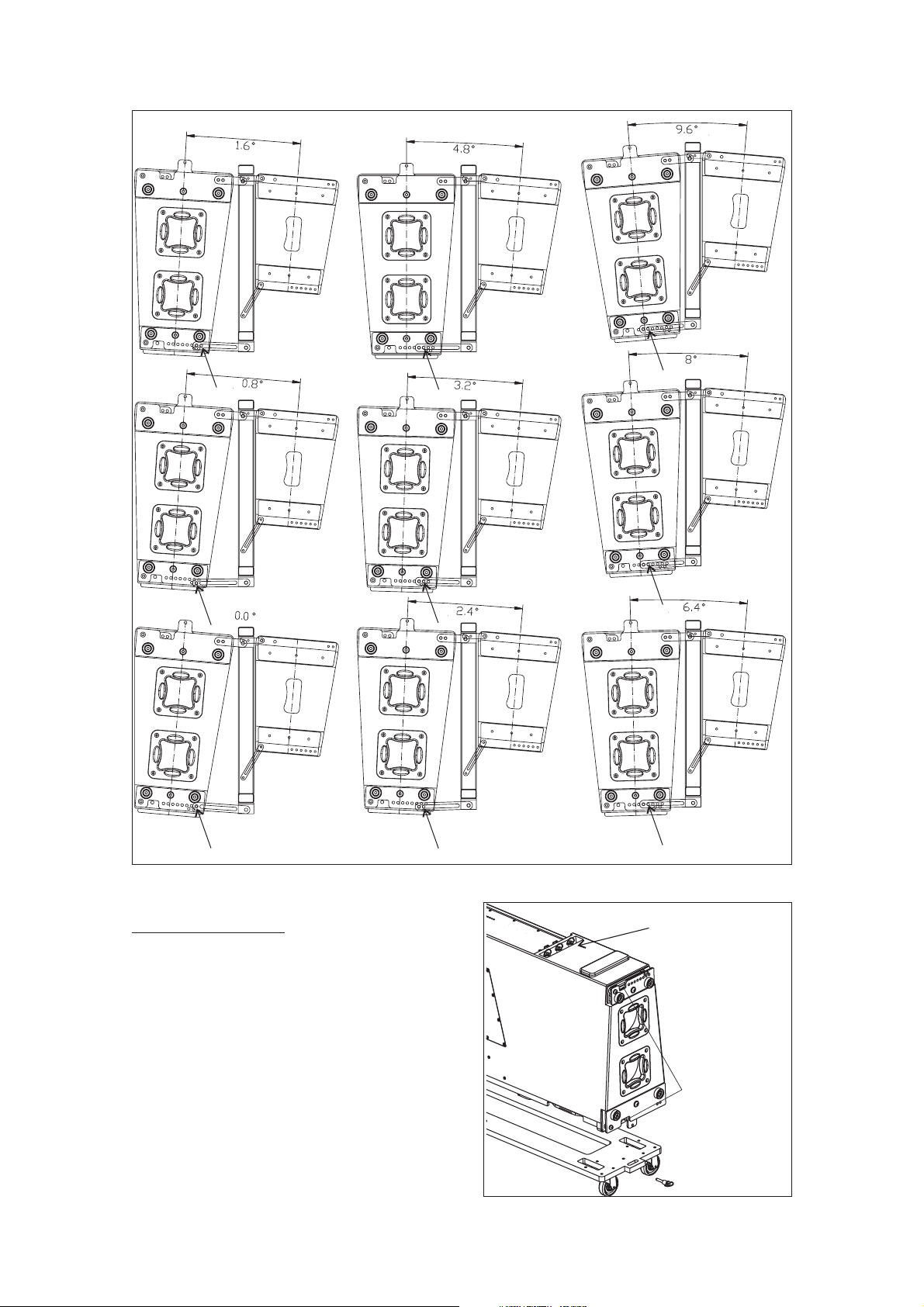
To aid the setting of the G2A48 guide in the
corresponding hole inthe topbox, each hole is labeled
with an associated angle, both for stacked and flown
applications. To fit the guides into the holes, highly
resistant 8 mm quick release pins with a ball safety
lock are used.
4.8º
6.4º
8º
9.6º
3.2º
1.6º
0º
0.8º
STACK
4.8º
6.4º
8º
9.6º
3.2º
1.6º
0º
0.8º
2.4º
FLY
Splay angles
STACK
FLY
For flying boxes and defining the splay
angle, thepins must beinserted in the of guide2,
G2A48, whereas for stacking ( ), the pin goes
throughthe ofthe guide.
slot
top hole
stacked
All of theelements needed to rig orstack the
systems areintegral to theenclosure (
and the quick release safety pins). The additional
items needed are the AX-AERO48 or AX-AERO38
flying grids (bumper bars),chains and hoists, the PL-
38 or PL-48S dolly platforms and the AX-COMBO
G1A48, G2A48
A) AX-AERO48 andAX-AERO38
The AX-AERO48 grid is made from 100 x 50
x 6mm steel beams and is designed to handle great
loads. It features a center reinforcement bar that is
also used for the lifting slings. The force of both the
rear and the front chain hoist will determine the tilt
angle of the whole array. The structure will be
attachedto thefirst enclosureof thearray bymeans of
the guides G1A48, G2A48, and six quick release
safetypins.
Weight
Dimensions: 144x93x10 cm
(HxWxD)
: 75Kg (165 lbs)
57x36.6x4 in
Pickup points
Aero-38 Manual del usuario/ User´s manual 45
The AX-AERO38grid is lighter than theother one, and
it is recommended to be used to fly a maximum of 8
cabinetsAERO-38Aor 6AERO-48.
Weight
Dimensions: 147x62x10 cm
(AlxAnxP)
: 60Kg (132 lbs)
57.8x24.4x4 in
For example, if 12 units AERO-48 are going
to be flown from the AX-AERO48, each hoist to be
usedshould havea loadcapacity of2 ton.
>750Kg
>750Kg
>750Kg
1 6units-->
1 6units-->
1 8units-->
AERO-48
AERO
182
AERO-38
AX-AERO38
AX-AERO48
>1000Kg
>1000Kg
>750Kg
>2000Kg
>2000Kg
>1500Kg
1 8units-->
1 8units-->
1 10units-->
9 16units-->
9 16units-->
11 20units-->
AERO-48
AERO
182
AERO-38
Load capacity per hoist (safety factor 10:1)
B) Chain hoists
All units in a column will be flown from the
AX-AERO48 (AX-AERO38) flying grid (bumper bar),
which should be used with two hoists, one located in
the front and the other in the rear. Each hoist should
have a minimum of1 Ton load capacity when flying up
8 units and a 2 Ton load capacity when flying 9 to 16
units.
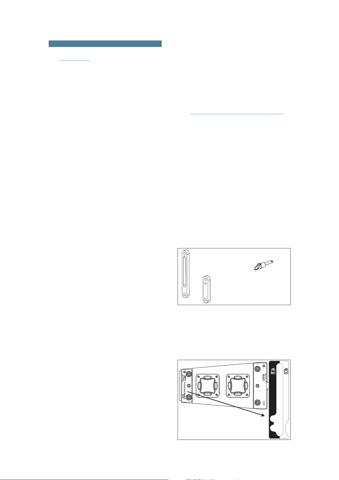
C) Platforms PL-48 and PL-38
The PL-38 dollypanels facilitate transport of
the AERO-38 systems. They can also be used to
facilitate flying the systems. Each coveris attachedto
the enclosure by using the flying hardware attached
to each box and is fixed with thequick release safety
pins. The AERO-182 systems also include one PL-48
dollypanel percabinet.
AERO-182
PL-48
AERO-38
PL-38
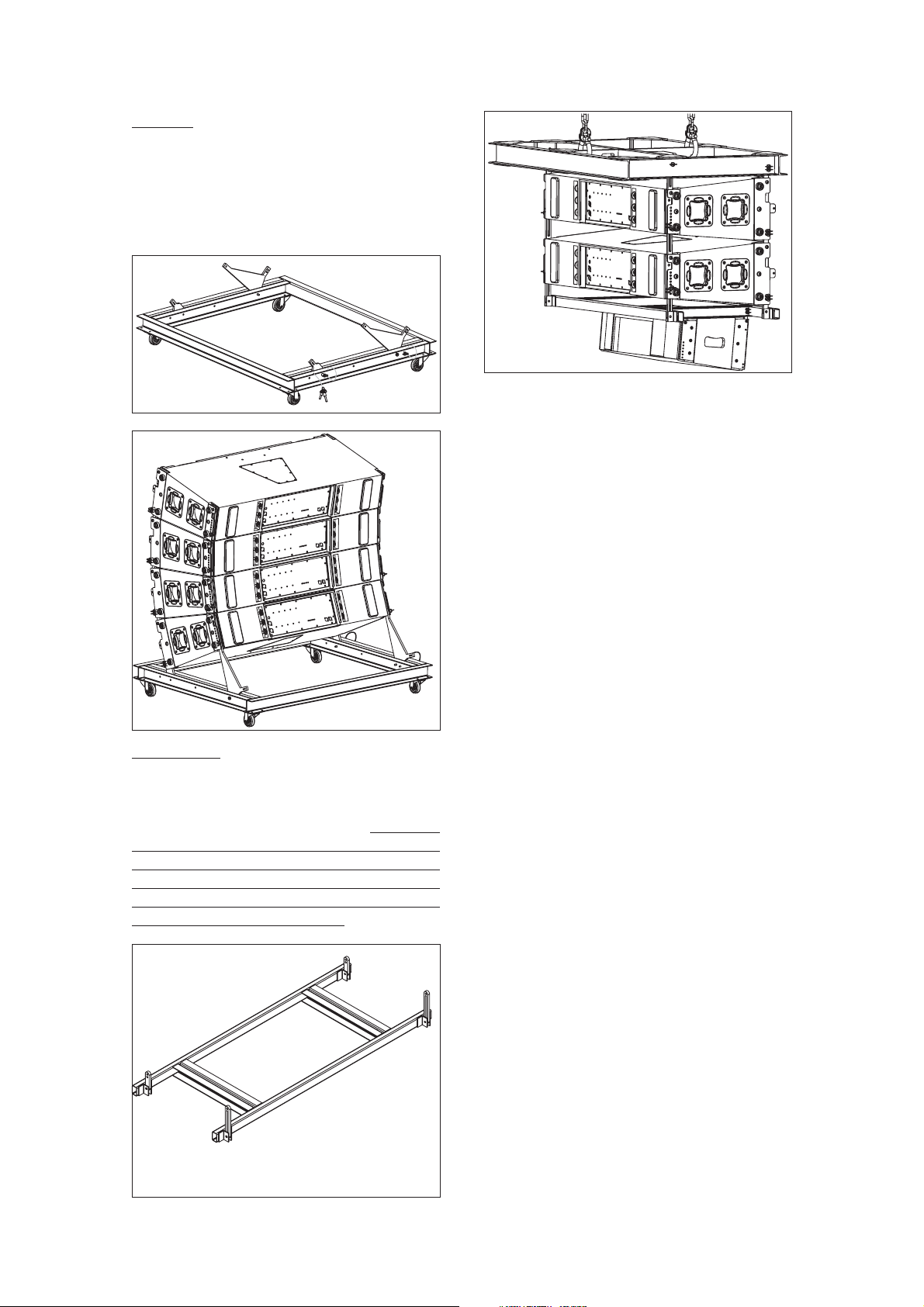
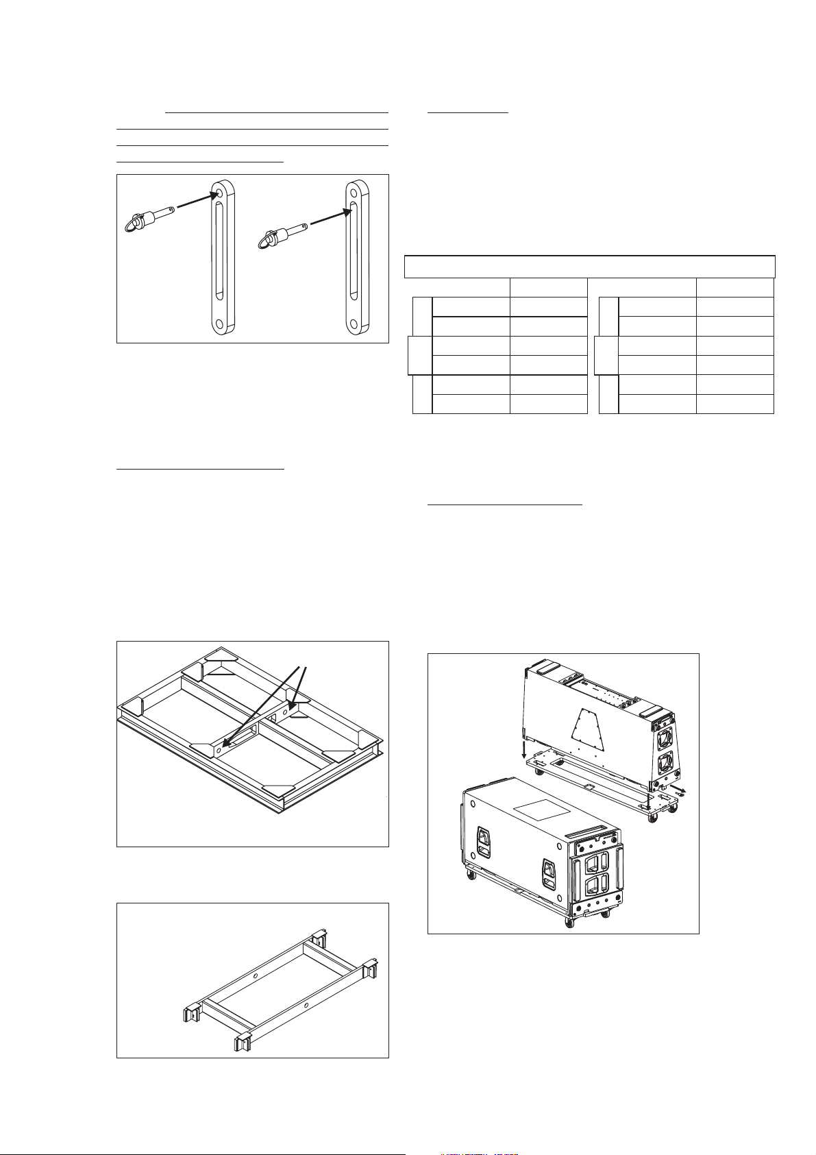
D) PL-48S
The PL-48Splatform isa valuableaccessory
which allowsup to 4 AERO-38units to betransported
in astacked position,ready tobe flown. The PL-48S is
made from steel and has 4 heavy duty casters with
lockingbrakes.
Aero-38 Manual del usuario/ User´s manual 46
PL-48S
AX-COMBO
AERO-38
AERO-28
AX-AERO48
E) AX-COMBO
The AX-COMBO is a rigging adapter to be
used when Aero-28 units are needed to be flown
under AERO-38 units as dowfillsystems. Maximum 6
CA-28A unitsand 8CA-28/CA-28B units can be flown
from this rigging grid. The AX-COMBO includes front
and rear steel guides which permit variation of the
angle between it and the last AERO-38 cabinet in the
cluster.Anglesvary from0.0º to9.6º.
AX-COMBO
G2A48
G1A48
G2A48
Weight
Dimensions: 143x60x5cm (56.3x23.6x2in)
: 16.5Kg (36.3 lbs)
G1A48
The AX-COMBO is joined to the last AERO-
38 cabinet using G1A48 and G2A48 included steel
guides and6 quickrelease pins.The angledepends on
the hole of the rigging structures where the pins are
inserted, through the slots of G2A48. The first AERO-
28 unit is joined to the AX-COMBO using its G1A and
G2Aincluded camlinks.
On the next page is a table with the angles between
both systems depending on the hole where the quick
releasepin isbeing inserted.
SPLAY ANGLES USING THE AX-COMBO
F) QUICK RELEASE PINS
Each cabinet includes 6 steel heavy duty
quick release pins stored on the rear panel of the
cabinets.
Both systemsAERO-38, andAERO-182 can
be flown using steel structures located on boths sides
of the cabinets. NEVER REPLACE QUICK RELEASE
PINSWITH SCREWSOR OTHERELEMENTS!!!
Pins can be used to
free the pieces
G1A48, G2A48.
Pins
Aero-38 Manual del usuario/ User´s manual 47
2.3 SAFETY FACTORS
breaking load limit and the
maximum safe working load limit (SWLL). In this
case, the breaking load limit of each of the flying
points is 4,000 kg (8,820 lbs) as determined by
destructive testing in independent laboratories. With
a 10:1safety factor, atotal amount of 1,600 kg(3,527
lbs) can be flown from the 4 flying points. Each flying
point has a capacity of 400 kg (882 lbs) with a 10:1
safetyfactor.
The safety factor is defined as the
coefficient between the
T
Theuse oftwo hoistswith aload capacityas
expressed on the previous page is mandatory. It
should be kept in mind that at certain moments, the
complete load may be supported by only one of the
hoists.
he maximum number of AERO-38 units
that can be suspended from the AX-AERO48 flying
grid is 20 (with 10:1 safety factor). T
The
maximum limits established by the manufacturer
shouldnever beexceeded.
This is why the load capacity of the individual
hoist must be superior to the weight of the array
column.
NOTE: The rigging systems of the AERO-38 and the
AERO-48 are compatible. Some accessories (AX-
AERO38,AX-AERO48) canbe usedby bothsystems.
he maximum
number of AERO-182 units that can be suspended
from the AX-AERO48 flying grid is 16 (10:1).
Aero-38 Manual del usuario/ User´s manual 48
4 x 400Kg (10:1)
3.1 AERO-38A
3. SELF-POWERED SYSTEMS
The Aero-38A is a three way, class D, self
powered system.
Nominal amplifier power (RMS) per way:
LF:1000W MF: 500W HF:500W
Amplifierpanel description:
A) : A
B) :
C) :
E) .
F1) :
F2) :
6 (at 230V)
G) :
1=GND(ground)
2=(+)Non invertedinput
3=(-)Inverted input
H) :
LIMIT
SIGNAL
ON
FUSE
AC INPUT
AC OUTPUT
INPUT
LOOP THRU
D) : Indicatesthat theamplifier
is underprotection mode because damage riskdue to
shortcircuit orextreme workingtemperature.
PROTECTION
mplifier limiter indicator lights.
When lit, the level of the signal source should be
reduced.
Signal presence indicator at the
amplifiers'inputs.
Indicator light for each amplifier
channel.
With PowerCon NAC 3 FCA
connector. Only when the connector is inserted and
rotated (clicked) into place will the AC turn on. The
connector can be used as a switch, rotating the
connector to or from the locked position will turn the
unit onor off,respectively.Mute thesignal feedingthe
beforeturning theunit onor off.
With (white) PowerCon
NAC 3 DFCB connector. This is used as an AC loop
thru sothat upto boxes can bepower from
asingle ACline.
Balanced signal XLR. Pin
assignmentsas follows:
Used for paralleling several
units, which will share the same input. The outputcan
also be used to provide signal for an outboard power
amplifier.
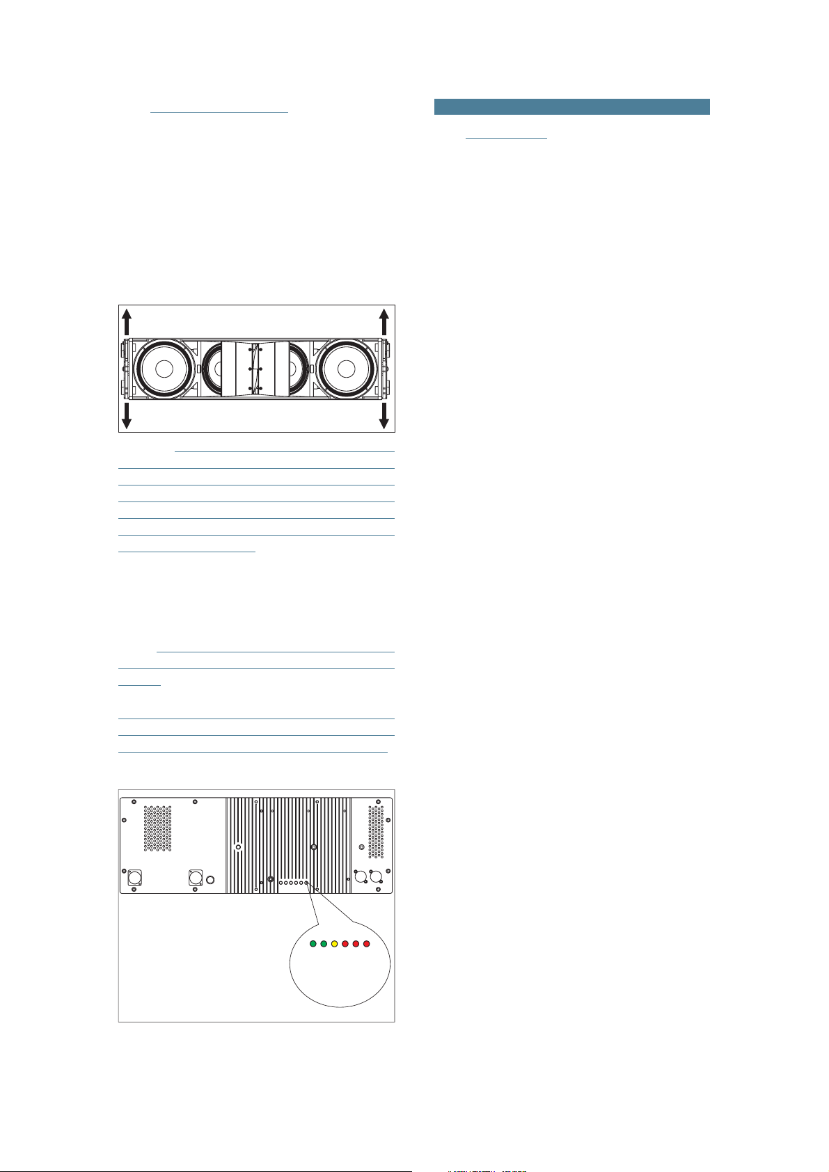
INPUT
Rear panel of the AERO-38A amplifier.
F2-PowerCon NAC 3DFCB
HF
G-Input XLR
E-Fuse
H-Output XLR
F1-PowerCon NAC 3FCA
SIGNAL
MF
LF
ON
PROTECTION
DAAAB
ZOOM
H
G
F1
E
F2
C

Low frequency mono-amplified system.
Nominal amplifier power (RMS) 1000W.
Amplifierpanel description:
mplifier limiter indicator lights.
When lit, the level of the signal source should be
reduced.
Signal presence indicator at the
amplifiers'inputs.
Indicator light for each amplifier
channel.
With PowerCon NAC 3 FCA
connector. Only when the connector is inserted and
rotated (clicked) into place will the AC turn on. The
connector can be used as a switch, rotating the
connector to or from the locked position will turn the
unit onor off,respectively.Mute thesignal feedingthe
beforeturning theunit onor off.
Balanced signal XLR. Pin
assignmentsas follows:
Used for paralleling several
units, which will share the same input. Could also be
usedto providesignal foran outboardpower amplifier.
H) : Used to control the
subwoofer level. To prevent accidental mis-setting, a
flat-blade screwdriver isneeded to rotate the control,
which is recessed and detented. Depending on the
sensitivity, placement and configuration of your mid-
high system, you may need to adjust this control for
balancedfrequency response.
INPUT
SUB LEVEL
NOTE: The amplifiers on the AERO-218A
and AERO-182A systems do not inlclude a filtered
satelliteoutput forAERO-38A systems.
A) : A
B) :
C) :
D) .
):
F) :
1=GND(ground)
2=(+)Non invertedinput
3=(-)Inverted input
G) :
LIMIT
SIGNAL
ON
FUSE
E AC INPUT
INPUT
LOOP THRU
3.2 AERO-182A
The required voltage for all models is:
115V, 50Hz/60Hz - 230V, 50Hz/60Hz
Maximum voltage (divide by 2 for115V):
264V
Shutdown voltage (divide by 2 for 115V):
Aero-38A: 156V
Aero-182A / Aero-218A: 160V
3.5 CURRENT CONSUMPTION
F
D
H
G
A
C
B
E
Amplifier panel on AERO-218A and AERO-182A
systems.
3.3 AERO-218A
The Aero-218A is a low frequency mono-
amplified system.
Nominal amplifier power (RMS) 2 x 1000W.
3.4 AC POWER REQUIREMENTS
AERO-182A / AERO-218A *
Maximum Power
AERO-38A
Maximum Power 8A
Sine 85Hz
2.5A
Pink noise
1/3 Power
3.2A
1/8 Power
1.6A
Idle
0.25A 0.25A
Data obtained at 230V, multiply per 2 for 115V.
*For 2000W versions multiply per 2.
Maximum power: Measured in conditions of severe
clipping.
1/3 Power
1/8 Power
Idle
Aero-38 Manual del usuario/ User´s manual 49
7A 2.5A
Sine 50Hz Pink noise
3.0A
----
----
1.1A
0.1A 0.1A
----
----

A sound system should be switched on
sequentially. Switch on the self-powered unit last in
your sound system. Switch on the sound sources
such asCD players or turntables, thenthe mixer, then
the processors, and finally the self-powered unit. If
you have several units, it is recommended that you
switchthem onsequentially oneat atime.
Follow theinverse orderwhen switchingoff,
turning self-powered units off before any other
elementin thesound system.
Mute all signal sourcesbefore switching the
uniton oroff.
It is recommended that the red LED
indicators are not lit continuously; at most it should
blinkonly occasionally.
If you wish to have a visual indicationat the
mix position of whether the LIMIT LEDs are lighting,
during equipment set-up, closelyobserve what mixer
VUmeter level corresponds to the level that lights the
enclosure's LIMIT LEDs. That level that should not be
exceededduring theevent.
LIMIT
Due to their high efficiency, the Aero Series
amplifiers generate very little residual heat and
therefore do not need a fan for cooling. In normaluse,
theamplifier panelwill bewarm tothe touch.
If theunit stops playing(or just the mid-high
or the bass sections), the amplifier's overheating
protection may be activated to protect the
componentsfrom thermaldamage.
Overheating may be due to insufficient
cooling, or to very aggressive use in extremely hot
conditions. Do not use the unit in proximity to high
powerlights.
Once the amplifier cools down, it switches
back on automatically. If the unit should shut down
again, try reducing the volume a notch to avoid
overheating.
3.7 INDICATORSOVERLOAD (LIMIT)
3.6 SWITCH ON-OFF
3.8 OVERHEATING
3.10 LOW MAINS VOLTAGE
If mains voltage falls below the shutdown
voltage for the unit, it will stop playing. When
acceptable levels are regained, the unit will switch
backon automatically.
3.9 ECUALIZATION
The AERO-38A can be used full-range. Full-
range use is only recommended for applications
where low SPL level and no bass reinforcement is
adequate. Touse it inthis mode simply plug themixer
intothe enclosure'sinput.
The most common use will be combined
with the AERO-218A (AERO-182A). In this case
different outputs of the mixing console will be used
with theAERO-38A andthe SUBS. Both sub systems,
AERO-182A andAERO-218A include signal treatment
in the amplifiers extending their frequencyrange up to
85Hz. As well, the amplifier of the AERO-38A
incorporates signal treatment which provides
frequency range extension down to 60Hz. Due to this
overlap between 60-85Hz the use of an
to control and adjust the phase of the subs
external
delay is
recommended.
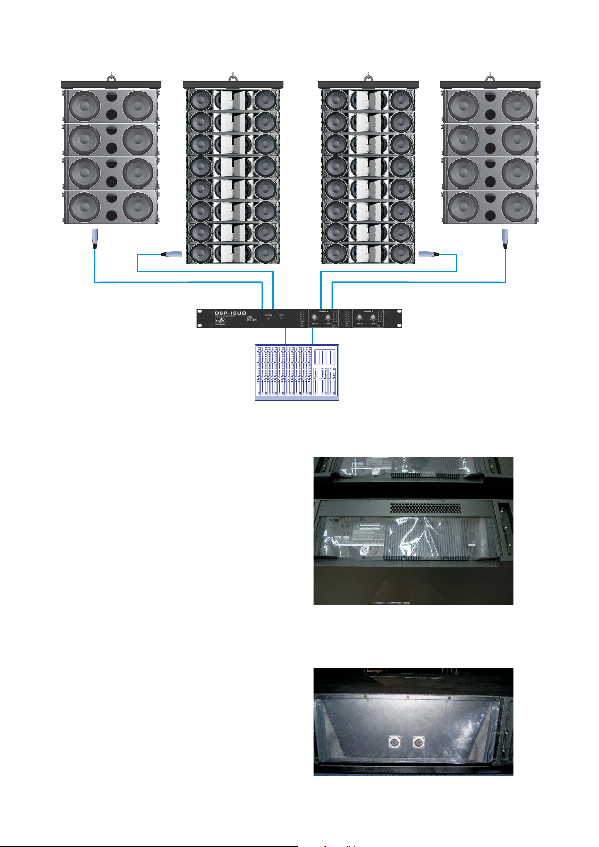
3.11 CONNECTIONS
AERO-38A
Mezclador/Mixer
Retardo/
Delay
AERO-182A
Procesador/
processor
The connector is an output XLR
in parallel with the input connector and is useful for
daisy chaining the input signal to a number of boxes,
connectingthem inparallel.
The number of units that can be linked this
way depends on the output impedance of the
equipment drivingthe enclosure, such as the mixeror
processor. Typically, to avoid signal degradation, the
maximum number that can be daisy chained is given
by the formula Zc>10Zs, where Zc is the load
impedance and Zs is the output impedance of the
equipment driving theenclosure (mixer, console, etc).
For instance, a mixing console with 100 ohm output
impedance allowsdaisy chaining 20boxes, when the
inputimpedance ofthe cabinetsis 20Kohm.
LOOP THRU
Aero-38 Manual del usuario/ User´s manual 50
The units do not need extreme EQ. Avoid
high levels of gain on the equalizers. Gain values
above +6 dB on a console's EQ are not
recommended.
Aero-38 Manual del usuario/ User´s manual 51
As can be seen in the diagram, independent signal lines exist forthe subwoofer units, AERO-182A. The signal that
goesto thesubs isprocessed bymeans ofthe DSP-1Subto adjustthe delaybetween bothsystems.
3.12 RAIN PROTECTOR
Electronic devices can be damaged when
exposed to water or moisture. AERO-38A and AERO-
182A/218A amplifiers must be protected when
installed outdoors. A rain protector is supplied with
eachAERO-38Aand AERO-182A/218Aunit.
The rain protector is specially designed to
withstand soft rain and other meteorological
conditions for short periods of time. In the case of
heavy rains, storms or permanent outdoors
installations the sound system must be protected
withadditional elements.
The rain protectors supplied with each unit
havebeen manufacturedwith fireproofmaterials.
The AERO-38A's rain protector features
severalsmall holeson thetopside toallow convection
coolingof theamplifier.
AERO-38 rain protector.
NOTE: Therain protector of the AERO-38A is different
fromthe onethat includesthe AERO-38.
AERO-38A rain protector.
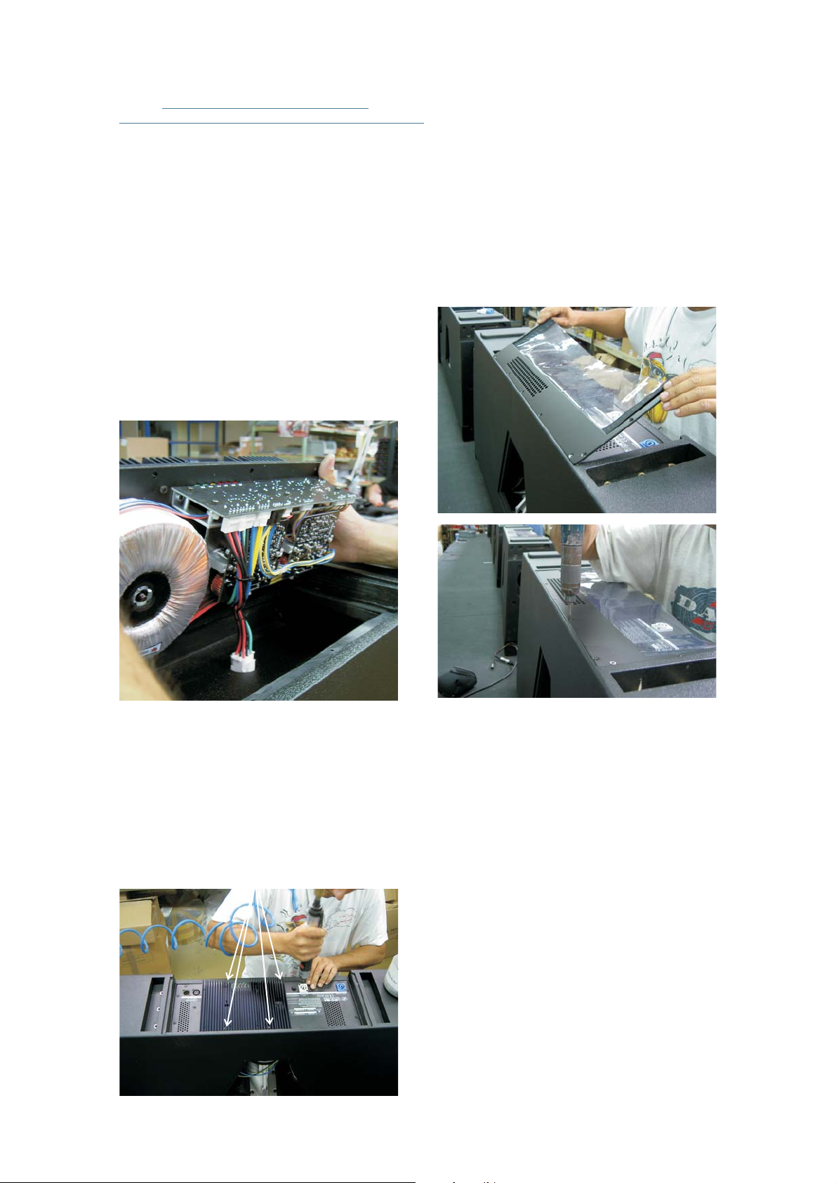
3.13
HOW TO MAKE A PASSIVE
SYSTEM INTO A SELF POWERED ONE.
This way the amplifier of the AERO-38A
systemhas beencorrectly installedin thebox.
convert
loosen
r.
remove 14 x
AERO-38 -->AERO-38A:
AERO-38 passive systems come with a
metallic backplate, protected bya rain protector,that
features two Speakon NL8 connectors. To a
passive system into an active one, firstly the
screws 11x (3.9x19Pv00)and therain protecto Once
this has been done, the M4x20 screws
thatfix theback plateto thebox.
On the rear side of theback plate the cables
coming from the Speakon connectors lead to a white
male connector, which is inserted in a white female
connector attached to the box. Unplug the male
connector coming from the Speakon connectors and
insertthe maleconnector oftheamplifier inthe female
connectoron thebox.
The fourM4x30 DIN 7985must be screwed
in thefour holes that canbe seen on theradiator area.
The white arrows in the picture above point to the
mentionedholes.
Different rain protectors are needed for the
passiveand theactive versions!!!
The rain protector for the self powered
version is supplied with the amplifier. In order to
attach it to the box just rest the protector on the
receptacleand retightenthe eleven3.9x19PV00 on.
The white connector mentioned above can
be plugged only in one way, so a mistake in the
connections is mechanically impossible. Make sure
that the connection is tight enough, then put the
amplifier in its receptacle paying attention that wires
donot getcaught.
The next step will be to fix the amplifier to
thebox withthe screwssupplied:
10x(M4x20 DIN 965)
4x(M4x30 DIN 7985)
Aero-38 Manual del usuario/ User´s manual 52
Aero-38 Manual del usuario/ User´s manual 53
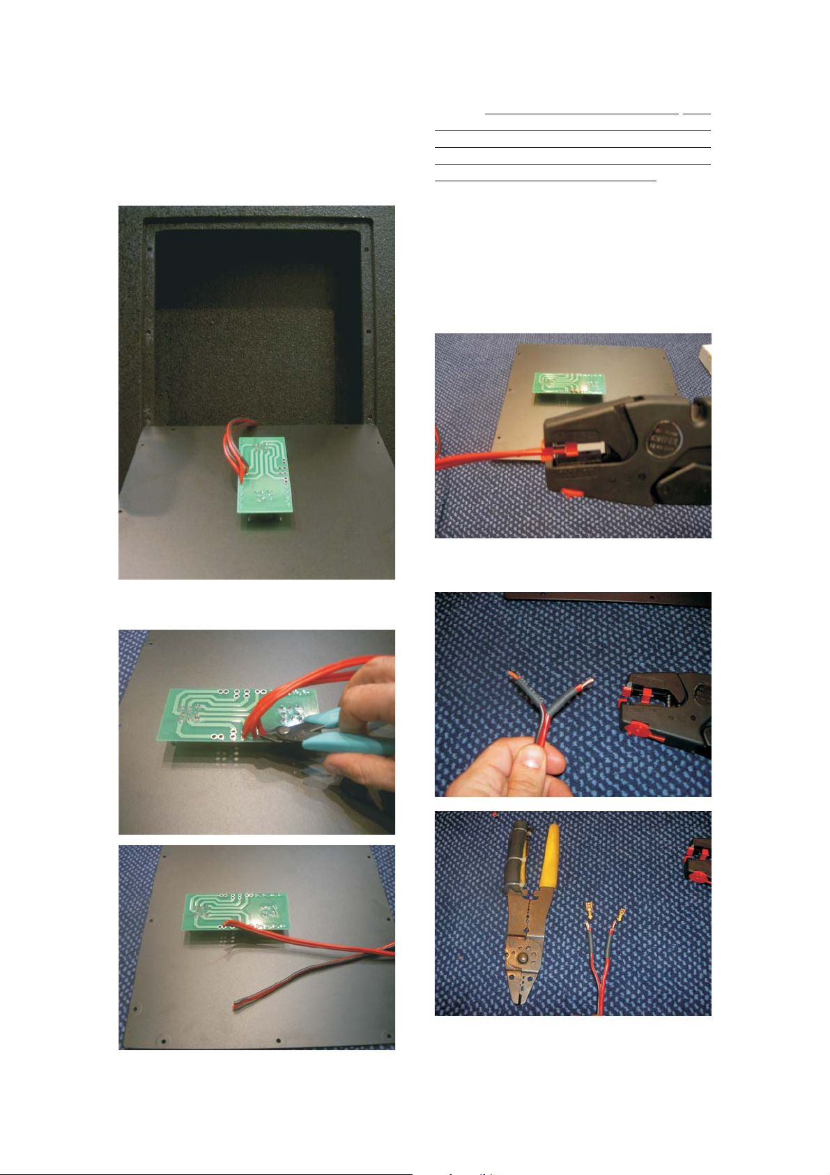
AERO-218Sub -->AERO-218A
To make a passive system into an active
one, firstly the back plate must be removed by
unscrewingthe 12M4x20 DIN965.
After cutting the speakers' wires on the
circuit board, terminals must beattached tothe
speakers' wires as follows: to assure current polarity
attach large 6.3mm female terminal to the
black wire, and a smaller 4.8mm female
terminal to the red wire. Connecting the terminals to
the correct male terminals on the amplifier circuit
boardamplifie, thepolarity willbe correct.
faston
faston ,
faston
It is highly advisable to shield the terminals
withtape orthermoretractable material:
Thenthe speakerwires mustbe cutfrom the
circuitboard.
NOTE: As AERO-218A and AERO 182A
amplifiers' polarity is inverted referenced to that of
conventional external amplifiers, the polarity of the
speakers' wires must be changed when switching
froma passiveto anactive AeroSeries sub.
-

Aero-38 Manual del usuario/ User´s manual 54Aero-38 Manual del usuario/ User´s manual
The large terminal
should be attached to the black wire, and the small
terminal should be attached to the
redwire:
faston
faston
6.3mm wide
4.8mm wide
In the case of the AERO-218A the same
processapplies tothe secondamplifier inthe box.
Should you have any problem during this
process do not hesitate to contact D A S factory or
ourregional dealer.
...
 Loading...