

Page 1
MAKING MODERN LIVING POSSIBLE
Installation Guide
Danfoss Turbocor
www.danfoss.com/drives
Page 2

Page 3

Contents Installation Guide
Contents
1 Introduction
1.1 Product Overview
1.2 Purpose of the Manual
1.3 Product Overview
1.4 Internal Controller Functions
2 Safety
2.1 Safety Symbols
3 Installation
3.1 Planning the Installation Site
3.2 Pre-Installation Check List
3.3 Mechanical Installation
3.3.1 Cooling 6
3.3.1.1 Refrigerant Cooling 6
3.3.2 Lifting 7
3.3.3 Wall Mounting - IP21 (NEMA 1) Units 7
3.4 Electrical Installation
3
3
4
4
4
5
5
6
6
6
6
7
3.4.1 General Requirements 7
3.4.2 Grounding Requirements 10
3.4.2.1 Leakage Current (>3.5 mA) 10
3.4.2.2 Grounding IP21 Enclosures 11
3.4.3 Motor Connection 11
3.4.3.1 Terminal Locations 12
3.4.4 Motor Cable 13
3.4.5 Motor Rotation Check 13
3.4.6 AC Mains Connection 13
3.4.7 DC-Link Connection 13
3.5 Control Wiring Connection
3.5.1 Access 14
3.5.2 Using Screened Control Cables 14
3.5.3 Grounding of Screened Control Cables 14
3.5.4 Control Terminal Types 15
3.5.5 Wiring to Control Terminals 16
3.6 Serial Communication
14
16
4 Start Up and Commissioning
4.1 Pre-start
4.2 Applying Power
MG35Q202 Danfoss A/S © 01/2015 All rights reserved. 1
17
17
18
Page 4

Contents Danfoss Turbocor
5 Specifications
5.1 Power-dependent Specifications
5.2 General Technical Data
5.3 Fuse Tables
5.3.1 Protection 22
5.3.2 Fuse Selection 22
5.3.3 Short Circuit Current Rating (SCCR) 23
5.3.4 Connection Tightening Torques 23
Index
19
19
20
22
24
2 Danfoss A/S © 01/2015 All rights reserved. MG35Q202
Page 5
1
15
14
8
9
12
13 (IP 20/Chassis)
13
(IP 21/54
NEMA 1/12)
11
10
16
130BC252.11
130BC301.11
1
2
3
4
5
6
7
8
9
10
11
Introduction
1 Introduction
1.1 Product Overview
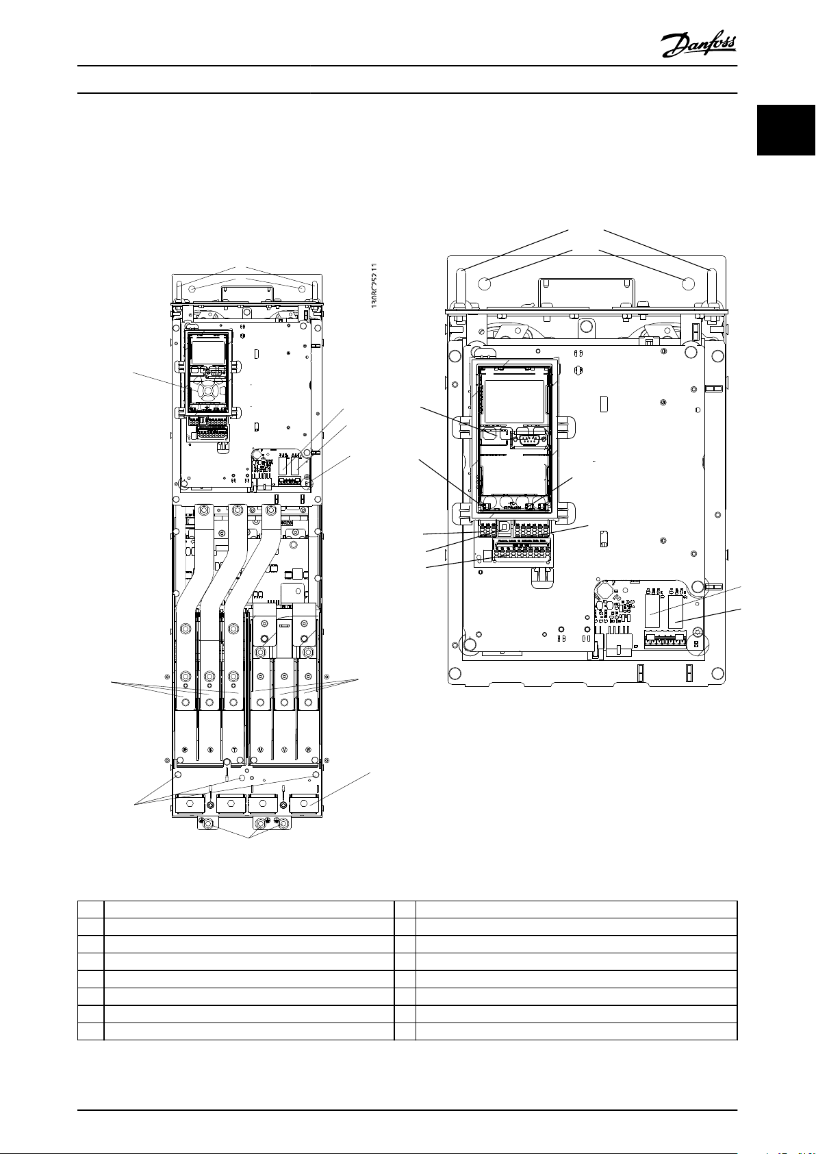
1.1.1 Interior Views
Installation Guide
1
1
Illustration 1.1 D1 Interior Components
LCP (Local Control Panel) 9 Relay 2 (04, 05, 06)
1
2 RS-485 serial bus connector 10 Lifting ring
3 Digital I/O and 24 V power supply 11 Mounting slot
4 Analog I/O connector 12 Cable clamp (PE)
5 USB connector 13 Earth (ground)
6 Serial bus terminal switch 14 Motor output terminals 96 (U), 97 (V), 98 (W)
7 Analog switches (A53), (A54) 15 Mains input terminals 91 (L1), 92 (L2), 93 (L3)
8 Relay 1 (01, 02, 03) 16 TB5 (IP21 only). Terminal block for anti-condensation heater
Table 1.1 Legend to Illustration 1.1 and Illustration 1.2
Illustration 1.2 Close-up View: LCP and Control Functions
MG35Q202 Danfoss A/S © 01/2015 All rights reserved. 3
Page 6
Introduction Danfoss Turbocor
1
1.2 Purpose of the Manual
This manual provides detailed information for the installation and start up of the frequency converter.
Chapter 3 Installation provides requirements for mechanical
and electrical installation, including:
Input
•
Motor
•
Control wiring
•
Serial communications wiring
•
Control terminal functions
•
VLT® is a registered trademark.
1.3 Product Overview
A frequency converter is an electronic motor controller
that converts DC into a variable AC waveform output. The
frequency and voltage of the output are regulated to
control the motor speed or torque. The frequency
converter can vary the speed of the motor in response to
remote commands from external controllers.
The frequency converter offers many control, monitoring
and efficiency functions such as
monitoring the system and motor status
•
Issuing warnings or alarms for fault conditions
•
starting and stopping the motor
•
optimising energy efficiency
•
Operation and monitoring functions are available as status
indications to an outside control system or serial communication network.
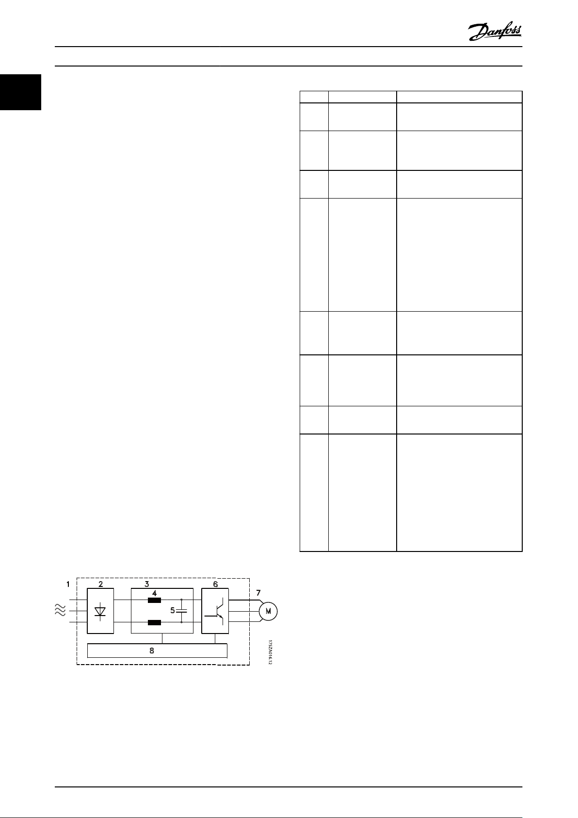
1.4
Internal Controller Functions
Illustration 1.3 is a block diagram of the frequency
converter's internal components.
Area Title Functions
3-phase AC mains supply to the
1 Mains input
2 Rectifier
3 DC-bus
4 DC reactors
5 Capacitor bank
6 Inverter
7 Output to motor
8 Control circuitry
Table 1.2 Legend to Illustration 1.3
•
frequency converter
The rectifier bridge converts the
•
AC input to DC current to
supply inverter power.
Intermediate DC-bus circuit
•
handles the DC current.
Filter the intermediate DC circuit
•
voltage.
Prove line transient protection.
•
Reduce RMS current.
•
Raise the power factor reflected
•
back to the line.
Reduce harmonics on the AC
•
input.
Stores the DC power.
•
Provides ride-through protection
•
for short power losses.
Converts the DC into a
•
controlled PWM AC waveform
for a controlled variable output
to the motor.
Regulated 3-phase output
•
power to the motor
Input power, internal processing,
•
output, and motor current are
monitored to provide efficient
operation and control.
User interface and external
•
commands are monitored and
performed.
Status output and control can
•
be provided.
Illustration 1.3 Frequency Converter Block Diagram
4 Danfoss A/S © 01/2015 All rights reserved. MG35Q202
Page 7
Safety
Installation Guide
2 Safety
2.1 Safety Symbols
WARNING
HIGH VOLTAGE
Frequency converters contain high voltage when
connected to AC mains input power. Qualified personnel
only should perform installation, start up, and
maintenance. Failure to perform installation, start up,
and maintenance by qualified personnel could result in
death or serious injury.
WARNING
UNINTENDED START
When the frequency converter is connected to AC mains,
the motor may start at any time. The frequency
converter, motor, and any driven equipment must be in
operational readiness. Failure to be in operational
readiness when the frequency converter is connected to
AC mains could result in death, serious injury,
equipment, or property damage.
2 2
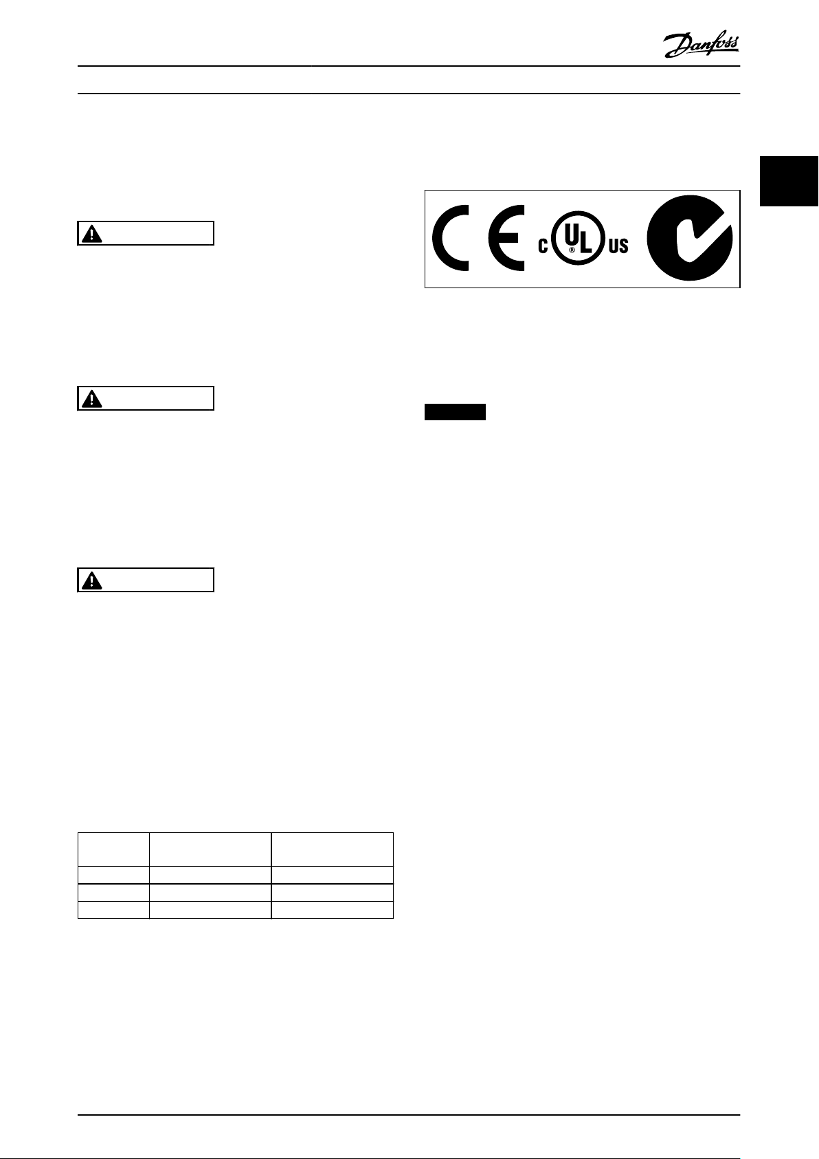
Table 2.2 Approvals
The frequency converter complies with UL508C thermal
memory retention requirements. For more information,
refer to the section Motor Thermal Protection in the
product specific design guide.
NOTICE
Imposed limitations on the output frequency
(due to export control regulations):
From software version 6.72 onwards, the output
frequency of the frequency converter is limited to 590
Hz. Software versions 6x.xx also limit the maximum
output frequency to 590 Hz, but these versions cannot
be flashed, that is, neither downgraded nor upgraded.
WARNING
DISCHARGE TIME
Frequency converters contain DC-link capacitors that can
remain charged even when the frequency converter is
not powered. To avoid electrical hazards, disconnect AC
mains, any permanent magnet type motors, and any
remote DC-link power supplies, including battery backups, UPS, and DC-link connections to other frequency
converters. Wait for the capacitors to fully discharge
before performing any service or repair work. The
amount of wait time is listed in the Discharge Time table.
Failure to wait the specified time after power has been
removed before doing service or repair could result in
death or serious injury.
Voltage [V] Power range [kW] Minimum waiting time
(minutes)
3x400 110-315 20
3x460 110-315 20
3x575 110-315 20
Table 2.1 Discharge Time
MG35Q202 Danfoss A/S © 01/2015 All rights reserved. 5
Page 8
Installation
Danfoss Turbocor
3 Installation
3.1 Planning the Installation Site
Ensure that frequency converter output current
33
NOTICE
Before performing the installation it is important to plan
the installation of the frequency converter. Neglecting
this may result in extra work during and after installation.
Select the best possible operation site by considering
the following (see details on the following pages and
the respective Design Guides):
Ambient operating temperature
•
Installation method
•
How to cool the unit
•
Position of the frequency converter
•
Cable routing
•
Ensure the power source supplies the correct
•
voltage and necessary current
Ensure that the motor current rating is within the
•
maximum current from the frequency converter
If the frequency converter is without built-in
•
fuses, ensure that the external fuses are rated
correctly
Voltage [V] Altitude restrictions
380-500 At altitudes above 3,000 m, contact Danfoss
regarding PELV
525-690 At altitudes above 2,000 m, contact Danfoss
regarding PELV
Table 3.1 Installation in High Altitudes
3.2
Pre-Installation Check List
Before unpacking the frequency converter, ensure
•
the packaging is intact. If any damage has
occurred, immediately contact the shipping
company to claim the damage.
Before unpacking the frequency converter, locate
•
it as close as possible to the final installation site
Compare the model number on the nameplate to
•
what was ordered to verify the proper equipment
Ensure each of the following are rated for the
•
same voltage:
Mains (power)
•
Frequency converter
•
Motor
•
•
rating is equal to or greater than motor full load
current for peak motor performance
Motor size and frequency converter
•
power must match for proper overload
protection
3.3 Mechanical Installation
3.3.1 Cooling
Top and bottom clearance for air cooling must be
•
provided. Generally, 225 mm (9 in) is required.
Improper mounting can result in over heating
•
and reduced performance
NOTICE
A door fan(s) is required on the enclosure to remove the
heat not contained in the backchannel of the frequency
converters and any additional losses generated by other
components inside the enclosure. The total required air
flow must be calculated so that the appropriate fans can
be selected.
Airflow
The necessary airflow over the heat sink must be secured.
The flow rate is shown in Table 3.2.
Frame Door fan/top fan Heat sink fan
D1h
D2h
Table 3.2 Airflow
3.3.1.1
The Danfoss Turbocor frequency converters are equipped
with refrigerant cooling.
The refrigerant inlet is on the top of the frequency
converter to the left.
The refrigerant outlet is on the top of the frequency
converters to the right.
Dimensions
Material COPPER ALLOY 122, ASTM B-75, annealed
Nominal operating
pressure
Maximum working
pressure
Table 3.3 Tubing Specifications
102 m3/hr (60 CFM) 420 m3/hr (250 CFM)
204 m3/hr (120 CFM) 840 m3/hr (500 CFM)
Refrigerant Cooling
3/8 inch OD X 0.049 inch wall thk
10 bar/145 psi
12 bar/174 psi
6 Danfoss A/S © 01/2015 All rights reserved. MG35Q202
Page 9
Installation
Installation Guide
WARNING
CONDENSATION
Condensation must not be allowed to form on the inside
of the frequency converter. The flow of refrigerant must
be controlled in a way that ensures that the temperature
of the internal heatsink stays above the dew point.
Failure to control condensation will result in damage to
the frequency converter.
3.3.2 Lifting
WARNING
RISK OF INJURY OR DEATH
The lifting bar must be able to handle the weight of the
frequency converter to ensure that it will not break
during lifting.
See chapter 5.1 Power-dependent Specifications
•
for the weight of the different enclosure types.
Maximum diameter for bar is 2.5 cm (1 inch).
•
The angle from the top of the frequency
•
converter to the lifting cable should be 60° or
greater.
Failure to follow recommendations could result in death
or serious injury.
WARNING
EQUIPMENT HAZARD!
Rotating shafts and electrical equipment can be
hazardous. All electrical work must conform to national
and local electrical codes. It is strongly recommended
that installation, start up, and maintenance be
performed only by trained and qualified personnel.
Failure to follow these guidelines could result in death or
serious injury.
CAUTION
WIRING ISOLATION!
Run input power, motor wiring and control wiring in
three separate metallic conduits or use separated
shielded cable for high frequency noise isolation. Failure
to isolate power, motor and control wiring could result
in less than optimum frequency converter and associated
equipment performance.
3 3
Wall Mounting - IP21 (NEMA 1) Units
3.3.3
Consider the following before selecting the final installation site:
Free space for cooling
•
Access to open the door
•
Cable entry from the bottom
•
3.4
Electrical Installation
3.4.1 General Requirements
This section contains detailed instructions for wiring the
frequency converter. The following tasks are described:
Wiring the motor to the frequency converter
•
output terminals
Wiring the AC mains to the frequency converter
•
input terminals
Connecting control and serial communication
•
wiring
After power has been applied, checking input
•
and motor power
MG35Q202 Danfoss A/S © 01/2015 All rights reserved. 7
Page 10

230 VAC
50/60 Hz
230 VAC
50/60 Hz
TB6 Contactor
TB5
R1
1
2
Brake Temp
(NC)
Anti-condensation heater (optional)
(optional)
91 (L1)
92 (L2)
93 (L3)
PE
88 (-)
89 (+)
50 (+10 V OUT)
53 (A IN)
54 (A IN)
55 (COM A IN)
0/4-20 mA
12 (+24 V OUT)
13 (+24 V OUT)
18 (D IN)
20 (COM D IN)
15 mA
200 mA
(U) 96
(V) 97
(W) 98
(PE) 99
(COM A OUT) 39
(A OUT) 42
0/4-20 mA
03
+10 VDC
0 VDC - 10 VDC
0/4-20 mA
24 VDC
02
01
05
04
06
240 VAC, 2A
24 V (NPN)
0 V (PNP)
0 V (PNP)
24 V (NPN)
19 (D IN)
24 V (NPN)
0 V (PNP)
27
24 V
0 V
(D IN/OUT)
0 V (PNP)
24 V (NPN)
(D IN/OUT)
0 V
24 V
29
24 V (NPN)
0 V (PNP)
0 V (PNP)
24 V (NPN)
33 (D IN)
32 (D IN)
1 2
ON
A53 U-I (S201)
ON
21
A54 U-I (S202)
ON=0-20 mA
OFF=0-10 V
95
400 VAC, 2A
P 5-00
(R+) 82
(R-) 81
+ - + -
(P RS-485) 68
(N RS-485) 69
(COM RS-485) 61
0 V
5 V
S801
RS-485
RS-485
21
ON
S801/Bus Term.
OFF-ON
3 Phase
power
input
Load Share
Switch Mode
Power Supply
Motor
Analog Output
Interface
Relay1
Relay2
ON=Terminated
OFF=Open
Brake
resistor
(NPN) = Sink
(PNP) = Source
= ==
240 VAC, 2A
400 VAC, 2A
0 VDC - 10 VDC
10 VDC
37 (D IN) - option
130BC548.12
Installation Danfoss Turbocor
33
8 Danfoss A/S © 01/2015 All rights reserved. MG35Q202
Illustration 3.1 Interconnect Diagram
Page 11

Motor
Line Power
Stop
Start
Speed
Control
130BX370.10
Installation Installation Guide
For safety, comply with the following requirements
Electronic controls equipment is connected to
•
hazardous mains voltage. Extreme care should be
taken to protect against electrical hazards when
applying power to the unit.
Run motor cables from multiple frequency
•
converters separately. Induced voltage from
output motor cables run together can charge
equipment capacitors even with the equipment
turned off and locked out.
Field wiring terminals are not intended to receive
•
a conductor one size larger.
Overload and equipment protection
An electronically activated function within the
•
frequency converter provides overload protection
for the motor. The overload calculates the level of
increase to activate timing for the trip (controller
output stop) function. The higher the current
draw, the quicker the trip response. The overload
provides Class 20 motor protection.
Because the motor wiring carries high frequency
•
current, it is important that wiring for mains,
motor power, and control are run separately. Use
metallic conduit or separated shielded wire. See
Illustration 3.2. Failure to isolate power, motor,
and control wiring could result in less than
optimum equipment performance.
3 3
Illustration 3.2 Example of Proper Electrical Installation Using
Conduit
MG35Q202 Danfoss A/S © 01/2015 All rights reserved. 9
Page 12

L1
L1L2L2L3L3
2
91 92 93
1
130BB460.11
Installation Danfoss Turbocor
A dedicated ground wire is required for input
•
power, motor power and control wiring
Use the clamps provided with the equipment for
•
proper ground connections
Do not ground one frequency converter to
•
33
3.4.2.1
1 Fuses
2 Ground
Illustration 3.3 Frequency Converter Fuses
Wire Type and Ratings
All wiring must comply with local and national
•
regulations regarding cross-section and ambient
temperature requirements.
Danfoss recommends that all power connections
•
be made with a minimum 75 °C rated copper
wire.
Grounding Requirements
3.4.2
WARNING
GROUNDING HAZARD!
For operator safety, it is important to ground the
frequency converter properly in accordance with national
and local electrical codes as well as instructions
contained within this document. Do not use conduit
connected to the frequency converter as a replacement
for proper grounding. Ground currents are higher than
3.5 mA. Failure to ground the frequency converter
properly could result in death or serious injury.
Follow national and local codes regarding protective
earthing of equipment with a leakage current >3.5 mA.
Frequency converter technology implies high frequency
switching at high power. This will generate a leakage
current in the earth connection. A fault current in the
frequency converter at the output power terminals might
contain a DC component, which can charge the filter
capacitors and cause a transient earth current. The earth
leakage current depends on various system configurations
including RFI filtering, screened motor cables, and
frequency converter power.
EN/IEC61800-5-1 (Power Drive System Product Standard)
requires special care if the leakage current exceeds 3.5 mA.
Earthing (grounding) must be reinforced in one of the
following ways:
See EN 60364-5-54 § 543.7 for further information.
another in a “daisy chain” fashion
Keep the ground wire connections as short as
•
possible
Using high-strand wire to reduce electrical noise
•
is recommended
Follow motor manufacturer wiring requirements
•
Leakage Current (>3.5 mA)
Earth (ground) wire of at least 10 mm
•
Two separate earth (ground) wires both
•
complying with the dimensioning rules
2
NOTICE
It is the responsibility of the user or certified electrical
installer to ensure correct grounding of the equipment in
accordance with national and local electrical codes and
standards.
Follow all local and national electrical codes to
•
ground electrical equipment properly
Proper protective earthing for equipment with
•
ground currents higher than 3.5 mA must be
established, see chapter 3.4.2.1 Leakage Current
(>3.5 mA)
10 Danfoss A/S © 01/2015 All rights reserved. MG35Q202
Page 13

130BC304.10
Installation Installation Guide
3.4.2.2 Grounding IP21 Enclosures
The frequency converter can be grounded using conduit or
shielded cable. For grounding of the power connections,
use the dedicated grounding points as shown in
Illustration 3.4.
Illustration 3.4 Grounding for IP21 Enclosures.
Motor Connection
3.4.3
WARNING
INDUCED VOLTAGE!
Run output motor cables from multiple frequency
converters separately. Induced voltage from output
motor cables run together can charge equipment
capacitors even with the equipment turned off and
locked out. Failure to run output motor cables separately
could result in death or serious injury.
For maximum cable sizes, see chapter 5.1 Power-
•
dependent Specifications
Comply with local and national electrical codes
•
for cable sizes
Gland plates are provided at the base of IP21
•
units
Do not install power factor correction capacitors
•
between the frequency converter and the motor
Do not wire a starting or pole-changing device
•
between the frequency converter and the motor
Connect the 3-phase motor wiring to terminals
•
96 (U), 97 (V), and 98 (W)
Earth (ground) the cable in accordance with the
•
instructions provided
Torque terminals in accordance with the
•
information provided in chapter 5.3.4 Connection
Tightening Torques
Follow motor manufacturer wiring requirements
•
3 3
MG35Q202 Danfoss A/S © 01/2015 All rights reserved. 11
Page 14
A
A
B
B
33
1.3[ ]
0
0.0[ ]
62
2.4[ ]
101
4.0[ ]
140
5.5[ ]
163
6.4[ ]
185
7.3[ ]
224
8.8[ ]
263
10.4[ ]
293
11.5[ ]
GROUND 88
3.5[ ]
0
0.0[ ]
200
7.9[ ]
94
3.7[ ]
244
9.6[ ]
0
0.0[ ]
272
10.7[ ]
0
0.0[ ]
S
U
W
R T V
3X M8x20 STUD
WITH NUT
SECTION A-A
MAINS TERMINALS
MAINS TERMINAL
SECTION B-B
MOTOR TERMINALS
MOTOR
TERMINAL
130BC305.10
B
B
A
A
254.7
10[ ]
0.0
0[ ]
GROUND 143.4
6[ ]
0.0
0[ ]
GROUND 168.4
7[ ]
331.2
13[ ]
211.1
8[ ]
GROUND168.4
7[ ]
GROUND143.4
6[ ]
42.4
2[ ]
0.0
0[ ]
68.1
3[ ]
125.8
5[ ]
183.5
7[ ]
245.8
10[ ]
299.8
12[ ]
353.8
14[ ]
377.6
15[ ]
284.2
11[ ]
0.0
0[ ]
R
S
T
U
V
W
4X M10x20 STUD
WITH NUT
SECTION B-B
MOTOR TERMINALS AND
BRAKE TERMINALS
MOTOR TERMINAL
SECTION A-A
MAINS TERMINALS
MAINS TERMINAL
130BC332.10
Installation Danfoss Turbocor
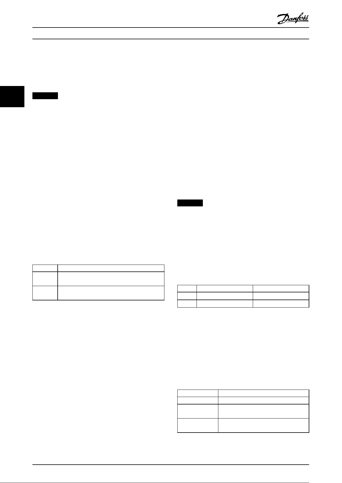
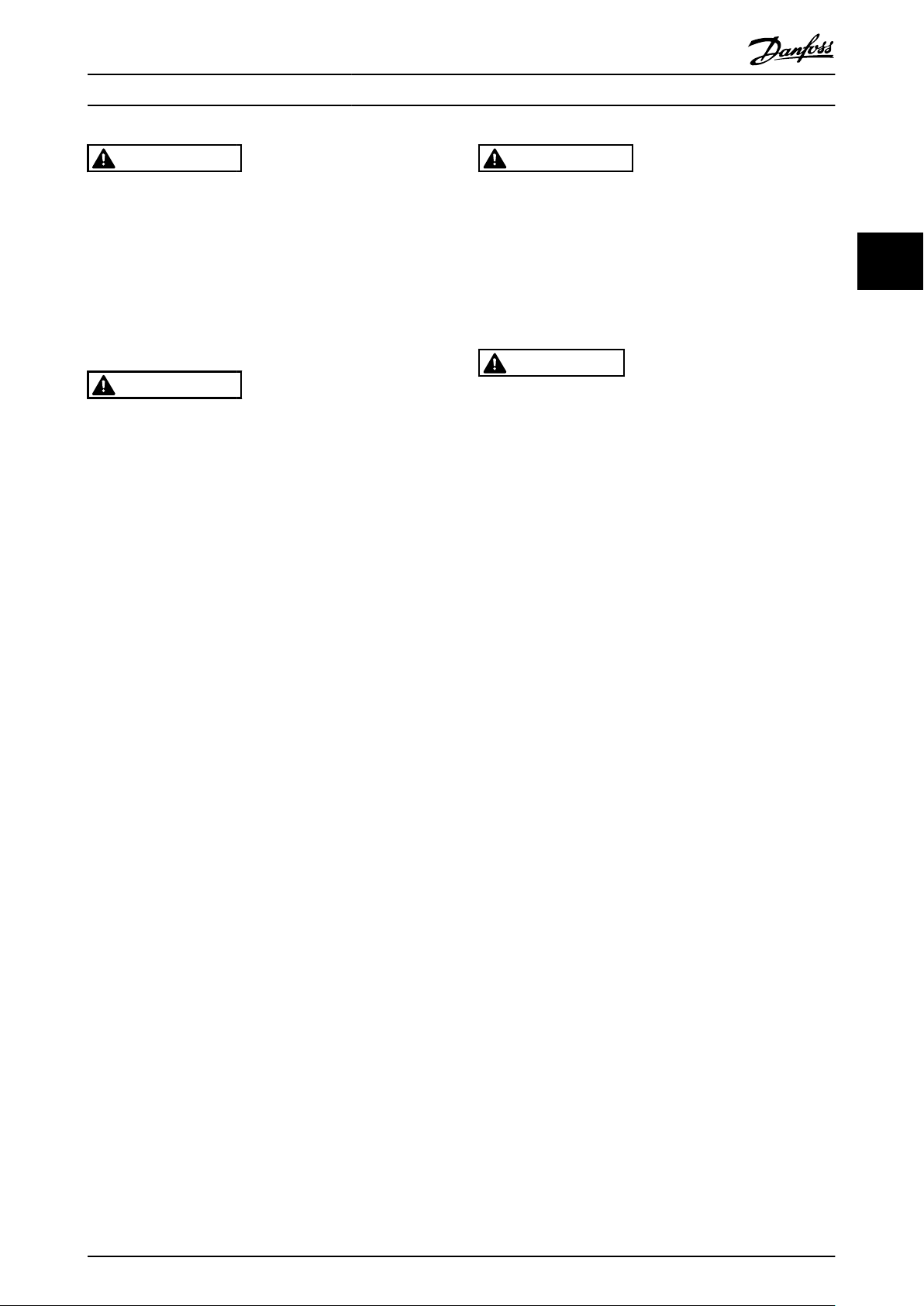
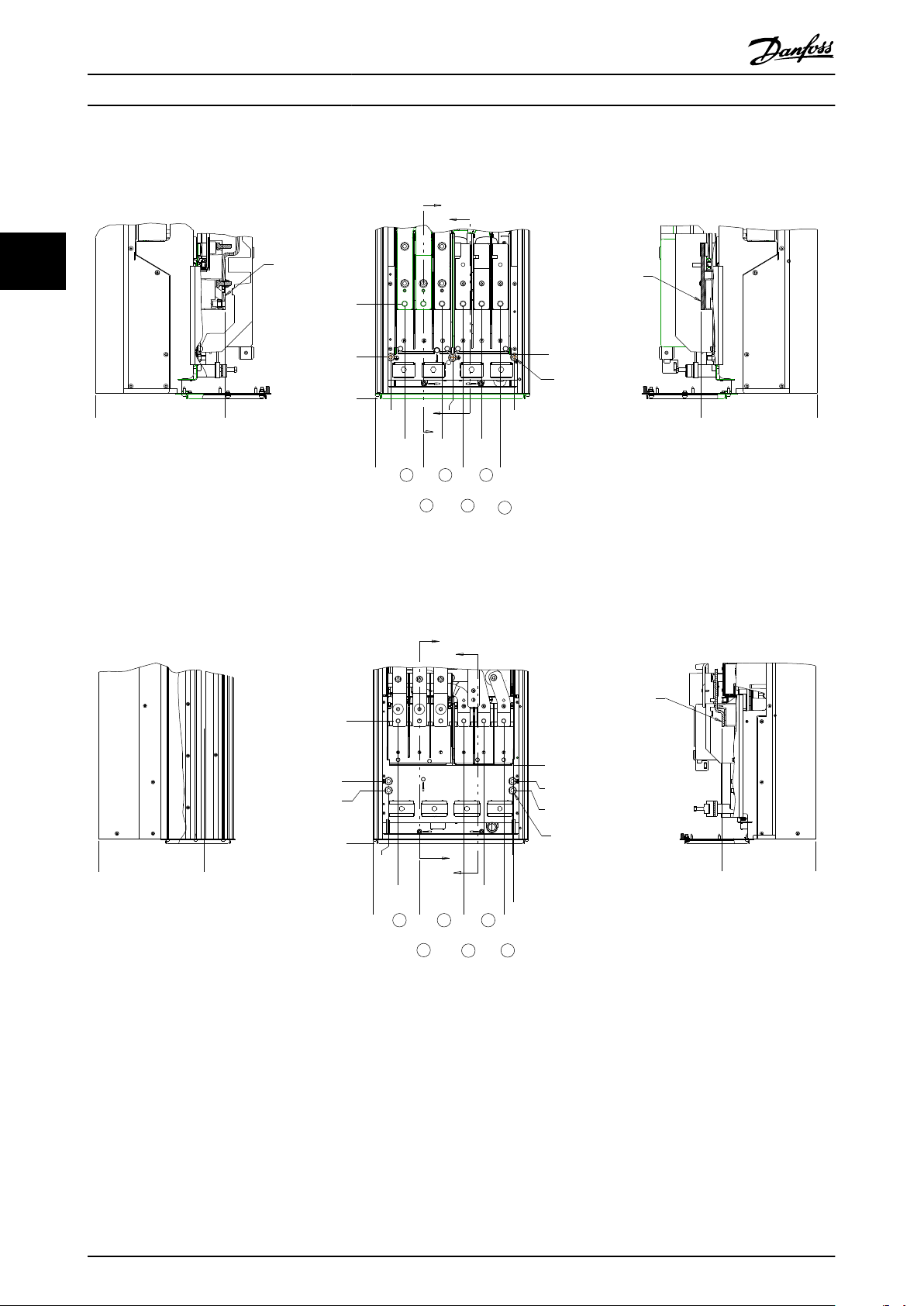
3.4.3.1 Terminal Locations
33
Illustration 3.5 Terminal Locations D1h
Illustration 3.6 Terminal Locations D2h
12 Danfoss A/S © 01/2015 All rights reserved. MG35Q202
Page 15

175HA036.11
U1V
1
W
1
96 97 98
FC
Motor
U
2V2
W
2
U1V
1
W
1
96 97 98
FC
Motor
U
2V2
W
2
130BC254.10
2
1
Installation
Installation Guide
3.4.4 Motor Cable
The motor must be connected to terminals U/T1/96, V/
T2/97, W/T3/98. Earth (ground) to terminal 99. The factory
setting is for clockwise rotation with the frequency
converter output connected as follows:
Terminal number Function
96, 97, 98,
99
Table 3.4 Terminals for Motor Cable Connection
Motor Rotation Check
3.4.5
The direction of rotation can be changed by switching 2
phases in the motor cable.
Terminal U/T1/96 connected
•
to U-phase
Terminal V/T2/97 connected
•
to V-phase
Terminal W/T3/98
•
connected to W-phase
Mains U/T1, V/T2, W/T3
Earth (ground)
1. Ground the cable in accordance with the
instructions provided.
2. Connect 3-phase AC input power wiring to
terminals L1, L2, and L3 (see Illustration 3.7).
3 3
Table 3.5 Wiring for Changing Motor Direction
AC Mains Connection
3.4.6
All frequency converters may be used with an
•
isolated input source as well as with ground
reference power lines. When supplied from an
isolated mains source (IT mains or floating delta)
or TT/TN-S mains with a grounded leg (grounded
delta), set 14-50 RFI Filter to [0] Off. When off, the
internal RFI filter capacitors between the chassis
and the intermediate circuit are isolated. Isolating
the capacitors prevents damage to the
intermediate circuit and reduces ground capacity
currents in accordance with IEC 61800-3.
Size wiring is based upon the input current of the
•
•
frequency converter.
Comply with local and national electrical codes
for cable sizes.
1 Mains connection
2 Motor connection
Illustration 3.7 Connecting to AC Mains
DC-Link Connection
3.4.7
Two field terminals are provided for connecting to the DCLink. The terminals are marked “+REGEN82” and “REGEN83”.
WARNING
REGEN TERMINALS
Frequency converters contain high voltage The REGEN
terminals must be connected to the correct polarity and
properly insulated from ground. Qualified personnel only
should perform installation, start up, and maintenance.
Failure to perform installation, start up, and maintenance
by qualified personnel could result in death or serious
injury.
MG35Q202 Danfoss A/S © 01/2015 All rights reserved. 13
Page 16

175ZA166.13
0,01 0,1 1 10 100 MHz
10
10
10
1
10
10
10
10
10
a
b
c
d
e
f
g
The lower the Z the better the cable screening performance
Transfer impedance, Z
t
mOhm/m
Installation
Danfoss Turbocor
WARNING
HIGH VOLTAGE
The DC-link of a frequency converter contains high
voltage when connected to AC mains input power.
Qualified personnel only should perform installation,
33
start-up, and maintenance. Failure to perform installation, start-up, and maintenance by qualified personnel
could result in death or serious injury.
Transfer impedance (Z
the following factors:
The conductibility of the screen material.
•
The contact resistance between the individual
•
screen conductors.
The screen coverage, i.e. the physical area of the
•
cable covered by the screen - often stated as a
percentage value.
Screen type, i.e. braided or twisted pattern.
•
) can be assessed on the basis of
T
WARNING
DISCHARGE TIME
Frequency converters contain DC-link capacitors that can
remain charged even when the frequency converter is
not powered. To avoid electrical hazards, disconnect AC
mains, any permanent magnet type motors, and any
remote DC-link power supplies, including battery backups, UPS, and DC-link connections to other frequency
converters. Wait for the capacitors to fully discharge
before performing any service or repair work. The
amount of wait time is listed in Table 2.1. Failure to wait
the specified time after power has been removed before
doing service or repair could result in death or serious
injury.
3.5 Control Wiring Connection
3.5.1
All terminals to the control cables are located on the inside
of the frequency converter. To access, open the door
(IP21).
3.5.2
Danfoss recommends braided screened/armoured cables to
optimise EMC immunity of the control cables and the EMC
emission from the motor cables.
The ability of a cable to reduce the incoming and
outgoing radiation of electric noise depends on the
transfer impedance (ZT). The screen of a cable is normally
designed to reduce the transfer of electric noise; however,
a screen with a lower transfer impedance (ZT) value is
more effective than a screen with a higher transfer
impedance (ZT).
Transfer impedance (ZT) is rarely stated by cable manufacturers, but it is often possible to estimate transfer
impedance (ZT) by assessing the physical design of the
cable.
Isolate control wiring from high power
•
components in the frequency converter
Access
Using Screened Control Cables
a Aluminium-clad with copper wire
b Twisted copper wire or armoured steel wire cable
c Single-layer braided copper wire with varying percentage
screen coverage (this is the typical Danfoss reference
cable).
d Double-layer braided copper wire
e Twin layer of braided copper wire with a magnetic,
screened/armoured intermediate layer
f Cable that runs in copper tube or steel tube
g Lead cable with 1.1 mm wall thickness
Illustration 3.8 Cable Screening Performance
Grounding of Screened Control
3.5.3
Cables
Correct screening
The preferred method in most cases is to secure control
and serial communication cables with screening clamps
provided at both ends to ensure best possible high
frequency cable contact. If the ground potential between
the frequency converter and the PLC is different, electric
noise may occur that disturbs the entire system. Solve this
14 Danfoss A/S © 01/2015 All rights reserved. MG35Q202
Page 17

1
2
PE
FC
PE
PLC
130BB922.12
PE PE
<10 mm
100nF
FC
PE
PE
PLC
<10 mm
130BB609.12
PE
FC
PE
FC
130BB923.12
PE PE
69
68
61
69
68
61
1
2
<10 mm
PE
FC
PE
FC
130BB924.12
PE PE
69
69
68
68
1
2
<10 mm
1
4
2
3
130BA012.12
61
68
69
39
42
50
53
54
55
12
13
18
19
27
29
32
33
20
37
Installation
Installation Guide
problem by fitting an equalizing cable next to the control
cable. Minimum cable cross section: 16 mm2.
1
Min. 16 mm
2 Equalizing cable
Illustration 3.9 Correct Screening
2
50/60 Hz ground loops
With very long control cables, ground loops may occur. To
eliminate ground loops, connect one end of the screen-toground with a 100 nF capacitor (keeping leads short).
Illustration 3.10 Avoiding Ground Loops
1
Min. 16 mm
2
2 Equalizing cable
Illustration 3.12 Screening without Using Terminal 61
3.5.4 Control Terminal Types
3 3
Avoid EMC noise on serial communication
This terminal is connected to ground via an internal RC
link. Use twisted-pair cables to reduce interference
between conductors. The recommended method is shown
below:
Illustration 3.13 Control Terminal Locations
Connector 1 provides four programmable digital
•
input terminals, two additional digital terminals
programmable as either input or output, a 24 V
1
Min. 16 mm
2
2 Equalizing cable
Illustration 3.11 Avoiding EMC Noise
DC terminal supply voltage, and a common for
optional customer supplied 24 V DC voltage
Connector 2 terminals (+)68 and (-)69 are for an
•
RS485 serial communications connection
Connector 3 provides 2 analog inputs, one
•
analog output, 10 V DC supply voltage, and
Alternatively, the connection to terminal 61 can be
omitted:
MG35Q202 Danfoss A/S © 01/2015 All rights reserved. 15
commons for the inputs and output
Connector 4 is a USB port available for use with
•
the MCT 10 Set-up Software
Also provided are 2 Form C relay outputs that are
•
located on the power card
Page 18

130BT306.10
130BT310.11
Installation Danfoss Turbocor
3.5.5 Wiring to Control Terminals
Terminal plugs can be removed for easy access.
33
Illustration 3.14 Removal of Control Terminals
3.6
Serial Communication
RS485 is a two-wire bus interface compatible with multidrop network topology.
Terminate each segment at both ends, using the
termination switch (S801) of the frequency converter.
Always use screened twisted pair (STP) cable for bus
cabling, and always follow good common installation
practice.
Low-impedance earth (ground) connection of the screen at
every node is important, including at high frequencies.
Thus, connect a large surface of the screen to earth
(ground), for example with a cable clamp or a conductive
cable gland. It may be necessary to apply potentialequalizing cables to maintain the same earth (ground)
potential throughout the network. Particularly in installations with long cables.
Cable Screened twisted pair (STP)
Impedance
Max. cable length
Table 3.6
120 Ω
1200 m (including drop lines)
500 m station-to-station
Illustration 3.15 Location of Bus Termination Switch
To run STO, additional wiring for the frequency converter
is required. Refer to VLT® Frequency Converters Safe Torque
Off Operating Instructions for further information.
16 Danfoss A/S © 01/2015 All rights reserved. MG35Q202
Page 19

Start Up and Commissioning
Installation Guide
4 Start Up and Commissioning
4.1 Pre-start
CAUTION
Before applying power to the unit, inspect the entire installation as detailed in Table 4.1. Check mark those items when
completed.
Inspect for Description
Auxiliary equipment
Cable routing
Control wiring
Cooling clearance
EMC considerations
Environmental considerations
Fusing and circuit
breakers
Grounding
Input and output power
wiring
Panel interior
Switches
Vibration
Look for auxiliary equipment, switches, disconnects, or input fuses/circuit breakers on the input
•
power side of the frequency converter or output side to the motor. Ensure that they are ready for
full speed operation.
Check function and installation of any sensors used for feedback to the frequency converter.
•
Remove power factor correction caps on motors, if present.
•
Use separate metallic conduits for each of the following:
•
-
-
-
Check for broken or damaged wires and loose connections.
•
Check that control wiring is isolated from power and motor wiring for noise immunity.
•
Check the voltage source of the signals, if necessary.
•
Use shielded or twisted pair cable. Ensure that the shield is terminated correctly.
•
Measure that top and bottom clearance is adequate to ensure proper air flow for cooling.
•
Check for proper installation regarding electromagnetic compatibility.
•
See equipment label for the maximum ambient operating temperature limits.
•
Humidity levels must be 5–95%, non-condensing.
•
Check for proper fusing or circuit breakers.
•
Check that all fuses are inserted firmly and in operational condition and that all circuit breakers are
•
in the open position.
The unit requires a ground wire from its chassis to the building ground.
•
Check for good ground connections that are tight and free of oxidation.
•
Grounding to conduit or mounting the back panel to a metal surface is not sufficient.
•
Check for loose connections.
•
Check that motor and mains are in separate conduit or separated screened cables.
•
Inspect that the unit interior is free of debris and corrosion.
•
Ensure that all switch and disconnect settings are in the proper positions.
•
Check that the unit is mounted solidly or that shock mounts are used, as necessary.
•
Check for an unusual amount of vibration.
•
Input power
Motor wiring
Control wiring
☑
4 4
Table 4.1 Start-up Checklist
MG35Q202 Danfoss A/S © 01/2015 All rights reserved. 17
Page 20

Start Up and Commissioning Danfoss Turbocor
4.2 Applying Power
WARNING
HIGH VOLTAGE!
Frequency converters contain high voltage when
connected to the energised DC bus. Only qualified
personnel should install, start up and maintain the
freqeuncy converters. Failure to let qualified personnel
44
install, start up and maintain the frequency converters
could result in death or serious injury.
WARNING
UNINTENDED START!
When the frequency converter is connected to the
energised DC bus, the motor may start at any time. The
frequency converter, motor, and any driven equipment
must be in operational readiness. Failure to be in
operational readiness when the frequency converter is
connected to the energised DC bus could result in death,
serious injury, equipment, or property damage.
1. Confirm input voltage is balanced within 3%. If
not, correct input voltage imbalance before
proceeding. Repeat procedure after voltage
correction.
2. Ensure optional equipment wiring, if present,
matches installation application.
3. Ensure that all operator devices are in the OFF
position. Panel doors closed, or a cover mounted.
4. Apply power to the unit. DO NOT start the
frequency converter now. For units with a
disconnect switch, turn to the ON position to
apply power to the frequency converter.
18 Danfoss A/S © 01/2015 All rights reserved. MG35Q202
Page 21

Specifications
Installation Guide
5 Specifications
5.1 Power-dependent Specifications
DTC 302 N165 N232 N262
Typical shaft output at 400 V [kW] 165 232 262
Typical shaft output at 460 V [hp] 221 311 352
Enclosure IP21 D1h D2h D2h
Output current
Continuous (at 400 V) [A] 318 424 480
Continuous (at 460 V) [A] 263 350 443
Continuous kVA (at 400 V) [kVA] 179 252 285
Continuous kVA (at 460 V) [kVA] 179 252 285
Max. input current
Continuous (at 400 V) [A] 271 380 430
Continuous (at 460 V) [A] 235 330 374
Max. cable size: mains, motor, mm (AWG) 2x95 (2x3/0 mcm) 2x185 (2x350 mcm) 2x185 (2x350 mcm)
Max. external mains fuses [A] 400 550 630
Estimated power loss at 400 V [W] 4271 5232 6203
Estimated power loss at 460 V [W] 3561 4390 5830
Efficiency 0.98
Output frequency [Hz] 0–590
Heat sink overtemperature trip [°F] ([°C])
Control card ambient trip [°F] ([°C])
158 (70) 149 (65) 149 (65)
230 (110)
5 5
Table 5.1 Mains Supply 3x380-500 V AC
DTC 302 N165 N232
Typical shaft output at 575 V [kW] 165 232
Typical shaft output at 575 V [hp] 221 311
Enclosure IP21 D1h D2h
Output current
Continuous (at 575 V) [A] 205 286
Continuous kVA (at 575 V) [kVA] 179 252
Max. input current
Continuous (at 575 V) [A] 188 264
Max. cable size: mains, motor, mm (AWG) 2x95 (2x3/0) 2x185 (2x350)
Max. external mains fuses [A] 315 550
Estimated power loss at 575 V [W] 3873 5288
Weight, enclosure IP21 kg (lbs.) 62 (135) 125 (275)
Efficiency 0.98
Output frequency [Hz] 0–590
Heat sink overtemperature trip [°F] ([°C])
Control card ambient trip [°F] ([°C])
Table 5.2 Mains Supply 3x575 V AC
The typical power loss is at nominal load conditions and expected to be within ±15% (tolerance relates to variety
•
167 (75) 176 (80)
230 (110)
in voltage and cable conditions).
The losses are based on the default switching frequency. The losses increase significantly at higher switching
•
frequencies.
MG35Q202 Danfoss A/S © 01/2015 All rights reserved. 19
Page 22

Specifications
Danfoss Turbocor
5.2 General Technical Data
Mains supply (L1, L2, L3)
Supply voltage 380-500 V ±10%, 575 V ±10%
Mains voltage low/mains voltage drop-out:
During low mains voltage or a mains drop-out, the frequency converters continues until the intermediate circuit voltage drops
below the minimum stop level, which corresponds typically to 15% below the frequency converter's lowest rated supply voltage.
Power-up and full torque cannot be expected at mains voltage lower than 10% below the frequency converter's lowest rated
supply voltage.
Supply frequency 50/60 Hz ±5%
Max. imbalance temporary between mains phases 3.0% of rated supply voltage
55
True Power Factor (λ) ≥0.9 nominal at rated load
Displacement Power Factor (cos Φ) near unity (>0.98)
Switching on input supply L1, L2, L3 (power ups) maximum one time/2 minutes
Environment according to EN60664-1 overvoltage category III/pollution degree 2
The unit is suitable for use on a circuit capable of delivering not more than 100,000 RMS symmetrical Amperes, 480/600 V
Motor Output (U, V, W)
Output voltage 0-100% of supply voltage
Output frequency 0-590 Hz*
Switching on output Unlimited
Ramp times 0.01-3600 s
* Dependent on voltage and power
Cable lengths and cross sections
Max. motor cable length, screened/armoured 150 m
Max. motor cable length, unscreened/unarmoured 300 m
Max. cross section to motor, mains*
Maximum cross section to control terminals, rigid wire 1.5 mm2/16 AWG (2x0.75 mm2)
Maximum cross section to control terminals, flexible cable 1 mm2/18 AWG
Maximum cross section to control terminals, cable with enclosed core 0.5 mm2/20 AWG
Minimum cross section to control terminals 0.25 mm
Digital inputs
Programmable digital inputs 4 (6)
Terminal number 18, 19, 271), 291), 32, 33
Logic PNP or NPN
Voltage level 0-24 V DC
Voltage level, logic '0' PNP <5 V DC
Voltage level, logic '1' PNP >10 V DC
Voltage level, logic '0' NPN >19 V DC
Voltage level, logic '1' NPN <14 V DC
Maximum voltage on input 28 V DC
Input resistance, R
All digital inputs are galvanically isolated from the supply voltage (PELV) and other high-voltage terminals.
1) Terminals 27 and 29 can also be programmed as output.
Control card, RS485 serial communication
Terminal number 68 (P,TX+, RX+), 69 (N,TX-, RX-)
Terminal number 61 Common for terminals 68 and 69
The RS485 serial communication circuit is functionally seated from other central circuits and galvanically isolated from the
supply voltage (PELV).
i
approx. 4 kΩ
2
20 Danfoss A/S © 01/2015 All rights reserved. MG35Q202
Page 23

Specifications Installation Guide
Control card, 24 V DC output
Terminal number 12, 13
Max. load 200 mA
The 24 V DC supply is galvanically isolated from the supply voltage (PELV ), but has the same potential as the analog and digital
inputs and outputs.
Control characteristics
Resolution of output frequency at 0-1000 Hz ±0.003 Hz
System response time (terminals 18, 19, 27, 29, 32, 33) ≤2 ms
Speed control range (open loop) 1:100 of synchronous speed
Speed accuracy (open loop) 30-4000 rpm: Maximum error of ±8 rpm
All control characteristics are based on a 4-pole asynchronous motor
Surroundings
Enclosure type D1h/D2h IP21/Type 1
Vibration test all enclosure types 0.7 g
Relative humidity 5%-95% (IEC 721-3-3; Class 3K3 (non-condensing) during operation
Aggressive environment (IEC 60068-2-43) H2S test
Test method according to IEC 60068-2-43 H2S (10 days)
Ambient temperature (at 60AVM switching mode)
- at full continuous FC output current max. 104 °F [40 °C]
class Kd
5 5
Minimum ambient temperature during full-scale operation 0 °C
Minimum ambient temperature at reduced performance - 10 °C
Temperature during storage/transport -25 to +65/70 °C
Maximum altitude above sea level without derating 1,000 m
Maximum altitude above sea level with derating 3,000 m
1) For more information on derating see the Design Guide, section on Special Conditions.
EMC standards, Emission EN 61800-3, EN 61000-6-3/4, EN 55011, IEC 61800-3
EN 61800-3, EN 61000-6-1/2,
EMC standards, Immunity
See the Design Guide, section on Special Conditions.
Control card performance
Scan interval 5 ms
Protection and Features
Electronic thermal motor protection against overload.
•
Temperature monitoring of the heat sink ensures that the frequency converter trips if the temperature reaches
•
95 °C ±5 °C. An overload temperature cannot be reset until the temperature of the heat sink is below 70 °C ±5 °C
(Guideline - these temperatures may vary for different power sizes, enclosures etc.).
The frequency converter is protected against short-circuits on motor terminals U, V, W.
•
If a mains phase is missing, the frequency converter trips or issues a warning (depending on the load).
•
Monitoring of the intermediate circuit voltage ensures that the frequency converter trips if the intermediate circuit
•
voltage is too low or too high.
The frequency converter is protected against earth (ground) faults on motor terminals U, V, W.
•
EN 61000-4-2, EN 61000-4-3, EN 61000-4-4, EN 61000-4-5, EN 61000-4-6
MG35Q202 Danfoss A/S © 01/2015 All rights reserved. 21
Page 24

Specifications Danfoss Turbocor
5.3 Fuse Tables
5.3.1 Protection
Branch circuit protection
In order to protect the installation against electrical and fire hazard, all branch circuits in an installation, switch gear,
machines etc., must be short-circuited and over-current protected according to national/international regulations.
Short-circuit protection
The frequency converter must be protected against short-circuit to avoid electrical or fire hazard. Danfoss recommends
using the fuses mentioned below to protect service personnel and equipment in case of an internal failure in the frequency
conveter. The frequency converter provides full short-circuit protection in case of a short-circuit on the motor output.
55
Over-current protection
Provide overload protection to avoid fire hazard due to overheating of the cables in the installation. The frequency
converter is equipped with an internal over-current protection that can be used for upstream overload protection (ULapplications excluded). Moreover, fuses or circuit breakers can be used to provide the over-current protection in the
installation. Over-current protection must always be carried out according to national regulations.
Fuse Selection
5.3.2
Danfoss recommends using the following fuses which ensures compliance with EN 50178. In case of malfunction, not
following the recommendation may result in unnecessary damage to the frequency converter.
The fuses below are suitable for use on a circuit capable of delivering 100,000 Arms (symmetrical).
N165, N232, N262
N165, N232 575 V type aR
Table 5.3 Recommended Fuses
VLT
Model
N165 T5 170M2621 LA50QS400-4 L50S-400 FWH-400A 20 610
N232 T5 170M4015 LA50QS500-4 L50S-500 FWH-500A 20 610
N262 T5 170M4016 LA50QS600-4 L50S-600 FWH-600A 20 610
Table 5.4 Fuse Options for 380–500 V Frequency Converters
Table 5.5 Fuse Options for 575 V Frequency Converters
BussmanPNLittelfuse PN LittelfusePNBussmannPNSiba PN Ferraz ShawmutPNFerraz Shawmut PN
VLT Model Bussmann PN Siba PN Ferraz Shawmut European PN Ferraz Shawmut North American PN
N165 T7 170M2619 20 610 31.315 6,9URD31D08A0315 A070URD31KI0315
N232 T7 170M4015 20 620 31.550 6,9URD32D08A0550 A070URD32KI0550
380–500 V type aR
31.400
31.550
31.630
Ferraz Shawmut PN
(Europe)
A50QS400-4 6,9URD31D08A0400 A070URD31KI0400
A50QS500-4 6,9URD31D08A0550 A070URD31KI0550
A50QS600-4 6,9URD31D08A0630 A070URD31KI0630
(North America)
For UL compliance, use the Bussmann 170M series.
22 Danfoss A/S © 01/2015 All rights reserved. MG35Q202
Page 25

Specifications Installation Guide
5.3.3 Short Circuit Current Rating (SCCR)
The Short Circuit Current Rating (SCCR) of the frequency
converters is 100,000 amps at all voltages (380–575 V).
5.3.4 Connection Tightening Torques
When tightening all electrical connections it is very
important to tighten with the correct torque. Too low or
too high torque results in a bad electrical connection. Use
a torque wrench to ensure correct torque. Always use a
torque wrench to tighten the bolts.
5 5
Frame
size
D1h Mains
D2h Mains
Table 5.6 Torque for Terminals
Terminal Torque [Nm (in-lbs)] Bolt
Motor
Load sharing
Regen
Earth (Ground)
Brake
Motor
Regen
Load sharing
Earth (ground)
Brake 8.5-20.5 (75-181) M8
size
19-40 (168-354) M10
8.5-20.5 (75-181) M8
19-40 (168-354) M10
MG35Q202 Danfoss A/S © 01/2015 All rights reserved. 23
Page 26

Index Danfoss Turbocor
Index
A
AC input............................................................................................... 4, 13
AC mains................................................................................................ 4, 5
AC mains connection.......................................................................... 13
AC waveform............................................................................................ 4
Airflow......................................................................................................... 6
Analog input.......................................................................................... 15
Analog output....................................................................................... 15
B
Block diagram........................................................................................... 4
C
Cable length........................................................................................... 20
Check list, pre-installation.................................................................... 6
Circuit breaker....................................................................................... 17
Conduit................................................................................................ 9, 17
Control cable.......................................................................................... 15
Control cable, screened..................................................................... 15
Control card performance................................................................. 21
Control card, 24 V DC output........................................................... 21
Control card, RS485 serial communication................................. 20
Control characteristic.......................................................................... 21
Control system......................................................................................... 4
Control terminal.................................................................................... 16
Control terminal type.......................................................................... 15
Control wiring........................................................................ 7, 9, 10, 17
Control wiring connection................................................................ 14
Cooling clearance................................................................................. 17
Cross section.......................................................................................... 20
Current rating........................................................................................... 6
D
DC current.................................................................................................. 4
Derating............................................................................................... 6, 21
Digital input..................................................................................... 15, 20
Discharge time......................................................................................... 5
Disconnect switch................................................................................ 18
E
Electrical installation.............................................................................. 7
Electrical noise....................................................................................... 10
EMC.............................................................................................. 15, 17, 21
Equalizing cable.................................................................................... 15
External command................................................................................. 4
External controller.................................................................................. 4
F
Feedback................................................................................................. 17
Floating delta......................................................................................... 13
Frequency converter block diagram................................................ 4
Full load current...................................................................................... 6
Functional testing................................................................................... 4
Fuse........................................................................................................... 17
Fusing................................................................................................... 9, 17
G
Ground connection....................................................................... 10, 17
Ground loop........................................................................................... 15
Ground wire..................................................................................... 10, 17
Grounded delta..................................................................................... 13
Grounding........................................................................................ 10, 17
Grounding hazard................................................................................ 10
Grounding, IP21/54 enclosure......................................................... 11
Grounding, screened control cable............................................... 15
H
Harmonic.................................................................................................... 4
I
IEC 61800-3............................................................................................. 21
Induced voltage....................................................................................... 9
Input current.......................................................................................... 13
Input power....................................................................... 4, 5, 7, 10, 17
Input voltage.......................................................................................... 18
Installation.............................................................................. 4, 9, 17, 18
Installation site......................................................................................... 6
Installation, electrical............................................................................. 7
Installation, mechanical........................................................................ 6
Isolated mains........................................................................................ 13
L
Leakage current (>3.5 mA)................................................................ 10
M
Mains........................................................................................................... 9
Mains supply (L1, L2, L3).................................................................... 20
Mechanical installation......................................................................... 6
Motor cable................................................................................. 9, 11, 13
Motor connection................................................................................. 11
24 Danfoss A/S © 01/2015 All rights reserved. MG35Q202
Page 27

Index Installation Guide
Motor current........................................................................................... 4
Motor output (U, V, W)........................................................................ 20
Motor power............................................................................................. 9
Motor protection.............................................................................. 9, 21
Motor rotation check.......................................................................... 13
Motor status.............................................................................................. 4
Motor wiring.................................................................................. 7, 9, 17
Mounting................................................................................................. 17
Multiple frequency converters.................................................... 9, 11
N
Noise isolation................................................................................... 7, 17
O
Open loop............................................................................................... 21
Optional equipment............................................................................ 18
Overload protection.......................................................................... 6, 9
P
PELV.................................................................................................... 14, 21
Power........................................................................................................ 10
Power connection................................................................................ 10
Power factor................................................................................ 4, 11, 17
Pre-installation check list..................................................................... 6
Product overview.................................................................................... 3
Programming........................................................................................... 4
Protection................................................................................................ 22
Protection, feature............................................................................... 21
STO............................................................................................................. 16
Supply voltage................................................................................ 14, 15
Surroundings......................................................................................... 21
System feedback..................................................................................... 4
T
Temperature limit................................................................................. 17
Terminal location, D1h....................................................................... 12
Terminal location, D2h....................................................................... 12
Thermal protection................................................................................ 5
Thermistor............................................................................................... 14
Thermistor control wiring................................................................. 14
Torque, terminal................................................................................... 23
Transient protection.............................................................................. 4
Trip function............................................................................................. 9
Troubleshooting...................................................................................... 4
W
Wire type, rating................................................................................... 10
Wiring, control terminal..................................................................... 16
R
Relay output........................................................................................... 15
Remote command.................................................................................. 4
Reset.......................................................................................................... 21
RFI filter.................................................................................................... 13
RMS current............................................................................................... 4
RS485........................................................................................................ 16
S
Safe torque off....................................................................................... 16
Screened control cable....................................................................... 15
Screened control cable, using.......................................................... 14
Serial communication............................................................. 4, 15, 16
Shielded cable................................................................................... 7, 17
Shielded wire............................................................................................ 9
Specification............................................................................................. 4
Start-up....................................................................................................... 4
MG35Q202 Danfoss A/S © 01/2015 All rights reserved. 25
Page 28

Danfoss can accept no responsibility for possible errors in catalogues, brochures and other printed material. Danfoss reserves the right to alter its products without notice. This also applies to
products already on order provided that such alterations can be made without subsequential changes being necessary in specifications already agreed. All trademarks in this material are property
of the respective companies. Danfoss and the Danfoss logotype are trademarks of Danfoss A/S. All rights reserved.
Danfoss A/S
Ulsnaes 1
DK-6300 Graasten
www.danfoss.com/drives
130R0572 MG35Q202 01/2015
*MG35Q202*
 Loading...