

Page 1
Service Manual - Revision G
®
Danfoss Turbocor® Twin-Turbine
Centrifugal Series Compressors
TTS, TGS, TTH, TGH Series Compressors
http://turbocor.danfoss.com
Page 2

This manual covers Major Revision "F" and later compressors. If you have a Major Revision "E" or earlier compressor, we suggest
downloading Service Manual Revision E from our website since there are some steps that are unique.
Page 3

Table of Contents
Chapter 1.0 Introduction ........................................................................................................................................................................ 15
1.1 Application ................................................................................................................................................................................................................................................................... 15
1.2 Purpose .........................................................................................................................................................................................................................................................................16
1.3 Organization ................................................................................................................................................................................................................................................................17
1.4 Commitment to Quality and the Environment ...............................................................................................................................................................................................18
1.5 Safety Summary ......................................................................................................................................................................................................................................................... 18
1.6 Precautions ..................................................................................................................................................................................................................................................................18
1.7 Refrigerant Type .........................................................................................................................................................................................................................................................18
1.8 Electrical Isolation......................................................................................................................................................................................................................................................19
1.9 Handling Static Sensitive Devices ........................................................................................................................................................................................................................ 20
1.10 DC Bus Test Harness Installation and Removal .............................................................................................................................................................................................22
1.11 Compressor Fasteners ........................................................................................................................................................................................................................................... 27
1.12 General O-ring Handling ...................................................................................................................................................................................................................................... 27
Chapter 2.0 Compressor Fundamentals ................................................................................................................................................ 31
2.1 Main Fluid Path ........................................................................................................................................................................................................................................................... 31
2.2 Motor and Power Electronics Cooling ................................................................................................................................................................................................................31
2.3 Capacity Control......................................................................................................................................................................................................................................................... 34
2.4 Compressor Energy and Signal Flow .................................................................................................................................................................................................................. 34
Chapter 3.0 Compressor Removal and Installation .............................................................................................................................. 41
3.1 Refrigerant Containment ........................................................................................................................................................................................................................................41
3.2 Compressor Removal ............................................................................................................................................................................................................................................... 41
3.3 Compressor Installation .......................................................................................................................................................................................................................................... 42
3.4 Compressor Replacement Considerations for Motor Cooling Adapter .................................................................................................................................................43
3.5 Exterior Connection Torque Specifications ...................................................................................................................................................................................................... 45
Chapter 4.0 Compressor Components ................................................................................................................................................... 51
4.1 Component Identification ...................................................................................................................................................................................................................................... 51
4.2 Compressor Covers ................................................................................................................................................................................................................................................... 56
4.3 Cooling Adapter ......................................................................................................................................................................................................................................................... 61
4.4 Compressor Interface Module .............................................................................................................................................................................................................................. 63
4.5 Compressor Interface Cable ..................................................................................................................................................................................................................................66
4.6 Compressor Controller Cable Harness ............................................................................................................................................................................................................... 67
4.7 Solenoids and Coils ................................................................................................................................................................................................................................................... 72
4.8 Interstage Pipe - TTH/TGH ......................................................................................................................................................................................................................................77
4.9 Compressor Housing End Cap .............................................................................................................................................................................................................................. 78
4.10 IGV ................................................................................................................................................................................................................................................................................80
4.11 Mains Plate Bracket ................................................................................................................................................................................................................................................ 93
4.12 3-Phase Main Voltage Input Terminal Block .................................................................................................................................................................................................. 95
4.13 Input Mains Bus Bars (Except TTS300/TGS230) ..........................................................................................................................................................................................103
4.14 Terminal Block Fuse Replacement ...................................................................................................................................................................................................................105
4.15 Soft Start ...................................................................................................................................................................................................................................................................107
4.16 SCR DC Bus Bar - TTS300/TGS230 ....................................................................................................................................................................................................................119
4.17 Soft Start SCR Gate Cable ...................................................................................................................................................................................................................................121
4.18 Soft Start AC/DC Harness ...................................................................................................................................................................................................................................124
4.19 Silicone-Controlled Rectifier ............................................................................................................................................................................................................................133
4.20 SCR Cooling Manifold ..........................................................................................................................................................................................................................................150
4.21 Snubber Capacitors ..............................................................................................................................................................................................................................................156
4.22 DC Capacitor Bus Bar Assembly .......................................................................................................................................................................................................................156
4.23 Inverter ......................................................................................................................................................................................................................................................................165
4.24 Motor Components ..............................................................................................................................................................................................................................................191
4.25 High Voltage DC-DC Converter ........................................................................................................................................................................................................................201
4.26 Backplane .................................................................................................................................................................................................................................................................207
4.27 Serial Driver .............................................................................................................................................................................................................................................................212
4.28 BMCC .........................................................................................................................................................................................................................................................................214
4.29 Bearing Pulse Width Modulator Amplifier....................................................................................................................................................................................................218
4.30 Magnetic Bearings ................................................................................................................................................................................................................................................223
4.31 Bearing Sensors .....................................................................................................................................................................................................................................................228
4.32 Cavity Temperature Sensor ................................................................................................................................................................................................................................231
4.33 Pressure/Temperature Sensor ..........................................................................................................................................................................................................................234
Chapter 5.0 Troubleshooting ...............................................................................................................................................................241
5.1 Alarm and Fault Indications .................................................................................................................................................................................................................................241
5.2 Troubleshooting with the Service Monitoring Tools Software ...............................................................................................................................................................243
5.3 Bearing Calibration .................................................................................................................................................................................................................................................250
5.4 Compressor Connection Status Indications...................................................................................................................................................................................................255
5.5 System and Compressor Level Troubleshooting ..........................................................................................................................................................................................255
M-SV-001-EN Rev. G
3 of 282
Page 4

Table of Contents
Chapter 6.0 Maintenance ......................................................................................................................................................................263
6.1 Preventative Maintenance Tasks ......................................................................................................................................................................................................................263
6.2 Moisture Prevention Measures .........................................................................................................................................................................................................................264
Appendix A – Acronyms/Terms ........................................................................................................................................................... 269
Appendix B – Compressor Troubleshooting Flowcharts ................................................................................................................... 271
Appendix C – Compressor Test Sheet ................................................................................................................................................. 277
4 of 282 M-SV-001-EN Rev. G
Page 5

List of Tables
Table 2-1 Compressor Fluid Paths ...............................................................................................................................................................................................................................31
Table 3-1 Exterior Connection Torque Specifications ...................................................................................................................................................................................... 45
Table 4-1 Compressor Components (Covers On) ..................................................................................................................................................................................................51
Table 4-2 Compressor Components Service Side (Excludes TTH/TGH Compressors) .............................................................................................................................52
Table 4-3 Compressor Components Service Side (TTH/TGH Only) ................................................................................................................................................................53
Table 4-4 Compressor Components Capacitor Side (Excludes TTH/TGH) .................................................................................................................................................... 54
Table 4-5 Compressor Components Capacitor Side (TTH/TGH Only) ............................................................................................................................................................55
Table 4-6 Compressor Cover Torque Specifications ............................................................................................................................................................................................. 60
Table 4-7 Cooling Adapter Torque Specifications ................................................................................................................................................................................................. 62
Table 4-8 CIM Ports and Jumpers ................................................................................................................................................................................................................................63
Table 4-9 Compressor Controller Cable Harness Torque Specifications ....................................................................................................................................................... 72
Table 4-10 Solenoid Coil Resistance Ranges ........................................................................................................................................................................................................... 73
Table 4-11 Solenoid Torque Specifications .............................................................................................................................................................................................................. 76
Table 4-12 Interstage Pipe Torque Specifications ................................................................................................................................................................................................. 78
Table 4-13 Compressor Housing End Cap Torque Specifications .................................................................................................................................................................... 79
Table 4-14 IGV Components ......................................................................................................................................................................................................................................... 80
Table 4-15 IGV Feedthrough Wiring Order .............................................................................................................................................................................................................. 84
Table 4-16 IGV Feedthrough Pin to Wire Reference .............................................................................................................................................................................................90
Table 4-17 IGV Torque Specifications.........................................................................................................................................................................................................................92
Table 4-18 Mains Plate Torque Specifications......................................................................................................................................................................................................... 95
Table 4-19 Expected AC Voltage Range ....................................................................................................................................................................................................................98
Table 4-20 Terminal Block Torque Specifications ................................................................................................................................................................................................103
Table 4-21 AC Bus Bar Torque Specifications ........................................................................................................................................................................................................105
Table 4-22 Terminal Block Fuse Torque Specifications ......................................................................................................................................................................................107
Table 4-23 Closed-Top Soft Start Connection Identification ...........................................................................................................................................................................108
Table 4-24 Open-Top Soft Start Connection Identification .............................................................................................................................................................................109
Table 4-25 Soft Start Fuse Details .............................................................................................................................................................................................................................112
Table 4-26 Soft Start Torque Specifications ...........................................................................................................................................................................................................119
Table 4-27 SCR DC Bus Bar Torque Specifications ...............................................................................................................................................................................................121
Table 4-28 Soft Start AC/DC Harness Torque Specifications ...........................................................................................................................................................................133
Table 4-29 SCR Diode Values ......................................................................................................................................................................................................................................137
Table 4-30 SCR Gate Resistance Ranges .................................................................................................................................................................................................................137
Table 4-31 SCR Temperature Sensor Torque Specifications ............................................................................................................................................................................141
Table 4-32 SCR Torque Specifications ......................................................................................................................................................................................................................149
Table 4-33 SCR Cooling Manifold Torque Specifications. .................................................................................................................................................................................155
Table 4-34 DC Capacitor Bus Bar Assembly Torque Specifications ...............................................................................................................................................................164
Table 4-35 Inverter Cable Harness Torque Specifications ................................................................................................................................................................................168
Table 4-36 Spring Identification Table .....................................................................................................................................................................................................................189
Table 4-37 Inverter Torque Specifications ..............................................................................................................................................................................................................190
Table 4-38 Motor Assembly Torque Specifications .............................................................................................................................................................................................200
Table 4-39 DC-DC Torque Specifications ................................................................................................................................................................................................................206
Table 4-40 Backplane Connections ..........................................................................................................................................................................................................................208
Table 4-41 Backplane Test Points ..............................................................................................................................................................................................................................209
Table 4-42 Backplane LED Locations .......................................................................................................................................................................................................................210
Table 4-43 Backplane Test Point Values ..................................................................................................................................................................................................................211
Table 4-44 Backplane Torque Specifications .........................................................................................................................................................................................................212
Table 4-45 PWM Torque Specifications ...................................................................................................................................................................................................................222
Table 4-46 Magnetic Bearing Coil Resistance Values .........................................................................................................................................................................................224
Table 4-47 Bearing Amperage Nominal Ranges ..................................................................................................................................................................................................225
Table 4-48 Magnetic Bearing Torque Specifications ..........................................................................................................................................................................................228
Table 4-49 Bearing Sensor Coil Resistance ............................................................................................................................................................................................................229
Table 4-50 Bearing Sensor Torque Specifications ...............................................................................................................................................................................................231
Table 4-51 Cavity Sensor Torque Specifications ..................................................................................................................................................................................................233
Table 4-52 Pressure/Temperature Sensor Torque Specifications...................................................................................................................................................................237
Table 5-1 Alarm Types ...................................................................................................................................................................................................................................................241
Table 5-2 Compressor Fault Types ............................................................................................................................................................................................................................241
Table 5-3 Compressor Status 2 Faults ......................................................................................................................................................................................................................242
Table 5-4 Motor Fault Types ........................................................................................................................................................................................................................................243
Table 5-5 Bearing Fault Types .....................................................................................................................................................................................................................................243
Table 5-6 Compressor Status ......................................................................................................................................................................................................................................245
Table 5-7 Compressor Status 2 Faults ......................................................................................................................................................................................................................247
Table 5-8 Motor Status ..................................................................................................................................................................................................................................................248
Table 5-9 Bearing Status ...............................................................................................................................................................................................................................................250
Table 6-1 Preventative Maintenance Tasks ............................................................................................................................................................................................................263
Table 6-2 SCR Fastener Torque Specifications ......................................................................................................................................................................................................267
Table A-1 Acronyms/Terms .........................................................................................................................................................................................................................................269
M-SV-001-EN Rev. G
5 of 282
Page 6

List of Figures
Figure 2-1 Compressor Fluid Paths .............................................................................................................................................................................................................................31
Figure 2-2 Cooling Inlet Adapter .................................................................................................................................................................................................................................32
Figure 2-3 Split Cooling Path - TTH375/TGH285 ...................................................................................................................................................................................................33
Figure 2-4 Split Cooling Path - (TTS/TGS (Except TTS300/TGS230 Serial Cooling) ....................................................................................................................................33
Figure 2-5 Serial Cooling Path - TTS300/TGS230 ...................................................................................................................................................................................................34
Figure 2-6 Compressor Energy and Signal Flow Connections .........................................................................................................................................................................36
Figure 2-7 Compressor Energy and Control Flow Block Diagram - TTS/TGS Compressors .................................................................................................................... 37
Figure 3-1 Compressor Power Cable Removal .......................................................................................................................................................................................................41
Figure 3-2 Compressor Mounting Fasteners...........................................................................................................................................................................................................42
Figure 3-3 Motor Cooling Fitting.................................................................................................................................................................................................................................43
Figure 4-1 Compressor Components Identification (Covers On) ....................................................................................................................................................................51
Figure 4-2 Compressor Component Identification - Service Side (Excludes TTH/TGH Compressors) ...............................................................................................52
Figure 4-3 Compressor Component Identification - Service Side (TTH/TGH Only) .................................................................................................................................. 53
Figure 4-4 Compressor Component Identification - Capacitor Side (Excludes TTH/TGH) ......................................................................................................................54
Figure 4-5 Compressor Component Identification - Capacitor Side (TTH/TGH Only) ............................................................................................................................. 55
Figure 4-6 Top Covers Removal ...................................................................................................................................................................................................................................56
Figure 4-7 Mains Input Cover Torque Sequence ................................................................................................................................................................................................... 57
Figure 4-8 Top Cover ........................................................................................................................................................................................................................................................ 57
Figure 4-9 Service Side Cover ....................................................................................................................................................................................................................................... 58
Figure 4-10 Service Side Cover .................................................................................................................................................................................................................................... 58
Figure 4-11 Capacitor Cover ......................................................................................................................................................................................................................................... 59
Figure 4-12 Capacitor Nylon Nuts ...............................................................................................................................................................................................................................59
Figure 4-13 Relief Membrane Position ...................................................................................................................................................................................................................... 60
Figure 4-14 Recessed Holes .......................................................................................................................................................................................................................................... 60
Figure 4-15 Capacitor Cover Torque Sequence...................................................................................................................................................................................................... 60
Figure 4-16 Cooling Adapter - Excludes TTH375/TGH285 .................................................................................................................................................................................61
Figure 4-17 Cooling Adapter - TTH375/TGH285) ..................................................................................................................................................................................................61
Figure 4-18 Compressor Interface Module Ports & Jumpers ............................................................................................................................................................................ 63
Figure 4-19 Removing the Compressor Interface Module from the DIN Rail ............................................................................................................................................. 66
Figure 4-20 Compressor Interface Cable ..................................................................................................................................................................................................................67
Figure 4-21 Compressor Controller Cable Harness Variants..............................................................................................................................................................................68
Figure 4-22 Backplane Connections .......................................................................................................................................................................................................................... 69
Figure 4-23 Pressure/Temperature and SCR Temperature Sensor Locations - TTS300/TGS230 ...........................................................................................................69
Figure 4-24 Pressure/Temp and SCR Temp Sensor Locations - TTS/TGS .......................................................................................................................................................70
Figure 4-25 Pressure/Temperature Sensors - TTH375/TGH285 ........................................................................................................................................................................ 70
Figure 4-26 IGV Connector Clamp .............................................................................................................................................................................................................................. 70
Figure 4-27 Cable Passage ............................................................................................................................................................................................................................................. 71
Figure 4-28 Cooling Valve Bodies ...............................................................................................................................................................................................................................72
Figure 4-29 Compressor Cooling Solenoid Coils ................................................................................................................................................................................................... 72
Figure 4-30 Solenoid Coil Harness ..............................................................................................................................................................................................................................73
Figure 4-31 Backplane - J16 Connector .................................................................................................................................................................................................................... 73
Figure 4-32 Compressor Cooling Solenoid Coil Cable Connector .................................................................................................................................................................. 74
Figure 4-33 Backplane - Cool LEDs and +24V Test Points .................................................................................................................................................................................. 74
Figure 4-34 Solenoid Cooling Path - TTS300/TGS230 ..........................................................................................................................................................................................74
Figure 4-35 Solenoid Component Removal ............................................................................................................................................................................................................ 75
Figure 4-36 Solenoid Actuator Coil Position ........................................................................................................................................................................................................... 76
Figure 4-37 Interstage Pipe ........................................................................................................................................................................................................................................... 77
Figure 4-38 Interstage Pipe Removal .........................................................................................................................................................................................................................77
Figure 4-39 Compressor Housing End Cap - TTS/TGS .........................................................................................................................................................................................78
Figure 4-40 Compressor Housing End Cap - TTH/TGH ........................................................................................................................................................................................78
Figure 4-41 IGV Assembly .............................................................................................................................................................................................................................................. 80
Figure 4-42 IGV Connections ........................................................................................................................................................................................................................................ 80
Figure 4-43 IGV Motor Feedthrough ..........................................................................................................................................................................................................................81
Figure 4-44 SMT Icon ....................................................................................................................................................................................................................................................... 81
Figure 4-45 Compressor Configuration Tool ........................................................................................................................................................................................................... 81
Figure 4-46 Control Mode..............................................................................................................................................................................................................................................82
Figure 4-47 Compressor Monitor Tool.......................................................................................................................................................................................................................82
Figure 4-48 IGV Open Percentage - 100% ................................................................................................................................................................................................................ 82
Figure 4-49 IGV Open Percentage - 0%.....................................................................................................................................................................................................................82
Figure 4-50 Backplane Cool LEDs ............................................................................................................................................................................................................................... 83
Figure 4-51 Backplane +15V Test Point .....................................................................................................................................................................................................................83
Figure 4-52 IGV Harness Removal ...............................................................................................................................................................................................................................83
Figure 4-53 IGV Housing Removal .............................................................................................................................................................................................................................. 84
Figure 4-54 IGV Feedthrough Removal.....................................................................................................................................................................................................................84
Figure 4-55 Set Screw Removal ................................................................................................................................................................................................................................... 85
Figure 4-56 IGV Motor Assembly Removal .............................................................................................................................................................................................................. 85
Figure 4-57 Locking Collar Tool ...................................................................................................................................................................................................................................85
6 of 282 M-SV-001-EN Rev. G
Page 7

List of Figures
Figure 4-58 Locking Collar Removal .......................................................................................................................................................................................................................... 86
Figure 4-59 Worm Gear Removal ................................................................................................................................................................................................................................86
Figure 4-60 Large Worm Gear Bearing Removal ...................................................................................................................................................................................................86
Figure 4-61 IGV Throat Removal ..................................................................................................................................................................................................................................87
Figure 4-62 Small Worm Gear Bearing Removal ....................................................................................................................................................................................................87
Figure 4-63 Small Worm Gear Bearing Installation ............................................................................................................................................................................................... 87
Figure 4-64 IGV Position Indicator Magnet ............................................................................................................................................................................................................. 88
Figure 4-65 Large Worm Gear Bearing Installation...............................................................................................................................................................................................88
Figure 4-66 Locking Collar Installation ..................................................................................................................................................................................................................... 89
Figure 4-67 IGV Worm Gear Alignment ....................................................................................................................................................................................................................89
Figure 4-68 Shaft Position ..............................................................................................................................................................................................................................................89
Figure 4-69 IGV Motor Alignment ...............................................................................................................................................................................................................................90
Figure 4-70 Motor Wire Position ..................................................................................................................................................................................................................................90
Figure 4-71 IGV Motor Wires Connected ..................................................................................................................................................................................................................91
Figure 4-72 Feedthrough Orientation ....................................................................................................................................................................................................................... 91
Figure 4-73 IGV Housing Installation ......................................................................................................................................................................................................................... 91
Figure 4-74 IGV Position Indicator .............................................................................................................................................................................................................................. 92
Figure 4-75 Mains Plate Bracket .................................................................................................................................................................................................................................. 93
Figure 4-76 Ground Post Nuts ...................................................................................................................................................................................................................................... 94
Figure 4-77 Mains Input Nut Installation - TTS300/TGS230 Compressors ................................................................................................................................................... 94
Figure 4-78 Mains Input Nut Installation - TTS/TGS/TTH/TGH Rev. H and Earlier (Except TTS300/TGS230) ...................................................................................94
Figure 4-79 Input Terminal Block - TTS300/TGS230 ............................................................................................................................................................................................. 95
Figure 4-80 Input Terminal Block - TTS/TGS/TTH/TGH Rev. H (Except TTS300/TGS230) .........................................................................................................................96
Figure 4-81 Input Terminal Block - TTS/TGS/TTH/TGH Rev. F and Earlier (Except TTS300/TGS230) ....................................................................................................96
Figure 4-82 Measuring the 3-Phase AC Input Voltage on the AC Input Terminals - TTS300/TGS230 .................................................................................................97
Figure 4-83 Measuring 3-Phase AC Input Voltage on AC Input Terminals (TTS/TGS/TTH/TGH (Except TTS300/TGS230) ..........................................................97
Figure 4-84 Terminal Block Removal - TTS300/TGS230 ....................................................................................................................................................................................... 98
Figure 4-85 Input Terminal Block Removal - TTS/TGS/TTH/TGH Rev. F and Earlier (Except TTS300/TGS230) ................................................................................99
Figure 4-86 Input Terminal Block Removal - TTS/TGS/TTH/TGH Rev. H (Except TTS300/TGS230) ....................................................................................................100
Figure 4-87 Input Terminal Block Installation - TTS300/TGS230 ....................................................................................................................................................................100
Figure 4-88 Terminal Block - Input Pressure Screws - TTS300/TGS230 ........................................................................................................................................................101
Figure 4-89 Input Terminal Block Installation - TTS/TGS/TTH/TGH Rev. F and Earlier (Except TTS300/TGS230) ..........................................................................101
Figure 4-90 Input Terminal Block Installation - TTS/TGS/TTH/TGH Rev. H (Except TTS300/TGS230) ..............................................................................................102
Figure 4-91 Input Mains Bus Bar Examples ...........................................................................................................................................................................................................103
Figure 4-92 AC/DC Bus Bus Bar Connectors - TTS/TGS/TTH/TGS Rev. F and earlier (Except TTS300/TGH230) .............................................................................104
Figure 4-93 AC/DC Bus Bus Bar Connectors - TTS/TGS/TTH/TGS Rev. H (Except TTS300/TGH230) ...................................................................................................104
Figure 4-94 Terminal Block Fuse ................................................................................................................................................................................................................................105
Figure 4-95 Terminal Block Fuse Test .......................................................................................................................................................................................................................106
Figure 4-96 Terminal Block Fuse Removal..............................................................................................................................................................................................................106
Figure 4-97 Soft Start Variants....................................................................................................................................................................................................................................107
Figure 4-98 Closed-Top Soft Start Connections ...................................................................................................................................................................................................108
Figure 4-99 Open-Top Soft Start Connections .....................................................................................................................................................................................................109
Figure 4-100 Soft Start Label Location ....................................................................................................................................................................................................................110
Figure 4-101 Soft Start Fuse Locations ...................................................................................................................................................................................................................111
Figure 4-102 Closed-Top Soft Start J9 Connector ...............................................................................................................................................................................................112
Figure 4-103 Ground Location ...................................................................................................................................................................................................................................113
Figure 4-104 Closed-Top Soft Start ...........................................................................................................................................................................................................................113
Figure 4-105 Soft Start Lift...........................................................................................................................................................................................................................................113
Figure 4-106 Closed-Top Soft Start Connector Removal ..................................................................................................................................................................................114
Figure 4-107 Open-Top Soft Start J7 Connector ..................................................................................................................................................................................................114
Figure 4-108 Ground Location ...................................................................................................................................................................................................................................114
Figure 4-109 Open-Top Soft Start Connector Removal ....................................................................................................................................................................................115
Figure 4-110 Open-Top Soft Start Removal ...........................................................................................................................................................................................................115
Figure 4-111 Closed-Top-Soft Start Installation ...................................................................................................................................................................................................116
Figure 4-112 Ground Stud Location .........................................................................................................................................................................................................................116
Figure 4-113 Open-Top-Soft Start Installation .....................................................................................................................................................................................................117
Figure 4-114 Soft Start without Adapter ................................................................................................................................................................................................................118
Figure 4-115 Soft Start Fan Orientation ..................................................................................................................................................................................................................118
Figure 4-116 Soft Start Fan Installation ..................................................................................................................................................................................................................118
Figure 4-117 Soft Start Fan Connector ....................................................................................................................................................................................................................119
Figure 4-118 SCR DC Bus Bars ....................................................................................................................................................................................................................................119
Figure 4-119 SCR DC Bus Bar Removal - TTS300/TGS230 .................................................................................................................................................................................120
Figure 4-120 SCR DC Bus Bar to SCR Alignment ..................................................................................................................................................................................................120
Figure 4-121 Soft Start SCR Gate Cable (Closed-Top Soft Starts)...................................................................................................................................................................121
Figure 4-122 Soft Start SCR Gate Cable (Open-Top Soft Starts) .....................................................................................................................................................................121
Figure 4-123 Soft Start SCR Gate Cable Removal - TTS300/TGS230 .............................................................................................................................................................122
Figure 4-124 Soft Start SCR Gate Cable Removal at SCR - TTS/TGS/TTH/TGH Models Rev. F and Earlier (Except TTS300/TGS230) ......................................122
M-SV-001-EN Rev. G
7 of 282
Page 8

List of Figures
Figure 4-125 Soft Start SCR Gate Cable Removal at SCR - TTS/TGS/TTH/TGH Models Rev. H (Except TTS300/TGS230) ...........................................................122
Figure 4-126 Closed-Top Soft Start J8 Connector Top .......................................................................................................................................................................................123
Figure 4-127 Open-Top Soft Start J2 Connector ..................................................................................................................................................................................................123
Figure 4-128 SCR Gate Connector Alignment ......................................................................................................................................................................................................124
Figure 4-129 Soft Start AC/DC Harness Connections - TTS300/TGS230 .....................................................................................................................................................125
Figure 4-130 Soft Start AC/DC Harness Connections - TTS/TGS/TTH/TGH (Except TTS300/TGS230) .............................................................................................126
Figure 4-131 AC Input Ring Terminal Removal - TTS300/TGS230 .................................................................................................................................................................127
Figure 4-132 DC Ring Terminal Removal - TTS300/TGS230 .............................................................................................................................................................................127
Figure 4-133 DC-DC Connectors (Open Frame) ...................................................................................................................................................................................................127
Figure 4-134 DC-DC Connectors (Potted) ..............................................................................................................................................................................................................128
Figure 4-135 Closed-Top Soft Start J1 and J7 Removal .....................................................................................................................................................................................128
Figure 4-136 Open-Top Soft Start J1 and J8 Removal .......................................................................................................................................................................................129
Figure 4-137 AC Input Spade and DC Spade Connector Removal - TTS/TGS/TTH/TGH Rev. F and Earlier (Except TTS300/TGS230) ...................................129
Figure 4-138 AC Input Ring and DC Spade Connector Removal - TTS/TGS/TTH/TGH Rev. H (Except TTS300/TGS230) ............................................................130
Figure 4-139 Soft Start AC/DC Harness Position - TTS300/TGS230 ..............................................................................................................................................................131
Figure 4-140 AC Input and Spade Connector Installation - TTS/TGS/TTH/TGH Rev. F and Earlier (Except TTS300/TGS230) ..................................................132
Figure 4-141 AC Input and Spade Connector Installation - TTS/TGS/TTH/TGH Rev. H (Except TTS300/TGS230) ........................................................................133
Figure 4-142 SCR Styles ................................................................................................................................................................................................................................................134
Figure 4-143 SCR Connections - TTS300/TGS230 ................................................................................................................................................................................................134
Figure 4-144 SCR Connections - TTS/TGS/TTH/TGH Rev. F and Earlier (Except TTS300/TGS230) .....................................................................................................135
Figure 4-145 SCR Connections - TTS/TGS/TTH/TGH Rev. H (Except TTS300/TGS230) ...........................................................................................................................135
Figure 4-146 SCR Terminals - Two Hole Mount ....................................................................................................................................................................................................136
Figure 4-147 SCR Terminals - Four Hole Mount ...................................................................................................................................................................................................136
Figure 4-148 SCR Temperature Sensor Assembly ...............................................................................................................................................................................................137
Figure 4-149 J17 Connector ........................................................................................................................................................................................................................................137
Figure 4-150 Discharge Pressure/Temperature Sensor Connector Removal - TTS300/TGS230 .........................................................................................................138
Figure 4-151 SCR Temperature Sensor Connector - TTS300/TGS230 .........................................................................................................................................................138
Figure 4-152 SCR Temperature Sensor Removal -TTS300/TGS230 ..............................................................................................................................................................139
Figure 4-153 SCR Temperature Sensor Connector - TTS/TGS/TTH/TGH Rev. F and Earlier (Except TTS300/TGS230) .................................................................139
Figure 4-154 Discharge Pressure/Temperature Sensor Connector Removal - TTS/TGS/TTH/TGH (Except TTS300/TGS230) ..................................................139
Figure 4-155 SCR Temperature Sensor Removal - TTS/TGS/TTH/TGH Rev. F and Earlier (Except TTS300/TGS230).....................................................................140
Figure 4-156 Fuse Block Assemblies - Two Hole Mount - TTS300/TGS230 .................................................................................................................................................142
Figure 4-157 DC Bus Bar Removal - TTS300/TGS230..........................................................................................................................................................................................142
Figure 4-158 SCR Removal - TTS300/TGS230........................................................................................................................................................................................................143
Figure 4-159 SCR Gate Cable and AC/DC Harness Connections - TTS/TGS/TTH/TGH Rev. F and Earlier (Except TTS300/TGS230) .......................................143
Figure 4-160 SCR Gate Cable and AC/DC Harness Connections - TTS/TGS/TTH/TGH Rev. H (Except TTS300/TGS230) ..........................................................144
Figure 4-161 SCR Bus Fastener Removal - TTS/TGS/TTH/TGH Rev. F and Earlier (Except TTS300/TGS230)....................................................................................144
Figure 4-162 SCR Bus Fastener Removal - TTS/TGS/TTH/TGH Rev. H (Except TTS300/TGS230) ........................................................................................................145
Figure 4-163 SCR Removal - TTS/TGS/TTH/TGH Rev. F and Earlier (Except TTS300/TGS230) .............................................................................................................145
Figure 4-164 SCR Removal - TTS/TGS/TTH/TGH Rev. H (Except TTS300/TGS230) ..................................................................................................................................145
Figure 4-165 SCR Heat Sink Paste Application - TTS300/TGS230 ..................................................................................................................................................................146
Figure 4-166 SCR Orientation - TTS300/TGS230 ..................................................................................................................................................................................................146
Figure 4-167 Bus Bar Installation - TTS300/TGS230 ............................................................................................................................................................................................147
Figure 4-168 Bus Bar Locations - TTS300/TGS230 ...............................................................................................................................................................................................147
Figure 4-169 SCR Thermal Paste Application - TTS/TGS/TTH/TGH (Except TTS300/TGS230) .............................................................................................................148
Figure 4-170 SCR Torque Sequence - TTS/TGS/TTH/TGH Rev. F and Earlier (Except TTS300/TGS230)............................................................................................148
Figure 4-171 SCR Cooling Manifold .........................................................................................................................................................................................................................150
Figure 4-172 Inverter Assembly Removal - TTS300/TGS230 ...........................................................................................................................................................................150
Figure 4-173 SCR Cooling Manifold Removal - TTS300/TGS230 ....................................................................................................................................................................151
Figure 4-174 SCR Cooling Manifold Removal .......................................................................................................................................................................................................152
Figure 4-175 SCR Cooling Plate O-ring Installation - TTS300/TGS230 .........................................................................................................................................................152
Figure 4-176 Inverter Heat Sink Plate O-ring Installation - TTS/TGS/TTH/TGH (Except TTS300/TGS230) .......................................................................................153
Figure 4-177 SCR Manifold Return Brass Fitting O-ring Installation - TTS/TGS/TTH/TGH (Except TTS300/TGS230) ...................................................................153
Figure 4-178 SCR Cooling Plate Installation - TTS/TGS/TTH/TGH (Except TTS300/TGS230) ................................................................................................................154
Figure 4-179 DC Bus Components Identification TTS/TGS/TTH/TGH Rev. F and Earlier (Except TTS300/TGS230) .....................................................................156
Figure 4-180 DC Bus Components Identification TTS/TGS/TTH/TGH Rev. H (Except TTS300/TGS230) ...........................................................................................157
Figure 4-181 Soft Start Cable Harness to DC Bus ................................................................................................................................................................................................157
Figure 4-182 DC Bus Bar and Soft Start Harness Removal - TTS300/TGS230 ............................................................................................................................................159
Figure 4-183 Snubber Capacitor Removal - TTS300/TGS230 ..........................................................................................................................................................................159
Figure 4-184 Capacitor Nut Removal - TTS300/TGS230 ....................................................................................................................................................................................159
Figure 4-185 Capacitor Assembly Removal - TTS300/TGS230 ........................................................................................................................................................................160
Figure 4-186 SCR Bus Bar Removal - TTS/TGS/TTH/TGH Rev. F and Earlier (Except TTS300/TGS230) ..............................................................................................160
Figure 4-187 SCR Bus Bar Removal - TTS/TGS/TTH/TGH Rev. H (Except TTS300/TGS230) ....................................................................................................................161
Figure 4-188 Snubber Capacitor Removal - TTS/TGS/TTH/TGH (Except TTS300/TGS230) ...................................................................................................................161
Figure 4-189 Capacitor Nut Removal - TTS/TGS/TTH/TGH (Except TTS300/TGS230) .............................................................................................................................161
Figure 4-190 Capacitor Assembly Removal - TTS/TGS/TTH/TGH Rev. F and Earlier (Except TTS300/TGS230) ..............................................................................162
Figure 4-191 Capacitor Assembly Removal - TTS/TGS/TTH/TGH Rev. H (Except TTS300/TGS230) ...................................................................................................162
8 of 282 M-SV-001-EN Rev. G
Page 9

List of Figures
Figure 4-192 Inverter Connections ...........................................................................................................................................................................................................................165
Figure 4-193 Inverter Diode Measurements (Skiip 613 Shown) ....................................................................................................................................................................166
Figure 4-194 Inverter Cable Harness .......................................................................................................................................................................................................................166
Figure 4-195 Harness Removal from Inverter .......................................................................................................................................................................................................167
Figure 4-196 Harness Removal from Backplane ..................................................................................................................................................................................................167
Figure 4-197 Inverter Connector Alignment .......................................................................................................................................................................................................168
Figure 4-198 Fuse Block Assemblies - TTS300/TGS230 .....................................................................................................................................................................................169
Figure 4-199 Terminal Block Removal - TTS300/TGS230 ..................................................................................................................................................................................169
Figure 4-200 Soft Start Harness Removal...............................................................................................................................................................................................................170
Figure 4-201 DC Bus Bar Removal.............................................................................................................................................................................................................................170
Figure 4-202 DC Bus Bar Mylar Removal - TTS300/TGS230 .............................................................................................................................................................................171
Figure 4-203 Inverter Copper Tube Removal ........................................................................................................................................................................................................171
Figure 4-204 Inverter Cable Harness Removal - TTS300/TGS230 ..................................................................................................................................................................172
Figure 4-205 Open-Frame DC-DC .............................................................................................................................................................................................................................172
Figure 4-206 Potted DC-DC .........................................................................................................................................................................................................................................172
Figure 4-207 DC-DC Removal (Potted DC-DC Shown) ......................................................................................................................................................................................173
Figure 4-208 Motor Winding Sensor Connector Removal ...............................................................................................................................................................................173
Figure 4-209 Retainer Clip Rotation .........................................................................................................................................................................................................................173
Figure 4-210 Compressor Cable Harness Removal - TTS300/TGS230 ..........................................................................................................................................................174
Figure 4-211 Inverter Assembly Removal - TTS300/TGS230 ...........................................................................................................................................................................174
Figure 4-212 SCR Cooling Manifold Removal - TTS300/TGS230 ...................................................................................................................................................................175
Figure 4-213 SCR Connections - TTS/TGS/TTH/TGH Rev. F and Earlier (Except TTS300/TGS230) ......................................................................................................175
Figure 4-214 SCR Connections - TTS/TGS/TTH/TGH Rev. H (Except TTS300/TGS230) ...........................................................................................................................176
Figure 4-215 Terminal Block and AC Mains Input Bus Bar Removal - TTS/TGS/TTH/TGH Rev. F and Earlier (Except TTS300/TGS230) ................................176
Figure 4-216 Input Terminal Block Removal - TTS/TGS/TTH/TGH Rev. H (Except TTS300/TGS230) ...............................................................................................177
Figure 4-217 Inverter Copper Tube Removal - TTS/TGS/TTH/TGH (Except TTS300/TGS230) ..............................................................................................................177
Figure 4-218 Retainer Clip Rotation ........................................................................................................................................................................................................................178
Figure 4-219 Compressor Cable Harness Removal - TTS/TGS/TTH/TGH (Except TTS300/TGS230) ...................................................................................................178
Figure 4-220 Compressor Cable Harness Removal - TTH/TGH Only.............................................................................................................................................................178
Figure 4-221 SCR Manifold Removal - TTS/TGS/TTH/TGH (Except TTS300/TGS230) ..............................................................................................................................179
Figure 4-222 Inverter Harness Removal - TTS/TGS/TTH/TGH (Except TTS300/TGS230) ........................................................................................................................179
Figure 4-223 DC-DC Removal - TTS/TGS/TTH/TGH Rev. F and Earlier (Except TTS300/TGS230) ........................................................................................................180
Figure 4-224 Motor Winding Sensor Removal .....................................................................................................................................................................................................180
Figure 4-225 Inverter Removal - TTS/TGS/TTH/TGH (Except TTS300/TGS230) .........................................................................................................................................180
Figure 4-226 Inverter O-ring Removal - TTS/TGS/TTH/TGH (Except TTS300/TGS230) .........................................................................................................................181
Figure 4-227 SCR Manifold Return Brass Fitting Removal - TTS/TGS/TTH/TGH (Except TTS300/TGS230) ......................................................................................181
Figure 4-228 SCR Cooling Plate O-ring Installation - TTS300/TGS230 .........................................................................................................................................................182
Figure 4-229 Inverter Fastener Locations - TTS300/TGS230 ...........................................................................................................................................................................182
Figure 4-230 DC Bus Installation - TTS300/TGS230 ...........................................................................................................................................................................................183
Figure 4-231 Terminal Block Installation - TTS300/TGS230 ............................................................................................................................................................................184
Figure 4-232 Inverter Fastener Locations - TTS/TGS/TGH (Except TTS300/TGS230) ...............................................................................................................................184
Figure 4-233 Inverter Heat Sink Plate O-ring Installation - TTS/TGS (Except TTS300/TGS230) ...........................................................................................................185
Figure 4-234 SCR Manifold Return Brass Fitting O-ring Installation - TTS/TGS (Except TTS300/TGS230) .......................................................................................185
Figure 4-235 SCR Cooling Plate Installation - TTS/TGS/TTH/TGH (Except TTS300/TGS230) ................................................................................................................185
Figure 4-236 DC Bus Capacitor Assembly Installation - TTS/TGS/TTH/TGH (Except TTS300/TGS230) .............................................................................................186
Figure 4-237 Driver Board Fasteners ........................................................................................................................................................................................................................187
Figure 4-238 Driver Board Removal .........................................................................................................................................................................................................................188
Figure 4-239 Seated Spring Pins ...............................................................................................................................................................................................................................188
Figure 4-240 Spring Locations ...................................................................................................................................................................................................................................188
Figure 4-241 Spring Pin Identification ....................................................................................................................................................................................................................189
Figure 4-242 Driver Board Placement .....................................................................................................................................................................................................................189
Figure 4-243 Initial Tightening Pass Sequence ....................................................................................................................................................................................................190
Figure 4-244 Connection to Stator ...........................................................................................................................................................................................................................192
Figure 4-245 Stator Thermistor R/T Curve 1 ..........................................................................................................................................................................................................193
Figure 4-246 Motor Bus Bar Removal - PPS Feedthroughs ..............................................................................................................................................................................194
Figure 4-247 Motor Bus Bar Removal - Stainless-Steel Feedthroughs ........................................................................................................................................................194
Figure 4-248 Copper Tube Removal.........................................................................................................................................................................................................................195
Figure 4-249 Motor Cover Plate Removal ..............................................................................................................................................................................................................196
Figure 4-250 Thermistor Connector Removal ......................................................................................................................................................................................................196
Figure 4-251 Cover Plate Torque Sequence ..........................................................................................................................................................................................................197
Figure 4-252 High-Power Feedthrough (PPS) ......................................................................................................................................................................................................198
Figure 4-253 High-Power Feedthrough Removal (stainless steel) ................................................................................................................................................................198
Figure 4-254 Connection to Stator ...........................................................................................................................................................................................................................200
Figure 4-255 J3 - 24VDC Output Connector .........................................................................................................................................................................................................202
Figure 4-256 DC-DC Harness ......................................................................................................................................................................................................................................202
Figure 4-257 DC-DC Harness Routing .....................................................................................................................................................................................................................203
Figure 4-258 Potted DC-DC .........................................................................................................................................................................................................................................204
M-SV-001-EN Rev. G
9 of 282
Page 10

Figure 4-259 Open Frame DC-DC .............................................................................................................................................................................................................................204
Figure 4-260 DC-DC Converter Removal ................................................................................................................................................................................................................205
Figure 4-261 DC-DC Rear Fastener Install ..............................................................................................................................................................................................................205
Figure 4-262 Potted DC-DC - Top View ...................................................................................................................................................................................................................206
Figure 4-263 Open Frame DC-DC - Top View ........................................................................................................................................................................................................206
Figure 4-264 Backplane ................................................................................................................................................................................................................................................207
Figure 4-265 Backplane Connections ......................................................................................................................................................................................................................208
Figure 4-266 Backplane Test Points ..........................................................................................................................................................................................................................209
Figure 4-267 Backplane LED Locations - Left Side ..............................................................................................................................................................................................209
Figure 4-268 Backplane LED Locations - Right Side ...........................................................................................................................................................................................210
Figure 4-269 Removing the Backplane ...................................................................................................................................................................................................................211
Figure 4-270 Serial Driver.............................................................................................................................................................................................................................................212
Figure 4-271 Serial Driver Removal ..........................................................................................................................................................................................................................214
Figure 4-272 Insertion Guides ....................................................................................................................................................................................................................................214
Figure 4-273 BMCC .........................................................................................................................................................................................................................................................215
Figure 4-274 BMCC Case Separation .......................................................................................................................................................................................................................216
Figure 4-275 BMCC Battery Measurement ............................................................................................................................................................................................................217
Figure 4-276 BMCC Removal ......................................................................................................................................................................................................................................217
Figure 4-277 BMCC Insertion Guides .......................................................................................................................................................................................................................218
Figure 4-278 PWM ..........................................................................................................................................................................................................................................................218
Figure 4-279 Bearing Control Signal Flow .............................................................................................................................................................................................................219
Figure 4-280 Bearing Power Feed Throughs and PWM Connection Port ...................................................................................................................................................219
Figure 4-281 Connecting Leads to PWM Connector and HV- and HV+ Test Points ................................................................................................................................221
Figure 4-282 Removing the PWM Amplifier .........................................................................................................................................................................................................222
Figure 4-283 PWM Amplifier Installation ...............................................................................................................................................................................................................222
Figure 4-284 Bearing Connections ...........................................................................................................................................................................................................................223
Figure 4-285 Front and Rear Bearing Feed Through Connectors ..................................................................................................................................................................224
Figure 4-286 Compressor Monitor Tool ..................................................................................................................................................................................................................225
Figure 4-287 Bearing Power Feedthrough Assembly ........................................................................................................................................................................................226
Figure 4-288 Bearing Power Feedthrough Alignment Pin ...............................................................................................................................................................................227
Figure 4-289 Bearing Power Feedthrough Torque Sequence .........................................................................................................................................................................227
Figure 4-290 Bearing Sensor Feedthroughs .........................................................................................................................................................................................................228
Figure 4-291 Bearing Sensor Pin Locations ...........................................................................................................................................................................................................229
Figure 4-292 Bearing Sensor Feed Through Removal .......................................................................................................................................................................................230
Figure 4-293 Bearing Sensor 9-Pin Feedthrough Connector Torque Sequence ......................................................................................................................................230
Figure 4-294 BMCC Insertion Guides .......................................................................................................................................................................................................................231
Figure 4-295 Cavity Sensor ..........................................................................................................................................................................................................................................231
Figure 4-296 Cavity Temperature Sensor Terminal .............................................................................................................................................................................................232
Figure 4-297 Temperature vs. Resistance ...............................................................................................................................................................................................................232
Figure 4-298 Cavity Temperature Sensor Removal .............................................................................................................................................................................................233
Figure 4-299 Pressure/Temperature Sensor ..........................................................................................................................................................................................................234
Figure 4-300 Pressure/Temperature Sensor Connections (All TTS/TGS Compressors) ..........................................................................................................................234
Figure 4-301 Pressure/Temperature Sensor Locations (TTH/TGH) ...............................................................................................................................................................234
Figure 4-302 Temperature vs. Resistance ...............................................................................................................................................................................................................235
Figure 4-303 Pressure/Temperature Cable Terminals ........................................................................................................................................................................................235
Figure 4-304 Pressure/Temperature Sensor Pin Locations ..............................................................................................................................................................................235
Figure 4-305 Suction Pressure/Temperature Sensor Removal .......................................................................................................................................................................236
Figure 4-306 Discharge Pressure/Temperature Sensor .....................................................................................................................................................................................236
Figure 4-307 Interstage Pressure/Temperature Sensor Removal ..................................................................................................................................................................237
Figure 5-1 Fault Trigger Methods ..............................................................................................................................................................................................................................244
Figure 5-2 Bearing Calibration Tool ..........................................................................................................................................................................................................................251
Figure 5-3 Bearing Calibration Flow .........................................................................................................................................................................................................................254
Figure 6-1 Module Removal ........................................................................................................................................................................................................................................264
Figure 6-2 Motor Cooling Valve Solenoids ............................................................................................................................................................................................................265
Figure 6-3 Motor Component Dielectric Grease Application .........................................................................................................................................................................266
Figure 6-4 Accessing Inside SCR to Cooling Manifold Fastener (TTS & TGS Compressors only) ........................................................................................................266
Figure 6-5 SCR Fastener Dielectric Grease Application .....................................................................................................................................................................................267
10 of 282 M-SV-001-EN Rev. G
Page 11

Proprietary Notice
Copyright, Limitations of Liability and Revision Rights.
This publication contains proprietary information to Danfoss LLC. This publication is protected under
the Copyright laws of the United States of America (USA) and most other countries. This work is owned
by Danfoss LLC, and was published as of the most recent revision of this publication, as indicated on
the Title page of this document. This document is for the use Danfoss LLC customers and prospective
customers only. Any use beyond that is prohibited.
Tests have demonstrated that equipment produced according to the guidelines provided in this
manual will function properly, however Danfoss LLC cannot guarantee the equipment to work in every
physical, hardware or software environment.
The guidelines provided in this manual are provided “AS-IS” without any warranty of any kind, either
express or implied, including, without limitation, any implied warranties of condition, uninterrupted
use, merchantability, fitness for a particular purpose.
In no event shall Danfoss LLC be liable for direct, indirect, special, incidental or consequential damages
arising out of the manufacture, use, or the inability to manufacture or use information contained
in this manual, even if advised of the possibility of such damages. In particular, Danfoss LLC is not
responsible for any costs, including but not limited to those incurred as a result of lost profits or
revenue, loss of damage or equipment, loss of computer programs, loss of data, the costs to substitute
these, or any claims by third parties. In any event, the total aggregate liability for all damages of any
kind and type (regardless of whether based in contract or tort) of Danfoss LLC, shall not exceed the
purchase price of this product.
Danfoss LLC reserves the right to revise the publication at any time and to make changes to its
contents without prior notice or any obligation to notify former or present users of such revisions or
changes.
Danfoss Turbocor Compressors Inc.
1769 East Paul Dirac Drive Tallahassee,
Florida 32310
USA
Phone 1-850-504-4800
Fax 1-850-575-2126
http://turbocor.danfoss.com
Encounter an error or see opportunity for improvements while reading
this manual? Email us at turbocor.contact@danfoss.com with a brief
description.
* Subject to change without notice.
* Danfoss Turbocor’s commitment to excellence ensures continuous product improvements.
M-SV-001-EN Rev. G
11 of 282
Page 12

List of Changes
Table 1-1 List of Changes
Revision Date Page Description of Change
F 05-30-2019 Redevelopment of manual to include TTH/TGH and support Revision F and
F.1 6-10-2019 15/16 Upodated Typecode figures 1-1 and 1-2.
F.2 11-10-2019 18-19
F2 11-10-2019 36 Removed helium and changed the inert gas pressure to 15 psi.
F2 11-10-2019 98 Updated F4 and F5 fuse description.
G 5-27-2020 all Manual updated to include all Major Revision H changes.
later compressors
Updated TGS490 compressor with R515B refrigerant.
& 28
12 of 282 M-SV-001-EN Rev. G
Page 13

Chapter 1: Compressor Introduction
1.1 Application ........................................................................................................................................................................................ 15
1.2 Purpose .............................................................................................................................................................................................. 16
1.3 Organization ...................................................................................................................................................................................... 17
1.4 Commitment to Quality and the Environment ...............................................................................................................................18
1.5 Safety Summary ................................................................................................................................................................................ 18
1.5.1 Danger Notification ............................................................................................................................................................................................................................................... 18
1.5.2 Caution Notification .............................................................................................................................................................................................................................................. 18
1.5.3 Note ............................................................................................................................................................................................................................................................................. 18
1.6 Precautions ........................................................................................................................................................................................ 18
1.7 Refrigerant Type ................................................................................................................................................................................ 18
1.7.1 R134a/513A .............................................................................................................................................................................................................................................................. 18
1.7.2 R1234ze .....................................................................................................................................................................................................................................................................19
1.7.3 R515B .......................................................................................................................................................................................................................................................................... 19
1.8 Electrical Isolation ............................................................................................................................................................................. 19
1.9 Handling Static Sensitive Devices .................................................................................................................................................... 20
1.9.1 ESD Protection/Grounding ................................................................................................................................................................................................................................. 21
1.10 DC Bus Test Harness Installation and Removal ............................................................................................................................. 22
1.10.1 General Verification and Installation of the DC Bus Test Harness ......................................................................................................................................................22
1.10.2 DC Bus Test Harness Installation for Closed-Top Soft Start ...................................................................................................................................................................23
1.10.3 General DC Bus Test Harness Removal .........................................................................................................................................................................................................27
1.10.4 DC Bus Test Harness Removal for Closed-Top Soft Starts ......................................................................................................................................................................27
1.10.5 DC Bus Test Harness Removal for Open-Top Soft Starts ........................................................................................................................................................................27
1.11 Compressor Fasteners ....................................................................................................................................................................27
1.12 General O-ring Handling ................................................................................................................................................................ 27
M-SV-001-EN Rev. G
13 of 282
Page 14

THIS PAGE INTENTIONALLY LEFT BLANK
14 of 282 M-SV-001-EN Rev. G
Page 15
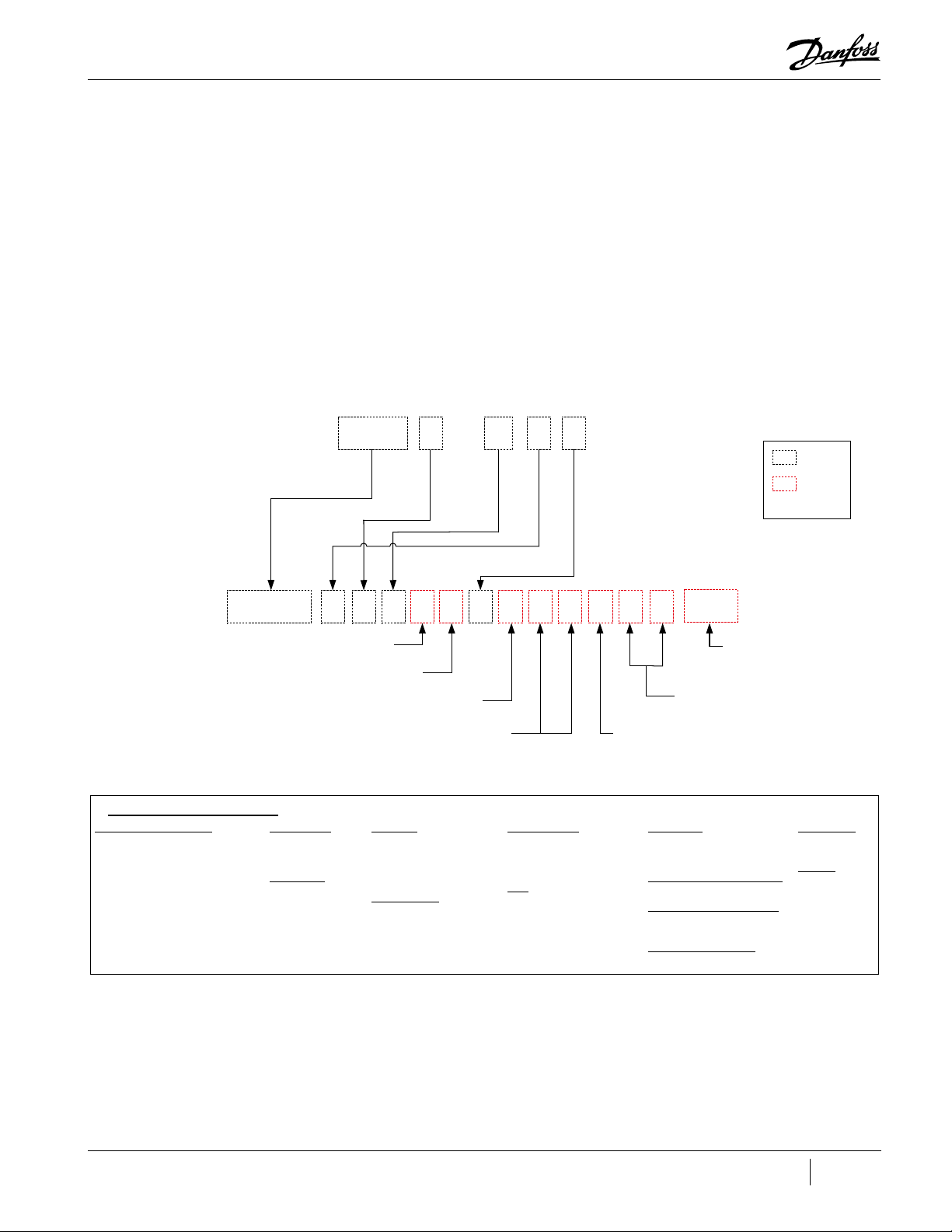
Chapter 1.0 Introduction
1.1 Application
Figure 1-1 Old to New Type Code
Conversion From Old Code to New Code
Product Series and Capacity
Note: The new code adds an “S” for
standard or “H” for High Lift
This section provides a brief introduction to the Service Manual including the Application, Purpose,
Organization, Document Conventions used, Safety Information, and the Danfoss LLC Quality Policy.
As of May 6, 2019, the product nomenclature changed. "Figure 1-1 Old to New Type Code" maps the
old structure of the Type code to the new structure. Additionally, the “Series” indicators not have an
additional character in order to differentiate the standard compressors from high-lift compressors.
Unless the compressor is a high-lift design, an “S” will be added (e.g., TTS350). A high lift compressor
will have an “H” in the Series designation (e.g., TTH375). Throughout this manual, it shall be assumed
that if a series designation contains neither an "S" or "H" (e.g., TT350) that it is not a high-lift design.
Refer to "Figure 1-2 New Type Code" on page 16 for a complete description in the new design.
**
TT300‐E‐1‐ST‐G‐O‐CE
Existing
New
Voltage Code
Application
Note: “T” is dropped
Major Revision
Build
Note: This would change
from an “O” to a “0”
Removed*
TTS300GES1S010X0XXS123
Type Code Definition
Product Series and Capacity
TTS300: TT Series 300 Aero Config
TTS350: TT Series 350 Aero Config
TTS400: TT Series 400 Aero Config
TTS500: TT Series 500 Aero Config
TTS700: TT Series 700 Aero Config
TGS230: TG Series 230 Aero Config
TGS310: TG Series 310 Aero Config
TGS390: TG Series 390 Aero Config
TGS520: TG Series 520 Aero Config
TTH375: TT High Lift Series 375 Aero
Config
TGH285: TG High Lift Series 285 Aero
Config
Mains Plate Size
I/O Board Options
Major Revision
E: Major Revision E
F: Major Revision F
G: Major Revision G
Voltage Code
E: 380V/50Hz
D: 380V/60Hz
H: 400V/50Hz
J: 400V/60Hz
G: 460V/60Hz
F: 575V/60Hz
Factory Type
Customer
Specific
Application
S: Standard Application
M: Medium Temperature
Application
J: Standard Temp KHK Listed
K: Medium Temp KHK Listed
Mains Plate Size
1: Mains Plate 2.00”
2: Mains Plate 2.48”
3: Mains Plate 3.00”
4: Mains Plate 3.50”
Accessories
I/O Board Option
S: I/O Board included with 5m
cable
M: No I/O Board, 5m cable
Included
Build
0: New Compressor
C: Rebuilt Certified Compressor
Software
Options
Reserved for
Future Options
Factory Type
1: TLH Factory (CE Rated)
2: HYN Factory (CH Rated)
3: TLH Factory (NC Rated)
Customer Specific Configuration
0: Gen Covers/Plate, EN/FR/CH
Customer Engraved Nameplate
X: No CPN (Standard)
Y: CPN on Nameplate
Accessories Configuration
0: No accessories
Future Option
X: Reserved
X: Reserved
Software
S123: Software
Revision
M-SV-001-EN Rev. G
15 of 282
Page 16
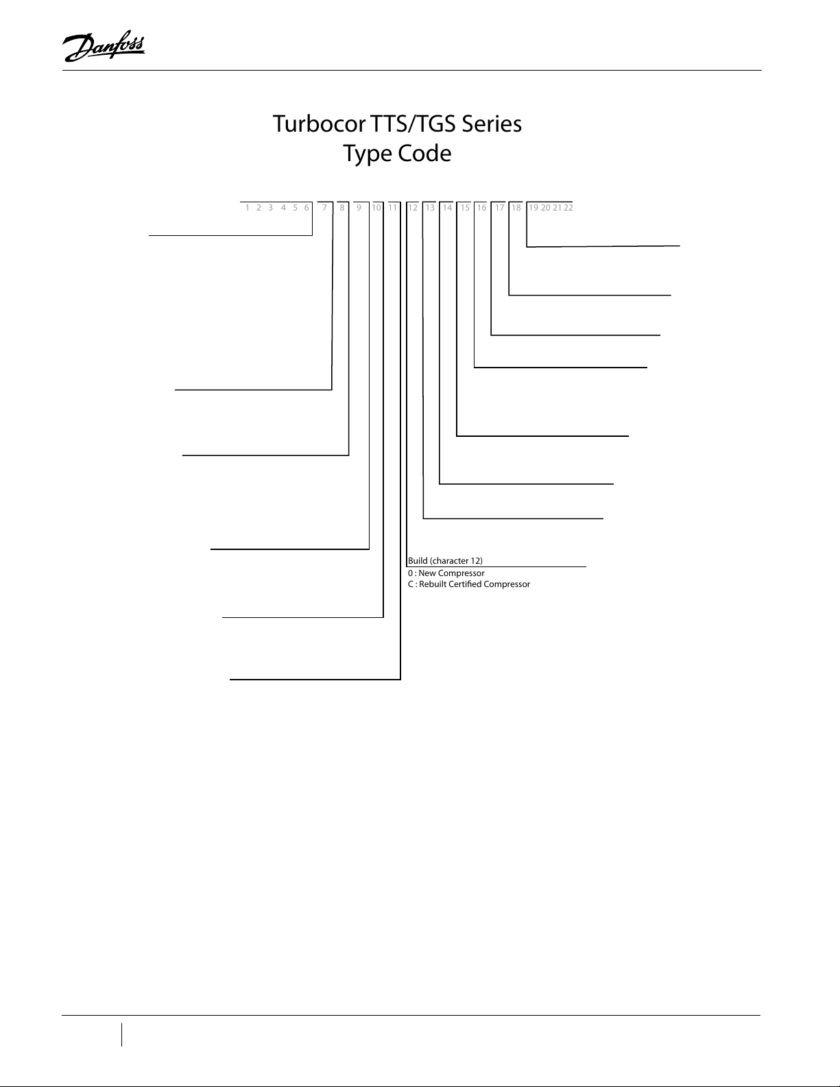
Figure 1-2 New Type Code
M : No I/O Board, 5m cable included
Build (character 12)
0 : New Compressor
C : Rebuilt Certified Compressor
1 2 3 4 5 6 7 8 9 10 11 12 13 14 15 16 17 18 19 20 21 22
Turbocor TTS/TGS Series
Type Code
TTS300 G E S 1 S 0 1 0 X 0 X X S123
Product Series and Capacity (characters 1-6)
TTS300 : TT Series 300 Aero Config
TTS350 : TT Series 350 Aero Config
TTS400 : TT Series 400 Aero Config
TTS500 : TT Series 500 Aero Config
TTS700 : TT Series 700 Aero Config
TGS280 : TG Series 280 Aero Config
TGS310 : TG Series 310 Aero Config
TGS390 : TG Series 390 Aero Config
TGS520 : TG Series 520 Aero Config
TTH375 : TT High Lift Series 375 Aero Config
TGH285 : TG High Lift Series 285 Aero Config
Major Revision (character 7)
E: Major Revision E
F : Major Revision F
G : Major Revision G
H : Major Revision H
Voltage Code (character 8)
M : Medium Temperature Application
E : 380V/50Hz
D : 380V/60Hz
H : 400V/50Hz
J : 400V/60Hz
G : 460V/60Hz
F : 575V/60Hz
Application (character 9)
S : Standard Application
J : Standard Temp KHK Listed
K : Medium Temp KHK Listed
Mains Plate Size (character 10)
1 : Mains Plate 2.00”
2 : Mains Plate 2.48”
3 : Mains Plate 3.00”
4 : Mains Plate 3.50”
I/O Board Option (character 11)
S : I/O Board included with 5m cable
1.2 Purpose
This Service Manual is intended to provide service procedures specific to the Danfoss Turbocor
compressors. It is not intended to teach basic fundamental safety, refrigeration, electrical, or fitting
skills. It is assumed persons using this manual will be appropriately certified and have detailed
knowledge, experience, and skills in respect to working with high-pressure refrigerants and medium
voltage electrical components to 1 Kilovolt (kV) high-power alternating current (AC) and direct current
(DC).
Software (character 19-22)
S123 : Software Revision
Future Option (character 18)
X : Reserved
Future Option (character 17)
X : Reserved
Accessories Configuration (character 16)
0 : No accessories
Customer Engraved Nameplate (character 15)
X : No CPN (Standard)
Y : CPN on Nameplate
Customer Specific Configuration (character 14)
0 : Gen Covers/Plate, EN/FR/CH
Factory Type (character 13)
1 : TLH Factory (CE Rated)
2 : HYN Factory (CH Rated)
3 : TLH Factory (NC Rated)
16 of 282 M-SV-001-EN Rev. G
Some potential safety situations may not be foreseen or covered in this manual. Danfoss LLC expects
personnel using this manual and working on Danfoss Turbocor compressors to be familiar with, and
carry out, all safe work practices necessary to ensure safety for personnel and equipment.
The purpose of this manual is to provide:
• A general description of the compressor design
• A functional description of the various components of the compressor
• Information regarding procedures necessary to detect the source of a problem within the
compressor
Page 17

1.3 Organization
• The procedures for disassembling and assembling various components of the compressor
• Fault and calibration interpretations
• System troubleshooting suggestions
• Maintenance tasks that should be followed
This manual gives only general procedures for servicing and does not provide part numbers of single
products or single components. If this information is required, please contact a recognized Danfoss
Turbocor original equipment manufacturer (OEM) customer.
Additionally, this manual is written for Major revision F and later compressors. When necessary,
particular revision compressors are specified, but the majority of the content remains the same,
regarless of the compressor revision. Danfoss LLC does sell various upgrade kits (e.g., Soft Start
Upgrade Kit) and and those kits may include retrofit cabling or other hardware that are not specifically
installed on production compressors. This manual only illustrates components that were installed on
production compressors. Always refer to the specific spare part kit instructions during installation.
This manual is organized in the following manner:
• Section 1: Introduction – this section describes the purpose of the manual, its organization,
conventions used in the manual, and a safety summary which describes the use of Danger,
Caution, and Notes symbols
• Section 2: Compressor Fundamentals – this section identifies the parts of the compressor
and provides fundamental knowledge of the role each component plays in the main fluid path,
motor-cooling system, and in the energy and signal flow
• Section 3: Compressor Removal and Installation – this section describes the safe practices of
removing and installing the compressor
• Section 4: Compressor Components – this section describes in depth component information,
the steps necessary to obtain measurements that verify a component is functional and the steps
necessary to replace a compressor component
• Section 5: Troubleshooting – this section describes troubleshooting using signals from the
compressor to determine the specific source of faults at the system and compressor level
• Section 6: Maintenance – this section contains a table containing a list of tasks that should be
performed on a regular basis to maintain optimal performance of the system
• Appendix A: Acronyms/Terms – this section provides definitions of terms and acronyms used
in this manual
• Appendix B: Compressor Troubleshooting Flowcharts – this section contains flowcharts to
assist you with compressor troubleshooting
• Appendix C: Compressor Test Sheet – this section contains a sheet with test points, expected
values, and the section in the manual associated with a particular test
The following conventions are used in this manual:
• Procedures – all user procedures are listed in numerical steps, unless it is a one-step procedure.
A one-step procedure is shown as a bullet.
• User Action Required (software) – if a user is required to take action in a software procedure, the
action will be shown in bold. Example; When the Login window opens, type in your name and
password.
• Monitoring Program Window Names – all window names will be in italic. Example Compressor
Controller window.
• Internal References – references to sections within this manual are encapsulated in quotes.
Example, Isolate the compressor power as described in the “Electrical Isolation of the
Compressor" section of this manual.
• External References – references to items not within this manual are underlined. Example; Refer
to the Installation and Operation Manual for installation procedures.
M-SV-001-EN Rev. G
17 of 282
Page 18

1.4 Commitment to Quality and the Environment
Danfoss Turbocor Compressors is dedicated to leading through innovation and to satisfying our
customers with the best quality, value, and on-time delivery of high-efficiency oil-free centrifugal
compressors.
We are committed to controlling our impact on the environment demonstrated through setting goals
focused on continual improvement and complying with all relevant legislation, regulation, and other
requirements to protect the environment.
1.5 Safety Summary
Safety precautions must be observed during installation, start-up, and service of the compressor due
to the presence of pressure and voltage hazards. Only qualified and trained personnel should install,
start up, and service Danfoss Turbocor compressors. Safety information is located throughout the
manual to alert service personnel of potential hazards and is identified by the headings DANGER and
CAUTION.
1.5.1 Danger Notification
A DANGER notification signifies an essential operation or maintenance procedure, practice, or
condition which, if not strictly observed, could result in injury to or death of personnel or longterm health hazards. A Danger notification is displayed in the format shown in "Figure 1-3 Danger
Notification Example".
Figure 1-3 Danger Notification Example
• • • DANGER • • •
1.5.2 Caution Notification
A CAUTION notification signifies an essential operation or maintenance procedure, practice, or
condition which, if not strictly observed, could result in damage to or destruction of equipment
or potential problems in the outcome of the procedure being performed. A Caution notification is
displayed in the format shown in "Figure 1-4 Caution Notification Example".
Figure 1-4 Caution Notification Example
1.5.3 Note
A NOTE provides additional information such as a tip, comment, or other useful, but not imperative
information. A Note is displayed in the format shown in "Figure 1-5 Note Example".
Figure 1-5 Note Example
1.6 Precautions
Consideration for personal safety and equipment safety is very important. This chapter contains
various sections that cover safety precautions and methods that must be followed when servicing the
compressor. Prior to servicing the compressor, carefully read this chapter to ensure familiarity of both
personal and equipment safety.
1.7 Refrigerant Type
1.7.1 R134a/513A
TTS and TTH series compressors are totally oil-free and optimized for use with refrigerants R134a. The
TTS and TTH are also compatible with R513A.
• • • CAUTION • • •
NOTE
18 of 282 M-SV-001-EN Rev. G
Page 19

1.7.2 R1234ze
TGS and TGH series compressors are totally oil-free and optimized for use with refrigerant R1234ze
only.
ASHRAE standard 34 has classified this refrigerant as “R1234ze(E) with safety classification of A2L.”
ASHRAE Standard 34, 2010 Addendum 1 contains the change to the standard.
1.7.3 R515B
TGS490 compressors can be used with refrigerant R515B which has an ASHRAE Standard 34 safety
classification of A1.
Table 1-2 Refrigerant Used with Danfoss Turbocor
Compressor Refrigerant
TTS Series R134a/R513A
TGS Series R1234ze, R515B (TGS490 only)
TTH Series R134a/R513A
TGH Series R1234ze
Do not use recycled refrigerant as it may contain oil, which can affect system reliability. The refrigerant should be pure and stored
in virgin containers.
1.8 Electrical Isolation
Before servicing the Compressor, isolate the compressor power by completing the following steps:
NOTE
• • • DANGER • • •
• This equipment contains hazardous voltages that can cause serious injury or death. Only
qualified and trained personnel should work on Danfoss LLC equipment.
• Always wear appropriately-rated safety equipment when working around equipment and/or components energized with
high voltage.
• Removing the Mains Input Cover will expose the technician to a high voltage hazard of up to 632 VAC. Ensure the Mains
Input power is turned off and locked out before removing the Mains Input Cover.
1. Turn off the Mains Input power to the compressor.
2. Lock Out/Tag Out (LOTO) the mains disconnect to ensure no accidental or unauthorized re-
application of the Mains Input power can occur.
NOTE
The Mains Input fast-acting fuses are installed in the power panel for all compressor models except the TT300/TG230.
3. Remove the Mains Cover only. Refer to "4.2.1 Mains Input Cover" on page 56.
4. Using an appropriately-rated voltage meter, confirm the absence of AC voltage.
• • • DANGER • • •
Do not touch any components when removing the Mains Input Cover.
5. If AC voltage is not present, reinstall the Mains Input cover and wait at least 20 minutes before
removing either the Mains Input or Top Side Cover. If AC voltage still exists, go back to Step 2 to
determine why the compressor voltage is not isolated.
6. Remove the Top Cover, taking particular care not to touch ANY components underneath. Refer
to "4.2.2 Top Cover" on page 57.
7. Using an appropriately-rated voltage meter, check the DC Bus Bars for DC voltage level. If the
M-SV-001-EN Rev. G
19 of 282
Page 20
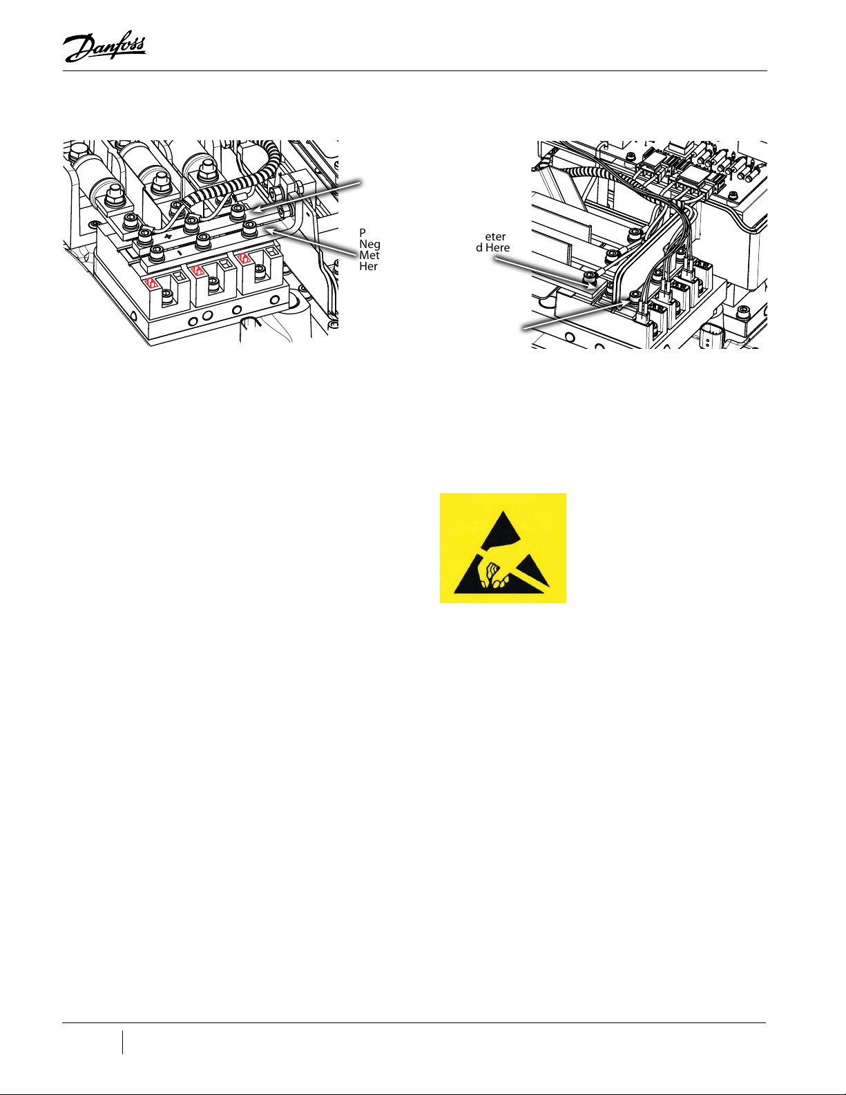
Figure 1-6 DC Bus Voltage Test Points
voltage is above 5 volts direct current (VDC), wait five (5) minutes and recheck until voltage is
below 5 VDC. Refer to "Figure 1-6 DC Bus Voltage Test Points".
Place Positive
(+) Meter
Lead Here
TTS300 Revision G Shown
1.9 Handling Static Sensitive Devices
Figure 1-7 ESD Susceptible Caution Label
Place
Negative (-)
Meter Lead
Here
Place Positive
(+) Meter
Lead Here
Place
Negative (-)
Meter Lead
Here
TTS350 Revision H Shown
Active electronic components are susceptible to damage when exposed to static electrical charges.
Damage to such components may lead to outright failure or reduction in service life. Since the
presence of static charges is not always evident, it is essential that service personnel follow static
control procedures at all times when handling sensitive electronic components.
This section outlines static control precautions that must be followed when providing service support
in the field. Service support personnel should create a safe, static-free environment.
Service personnel must use a commercially available service kit for handling static-sensitive devices.
The kit typically includes:
• Ground cord assembly
• Alligator clip
• Grounding wrist strap
• Wrist strap tester
If a safe, static control environment cannot be created for a specific reason, the operator will ensure
that electrostatic discharge (ESD) items and personnel are at the same electrical potential as the
equipment.
The electronic modules should only be removed from the ESD protective bag at the last moment, just
before installation when the operator is ready to do the replacement.
20 of 282 M-SV-001-EN Rev. G
Page 21
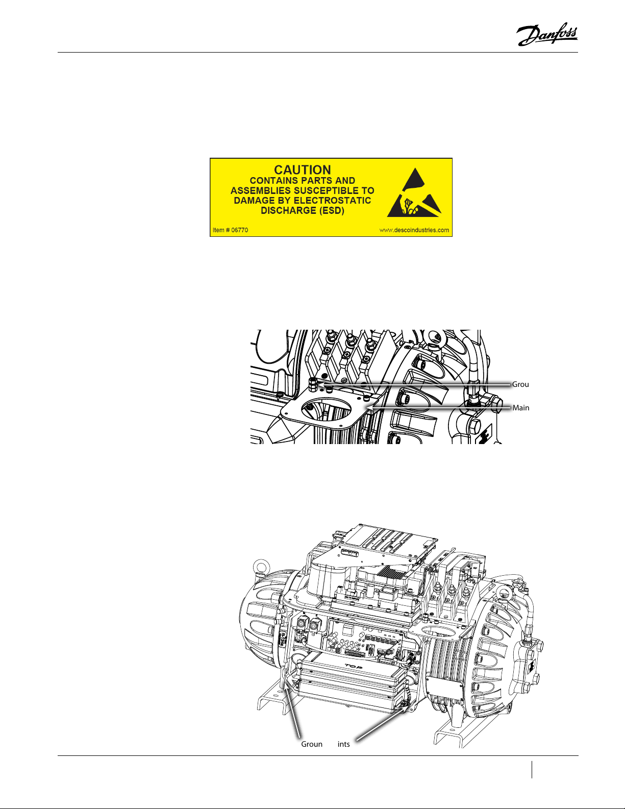
The operator should avoid touching any components or connectors on the module and should hold
the module by its edge or enclosure, as applicable.
1.9.1 ESD Protection/Grounding
All parts that are susceptible to damage by ESD will be marked using the following label. Refer to
"Figure 1-8 ESD Label". Please follow the instructions below to ensure safety and to protect the parts
from ESD damage.
Figure 1-8 ESD Label
1. Isolate the compressor power as described in "1.8 Electrical Isolation" on page 19.
2. Remove the Mains Cover. Refer to "4.2.1 Mains Input Cover" on page 56.
3. Clip the ESD strap ground clip to the compressor ground post. Refer to "Figure 1-9 Mains Plate
Figure 1-9 Mains Plate and Ground Post
and Ground Post".
4. If you need to remove the Soft Start, clip the ESD strap ground clip to the mains plate. Refer to
"Figure 1-9 Mains Plate and Ground Post".
5. If you only need to remove the Service Side Cover, clip the ESD strap ground clip to the cover
screw hole that is part of the compressor housing. Refer to "Figure 1-10 Compressor Grounding
Points".
Figure 1-10 Compressor Grounding Points
Ground Post
Mains Plate
Ground Points
M-SV-001-EN Rev. G
21 of 282
Page 22
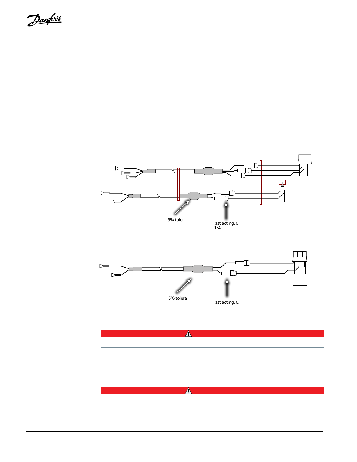
1.10 DC Bus Test Harness Installation and Removal
A DC bus test harness must be used when testing the voltages of the compressor’s power electronics.
The DC bus test harness is not designed to be left in the compressor during normal operation. When
checks are complete, disconnect and remove the test harness. There are two (2) different Soft Start
versions referenced within these instructions. The steps below are organized based on which Soft
Start is installed on the compressor. To identify the installed Soft Start, refer to "4.15 Soft Start" on
page 107.
All versions of the DC Bus Test Harness have male/female plugs to allow piggyback connection to the
required voltage measurement points on the Soft-Start. Refer to "Figure 1-11 DC Bus Test Harness
Diagram (Closed-Top Soft Start)" for an example of the harness. Voltage measurements are made
via shrouded multimeter jacks on the opposite end of the cables. Cable and personal protection are
provided by inline fast-acting fuses (1/4 x 1 1/4, 62 milliamp 250V) and current-limiting 100kΩ 3W
resistors.
Figure 1-11 DC Bus Test Harness Diagram (Closed-Top Soft Start)
Resistor, 100K, 3W, 5% tolerance
(5 places)
Fuse, Fast acting, 0.062A,
1/4x1 1/4
(5 places)
Figure 1-12 DC Bus Test Harness Diagram (Open-Top Soft Start)
Resistor, 100K, 3W, 5% tolerance
(2 places)
Fuse, Fast acting, 0.062A,
1/4x1 1/4
(2 places)
• • • CAUTION • • •
Before using the DC bus test harness, integrity of the fuses/resistors in the harness and cable must be checked.
1.10.1 General Verification and Installation of the DC Bus Test Harness
1. Isolate the compressor power as described in "1.8 Electrical Isolation" on page 19.
1 2 3
1 2 3
22 of 282 M-SV-001-EN Rev. G
• • • CAUTION • • •
Use your ESD wrist strap before touching the Soft Start Board or any electronic components.
2. Use an ESD strap and attach it the compressor housing while installing the Test Harness.
3. Remove the Service Side Cover. Refer to "4.2.3 Service Side Cover" on page 58.
Page 23
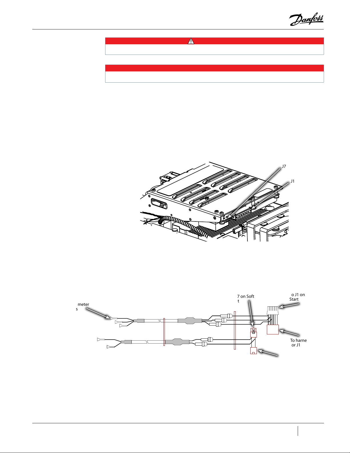
Use your ESD wrist strap before touching the Soft Start Board or any electronic components.
This would be a good time to perform a visual inspection of the top-side electronics to determine if there is any visual damage
present. Also at this time, it is suggested to verify the integrity of the fuses if you have a Closed-Top Soft Start.
4. Confirm the integrity of the fuses and resistors in the DC bus test harness by using a
multimeter set to resistance. Check each cable individually. Refer to "Figure 1-11 DC Bus Test
Harness Diagram (Closed-Top Soft Start)" and "Figure 1-12 DC Bus Test Harness Diagram (OpenTop Soft Start)"for harness fuse and resistor locations. The reading for the resistor should be
approximately 100kΩ and the reading for the fuse should be 29Ω.
5. Continue to the appropriate section below based on the particular Soft Start.
1.10.2 DC Bus Test Harness Installation for Closed-Top Soft Start
1. Disconnect the J1 and J7 connectors on the Soft Start Board. Refer to "Figure 1-13 Soft Start
(Closed Top)".
Figure 1-13 Soft Start (Closed Top)
• • • CAUTION • • •
NOTE
J7
J1
2. Connect the two (2) plugs of the compressor cable harness into the corresponding sockets of
the DC bus test harness. Refer to "Figure 1-14 Connect DC Bus Test Harness (Closed-Top Soft
Start)" for this and the following step.
Figure 1-14 Connect DC Bus Test Harness (Closed-Top Soft Start)
Multimeter
Jacks
To J7 on Soft
Start
To J1 on Soft
Start
To harness
for J1
To harness
for J7
M-SV-001-EN Rev. G
23 of 282
Page 24
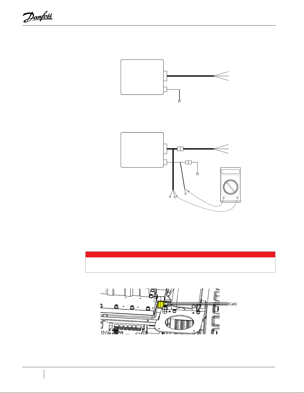
Figure 1-15 DC Bus Test Harness Connection Diagram (Closed-Top Soft Start)
ORIGINAL CONNECTIONS
Soft Start
(Top Side)
J1
J7
CONNECTIONS WITH DC BUS TEST HARNESS
Soft Start
(Top Side)
J1
Harness to DC Bus and AC Line
Harness to DC-DC Converter
Harness to DC Bus and AC Line
Figure 1-16 Cable Passage
J7
Harness to DC-DC Converter
00.0
Volt
Meter
3. Connect the two (2) plugs of the DC bus test harness into the Soft Start. Refer to "Figure 1-13
Soft Start (Closed Top)".
4. Route the cables through the cable passage on either side of the DC-DC Converter, down into
the service side. Refer to "Figure 1-16 Cable Passage" on page 24.
NOTE
• For clarity purposes, several components have been removed from "Figure 1-16 Cable Passage"
• If the main housing has two cable passages, either passage can be used
Cable Passage
24 of 282 M-SV-001-EN Rev. G
5. Carefully adjust the connectors and harness so that the Top Cover can be reinstalled.
6. Reinstall the Top Cover and Mains Input Cover. Refer to "4.2 Compressor Covers" on page 56.
7. Remove ESD strap from the compressor and yourself.
Page 25
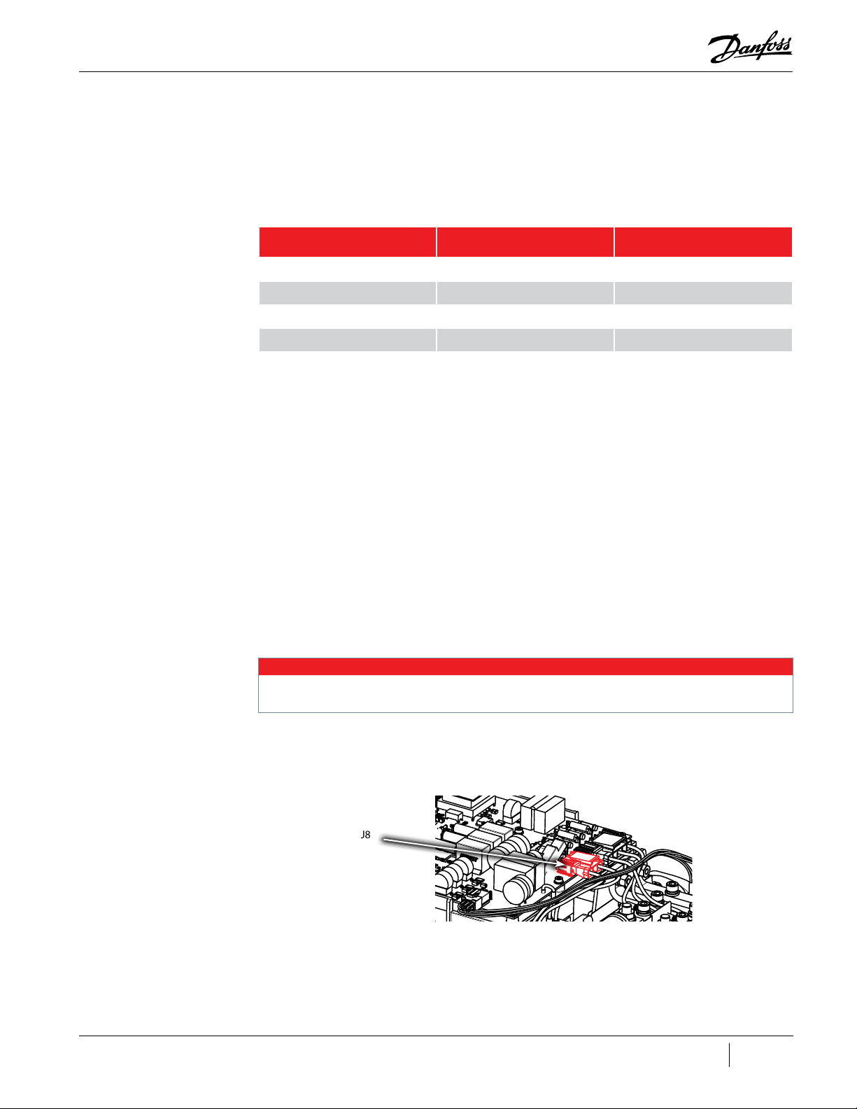
Table 1-3 Expected DC Bus Voltage
Compressor Nameplate AC
Voltage
575 VAC 518-632 VAC 700-853 VDC
460 VAC 414-506 VAC 559-683 VDC
400 VAC 360-440 VAC 486-594 VDC
380 VAC 342-418 VAC 462-564 VDC
8. Reapply AC power to the Compressor.
9. Using an appropriately-rated voltmeter with the 1000VDC range selected, insert the positive
voltmeter lead into the DC (+F) test harness lead, and the negative voltmeter lead into the DC
(-) test harness lead. If the voltage corresponds to "Table 1-3 Expected DC Bus Voltage", the DC
bus voltage is correct and HV DC (F1) fuse on the Soft Start is intact. This would imply that the
Soft Start and Silicon-Controlled Recifiers (SCRs) are functioning correctly; proceed to Step 12.
If voltage reads 0, go to Step 10.
Acceptable AC Voltage Range Expected DC Bus Voltage Range
10. Leaving the DC(-) test lead in place, relocate the positive (+) test lead to DC(+). If DC voltage is
consistent with "Table 1-3 Expected DC Bus Voltage", this would imply that the Soft Start and
SCRs are working correctly, but the HV DC fuse (F1) on the Soft Start is an open circuit, refer to
"4.25 High Voltage DC-DC Converter" on page 201 to verify the DC-DC Converter.
11. If the DC voltage is not present or is not consistent with "Table 1-3 Expected DC Bus Voltage",
the incoming AC voltage should be verified to be between the acceptable AC Voltage Range
listed in "Table 1-3 Expected DC Bus Voltage". Additionally the F2, F3, F4, F5, and F6 fuses
need to be verified as well as the SCR Diodes and SCR Gates. Refer to "4.19 Silicone-Controlled
Rectifier" on page 133 for testing details.
12. Reset multimeter scaling to read 15VAC and connect to the 15VAC leads of the DC Bus Test
Harness. If the reading is zero, isolate the three-phase supply in accordance with "1.8 Electrical
Isolation" on page 19. When access is safe, remove the four (4) fasteners that hold the Soft
Start in position, and check fuses F2, F3, F4, F5, & F6 for continuity. If any fuse is found to be an
open circuit, replace it and return to Step 6.
13. If the 15VAC is not present, replace the Soft Start (refer to "4.15.3 Soft Start Removal and
Installation" on page 112). If the 15VAC is correct, proceed to the next step.
14. When finished, remove the DC Bus Test Harness. Refer to Section 5 – Removal of the DC Bus
Test Harness.
The DC bus test harness is not designed to be left in the compressor during normal operation. When checks are complete, disconnect and remove the test harness.
1.10.2.1 DC Bus Test Harness Installation for Open-Top Soft Starts
1. Disconnect the J8 connector from the Soft Start. Refer to "Figure 1-17 J8 Soft Start Connection
(Open Top)".
Figure 1-17 J8 Soft Start Connection (Open Top)
J8
2. Connect the plug of the compressor cable harness into the corresponding socket of the DC
bus test harness. Refer to "Figure 1-18 Connect DC Bus Test Harness (Open-Top Soft Start)" and
"Figure 1-19 DC Bus Test Harness Connection Diagram (Open-Top Soft Start)" for this and the
following step.
3. Connect the plug of the DC bus test harness into the Soft Start.
• • • DANGER • • •
M-SV-001-EN Rev. G
25 of 282
Page 26

Figure 1-18 Connect DC Bus Test Harness (Open-Top Soft Start)
Multimeter
jacks
Figure 1-19 DC Bus Test Harness Connection Diagram (Open-Top Soft Start)
ORIGINAL CONNECTIONS
Soft Start
(Top Side)
CONNECTIONS WITH DC BUS TEST HARNESS
Soft Start
(Top Side)
Harness to DC Link
J8
Harness to DC Link
J8
To J8 on Soft
Start
1 2 3
1 2 3
To harness
for J8
00.0
Volt
Meter
4. Route the cables through the cable passage beside the DC-DC Converter, down into the
service side. Refer to "Figure 1-16 Cable Passage" on page 24.
NOTE
When checks are complete, disconnect and remove the test harness. If the main housing has two cable passages, wither passage
can be used.
5. Reinstall the Top Cover and Mains Input Cover. Refer to "4.2 Compressor Covers" on page 56.
6. Reapply AC power to the Compressor.
7. Insert the positive voltmeter lead into the DC (+) test harness lead, and the negative voltmeter
lead into the DC (-) test harness lead. Refer to "Table 1-3 Expected DC Bus Voltage" on page
25 for the expected DC bus voltage. If the DC bus voltage is not present, or if it is outside the
“Expected DC Bus Voltage” range shown in "Table 1-3 Expected DC Bus Voltage" on page 25,
verify proper incoming AC input, verify SCR Gates, and verify SCR Diodes. If incoming AC power
is correct, and the SCRs pass the diode and gate tests, replace the Soft Start.
26 of 282 M-SV-001-EN Rev. G
NOTE
There are no replaceable fuses present in the Open-Top Soft Start.
Page 27

8. When finished, remove the DC Bus Test Harness. Refer to "1.10.3 General DC Bus Test Harness
Removal".
1.10.3 General DC Bus Test Harness Removal
1. Isolate the compressor power as described in "1.8 Electrical Isolation" on page 19.
Use your ESD wrist strap before touching the Soft Start Board or any electronic components.
2. Use an ESD strap and attach it the compressor housing while installing the Test Harness.
3. Continue to the appropriate section below based on the particular Soft Start.
1.10.4 DC Bus Test Harness Removal for Closed-Top Soft Starts
1. Remove the DC bus test harness from the cable passage.
2. Disconnect the two (2) plugs of the DC Bus Test Harness from the Soft Start.
3. Disconnect the two (2) plugs of the compressor cable harness from the corresponding sockets
of the DC Bus Test Harness.
4. Reconnect the J1 and J7 connectors into the Soft Start.
5. Remove ESD strap from the compressor and yourself.
6. Install all covers on the compressor. Refer to "4.2 Compressor Covers" on page 56.
7. Return the compressor to normal operation.
• • • CAUTION • • •
1.10.5 DC Bus Test Harness Removal for Open-Top Soft Starts
1. Remove the DC Bus Test Harness from the cable passage.
2. Disconnect the plug of the DC Bus Test Harness from the Soft Start.
3. Disconnect the plug of the compressor cable harness from the socket of the DC Bus Test
Harness.
4. Reconnect the J8 connector into the Soft Start.
5. Remove ESD strap from the compressor and yourself.
6. Install all covers on the compressor. Refer to "4.2 Compressor Covers" on page 56.
7. Return the compressor to normal operation.
8. Disconnect the two (2) plugs of the compressor cable harness from the corresponding sockets
of the DC bus test harness.
9. Reconnect the J1 and J7 connectors onto the Soft Start.
10. Install top covers on compressor. Refer to "4.2 Compressor Covers" on page 56.
1.11 Compressor Fasteners
Only replace fasteners with exact replacements. Failure to do so could lead to fastener corrosion and/or failure.
1.12 General O-ring Handling
Various O-rings are utilized throughout the TT and TG compressors to contain the refrigerant. Prior
to the removal of any component utilizing an O-ring, the refrigerant must be properly recovered
per industry-standard procedures. Upon O-ring replacement, a leak test should be performed. The
following O-ring-specific steps are required when replacing any compressor O-ring:
1. Remove each O-ring to be installed from its package and inspect for defects such as blemishes,
abrasions, cuts, or punctures.
2. Slight stretching of the O-ring when it is rolled inside out will help to reveal some defects not
otherwise visible.
• • • CAUTION • • •
M-SV-001-EN Rev. G
27 of 282
Page 28

3. After inspection and prior to installation, lubricate the O-ring with a light coat of Super-O-Lube.
4. Avoid rolling or twisting the O-ring when maneuvering it into place.
5. Keep the position of the O-ring mold line constant.
NOTE
It is strongly suggested that anytime an O-ring is removed, that a new O-ring is used in its place.
28 of 282 M-SV-001-EN Rev. G
Page 29

Chapter 2: Compressor Fundamentals
2.1 Main Fluid Path .................................................................................................................................................................................. 31
2.2 Motor and Power Electronics Cooling .............................................................................................................................................31
2.3 Capacity Control ................................................................................................................................................................................ 34
2.4 Compressor Energy and Signal Flow ...............................................................................................................................................34
M-SV-001-EN Rev. G
29 of 282
Page 30

THIS PAGE INTENTIONALLY LEFT BLANK
30 of 282 M-SV-001-EN Rev. G
Page 31

Chapter 2.0 Compressor Fundamentals
Compressor operation begins with a demand signal applied to the compressor. The startup sequence
is configurable in the startup settings. See the OEM Programming Manual for further details.
2.1 Main Fluid Path
The compressor is a two-stage centrifugal type compressor utilizing variable speed as the principle
means of capacity control with inlet guide vanes (IGVs) assisting when required. Refrigerant enters
the first stage suction side of the compressor as a low-pressure, low-temperature, superheated
vapor. It then passes through variable IGVs that assist compressor control at part-load conditions.
Both impellers are mounted on a common shaft. Vapor passes through the first stage impeller where
velocity energy is added to the refrigerant. This is converted to an intermediate pressure in the first
stage volute. Vapor then enters the second stage impeller through a diffuser. In the second stage,
impeller velocity energy is again added to the refrigerant and converted to the final discharge pressure
in the discharge diffuser and volute. From the second stage impeller, refrigerant passes as a high
pressure, superheated vapor to the system discharge line.
Figure 2-1 Compressor Fluid Paths
4
3
5
6
3
5
6
1 1
Table 2-1 Compressor Fluid Paths
2
10
8
No. Component No. Component
1 Low Pressure/Low Temperature Gas 6 High-Pressure/High Temperature Gas
2 Inlet Guide Vanes (IGVs) 7 Second-Stage Impeller
3 First-Stage Impeller 8 Vaned Diffuser
4 Volute Assembly 9 Vaneless Diffuser
5 Discharge Port 10 De-Swirl Vanes
2
7
10
9
7
2.2 Motor and Power Electronics Cooling
Liquid refrigerant, having at least 2⁰C (Kelvin)/ 3.6°F (Rankine) sub-cooling at connection point, must
be piped to the compressor cooling inlet connection. This connection is a 1/2 inch O-ring face seal
(ORFS) connection with a built-in strainer. Refer to "Figure 2-2 Cooling Inlet Adapter" for an example of
the cooling inlet adapter.
M-SV-001-EN Rev. G
31 of 282
Page 32

Figure 2-2 Cooling Inlet Adapter
1/2" ORFS connection with strainer
Liquid refrigerant is internally channeled to two (2) solenoid valves. These valves have integral orifices
that act as expansion devices to cool the compressor motor, shaft (rotor) and power electronics.
TTS300 and TGS230 compressors have these solenoids arranged so that all components are cooled
in series with each other and the solenoids act as two stages of cooling capacity. The TTS350, TTS400,
TTS500, TTS700, T TH375, TGS310, TGS390, TGS490, TGS520, TTH375, and TGH285 compressors have
separate cooling paths for motor and power electronics. These cooling methods are identified as serial
or split cooling.
Serial cooling has its return point to the inlet of the first stage impeller, thus cooling all components
with refrigerant evaporating at the saturated suction temperature. In serial cooling versions, Solenoid
1 is opened if any temperature reaches its “turn on” point and Solenoid 2 is opened if any temperature
reaches a second “turn on” point value. Refer to cooling circuit diagram "Figure 2-5 Serial Cooling Path
- TTS300/TGS230" on page 34.
The split cooling has the motor/shaft cooling circuit return to the first stage impeller inlet and
the power electronics return to the second stage impeller inlet. This ensures a higher evaporating
(cooling) temperature to minimize condensation around the power electronic components. In the
split cooling version, Solenoid 1 is opened if either the cavity temperature or the motor temperature
reaches its “turn on” point and Solenoid 2 is opened if the Inverter or SCR temperature reaches its “turn
on” point. Refer to cooling circuit diagram "Figure 2-4 Split Cooling Path - (TTS/TGS (Except TTS300/
TGS230 Serial Cooling)" and "Figure 2-3 Split Cooling Path - TTH375/TGH285" on page 33.
Medium temperature (MT) version compressors require their motor cooling suction line to be vented
externally to the main suction line through an evaporator pressure regulating (EPR) valve. This valve
is required to ensure that evaporating temperatures cooling the motor and electronics do not get
too cold. The EPR valve should be adjusted to maintain a minimum evaporation temperature of 1.5°C
(35°F). Refer to the Applications and Installation Manual for further details.
Serial Cooling compressors can be identified by having only one 1/4 inch flare Schrader connection
adjacent to the main motor cooling liquid connection, while a split cooling model will have two. These
1/4 inch flare connections access the refrigerant feeds to the components being cooled and bypass
the solenoid valves. These ports may be used to inject liquid refrigerant directly to cool components
and enable compressors to operate during system charging operations. A minimum pressure ratio
of 1.5 and a full liquid seal at the compressor is required to ensure proper and correct compressor
cooling.
32 of 282 M-SV-001-EN Rev. G
Page 33

Figure 2-3 Split Cooling Path - TTH375/TGH285
High-Li� Cooling Circuit
Flow Diagram
Solenoid
E
Inverter
Motor Cavity
Temp. Sensor
Inverter Temp Sensor
Stator/Rotor
Inlet
(Liquid Refrigerant)
Solenoid
M
Impeller
st
Stage
1
Axial Bearing
Radial
Bearing
Figure 2-4 Split Cooling Path - (TTS/TGS (Except TTS300/TGS230 Serial Cooling)
Liquid
Refrigerant
Inlet
BMCC
SCR
Radial
Bearing
Impeller
nd
2
Stage
From Moto r
Winding Temp.
Sensor
BMCC
Solenoid
M
From Moto r
Cavity Tem p.
Sensor
ORIFICE
Solenoid
E
ORIFICE
From Inverter
Temp. Sensor
BMCC
Inverter
From SCR
Temp. Sensor
SCR
Motor/Rotor
cooling gas and
leakage
M-SV-001-EN Rev. G
33 of 282
Page 34

Figure 2-5 Serial Cooling Path - TTS300/TGS230
Liquid
Refrigerant
Inlet
2.3 Capacity Control
From Motor
Winding Temp.
Sensor
BMCC
Solenoid
M
From Motor
Cavity Temp.
Sensor
Solenoid
E
BMCC
ORIFICEORIFICE
From Inverter
Temp. Sensor
Inverter
From SCR
Temp. Sensor
SCR
Motor/Rot or
cooling gas and
leakage
Capacity control of the compressor is achieved primarily by speed modulation. When unloading,
the compressor’s first action is to reduce speed to slightly above the minimum (surge) speed for the
pressure ratio present at the time. Further reduction in capacity and an increase in shaft/impeller
stability can be achieved by closing the IGVs. These are variable angle vanes installed in the suction
inlet ahead of the first stage impeller. These guide vanes restrict the refrigerant from entering the
impeller inlet, as well as imparting a “pre swirl” of the refrigerant in the direction of impeller rotation to
increase energy efficiency during part load operation.
Speed modulation is achieved by the use of “Inverter” control. To accomplish this, the incoming
3-phase AC supply is converted to high voltage DC, incorporating smoothing/storage capacitors, and
then switched by the Inverter, utilizing 3-phase rectifiers, to give a simulated 3-phase AC supply of
variable voltage and frequency to the compressor motor.
2.4 Compressor Energy and Signal Flow
During normal operation, 3-phase power is required to be connected to the compressor at all
times, even if it is not running. Power is distributed through the following components to maintain
compressor operation:
• Silicon-Controlled Rectifier (SCR)
• Soft Start Board
• DC Capacitor Bus Bar Assembly
• Inverter
• Stator
• High-Voltage (HV) DC-DC Converter
• Backplane
• Bearing Motor Compressor Controller (BMCC)
• Serial Driver
34 of 282 M-SV-001-EN Rev. G
Page 35

• Bearing Pulse Width Modulation (PWM) Amplifier
• Compressor I/O Board
• IGV
• Solenoid actuators
The order of power and signal flow through the compressor components is as follows. Refer to "Figure
2-6 Compressor Energy and Signal Flow Connections":
1. A 3-phase voltage source is provided to the compressor through the voltage input terminal.
2. AC voltage enters the SCRs and DC voltage powers the DC bus.
3. The Soft Start Board limits the in-rush current at power-up by controlling the SCR gates.
4. DC bus voltage from the SCRs charges the capacitors.
5. DC bus provides DC voltage to Inverter.
6. The Inverter converts the DC bus voltage into a variable frequency, 3-phase simulated AC
voltage to the Stator.
7. The DC-DC Converter uses the DC bus voltage to provide 24VDC and 250VDC to the
Backplane.
8. The Backplane connects and supplies low DC voltage to the service side components.
M-SV-001-EN Rev. G
35 of 282
Page 36

Figure 2-6 Compressor Energy and Signal Flow Connections
+
TTS300 Shown
DC bus voltage from the SCRs
4
charges the capacitors
-
+
-
+
Soft Start limits the in-rush
3
current at power-up by
controlling the SCR gates
Soft Start AC Output Voltage to
DC-DC Converter
1
3-phase Voltage Input
Terminal
2
AC voltage enters the SCRs and
DC voltage powers the DC bus
DC bus provides
DC voltage to the
5
Inverter
Soft Start AC/DC Input
Voltage; DC Output Voltage
to DC-DC Converter
(+) (-)
DC BUS
-
+
-
+
DC-DC converts DC bus voltage
7
to provide 24 VDC and 250 VDC
to backplane
Backplane supplies low
8
DC voltage to service side
components
Inverter connection
Inverter converts DC bus
voltage into 3-phase
simulated AC voltage to the
stator
-
Inverter DC Bus connection
`
6
Ground
36 of 282 M-SV-001-EN Rev. G
Page 37

Refer to "Figure 2-7 Compressor Energy and Control Flow Block Diagram - TTS/TGS Compressors" for a
g
block diagram summary of the energy and voltage signal flow through the compressor.
NOTE
TTH/TGH Compressors are very similar to "Figure 2-7 Compressor Energy and Control Flow Block Diagram - TTS/TGS Compressors".
Figure 2-7 Compressor Energy and Control Flow Block Diagram - TTS/TGS Compressors
External Pw er Cmpnents
3-Phase
380-575VAC
50/60 Hz
EMI/EMC
Filter
T Mtr Cling Slenids
T IGV Stepper Mtr
RS-485 Cmms
t Chiller r Building
Management System
Internet
Line
Reactr
Cmpressr
Inputs
Cmpressr
Outputs
Chiller Cntrl
Cmmunicans
Surge
Suppressr
Harmnic
Filter
External Expansin Valves
+24VDC
+15VDC
0-10VDC
0-10VDC
User Interface
Interface
Diagnsc
Terminal
3-Phase
380-575VAC
50/60 Hz
+15VDC
Serial
Driver
Mdule
Cmpressr
I/O
Bard
ntrlled
Rece
0-12 VDC
S-Start
Cntrller
Bearing
Mtr
Cmpressr
Cntrller
(BMCC
+15VDC
+24VDC
Cntrl
Feedback
+5VDC
+15VDC
Cntrl
Feedback
Mtr Dri ve
460-853 VDC
460-853 VDC
460-853 VDC
15 VAC
DC Link
Capacitrs
DC/DC
Cnverter
+24VDC
+5VDC
+15VDC
-15VDC
Cntrl
Nte:
All vltage leve ls shwn have the fllwing errr tlerance:
HV
Backplane
DC (except the DC bus: ±5%
AC : ±10%
0 VDC
Cntrl
Feedback
+
(+250VDC
Cntrl
Feedback
3-Phase
Inverter
+24VDC
Gang
Signals
Sha Psin Outputs
-1.5-1.5A
Frnt
Radial
Bearing
V
Frequency
a
(0-750Hz
V
b
AC Vltage
V
c
T Statr
+
HV
Bearing PWM
Variable
+17VDC
Amplier
+5VDC
Rear
Radial
Bearing
-1.5-1.5A
(Calibran(Calibran
-1.5-1.5A
Axial
Bearin
M-SV-001-EN Rev. G
37 of 282
Page 38

THIS PAGE INTENTIONALLY LEFT BLANK
38 of 282 M-SV-001-EN Rev. G
Page 39

Chapter 3: Compressor Removal and Installation
3.1 Refrigerant Containment .................................................................................................................................................................. 41
3.2 Compressor Removal ........................................................................................................................................................................ 41
3.3 Compressor Installation....................................................................................................................................................................42
3.4 Compressor Replacement Considerations for Motor Cooling Adapter ........................................................................................43
3.5 Exterior Connection Torque Specifications ..................................................................................................................................... 45
M-SV-001-EN Rev. G
39 of 282
Page 40

THIS PAGE INTENTIONALLY LEFT BLANK
40 of 282 M-SV-001-EN Rev. G
Page 41

Chapter 3.0 Compressor Removal and Installation
3.1 Refrigerant Containment
Isolation and recovery of the refrigerant must be performed by a qualified service technician adhering to industry/ASHRAE
standards.
1. Close the suction, discharge, and economizer isolating valves as appropriate.
2. Close the motor-cooling liquid line shut-off valve.
3. Use a magnet to manually open at least one of the motor cooling solenoids.
4. Connect a refrigerant recovery system to the compressor as per industry-standard procedures
and transfer the refrigerant to an appropriate containment vessel.
3.2 Compressor Removal
1. Isolate the Compressor power as described in the "1.8 Electrical Isolation" on page 19
section of this manual.
Ensure that there is no secondary power source connected to the compressor before disconnecting the following cables:
2. Remove the power cables.
3. Remove the ground wire from the ground post.
Figure 3-1 Compressor Power Cable Removal
• • • CAUTION • • •
• • • CAUTION • • •
TTS350 Major Rev. F shown
4. Remove the Service Side Cover.
5. Disconnect the I/O cable from the Backplane I/O connector (J7) and remove the cable from the
compressor.
6. Once the transfer of refrigerant is complete, bring the compressor back to atmospheric
pressure according to industry standards using dry nitrogen.
7. Disconnect the compressor from the refrigerant system connections (suction, discharge,
economizer and motor cooling line), taking care when removing connections that there is no
residual pressure.
8. Install the Service Side Cover.
9. Install the Mains Input Cover.
10. Position the lifting hoist/crane with the 2-point spreader bar directly above the lifting points.
11. Using a properly rated chain/cable, connect the spreader bar to the compressor lifting points.
12. Confirm that all lifting points are secured in accordance with relevant safety procedures and
standards.
13. Connect an appropriate lifting device to the eyebolts provided on each side of the compressor.
14. Remove the four (4) compressor mounting fasteners and associated hardware from the base of
the compressor.
15. Lift the compressor approximately 100 mm (4”). Confirm that the compressor and spreader bar
are properly balanced between the lifting points and the lifting hoist.
M-SV-001-EN Rev. G
41 of 282
Page 42

16. Continue the removal of the compressor and lower to the desired location in order to remove
the chains/cables.
17. Using the blanking plates and bolts provided with the new compressor, seal the compressor
and charge to 15 psi with a nontoxic inert gas (e.g., nitrogen) for shipment (this will prevent
moisture and foreign material from entering the compressor).
3.3 Compressor Installation
Blanking plates should not be removed from the new compressor until you are ready to place the new compressor in operation.
New compressors are pressurized with nitrogen to 15 psi. Pressure should be relieved through the Schrader valve, located next to
the motor cooling connection, prior to removing the blanking plates. Isolation and recovery of the refrigerant must be performed
by a qualified technician. Always wear proper safety equipment when handling refrigerants.
Install new O-rings when attaching flanges to the compressor.
1. Relieve the inert gas pressure through the motor cooling exit port Schrader valve.
2. Remove the suction, discharge, and economizer (if applicable) blanking plates from the
compressor.
3. Remove the motor cooling inlet adapter cap. Refer to "3.4 Compressor Replacement
Considerations for Motor Cooling Adapter" on page 43.
4. Ensure that all connections have protective covers to prevent foreign object damage during
installation.
5. Attach the spreader bar to the two (2) lifting hooks (eye bolts) on the top of the compressor
and confirm that all lifting points are secured in accordance with relevant safety procedures
and standards.
6. Position an appropriate lifting hoist/crane and connect to the spreader bar.
7. Confirm that the compressor and spreader bar are properly balanced between the lifting
points and the lifting hoist.
8. Slowly lower the compressor until it is positioned within approximately 5 mm (¼”) of the
compressor mounts.
9. Loosely install the rubber mounts and mounting fasteners to the base of the compressor.
10. Slowly release the load from the crane so that compressor weight is supported by the
compressor mounts.
11. Tighten the suction flange fasteners to 75 Nm (55 ft.lb.).
12. Tighten the discharge flange fasteners to 32 Nm (24 ft.lb.).
13. Tighten the economizer flange fasteners (if applicable) to 32 Nm (24 ft.lb.).
14. Torque the compressor mounting base fasteners to 22 Nm (16 ft.lb.).
Figure 3-2 Compressor Mounting Fasteners
NOTE
NOTE
42 of 282 M-SV-001-EN Rev. G
Mounting Base Fastener,
M12, 22 Nm (16 ft.lb.)
(4 places)
Page 43

15. Torque the motor cooling line connection (Nut) to 11 Nm (8 ft.lb.).
16. Remove the Service Side Cover.
17. Install the I/O strain relief to the compressor housing.
18. Connect the compressor I/O cable to the Backplane I/O connector (J7).
19. Install the Service Side Cover.
• • • DANGER • • •
Ensure that electrical power is isolated from the AC mains cables before handling the cables.
20. Remove the Mains Input Cover.
21. Connect the cable gland that secures the Mains Input cable conduit to the Mains Input
bracket.
22. Install the Mains Input ground wire to the ground post and torque the top nut to 10 Nm (7
ft.lb.).
23. Attach the AC mains cables to the terminals and torque to specification.
• TTS300/TGS230 Compressors - 20 Nm (15 ft.lb.)
• All Compressors (excluding TT300/TG230) - 21 Nm (15 ft.lb.)
24. Install the Mains Input Cover. Refer to "4.2.1 Mains Input Cover" on page 56.
25. Leak test and evacuate in accordance with standard industry practices.
26. Return the compressor to normal operation.
3.4 Compressor Replacement Considerations for Motor Cooling Adapter
The housing connection seal is an ISO standard O-ring seal and the external pipework connection
is an ORFS. In addition, the line size has been standardized at 1/2 inch for all models and the fitting
includes a built-in (removable) strainer.
The current fitting consists of 1) body (including both O-rings), 2) strainer, 3) blanking disc, 4) 1/2”
braze sleeve, steel (all for connecting 1/2 inch copper tube) and 5) nut. Body to compressor housing
thread is M16 x 1.5. Refer to "Figure 3-3 Motor Cooling Fitting".
Figure 3-3 Motor Cooling Fitting
O-ring
Body
Adapter Body
Connection thread
M16x1.5
25 Nm (18 ft.lb.)
O-ring
Strainer
Nut
Inside thread 13/16 UN-2A
11 Nm (8 ft.lb.)
Blanking Disk
Braze Sleeve
Tube connection thread is 13/16-16 UN-2A. Strainer recess is Ø 9.5.
Flexible Line
1. If the connection is a flexible hose to 3/8 or 1/2 inch flare, the entire hose will require
replacement with the current style.
M-SV-001-EN Rev. G
43 of 282
Page 44

2. Isolate the compressor and recover the refrigerant according to industry standards. Refer to
"3.1 Refrigerant Containment" on page 41.
3. Source appropriate OEM specified and procured flexible line.
4. Remove the nut from the connection fitting body. Discard the blanking disc, nut, and braze
sleeve.
5. Before installation of the OEM supplied flexible line, inspect the O-ring face to ensure it is clean
and free from scratches or other damage. Lightly smear O-ring lube on the O-ring face of the
line and install using two (2) wrenches; one to hold body of fitting and one to tighten the nut.
This is done to prevent over torqueing the fitting in the compressor housing.
6.
Flexible lines are not supplied by Danfoss LLC. Selection of appropriate hose and fitting is the responsibility of OEM/installer. This
information is readily available from various sources.
NOTE
Rigid 1/2 inch copper connection
1. If the connection is 1/2 inch rigid copper, a length of 1/2 inch copper must be brazed into the
braze sleeve.
2. Isolate the compressor and recover the refrigerant according to industry standards. Refer to
"3.1 Refrigerant Containment" on page 41.
3. Remove the nut from the connection-fitting body. Discard the blanking disc. Locate the braze
sleeve and clean. Ensure removal of all oil and surface debris. Braze as per the OEM standard
process for copper/steel joint.
4. Place an appropriate length of 1/2 inch copper tube into the braze sleeve. Pretreat/flux joint
area as per the OEM standard procedure. Braze the pipe to the sleeve ensuring the nut can be
fitted after brazing or otherwise position as required. Clean flux and any excess filler from joint.
5. Clean the O-ring face of the sleeve ensuring no scratches or debris are present. Apply a light
amount of O-ring lube to the face of the sleeve and assemble to the fitting. Tighten the nut
using two (2) wrenches; one to hold body of fitting and one to tighten the nut. This is done to
prevent over torqueing the fitting in the compressor housing
Rigid 3/8 inch copper connection - TTS300/TGS230
• If the connection is 3/8 inch rigid copper, a length of 1/2 inch copper must be brazed into the
braze sleeve as described above. A transition fitting should be brazed to connect the 3/8 to 1/2
inch tubes. Follow the procedure as noted above in Rigid 1/2 Copper Connection section.
Important
• It should be noted that the inclusion of a strainer within the connection body is intended as a
last resort backup only to prevent ingress of debris that may block solenoid orifices or restrict
motor and power electronics cooling. It is not a substitute for a correctly sized full-flow filter
drier. A filter drier must be installed in all instances. If it is found that a filter drier is not installed,
and the fitting is changed due to a field replacement of the compressor, a filter drier must be
included in the line modification.
• If it is required to remove the fitting from the housing for any reason, clean the O-ring, fitting
and housing threads, and apply a small amount of O-ring lube before reassembly.
44 of 282 M-SV-001-EN Rev. G
Page 45

3.5 Exterior Connection Torque Specifications
Table 3-1 Exterior Connection Torque Specifications
Description Thread Depth (mm)Nm Ft.Lb. In.Lb.
Power Cable Nut (excluding TTS300/TGS230 compressors) - 21 15 186
Input Pressure Screws (TTS300/TGS230 compressors) - 20 15 177
Motor Cooling Body, E-housing and later - 25 18 221
Motor Cooling Compression Nut, E-housing and later - 11 8 97
Ground Post, Top Nut - 10 7 89
Ground Post, Second (Jam) Nut - 7 - 62
Ground Post, Lower Nut - 20 15 177
Suction Flange Fastener 34.5 75 55 664
Discharge Flange Fastener 20 32 24 283
Economizer Flange Fastener 20 32 24 283
Schrader Valve - 15 11 133
Base Mounting Bolt 24 22 16 195
Cover Fastener - 1.5 - 13
Compressor Mounting Fastener - 14 10 124
M-SV-001-EN Rev. G
45 of 282
Page 46

THIS PAGE INTENTIONALLY LEFT BLANK
46 of 282 M-SV-001-EN Rev. G
Page 47

Chapter 4: Compressor Components
4.1 Component Identification ................................................................................................................................................................ 51
4.2 Compressor Covers............................................................................................................................................................................ 56
4.2.1 Mains Input Cover ..................................................................................................................................................................................................................................................56
4.2.2 Top Cover...................................................................................................................................................................................................................................................................57
4.2.3 Service Side Cover..................................................................................................................................................................................................................................................58
4.2.4 Capacitor Cover ...................................................................................................................................................................................................................................................... 59
4.2.5 Compressor Cover Torque Specifications ...................................................................................................................................................................................................... 60
4.3 Cooling Adapter ................................................................................................................................................................................61
4.3.1 Cooling Adapter Removal and Installation ................................................................................................................................................................................................... 62
4.3.2 Cooling Adapter Torque Specifications ..........................................................................................................................................................................................................62
4.4 Compressor Interface Module .......................................................................................................................................................... 63
4.4.1 Compressor Interface Module Connection Descriptions ........................................................................................................................................................................ 63
4.4.2 Compressor Interface Module Verification ...................................................................................................................................................................................................65
4.4.3 Compressor Interface Module Removal & Installation ............................................................................................................................................................................. 66
4.5 Compressor Interface Cable ............................................................................................................................................................. 66
4.5.1 Compressor Interface Cable Verification .......................................................................................................................................................................................................67
4.5.2 Compressor Interface Cable Removal and Installation ............................................................................................................................................................................67
4.6 Compressor Controller Cable Harness ............................................................................................................................................. 67
4.6.1 Compressor Controller Cable Connections .................................................................................................................................................................................................. 68
4.6.2 Compressor Controller Cable Harness Removal and Installation ........................................................................................................................................................ 68
4.6.3 Compressor Controller Cable Harness Torque Specifications ................................................................................................................................................................ 72
4.7 Solenoids and Coils ........................................................................................................................................................................... 72
4.7.1 Solenoid and Coil Connections ......................................................................................................................................................................................................................... 72
4.7.2 Solenoid Coil Harness ........................................................................................................................................................................................................................................... 73
4.7.3 Solenoid Verification .............................................................................................................................................................................................................................................73
4.7.4 Solenoid and Coil Removal and Installation................................................................................................................................................................................................. 75
4.8 Interstage Pipe - TTH/TGH ................................................................................................................................................................77
4.8.1 Interstage Pipe Removal and Installation ......................................................................................................................................................................................................77
4.8.2 Interstage Pipe Torque Specifications.............................................................................................................................................................................................................78
4.9 Compressor Housing End Cap .......................................................................................................................................................... 78
4.9.1 Compressor Housing End Cap Removal and Installation ........................................................................................................................................................................ 79
4.10 IGV .................................................................................................................................................................................................... 80
4.10.1 IGV Connections ................................................................................................................................................................................................................................................... 80
4.10.2 IGV Verification .....................................................................................................................................................................................................................................................81
4.10.3 IGV Housing Removal and Installation ........................................................................................................................................................................................................ 83
4.10.4 IGV Torque Specifications .................................................................................................................................................................................................................................92
4.11 Mains Plate Bracket ......................................................................................................................................................................... 93
4.11.1 Mains Plate Bracket Removal and Installation .......................................................................................................................................................................................... 93
4.12 3-Phase Main Voltage Input Terminal Block ................................................................................................................................. 95
4.12.1 3-Phase Main Voltage Input Terminal Block Verification .......................................................................................................................................................................96
4.12.2 3-Phase Main Voltage Input Terminal Block Removal and Installation ............................................................................................................................................ 98
4.13 Input Mains Bus Bars (Except TTS300/TGS230) .......................................................................................................................... 103
4.14 Terminal Block Fuse Replacement ...............................................................................................................................................105
4.14.1 Verification of Terminal Block Fuse ..............................................................................................................................................................................................................105
4.14.2 Terminal Block Fuse Removal and Installation ........................................................................................................................................................................................106
4.15 Soft Start ........................................................................................................................................................................................ 107
4.15.1 Soft Start Connections .....................................................................................................................................................................................................................................108
4.15.2 Soft Start Verification ........................................................................................................................................................................................................................................109
4.15.3 Soft Start Removal and Installation.............................................................................................................................................................................................................112
4.15.4 Soft Start Removal (Closed-Top) ...................................................................................................................................................................................................................112
4.15.5 Soft Start Removal (Open-Top) .....................................................................................................................................................................................................................114
4.15.6 Soft Start Installation (Closed-Top) ..............................................................................................................................................................................................................116
4.15.7 Soft Start Installation (Open-Top) ................................................................................................................................................................................................................117
4.15.8 Soft Start Fan Removal and Installation ....................................................................................................................................................................................................117
4.15.9 Soft Start Fan Removal.....................................................................................................................................................................................................................................117
4.15.10 Soft Start Fan Installation .............................................................................................................................................................................................................................118
M-SV-001-EN Rev. G
47 of 282
Page 48

4.16 SCR DC Bus Bar - TTS300/TGS230 ................................................................................................................................................119
4.16.1 SCR DC Bus Bar Removal and Installation .................................................................................................................................................................................................120
4.17 Soft Start SCR Gate Cable ............................................................................................................................................................. 121
4.17.1 Soft Start SCR Gate Cable Connections .....................................................................................................................................................................................................121
4.17.2 Soft Start SCR Gate Cable Removal and Installation .............................................................................................................................................................................121
4.18 Soft Start AC/DC Harness .............................................................................................................................................................. 124
4.18.1 Soft Start AC/DC Harness Connections .....................................................................................................................................................................................................125
4.18.2 Soft Start AC/DC Harness Removal and Installation .............................................................................................................................................................................127
4.19 Silicone-Controlled Rectifier ....................................................................................................................................................... 133
4.19.1 SCR Connections ................................................................................................................................................................................................................................................134
4.19.2 SCR Verification ...................................................................................................................................................................................................................................................135
4.19.3 SCR Removal and Installation........................................................................................................................................................................................................................141
4.20 SCR Cooling Manifold ...................................................................................................................................................................150
4.20.1 SCR Cooling Manifold General Removal ...................................................................................................................................................................................................150
4.20.2 SCR Cooling Manifold Removal - TTS300/TGS230 .................................................................................................................................................................................150
4.20.3 SCR Cooling Manifold Removal - TTS/TGS/TTH/TGH (Except TTS300/TGS230) ..........................................................................................................................151
4.20.4 SCR Cooling Manifold Installation - TTS300/TGS230 ............................................................................................................................................................................152
4.20.5 SCR Cooling Manifold Installation - TTS/TGS/TTH/TGH (Except TTS300/TGS230) .....................................................................................................................153
4.20.6 SCR Cooling Manifold General Installation ..............................................................................................................................................................................................154
4.20.7 SCR Cooling Manifold Torque Specifications. ..........................................................................................................................................................................................155
4.21 Snubber Capacitors .......................................................................................................................................................................156
4.22 DC Capacitor Bus Bar Assembly ................................................................................................................................................... 156
4.22.1 DC Capacitor DC Bus Bar Connections ......................................................................................................................................................................................................157
4.22.2 DC Bus Voltage Verification ............................................................................................................................................................................................................................158
4.22.3 DC Capacitor Bus Bar Assembly Removal and Installation .................................................................................................................................................................158
4.22.4 DC Capacitor Bus Bar Assembly General Removal ................................................................................................................................................................................158
4.22.5 DC Capacitor Bus Bar Assembly General Installation Steps ...............................................................................................................................................................163
4.22.6 DC Capacitor Bus Bar Assembly Torque Specifications .......................................................................................................................................................................164
4.23 Inverter...........................................................................................................................................................................................165
4.23.1 Inverter Connections ........................................................................................................................................................................................................................................165
4.23.2 Inverter Verification ...........................................................................................................................................................................................................................................165
4.23.3 Inverter Cable Harness .....................................................................................................................................................................................................................................166
4.23.4 Inverter Cable Harness Removal and Installation ..................................................................................................................................................................................166
4.23.5 Inverter Cable Harness Installation .............................................................................................................................................................................................................167
4.23.6 Inverter Removal and Installation................................................................................................................................................................................................................168
4.23.7 Inverter Card Replacement ............................................................................................................................................................................................................................187
4.23.8 Inverter Torque Specifications ......................................................................................................................................................................................................................190
4.24 Motor Components ....................................................................................................................................................................... 191
4.24.1 Function ................................................................................................................................................................................................................................................................191
4.24.2 Motor Protection ................................................................................................................................................................................................................................................191
4.24.3 Motor Connections ...........................................................................................................................................................................................................................................192
4.24.4 Motor Verification ..............................................................................................................................................................................................................................................192
4.24.5 Motor Assembly Removal and Installation...............................................................................................................................................................................................193
4.25 High Voltage DC-DC Converter ....................................................................................................................................................201
4.25.1 DC-DC Converter Function .............................................................................................................................................................................................................................201
4.25.2 DC-DC Converter Verification ........................................................................................................................................................................................................................201
4.25.3 DC-DC Supply Cable Harness .......................................................................................................................................................................................................................202
4.25.4 DC-DC Harness Removal and Installation .................................................................................................................................................................................................203
4.26 Backplane ...................................................................................................................................................................................... 207
4.26.1 Backplane Function ..........................................................................................................................................................................................................................................207
4.26.2 Backplane Connections and Test Points ...................................................................................................................................................................................................208
4.26.3 Backplane Removal and Installation...........................................................................................................................................................................................................211
4.27 Serial Driver ................................................................................................................................................................................... 212
4.27.1 Serial Driver Function .......................................................................................................................................................................................................................................212
4.27.2 Serial Driver Connections ...............................................................................................................................................................................................................................213
4.27.3 Serial Driver Verification ..................................................................................................................................................................................................................................213
4.27.4 Serial Driver Removal and Installation .......................................................................................................................................................................................................213
4.28 BMCC ..............................................................................................................................................................................................214
4.28.1 BMCC Connections............................................................................................................................................................................................................................................215
4.28.2 BMCC Verification ..............................................................................................................................................................................................................................................215
48 of 282 M-SV-001-EN Rev. G
Page 49

4.28.3 BMCC Battery and Verification ......................................................................................................................................................................................................................215
4.28.4 BMCC Removal and Installation ...................................................................................................................................................................................................................217
4.29 Bearing Pulse Width Modulator Amplifier .................................................................................................................................. 218
4.29.1 PWM Function .....................................................................................................................................................................................................................................................218
4.29.2 PWM Connections .............................................................................................................................................................................................................................................219
4.29.3 PWM Verification ................................................................................................................................................................................................................................................220
4.29.4 PWM Removal and Installation .....................................................................................................................................................................................................................221
4.30 Magnetic Bearings ........................................................................................................................................................................ 223
4.30.1 Magnetic Bearings Function ..........................................................................................................................................................................................................................223
4.30.2 Magnetic Bearings Connections ..................................................................................................................................................................................................................223
4.30.3 Bearing Verification ...........................................................................................................................................................................................................................................223
4.30.4 Bearing Power Feedthrough Removal and Installation .......................................................................................................................................................................226
4.31 Bearing Sensors ............................................................................................................................................................................. 228
4.31.1 Bearing Sensor Function .................................................................................................................................................................................................................................228
4.31.2 Bearing Sensor Connection ...........................................................................................................................................................................................................................228
4.31.3 Bearing Sensor Verification ............................................................................................................................................................................................................................229
4.31.4 Bearing Sensor Cable Removal and Installation .....................................................................................................................................................................................229
4.31.5 Bearing Sensor Removal and Installation .................................................................................................................................................................................................229
4.32 Cavity Temperature Sensor .......................................................................................................................................................... 231
4.32.1 Cavity Temperature Sensor Function .........................................................................................................................................................................................................231
4.32.2 Cavity Temperature Sensor Connections ..................................................................................................................................................................................................232
4.32.3 Cavity Temperature Sensor Verification .....................................................................................................................................................................................................232
4.32.4 Cavity Temperature Sensor Removal and Installation ..........................................................................................................................................................................232
4.33 Pressure/Temperature Sensor ...................................................................................................................................................... 234
4.33.1 Pressure/Temperature Sensor Function ....................................................................................................................................................................................................234
4.33.2 Pressure/Temperature Sensor Connections .............................................................................................................................................................................................234
4.33.3 Pressure/Temperature Sensor Verification ...............................................................................................................................................................................................234
4.33.4 Pressure/Temperature Sensor Removal and Installation ....................................................................................................................................................................236
M-SV-001-EN Rev. G
49 of 282
Page 50

THIS PAGE INTENTIONALLY LEFT BLANK
50 of 282 M-SV-001-EN Rev. G
Page 51

Chapter 4.0 Compressor Components
This section provides compressor component locations and functional descriptions, verification
and troubleshooting methods, cable connection identification, and steps necessary to replace a
component.
4.1 Component Identification
This section identifies the major parts of the compressor.
Figure 4-1 Compressor Components Identification (Covers On)
1
12
11
2
3
4
10
9
8
Table 4-1 Compressor Components (Covers On)
No. Component No. Component
1 Top Cover 7 Service Side Cover
2 Mains Input Cover 8 Rear Support Base
3 Lift Anchor (Front) 9 Compressor I/O Board
4 Cable Harness (Sensor) 10 Compressor I/O Board Cable
5 IGV Housing 11 End Cap
6 Front Support Base 12 Lift Anchor (Rear)
5
6
7
M-SV-001-EN Rev. G
51 of 282
Page 52

Figure 4-2 Compressor Component Identification - Service Side (Excludes TTH/TGH Compressors)
TT300 Shown
12
11
10
9
8
7
6
v
45
3
Table 4-2 Compressor Components Service Side (Excludes TTH/TGH Compressors)
13
14
1
2
No. Component No. Component
1 Suction Pressure/Temperature Sensor 8 Compressor Cooling Access Port Access
2 IGV Suction Port 9 Compressor Cooling Access Port #2
3 PWM Amplifier 10 Motor-Cooling Connection
4 BMCC 11 DC-DC Converter
5 Serial Driver 12 Soft Start
6 Backplane 13 Inverter
7 Motor-Cooling Solenoids 14 Fast-Acting Fuses (TTS300/TGS230 only)
Port #1 (NOTE: TTS300/TGS230 have only
one access port)
(not available on TTS300/TGS230
compressors) NOT SHOWN
52 of 282 M-SV-001-EN Rev. G
Page 53

Figure 4-3 Compressor Component Identification - Service Side (TTH/TGH Only)
12
11
10
9
8
7
6
5
4
13
14
Table 4-3 Compressor Components Service Side (TTH/TGH Only)
No. Component No. Component
1 PWM Amplifier 8 Suction Pressure/Temperature Sensor
2 BMCC 9 Motor-Cooling Solenoids
3 Serial Driver 10 Motor-Cooling Connection
4 Backplane 11 DC-DC Converter
5 Compressor Cooling Access Port 12 Soft Start Board
6 IGV Suction Port 13 Inverter
7 Compressor Cooling Access Port 14 AC Mains Bus Bars
23
1
M-SV-001-EN Rev. G
53 of 282
Page 54

Figure 4-4 Compressor Component Identification - Capacitor Side (Excludes TTH/TGH)
7
6
5
4
3
2
Table 4-4 Compressor Components Capacitor Side (Excludes TTH/TGH)
No. Component No. Component
1
1 Capacitors 5 Optional Pressure Regulating Port
2 IGV Position Indicator 6 IGV Motor Feedthrough
3 Economizer Port 7 Discharge Temperature/Pressure Sensor
4 Discharge Port
54 of 282 M-SV-001-EN Rev. G
Page 55
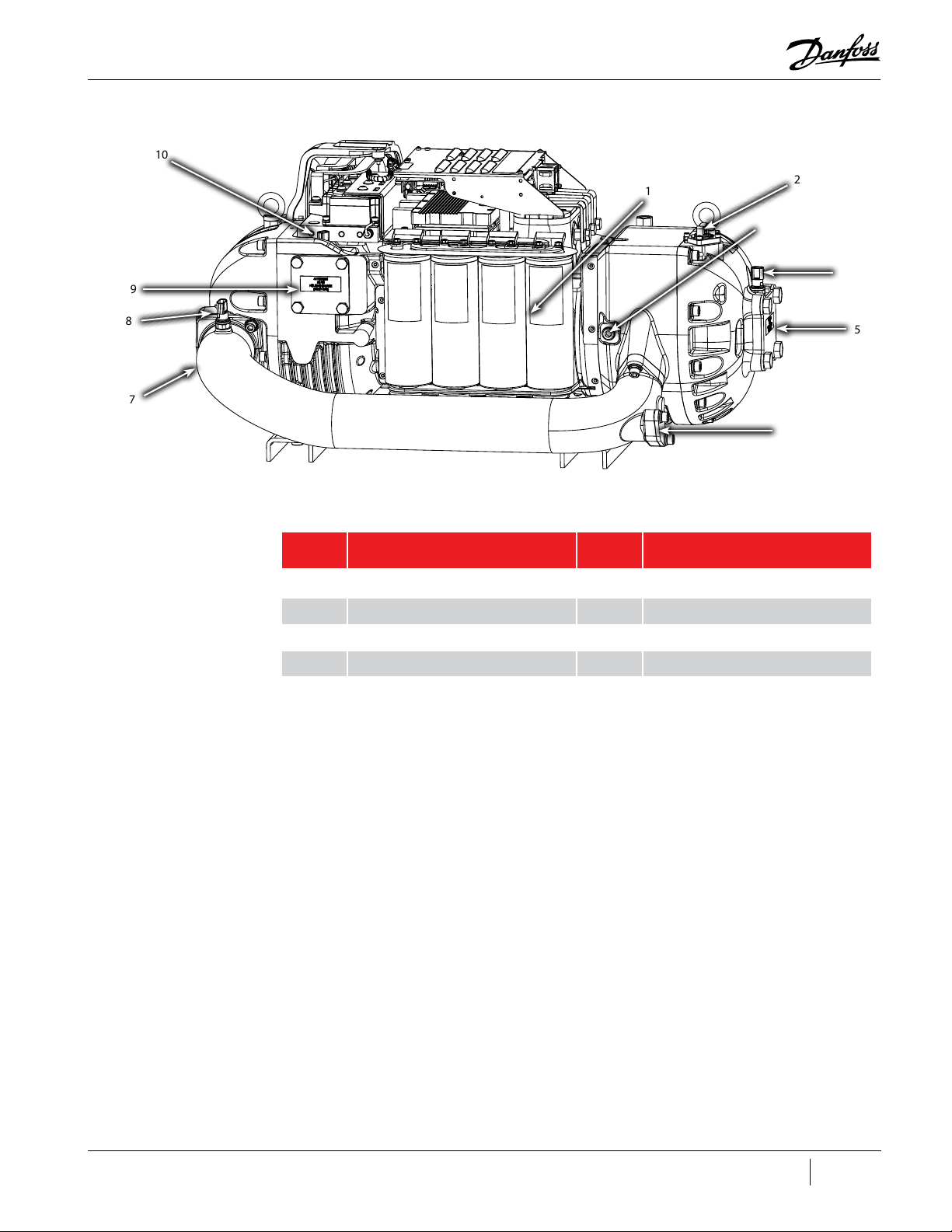
Figure 4-5 Compressor Component Identification - Capacitor Side (TTH/TGH Only)
10
9
1
2
3
4
8
7
Table 4-5 Compressor Components Capacitor Side (TTH/TGH Only)
No. Component No. Component
1 Capacitors 6 Economizer Port
2 IGV Motor Feedthrough 7 Interstage Pipe
3 Optional Pressure Regulating Port 8 Interstage Temperature/Pressure Sensor
4 Suction Temperature/Pressure Sensor 9 Discharge Port
5 Suction Port 10 Interstage Temperature/Pressure Sensor
5
6
M-SV-001-EN Rev. G
55 of 282
Page 56

4.2 Compressor Covers
Figure 4-6 Top Covers Removal
The compressor covers provide protection to the internal components as well as protection for anyone
that might be near the compressor while the mains power is applied and while the capacitors contain
a dangerous electrical charge.
Mains Input
Cover
Top Cover
Care must be taken in removal and installation of the covers to prevent the fasteners from falling in to the power electronic compartment. Dropping cover fasteners can cause a short circuit, cause energized components to explode, and cause damage to the
power electronic parts of the compressor. After properly positioning the covers, carefully install the fasteners to minimize the risk
of them falling into the power electronic areas.
4.2.1 Mains Input Cover
4.2.1.1 Mains Input Cover Removal and Installation
Mains Input Cover Removal
1. Remove the M5x15 fasteners that secure the Mains Input Cover and remove the cover.
Mains Input Cover Installation
1. Ensure that no residue remains on the contact surfaces of Mains Input Cover and Top Cover.
2. Place the Mains Input Cover and secure it with the M5x15 fasteners. Tighten according to the
sequence shown in "Figure 4-7 Mains Input Cover Torque Sequence" on page 57.
56 of 282 M-SV-001-EN Rev. G
• • • CAUTION • • •
Page 57

Figure 4-7 Mains Input Cover Torque Sequence
Mains Cover Fastener,
M5x15
4
1
4 places)
3. Follow the sequence twice. The first time, only tighten the fasteners half way down to allow for
adjustment. Tighten the # 4 fastener only once and be sure to not overtighten. Torque to 13
in.lb. on the second pass.
4.2.2 Top Cover
4.2.2.1 Top Cover Removal and Installation
Top Cover Removal
1. Remove the Mains Input Cover by releasing the M5x15 fasteners and remove the cover.
2. Remove the M5x15 fasteners that secure the Top Cover and remove the cover.
Top Cover Installation
1. Ensure that no residue remains on the contact surfaces of Top Cover and casting sides.
2. Place the Top Cover and secure it with the M5x15 fasteners according to the sequence shown
in "Figure 4-8 Top Cover". Follow the sequence twice. The first time, only tighten the fasteners
half way down to allow for adjustments. Torque to 13 in.lb. on the second pass.
Figure 4-8 Top Cover
Top Cover
Fastener,
Torque to 1.5 Nm
(13 in.lb.)
(9 places)
2
6
5
3
7
8
9
4
3
2
1
M-SV-001-EN Rev. G
57 of 282
Page 58

3. Ensure that no residue remains on the contact surfaces of the Mains Input Cover and casting
sides.
4. Place the new Mains Input Cover and secure it with the M5x15 fasteners. Tighten according to
the sequence shown in "Figure 4-7 Mains Input Cover Torque Sequence".
5. Follow the sequence twice. The first time, only tighten the fasteners half way down to allow for
adjustment. Torque to 13 in.lb. on the second pass. Tighten the # 4 fastener only once and use
caution as to not overtighten.
4.2.3 Service Side Cover
The Service Side Cover provides protection for the Backplane, Serial Driver, BMCC, PWM, feed
throughs, and cabling.
Figure 4-9 Service Side Cover
4.2.3.1 Service Side Cover Removal and Installation
Figure 4-10 Service Side Cover
Service Side Cover Removal
1. Remove the M5x15 fasteners that secure the Service Side Cover and remove the cover.
Service Side Cover Installation
1. Ensure that no residue remains on the contact surfaces of the Service Side Cover and
compressor housing sides.
2. Place the Service Side Cover and secure it with the M5x15 fasteners according to the sequence
shown in "Figure 4-10 Service Side Cover".
3. Follow the sequence twice. The first time, only tighten the fasteners half way down to allow for
adjustment. Torque to 13 in.lb. on the second pass.
Service Side Cover Fastener,
M5x15
(6 places)
5 3
1
58 of 282 M-SV-001-EN Rev. G
4
2
6
Page 59

4.2.4 Capacitor Cover
The Capacitor Cover provides protection for the capacitors.
Figure 4-11 Capacitor Cover
4.2.4.1 Capacitor Cover Removal and Installation
Capacitor Cover Removal
1. Remove the M5x15 fasteners that secure the Top Cover and Capacitor Cover to each other.
2. Remove the fasteners that secure the Capacitor Cover. Remove the cover.
3. Remove the nylon nuts under the capacitor assembly, then remove the capacitor relief
membrane.
Figure 4-12 Capacitor Nylon Nuts
Capacitor Cover Installation
1. Install the capacitor relief membrane with the foam side up. Refer to "Figure 4-12 Capacitor
Nylon Nuts" for this and the following step.
2. Install the nylon nuts to the base of the DC Capacitor Bus Bar Assembly, under the main
compressor housing and torque to 7 Nm (62 in.lb.).
Nylon nut
(4 places)
Foam Side Up
3. Place the Capacitor Cover and secure it with the M5x15 fasteners from the Top Cover.
4. Place the Capacitor Cover on the compressor and loosely secure it with the M5X15 fasteners.
The bottom of the cover should rest just above the Relief Membrane. Refer to "Figure 4-13
Relief Membrane Position" on page 60. Additionally, the cover should line up and sit in the
recessed holes in the compressor housing. Refer to "Figure 4-14 Recessed Holes".
M-SV-001-EN Rev. G
59 of 282
Page 60

Figure 4-13 Relief Membrane Position
Figure 4-14 Recessed Holes
Relief membrane
should be visible
when Capacitor
Cover is installed
5. Place the long M5x20 fastener and flat washer in position number three (3) shown in "Figure
4-15 Capacitor Cover Torque Sequence". Use the remaining M5x15 fasteners to secure the
cover. Tighten all fasteners according to the sequence in "Figure 4-15 Capacitor Cover Torque
Sequence". Torque to 13 in.lb. on the second pass.
Figure 4-15 Capacitor Cover Torque Sequence
4
5
Capacitor Cover
Fastener,
M5x15
(5 places)
6
4.2.5 Compressor Cover Torque Specifications
Table 4-6 Compressor Cover Torque Specifications
Description Nm Ft.Lb. In.Lb.
1
2
Capacitor Cover
Fastener,
M5x20
3
60 of 282 M-SV-001-EN Rev. G
Cover Fastener, M5x15 1.5 - 13
Cover Fastener, M5x20 (#3 on Capacitor Cover) 1.5 - 13
Page 61

4.3 Cooling Adapter
To provide cooling for the motor and power electronics, a liquid feed line is connected to the
compressor via the Cooling Adapter. This adapter contains a strainer to collect any debris that may be
present.
• • • CAUTION • • •
A filter/drier must be used in conjunction with the Cooling Adapter strainer is not a replacement. The strainer is used as a backup
to prevent damage to the solenoid orifices should any debris get past the filter/drier.
Figure 4-16 Cooling Adapter - Excludes TTH375/TGH285
Braze Sleeve
Nut
Inside thread 13/16
UN-2A
11 Nm (8 ft.lb.)
Figure 4-17 Cooling Adapter - TTH375/TGH285)
Strainer
O-ring
Adapter Body
Connection thread
M16x1.5
25 Nm (18 ft.lb.)
O-ring
Nut
Inside thread 13/16
UN-2A
11 Nm (8 ft.lb.)
Braze Sleeve
Adapter Body
Connection thread
M16x1.5
25 Nm (18 ft.lb.)
O-ring
Strainer
O-ring
M-SV-001-EN Rev. G
61 of 282
Page 62

4.3.1 Cooling Adapter Removal and Installation
Cooling Adapter Removal
1. Isolate the compressor and recover the refrigerant according to industry standards. Refer to
"3.1 Refrigerant Containment" on page 41.
2. Hold the Adapter Body with a 15/16" flare nut wrench while loosening the Connection Nut
with another 15/16" flare nut wrench.
3. Remove the line away from the Adapter Body.
4. Remove the Adapter Body with a 15/16" flare nut wrench.
5. Remove O-ring from the compressor housing if it does not come out with the Adapter Body.
Cooling Adapter Installation
1. Verify the threads in the compressor housing are clean and free of debris (do not use
compressed gas to clean the threads as this may blow the debris into the compressor).
2. Clean and lubricate the O-ring. Install onto the cooling adapter body.
3. Insert the cooling adapter body into the compressor and finger tighten.
4. Torque the cooling adapter body to the compressor housing to 25 Nm (18 ft.lb.).
5. Install the screen inside the cooling adapter.
6. Install the braze sleeve and nut minus the O-ring. Tighten the nut finger tight against the
Cooling Adapter. This will allow for the measurement and fitting of the liquid line. Once the
measuring and fitting of the liquid line has been completed, unscrew the nut from the cooling
adapter body and complete the brazing of the liquid line to the braze sleeve.
7. Once the Cooling Adapter assembly has cooled, install the O-ring into the Cooling Adapter and
the finger tighten the nut. Torque the nut to 11 Nm (8 ft.lb.).
8. Leak test and evacuate compressor in accordance with standard industry practices."
A magnet may need to be placed on the motor cooling solenoids if evacuation cannot be performed directly to the liquid line.
9. Return the compressor to normal operation.
4.3.2 Cooling Adapter Torque Specifications
Table 4-7 Cooling Adapter Torque Specifications
Description Nm Ft.Lb. In.Lb.
Adapter Body Connection 25 18 221
Nut 11 8 97
NOTE
62 of 282 M-SV-001-EN Rev. G
Page 63

4.4 Compressor Interface Module
D1 D2 D3 D4 D5 D6 D7 D8
The Compressor Interface Module (CIM), also referred to as the Compressor I/O Board, allows the
user to control the compressor and allows the compressor to return status and sensor information to
the user. See "Figure 4-18 Compressor Interface Module Ports & Jumpers" for I/O board connection
locations.
Figure 4-18 Compressor Interface Module Ports & Jumpers
Table 4-8 CIM Ports and Jumpers
J1
JP2
D9
J7
JP7
J4
No. Component No. Component
J1 RS-485 Communication Port JP1 Analog Output Voltage
J2 Input/Output JP2 MODBUS Terminator
J3 Input/Output JP3 Entry
J4 EXV1 and EXV2 Control JP4 Leave
J2 J3JP1
J8J5
JP3
JP4
JP5
JP6
J6
J5 Liquid Level Input JP5 LIQ LEV1
J6 RS232 I/O Cable Connection JP6 LIQ LEV2
J7 RS232 External Communication Port JP7 J7 Power
J8 External Sensor Inputs
4.4.1 Compressor Interface Module Connection Descriptions
J1 – RS-485 external communication port
• Jumper JP2 required at end of Modbus line
J2 – Input/output
• DEMAND – Pin 1 & 2 – Analog input to drive compressor (0-10V)
• I/LOCK – Pin 3 & 4 – Interlock safety switch: must be part of a closed circuit to start compressor
• STATUS – Pin 5 & 6 – Output; closed circuit: compressor in normal operation; open circuit:
compressor in alarm condition.
• SPEED – Pin 7 & 8 – compressor motor speed output (0-5V = 10,000 RPM/volt)
No longer available for compressors running BMCC firmware versions CC3.0 and later.
NOTE
M-SV-001-EN Rev. G
63 of 282
Page 64

• LIQT – Pin 9 & 10 – Liquid temperature sensor input
• Refer to the Applications and Installation Manual for thermistor specifications
J3 – Input/output
• RUN – Pin 1 & 2 – compressor running indicator output. Normally Open, closes when RPM
reaches specified RPM set in BMCC
• ANALOG – Pin 3 & 4 – Output dependent on BMCC setting. 0-5V or 0-10V set by jumper JP1
• ENTRY – Pin 5 & 6 – Entering chilled fluid temperature sensor input
– Use ENTRY jumper when no sensor connected
– Refer to the Applications and Installation Manual for thermistor specifications
• LEAVE – Pin 7 & 8 – Leaving chilled fluid temperature sensor input
– Use LEAVE jumper when no sensor connected
– Refer to the Applications and Installation Manual for thermistor specifications
J4 – EXV 1 & EXV 2 Control – 15V output
• EXV1 – Pin 6 to 9
• EXV2 – Pin 1 to 4
J5 – Liquid Level input
• LIQ LEV 1 – Pin 4 to 6 – Liquid level sensor driving the electronic expansion valve1 (EXV1)
• LIQ LEV 2 – Pin 1 to 3 – Liquid level sensor driving the electronic expansion valve2 (EXV2)
• Refer to the Applications and Installation Manual for further information
• Jumpers JP5 (LIQ LEV 1) & JP6 (LIQ LEV 2)
– For use with a voltage-type level sensor (with 15V supply and 0-5V signal)
» Install jumpers between LVL pins 2a and 3a, and Pins 2b and 3b
» Connect the sensor leads to the “+,” “S,“ and “-“ terminals on the Compressor I/O Board
(consult vendor documentation for sensor lead identification)
– For use with a resistive-type float sensor
» Install jumpers between LVL Pins 1a and 2a, and Pins 1b and 2b
» Connect the sensor leads to the “-” and “S” terminals on the Compressor I/O Board
– When using Superheat Control (no sensor connected)
» Install jumpers between LVL pins 2a and 3a, and Pins 2b and 3b
64 of 282 M-SV-001-EN Rev. G
J6 – RS-232 I/O Cable connection
• Communication port with Backplane
J7 – RS-232 external communication port
• Use Jumper JP7 only to supply power at the 9-pin connector
J8 – External sensor inputs
• Spare T: External temperature sensor input
– Refer to the Applications and Installation Manual for thermistor specifications
• Spare P: External pressure sensor input
– Refer to the Applications and Installation Manual for pressure sensor specifications
– Refer to the OEM Programming Manual for software implications
D1 to D8 – EXV LED indicators
• Red: 2 sets of 4 LEDs for EXV 1 & EXV 2
Page 65

D9 – Power LED
• Green: ON: compressor is on (i.e., Compressor I/O Board and BMCC are properly connected to
the Backplane)
4.4.2 Compressor Interface Module Verification
4.4.2.1 Determining if the Compressor Interface Module is Draining Energy
1. Identify if the D9, green light-emitting diode (LED) is on.
2. Remove the Service Side Cover.
3. Measure the Backplane +5V and +15V test point voltages.
4. Remove all external connections to the I/O board.
5. Measure the Backplane +5V and +15V test point voltages.
6. Isolate compressor power and wait for the Backplane LEDs to turn off.
7. Disconnect the compressor I/O cable from the J6 connector on the CIM.
8. Apply power to the compressor.
9. Measure the Backplane +5V and +15V test point voltages.
10. If voltages do not change, I/O board is not draining energy.
4.4.2.2 Compressor Interface Module Communication Verification
1. Connect the CIM to a computer.
2. Confirm serial port to be used by the computer.
3. Open the Service Monitor Tool (SMT) software and select the Compressor Connection
Manager tool. See the Service Monitoring Tools User Manual for use instructions.
4. Click Connect.
• If the Compressor Connection Manager is able to connect to the compressor, the BMCC is
able to communicate with the user interface.
• If the system is not able to connect, verify:
– The D9, green LED is on.
– The cable connection between the Backplane (port J7) and the CIM (port J6) is properly
attached.
– The cable connection between the CIM (at port J1 if using RS485 communication or at
port J7 if using RS232 communication) and the user’s computer is properly attached.
– The BMCC is properly connected to the Backplane.
5. If all connections are properly attached and you still cannot connect to the compressor
with the SMT, confirm computer serial port, then use the Search function in the Compressor
Connection Manager to determine the correct baud rate and slave address of the compressor.
Refer to the Service Monitoring Tools User Manual for use instructions.
6. If you can still not connect to the compressor, verify the Backplane and the BMCC.
4.4.2.3 Interlock Verification
1. Ensure the compressor interface cable is properly attached to the Backplane and to the CIM
and the BMCC is properly attached to the Backplane.
2. Remove the J2 connector from the I/O board.
3. Using a multimeter set for DC voltage, measure the voltage between I/LOCK+ and I/LOCK-.
• The voltage should be 2.2 - 3.7VDC.
4. Install the J2 connector to the CIM.
5. Ensure the circuit connected to I/LOCK+ and I/LOCK- on the CIM (port J2) is closed.
6. Measure the voltage at I/LOCK- to the common ground point.
M-SV-001-EN Rev. G
65 of 282
Page 66

• The measured value at I/LOCK- should be 0VDC.
– If the measured value is not 0VDC, locate and remove the source of the voltage.
7. Open the SMT Compressor Monitor tool.
8. With the system interlock circuit remaining closed, verify the Compressor Interlock Status states
“Closed.”
• If the Compressor Interlock Status states “Open,” the interlock circuit is damaged and the
BMCC needs to be replaced.
9. Isolate compressor power.
10. Remove the J2 connector from the CIM.
11. Using a multimeter for resistance measurement. Place the meter probes on I/LOCK+ and I/
LOCK-.
• Resistance should be < 22.2kΩ; if not, the interlock circuit is damaged and the BMCC needs
to be replaced.
• Refer to "5.5.3 Troubleshooting an Open Interlock" on page 259 for further details.
4.4.3 Compressor Interface Module Removal & Installation
Ensure there is no secondary power source connected to the Compressor I/O Board before disconnecting the I/O cable.
4.4.3.1 Compressor Interface Module Removal
1. Isolate compressor power and wait for the D9 LED to turn off on the CIM.
2. Remove all external connections from the CIM.
3. Using a screwdriver, apply leverage toward the left while lifting the right side of the CIM. See
"Figure 4-19 Removing the Compressor Interface Module from the DIN Rail".
4. Repeat the procedure for the other mounting foot to disengage the CIM from the DIN rail.
• • • DANGER • • •
Figure 4-19 Removing the Compressor Interface Module from the DIN Rail
Cross Section of
Interface Module Housing
DIN Rail
4.4.3.2 Compressor I/O Board Installation
1. Install the left foot of the replacement board into the rail and press the right side of the board
down until it engages the rail.
2. Reconnect all external connections and wiring on the CIM.
3. Return the compressor to normal operation.
4.5 Compressor Interface Cable
The Compressor Interface Cable connects the compressor to the CIM. Refer to "Figure 4-20
Compressor Interface Cable" on page 67 for an overall view of the cable installation.
The Rear Bearing Sensor Cable has been removed for clarity.
NOTE
66 of 282 M-SV-001-EN Rev. G
Page 67

Figure 4-20 Compressor Interface Cable
Compressor Interface
Cable
4.5.1 Compressor Interface Cable Verification
If any communication problems exist, verify the integrity of the cable assembly. This can be
accomplished by performing a continuity test at each corresponding pin.
Grommet
Notch for cable
4.5.2 Compressor Interface Cable Removal and Installation
4.5.2.1 Compressor Interface Cable Removal
1. Isolate compressor power as described in Section "1.8 Electrical Isolation" on page 19.
2. Wait for the green light (D9) on the CIM to turn off.
3. Remove the Service Side Cover. Refer to "4.2.3.1 Service Side Cover Removal and Installation"
on page 58.
4. Use a flat-blade screwdriver to disengage the connector screw from the backplane.
5. Disengage the connector thumbscrew from the CIM.
6. Remove the cable by grasping each connector (J6 on CIM and J7 on Backplane) and pulling
away from the board connectors.
4.5.2.2 Compressor Interface Cable Installation
1. Install the cable into the J6 connector on the CIM and the J7 connector on the Backplane.
2. Tighten the connectors to secure the cable.
3. Ensure the cable is routed properly and that the grommet is properly positioned in the
compressor housing notch.
4. Install the Service Side Cover. Refer to "4.2.3 Service Side Cover" on page 58.
5. Return the compressor to normal operation.
4.6 Compressor Controller Cable Harness
The Compressor Controller Cable Harness passes signals from the sensors on the compressor to the
Backplane. The following steps provide detail on how to replace the Compressor Controller Cable
Harness. Prior to removal, note the location of the harness routing as this will minimize the installation
time of the new harness.
M-SV-001-EN Rev. G
67 of 282
Page 68

4.6.1 Compressor Controller Cable Connections
Figure 4-21 Compressor Controller Cable Harness Variants
All TTS/TGS Rev. G and
Earlier Compressors
To Suction Pressure/
Temperature Sensor
All TTS/TGS Rev. H
Compressors
To Suction Pressure/
Temperature Sensor
To IGV Connector
To IGV Connector
To Discharge Pressure/
Temperature Sensor
To Discharge Pressure/
Temperature Sensor
To SCR
Temperature
Sensor
To J19 on Backplane
To J18 on Backplane
To J21 on Backplane
To J17 on Backplane
To J18 on Backplane
To J19 on Backplane
To J21 on Backplane
To Interstage Sensor
TTH/TGH Compressors
To Suction Pressure/
Temperature Sensor
To IGV Connector
4.6.2 Compressor Controller Cable Harness Removal and Installation
Compressor Controller Cable Harness Removal
1. Isolate compressor power as described in section "1.8 Electrical Isolation" on page 19.
2. Remove the Service Side Cover. Refer to "4.2.3.1 Service Side Cover Removal and Installation"
on page 58.
3. Remove the Soft Start. Refer to "4.15.3 Soft Start Removal and Installation" on page 112.
To Discharge Pressure/
Temperature Sensor
To J17 on Backplane
To J21 on Backplane
To J19 on Backplane
To J18 on Backplane
68 of 282 M-SV-001-EN Rev. G
Page 69

4. Remove the Terminal Block Assembly (excluding TTS300/TGS230 compressors). Refer to "4.12.2
3-Phase Main Voltage Input Terminal Block Removal and Installation" on page 98.
5. Remove the DC Bus Bar and Capacitor Assembly. Refer to "4.22.3 DC Capacitor Bus Bar
Assembly Removal and Installation" on page 158.
6. Refer to "Figure 4-22 Backplane Connections" and remove the following connectors from the
Backplane:
• Pressure/temperature sensor connectors (J17, J18, and J19)
• IGV motor drive connector (J21)
Figure 4-22 Backplane Connections
All TTH/TGH compressors and all TTS/TGS Major Rev H and later compressors do not contain an SCR Temperature Sensor.
J17 J18 J19
J21
7. Disconnect the cables from the suction and discharge pressure sensors. Refer to "Figure 4-23
Pressure/Temperature and SCR Temperature Sensor Locations - TTS300/TGS230", "Figure 4-25
Pressure/Temperature Sensors - TTH375/TGH285", and "Figure 4-25 Pressure/Temperature
Sensors - TTH375/TGH285" on page 70 for this and the following step.
NOTE
Figure 4-23 Pressure/Temperature and SCR Temperature Sensor Locations - TTS300/TGS230
Cable Harness
TTS300 Rev. F Shown
Suction Sensor
SCR Temperature
Sensor Cable
Discharge Sensor
M-SV-001-EN Rev. G
69 of 282
Page 70

Figure 4-24 Pressure/Temp and SCR Temp Sensor Locations - TTS/TGS
Cable Harness
TTS350 Rev. F Shown
Suction Sensor
Figure 4-25 Pressure/Temperature Sensors - TTH375/TGH285
Cable Harness
Suction Sensor
SCR Temperature
Sensor Cable
Discharge
Sensor
Discharge
Sensor
Interstage Sensor
Figure 4-26 IGV Connector Clamp
8. Disconnect the SCR Manifold Sensor connector.
9. Loosen the M5x16 fastener securing the IGV Connector Clamp and rotate the clamp out of the
way. Refer to "Figure 4-26 IGV Connector Clamp".
10. Remove the harness connector from the IGV Feedthrough.
Cable Clip
11. Remove the DC Capacitor Bus Bar Assembly. Refer to "4.22 DC Capacitor Bus Bar Assembly" on
page 156.
12. Remove the cable harness in stages so the same routing can be followed for the installation.
70 of 282 M-SV-001-EN Rev. G
Compressor Controller Cable Harness Installation
1. Route the cable harness through the hole in the main compressor housing at the service side.
Refer to "Figure 4-27 Cable Passage" on page 71
Page 71

Figure 4-27 Cable Passage
Cable Passage
2. Route the cable harness between the DC-DC Converter and the Inverter. Lay the harness over
the Inverter Plate.
3. Bend the cable harness under the Mains Terminal Block and route it toward the capacitor side
of the compressor.
4. Install the harness onto the IGV Feedthrough.
5. Rotate the clamp over the IGV connector and torque the M5x16 fastener to 25 Nm (18 ft.lb.)
Refer to "Figure 4-26 IGV Connector Clamp".
6. Connect the SCR Manifold Sensor connector (excluding TTH compressors). Refer to "Figure
4-23 Pressure/Temperature and SCR Temperature Sensor Locations - TTS300/TGS230" on
page 69 and "Figure 4-25 Pressure/Temperature Sensors - TTH375/TGH285" for this and the
following step.
7. Connect the cables to the suction and discharge pressure sensors.
8. Insert the molded rubber grommet in the notch in the main compressor housing.
9. Install the four (4) Backplane connectors (J17, J18, J19, and J21).
• Soft Start interface connector (J22)
• Pressure/temperature sensor connectors (J17, J18, and J19)
• IGV motor drive connector (J21)
10. Install the DC Capacitor Bus Bar Assembly. Refer to "4.22 DC Capacitor Bus Bar Assembly" on
page 156.
11. Install the compressor covers. Refer to "4.2 Compressor Covers" on page 56.
12. Return the compressor back to normal operation.
M-SV-001-EN Rev. G
71 of 282
Page 72

4.6.3 Compressor Controller Cable Harness Torque Specifications
Table 4-9 Compressor Controller Cable Harness Torque Specifications
Description Nm Ft.Lb. In.Lb.
IGV Feedthrough Fastener, M5x16 25 18 221
Cover Fastener, M5x15 1.5 - 13
Cover Fastener, M5x20 1.5 - 13
4.7 Solenoids and Coils
The solenoids pass the high-pressure liquid refrigerant to the low pressure motor and/or electronics
cooling path.
4.7.1 Solenoid and Coil Connections
Solenoids are secured to the service side of the compressor housing in the upper left. Refer to "Figure
4-28 Cooling Valve Bodies".
Figure 4-28 Cooling Valve Bodies
Solenoid orifice size will vary between compressor models. The size can be identified by reading the
number engraved into the solenoid orifice body. For solenoid identification by model, reference the
Spare Parts Selection Guide.
Solenoid actuator coils are secured to the solenoids by nuts hand tightened at the back of each
actuator. Refer to "Figure 4-29 Compressor Cooling Solenoid Coils".
Power is supplied to the Coils through the Backplane from the Serial Driver and controlled by signals
from the BMCC to the Serial Driver. The cable is connected to J16 on the Backplane. Refer to "Figure
4-31 Backplane - J16 Connector" on page 73.
Figure 4-29 Compressor Cooling Solenoid Coils
L
R
72 of 282 M-SV-001-EN Rev. G
Page 73

4.7.2 Solenoid Coil Harness
Figure 4-30 Solenoid Coil Harness
4.7.2.1 Solenoid Coil Harness Removal and Installation
For details, refer to "4.7.4.1 Solenoid and Coil Removal" on page 75 and "4.7.4.2 Solenoid and
Actuator Installation" on page 76.
4.7.3 Solenoid Verification
When actuator coils are removed from the solenoids, they must be replaced in the same location. Incorrect installation can result
in damage to compressor components.
4.7.3.1 Resistance Measurement of Cooling Solenoid Coils
1. Isolate compressor power as described in Section "1.8 Electrical Isolation" on page 19.
2. Remove the Service Side Cover. Refer to "4.2.3.1 Service Side Cover Removal and Installation"
on page 58.
3. Disconnect the Compressor-Cooling Solenoid Coil Connector (J16) from the Backplane.
4. Set the multimeter for resistance measurement.
5. Observe the voltage and power specification indicated on the side of the Compressor-Cooling
Coils and refer to "Table 4-10 Solenoid Coil Resistance Ranges" to find the expected resistance
for the left and right Compressor-Cooling Coils.
6. To measure the resistance across the left Compressor-Cooling Solenoid Coil, place the meter
probes at Pins 1 and 3 of the cable connector. Refer to "Figure 4-32 Compressor Cooling
Solenoid Coil Cable Connector" on page 74.
7. To measure the resistance across the right Compressor-Cooling Coil, place the meter probes
at Pins 5 and 6 of the cable connector. Refer to "Figure 4-32 Compressor Cooling Solenoid Coil
Cable Connector" on page 74.
• • • CAUTION • • •
Figure 4-31 Backplane - J16 Connector
Table 4-10 Solenoid Coil Resistance Ranges
Model Voltage Power Resistance
TTS300 starting at
142035030, TTS350,
TTS500, TTS700, T TH375,
TGS230, TGS310, TGS390,
TGS490, TGS520, & TGH375
TTS300 prior to 142035030 24V 4.8W 108Ω – 132Ω
J16
24V 9.3W 56.25Ω – 68.75Ω
M-SV-001-EN Rev. G
73 of 282
Page 74

Figure 4-32 Compressor Cooling Solenoid Coil Cable Connector
4.7.3.2 Output Voltage to Solenoid Coils
1. Remove the Service Side Cover. Refer to "4.2.3.1 Service Side Cover Removal and Installation"
on page 58.
2. The compressor must be running and make a call to enable the cooling solenoid coils for the
LEDs to turn on. The SMT Cooling Mode will indicate "inverter," "motor," or "motor and inverter"
when the software is sending the signal to the coils.
3. To ensure the Serial Driver is providing power to the solenoids, look for the Cool-L and Cool-H
LEDs on the Backplane. Refer to "Figure 4-33 Backplane - Cool LEDs and +24V Test Points".
4. To determine if 24VDC is present at one or both solenoid coils, use a multimeter to test the
back sides of pins 1 & 3 and pins 5 & 6 of the cooling solenoid coils WHILE they are energized.
Refer to "Figure 4-32 Compressor Cooling Solenoid Coil Cable Connector".
1 2 3
4 5 6
Figure 4-33 Backplane - Cool LEDs and +24V Test Points
+24 Test Point
4.7.3.3 Cooling Path Blockage Inspection
1. Isolate compressor power as described in Section "1.8 Electrical Isolation" on page 19.
2. Isolate the compressor and recover the refrigerant according to industry standards. Refer to
"3.1 Refrigerant Containment" on page 41.
3. Remove the actuators, solenoids, and orifices.
4. Remove the Liquid Line connection from the compressor and inspect the strainer.
5. Ensure that the cooling paths are clean, as shown in "Figure 4-34 Solenoid Cooling Path
- TTS300/TGS230".
Cool-L & Cool-H
LEDs
Figure 4-34 Solenoid Cooling Path - TTS300/TGS230
Cooling Paths
74 of 282 M-SV-001-EN Rev. G
Page 75

4.7.4 Solenoid and Coil Removal and Installation
On current TTS350, T TS400, TTS500, TTS700, TGS310, TGS390, TGS490, TGS520, and certain T TS300 models, the solenoid valve
bodies may have different orifice sizes due to the split-cooling configuration. It is important to not get the left and right confused
when removing and installing these solenoid bodies. See "Figure 4-29 Compressor Cooling Solenoid Coils" on page 72.
Removal of the compressor solenoids will release refrigerant. Isolation and recovery of the refrigerant must be performed by a
qualified service technician adhering to industry/ASHRAE standards.
4.7.4.1 Solenoid and Coil Removal
1. Isolate the compressor power as described in Section "1.8 Electrical Isolation" on page 19.
2. Isolate the compressor and recover the refrigerant according to industry standards. Refer to
"3.1 Refrigerant Containment" on page 41.
There is no need to recover the refrigerant if only the solenoid coils are being removed.
3. Remove the Service Side Cover. Refer to "4.2.3.1 Service Side Cover Removal and Installation"
on page 58.
4. Disconnect the Solenoid Coil J16 connector from the Backplane. Refer to "Figure 4-31
Backplane - J16 Connector" on page 73.
5. Remove the Solenoid Retaining Nuts and the Beveled Washers, then remove the Solenoid Coils.
Refer to "Figure 4-35 Solenoid Component Removal" for this and the following four (4) steps.
6. Remove the Solenoid/Tube Plungers using a six-point 13mm deep socket.
7. Remove the O-rings from the Solenoid Tube/Plungers if plungers are to be reused.
8. Remove the Orifice Valves using a 15/16" socket.
9. Remove the two (2) O-rings from the Orifice Valves if the valves are to be reused.
NOTE
• • • CAUTION • • •
NOTE
Figure 4-35 Solenoid Component Removal
Solenoid
Actuator Coils
(2 places)
Beveled Washer
(2 places)
Small O-ring
(2 places)
Large O-ring
(2 places)
Orifice Valve
(2 places)
Solenoid/Tube
Plunger
(2 places)
Solenoid
Retaining Nut
(2 places)
M-SV-001-EN Rev. G
75 of 282
Page 76

4.7.4.2 Solenoid and Actuator Installation
1. Ensure that all components and threads are clear, clean, and oil free.
2. Lubricate the small and large new O-rings with O-ring lubricant and install them on the Orifice
Valve.
3. Insert the Orifice Valves into the compressor housing and engage the first few threads by hand.
4. Tighten the Orifice Valves with a 15/16" socket and torque to 7 Nm (62 in.lb.).
5. Lubricate the O-rings for the Solenoid Tube/Plungers with O-ring lubricant and install them on
the Solenoid Tube/Plungers.
6. Insert the Solenoid Tube/Plungers into the Orifice Valves and engage the first few threads by
hand.
7. Tighten the Solenoid/Tube Plungers using a six-point 13mm deep socket and torque to 4 Nm
(35 in.lb.).
8. Leak test and evacuate compressor in accordance with standard industry practices.
9. Install the Solenoid Coils in their proper location. For split cooling models, the coil positions
are dedicated. The right-side coil can be identified by an “R” affixed to the coil. The left-side
coil can be identified by an “L” affixed to the coil. Refer to "Figure 4-36 Solenoid Actuator Coil
Position".
Figure 4-36 Solenoid Actuator Coil Position
Motor Cooling
10. Install the Beveled Washers and Solenoid Retaining Nuts to secure the Solenoid Actuator Coils.
Only hand tighten the Solenoid Retaining Nuts. Do not use pliers to install.
11. Reconnect the Solenoid Coils to J16 on the Backplane.
12. Install the compressor covers. Refer to "4.2 Compressor Covers" on page 56.
13. Return the compressor to normal operation.
4.7.4.3 Solenoid Torque Specifications
Table 4-11 Solenoid Torque Specifications
Electronics
Cooling
Install on left
side
• • • CAUTION • • •
Install on right
side
L
R
76 of 282 M-SV-001-EN Rev. G
Description Nm Ft.Lb. In.Lb.
Solenoid Tube/Plunger 4 - 35
Orifice Valve 7 - 62
Cover Screw, M5x15 1.5 - 13
Page 77

4.8 Interstage Pipe - TTH/TGH
The Interstage Pipe may be removed if it is damaged or if there is a refrigerant leak between the
mating surfaces.
Figure 4-37 Interstage Pipe
4.8.1 Interstage Pipe Removal and Installation
4.8.1.1 Interstage Pipe Removal
1. Isolate compressor power.
2. Isolate the compressor and recover the refrigerant according to industry standards. Refer to
"3.1 Refrigerant Containment" on page 41.
3. Disconnect the Interstage P/T Sensor harness.
4. Disconnect the pipe connected to the Economizer port.
5. Remove the four (4) M10x40 fasteners (2 per side) and remove the Interstage Pipe.
6. Remove the O-rings from the flanges.
Figure 4-38 Interstage Pipe Removal
P/T Sensor
O-ring
(2 places)
Interstage Pipe
Fastener,
M10x40
(4 places)
4.8.1.2 Interstage Pipe Installation
1. Clean all mating surfaces.
2. Obtain two (2) new O-rings for the Interstage Pipe and lubricate them with O-lube.
3. Install the new O-rings into the grooves of the Housing Extension and the Second Stage
4. Carefully line up the Interstage Pipe and insert a fastener into each flange.
5. Install the remaining two (2) fasteners finger tight.
6. Torque all four (4) M10x40 fasteners evenly to 32 Nm (24 ft.lb.).
7. Connect the Economizer flange and torque the M10x30 fasteners to 32 Nm (24 ft.lb.).
8. Lubricate the new P/T Sensor O-ring and install into the Interstage Pipe. Torque to 10 Nm (7
9. Connect the Sensor Harness.
10. Leak test and evacuate compressor in accordance with standard industry practices.
Economizer
Port
Suction Housing.
ft.lb.).
M-SV-001-EN Rev. G
77 of 282
Page 78

A magnet may need to be placed on the motor cooling solenoids if evacuation cannot be performed directly to the liquid line.
11. Return the compressor to normal operation.
4.8.2 Interstage Pipe Torque Specifications
Table 4-12 Interstage Pipe Torque Specifications
Description Nm Ft.Lb. In.Lb.
Interstage Pipe Fastener, M10x40 32 24 283
Economizer Flange Fastener, M10x30 32 24 283
P/T Sensor 10 7 89
4.9 Compressor Housing End Cap
The Compressor Housing End Cap may be removed if it is damaged or if there is a refrigerant leak
between the mating surfaces.
There are no field-serviceable components inside of the Compressor Housing End Cap. After the
assembly of the compressor, its function is to prevent refrigerant from escaping. It also contains an
eyebolt to allow for installation and removal of the compressor.
Figure 4-39 Compressor Housing End Cap - T TS/TGS
NOTE
Figure 4-40 Compressor Housing End Cap - TTH/TGH
Compressor Housing
End Cap Fastener,
M10x40
(12 places)
Compressor
Housing End Cap
Fastener,
M10x40
(8 places)
78 of 282 M-SV-001-EN Rev. G
Page 79

4.9.1 Compressor Housing End Cap Removal and Installation
4.9.1.1 Compressor Housing End Cap Removal
1. Isolate compressor power.
2. Isolate the compressor and recover the refrigerant according to industry standards. Refer to
"3.1 Refrigerant Containment" on page 41.
3. Remove the Interstage Pipe (TTH/TGH compressors only). Refer to "4.8.1 Interstage Pipe
Removal and Installation" on page 77.
4. Remove the End Cap.
a. For TTS/TGS compressors remove the eight (8) M10x40 fasteners that secure the
Compressor Housing End Cap to the compressor housing and remove the End Cap. Refer
to "Figure 4-39 Compressor Housing End Cap - TTS/TGS" on page 78.
b. For TTH/TGH compressors, remove the 10 M10x40 fasteners that secure the Compressor
Housing End Cap to the compressor housing and remove the End Cap. Refer to "Figure
4-40 Compressor Housing End Cap - TTH/TGH" on page 78.
5. Remove and discard the O-ring.
4.9.1.2 Compressor Housing End Cap Installation
1. Ensure that all components and threads are clear, clean, and oil free.
2. Clean, lubricate, and install the O-ring into the groove in the compressor housing.
3. Carefully line up the Compressor Housing End Cap and loosely install several of the M10x40
fasteners to hold the end cap in place. Refer to "Figure 4-39 Compressor Housing End Cap TTS/TGS" and "Figure 4-40 Compressor Housing End Cap - TTH/TGH".
4. Install the remaining fasteners and torque fasteners in a crisscross pattern to 32 Nm (24 ft.lb.).
5. Install the Interstage Pipe (TTH/TGH compressors only). Refer to "4.8.1 Interstage Pipe Removal
and Installation" on page 77.
6. Leak test and evacuate compressor in accordance with standard industry practices.
7. Return the compressor back to normal operation.
4.9.1.3 Compressor Housing End Cap Torque Specifications
Table 4-13 Compressor Housing End Cap Torque Specifications
Description Nm Ft.Lb. In.Lb.
Compressor Housing End Cap Fastener, M10x40 32 24 283
Interstage Pipe Fastener, M10x40 32 24 283
Economizer Flange Fastener, M10x30 32 24 283
M-SV-001-EN Rev. G
79 of 282
Page 80

4.10 IGV
Figure 4-41 IGV Assembly
4.10.1 IGV Connections
The IGV assembly consists of movable vanes and a motor. The IGV assembly is a variable-angle guiding
device that is used to control the capacity at low-load conditions. The IGV position can vary between
approximately 0% (closed/perpendicular to flow) and 100% (open/parallel to flow). The vane angle is
determined by the BMCC and controlled by the Serial Driver. The Serial Driver, in turn, uses +15VDC to
control the IGV stepper motor.
Refer to "Figure 4-42 IGV Connections" for the location of the IGV connections.
Figure 4-42 IGV Connections
Table 4-14 IGV Components
1
No. Component
1 The IGV assembly is bolted to the compressor housing.
2 The compressor controller cable is held to the IGV Motor feed through by the cable clip.
3 The compressor controller cable continues on to the suction pressure/temperature sensor.
2
3
4
5
80 of 282 M-SV-001-EN Rev. G
4 The suction pressure/temperature sensor is connected to the IGV Housing.
5 IGV Position Indicator.
Page 81

4.10.2 IGV Verification
4.10.2.1 IGV Stepper Motor Verification
1. Isolate compressor power..
2. Disconnect the IGV Motor Cable from the suction pressure/temperature sensor and the IGV
Motor power feedthrough. Refer to "Figure 4-43 IGV Motor Feedthrough" for this and the
following step.
3. Measure the resistance between terminals 1 and 2, and 3 and 4 of the IGV Motor feed through.
The measured value should be between 46Ω and 59Ω.
4. Measure the resistance between the IGV Motor feed through terminals and the IGV Housing.
The measured value should be open or infinity.
Figure 4-43 IGV Motor Feedthrough
1
2
3
4.10.2.2 IGV Operation Verification
Some of the steps contained within this section require the use of the SMT. Refer to the Service
Monitor Tool Manual regarding the proper usage of the SMT.
1. Remove the Service Side Cover. Refer to "4.2.3.1 Service Side Cover Removal and Installation"
on page 58.
2. Open the SMT installed on your computer and connect to the compressor. Refer to "Figure
4-44 SMT Icon".
Figure 4-44 SMT Icon
3. Open the Compressor Configuration tool. Refer to "Figure 4-45 Compressor Configuration
Tool".
Figure 4-45 Compressor Configuration Tool
4
Cable Clip
M-SV-001-EN Rev. G
81 of 282
Page 82

4. Set the Compressor Control Mode to Manual Control by selecting Manual Control from the
Figure 4-46 Control Mode
5. Open the Compressor Monitor tool. Refer to "Figure 4-47 Compressor Monitor Tool".
Figure 4-47 Compressor Monitor Tool
6. In the IGV Open Percentage parameter box, input 110%. Refer to "Figure 4-48 IGV Open
Compressor Control Mode drop-down list. Refer to "Figure 4-46 Control Mode".
Percentage - 100%".
Figure 4-48 IGV Open Percentage - 100%
7. On the Backplane, there are four (4) LEDs that should light up when the IGV Motor is being
driven. Refer to "Figure 4-50 Backplane Cool LEDs" on page 83.
The LEDs will not remain illuminated once the requested position has been achieved..
8. In the IGV Open Percentage parameter box, input 0%. Refer to "Figure 4-49 IGV Open
Percentage - 0%".
Figure 4-49 IGV Open Percentage - 0%
• Check that all four (4) LEDs are blinking (D13, D14, D15, and D16) and that the IGV position
indicator moves toward open. Refer to "Figure 4-42 IGV Connections" on page 80 for the
location of the IGV Position Indicator.
NOTE
82 of 282 M-SV-001-EN Rev. G
Page 83

9. Check that all four (4) LEDs are blinking. Refer to "Figure 4-50 Backplane Cool LEDs".
Figure 4-50 Backplane Cool LEDs
10. Verify the IGV position indicator moves toward closed.
11. Measure the +15V test point on the Backplane to verify voltage is supplied to the Serial Driver
Figure 4-51 Backplane +15V Test Point
Cool-L & Cool-H
LEDs
IGV Stepper
Motor LEDs
for the IGV. Refer to "Figure 4-51 Backplane +15V Test Point".
+15V Test Point
4.10.3 IGV Housing Removal and Installation
Removal of the IGV mounting fasteners will release refrigerant. Isolation and recovery of the refrigerant must be performed by a
qualified service technician adhering to industry/ASHRAE standards.
4.10.3.1 IGV Housing Assembly Removal
1. Isolate compressor power as described in Section "1.8 Electrical Isolation" on page 19.
2. Remove the clamp securing the IGV Connector. Refer to "Figure 4-52 IGV Harness Removal" for
this and the following step.
3. Disconnect the IGV Motor Cable and Suction Sensor connector.
Figure 4-52 IGV Harness Removal
TTS300 Major Rev F shown
Cable Harness
IGV Motor Feedthrough
• • • CAUTION • • •
Suction Sensor
M-SV-001-EN Rev. G
83 of 282
Page 84

Figure 4-53 IGV Housing Removal
4.10.3.2 IGV Assembly Removal
4. Isolate the compressor and recover the refrigerant according to industry standards. Refer to
"3.1 Refrigerant Containment" on page 41.
5. Remove the 12 M10x40 fasteners that secure the IGV Housing Assembly to the compressor
housing and pull the housing away from the compressor. See "Figure 4-53 IGV Housing
Removal".
IGV Housing
Fastener,
M10x40
(12 places)
1. Remove the IGV Housing Assembly.
2. Remove the four (4) M5x16 fasteners and separate the four-pin Feedthrough from the IGV
Housing. Refer to "Figure 4-54 IGV Feedthrough Removal".
Figure 4-54 IGV Feedthrough Removal
3. Disconnect the four (4) wires from the four-pin Feed Through. Note and record position of wire
colors to their corresponding pins. Expected: 1 = Red, 2 = Gray, 3 = Yellow, and 4 = Black. Refer
to "Table 4-15 IGV Feedthrough Wiring Order".
The colors associated with each pin could vary, so be sure to identify those on the respective compressor.
Table 4-15 IGV Feedthrough Wiring Order
IGV Feedthrough
O-ring
NOTE
Color Pin #
Red 1
Gray 2
Yellow 3
Black 4
IGV Feedthrough
Cable Clip
IGV Feedthrough
M5x16 fastener
(4 places)
84 of 282 M-SV-001-EN Rev. G
Page 85

4. Using a Stepper Motor Driver, turn the worm shaft and Vane Drive assembly to position the
motor shaft so that locking set screw is aligned with the hole shown in "Figure 4-55 Set Screw
Removal". Use needle-nose pliers or similar tool to turn the worm gear if a Stepper Motor
Driver is not available.
5. Remove the set screw completely using a 2.5 mm hex bit to release the motor from the worm
gear.
Figure 4-55 Set Screw Removal
The set screw may be difficult to release as it will have threadlocker applied. For proper engagement into the set screw, do not use
a ball-end hex wrench.
6. Remove the IGV Motor assembly by pulling away from worm shaft. Refer to "Figure 4-56 IGV
Motor Assembly Removal". Support the bottom of the IGV Motor to prevent damage to the
motor shaft. A light tap on the motor locating screw with a hammer may help release the
motor shaft from the worm gear.
Figure 4-56 IGV Motor Assembly Removal
NOTE
M5x8 Set
Screw
Figure 4-57 Locking Collar Tool
7. Slide the Locking Collar Tool (P/N 100246) into the housing and over the worm shaft. Ensure
the drive pins are engaged in the Locking Collar. Refer to "Figure 4-57 Locking Collar Tool".
Locking
Collar Tool,
P/N 100246
Locking
Collar
M-SV-001-EN Rev. G
85 of 282
Page 86

Figure 4-58 Locking Collar Removal
The Locking Collar contains a left-hand thread. To remove, turn clockwise when viewing from the motor end.
Figure 4-59 Worm Gear Removal
8. Turn the Locking Collar clockwise to remove. Refer to "Figure 4-58 Locking Collar Removal".
Drive Pin Holes
Locking Collar
NOTE
9. Remove the worm gear by rotating the IGV Throat clockwise by hand or rotate the worm shaft
by hand. Refer to "Figure 4-59 Worm Gear Removal".
Rotate IGV Throat
clockwise to expel
worm shaft
10. Remove the snap ring from the worm gear shaft. Refer to "Figure 4-60 Large Worm Gear
Bearing Removal" for this and the following step.
11. Remove the upper (large) bearing from the worm gear.
Figure 4-60 Large Worm Gear Bearing Removal
Worm Gear
Large Worm Gear
Bearing
Large Worm Gear
Snap Ring
86 of 282 M-SV-001-EN Rev. G
12. Remove the four (4) M6x55 fasteners that retain the IGV Throat assembly and lift the entire
assembly from the IGV Housing. Refer to "Figure 4-61 IGV Throat Removal" on page 87.
Page 87

Figure 4-61 IGV Throat Removal
IGV Throat
M6x55 fastener
(4 places)
IGV Throat
13. Inspect the IGV Housing assembly for residue/contamination or foreign objects.
14. Remove the small lower worm gear bearing from the housing. Perform this step by pushing
the bearing out from the port below the bearing. Refer to "Figure 4-62 Small Worm Gear
Bearing Removal".
Figure 4-62 Small Worm Gear Bearing Removal
Push from this
end
4.10.3.3 IGV Assembly Installation
Fitting incorrect IGV components for the specific compressor model will result in physical damage to the compressor.
1. Ensure that all components and threads are clear, clean, and oil free.
2. Install the lower (small) worm gear bearing into the housing. This may require a very light tap
with a hammer. Ensure the lower worm gear bearing is fully seated into the housing. Refer to
"Figure 4-63 Small Worm Gear Bearing Installation"
Figure 4-63 Small Worm Gear Bearing Installation
Small Lower
Worm Gear
Bearing
• • • CAUTION • • •
Bearing to fully
seat into housing
M-SV-001-EN Rev. G
87 of 282
Page 88

3. Ensure the IGV position indicator magnet is in place in the IGV Throat assembly. Refer to
"Figure 4-64 IGV Position Indicator Magnet".
Figure 4-64 IGV Position Indicator Magnet
4. Place the IGV Throat assembly into the IGV Housing orientating the IGV Throat threads directly
below the IGV Motor Mount.
5. Add one (1) drop of threadlocker (Loctite 243 blue or equivalent) to the IGV Throat fastener
threads and install. Torque to 5 Nm (44 in.lb.).
6. Rotate the outer ring of the drive assembly and ensure that the guide vanes move freely. The
assembly must rotate over a span where the vanes are open (perpendicular to gas flow) and
fully closed.
7. Fit the upper (large) bearing to the worm gear and install the snap ring. Refer to "Figure 4-65
Large Worm Gear Bearing Installation".
Figure 4-65 Large Worm Gear Bearing Installation
Magnet
Large Worm Gear
Bearing
Large Worm Gear
Snap Ring
Worm Gear
8. Install the worm gear into the housing by “screwing” the worm gear along the IGV Throat Gear.
Locate the worm gear shaft into the bottom (small) bearing.
9. Place the threaded Locking Collar on the four (4) pins of the Collar tool and install into the
housing.
NOTE
Ensure the flat side of the collar is against the tool.
10. Turn the Locking Collar counter clockwise and torque to 5 Nm (44 in.lb.). Refer to "Figure 4-66
Locking Collar Installation" on page 89.
NOTE
Locking collar is a left-hand thread. Turn counter-clockwise when viewed from motor end to tighten (do not use threadlocker on
collar).
88 of 282 M-SV-001-EN Rev. G
Page 89

Figure 4-66 Locking Collar Installation
11. Rotate the worm gear by hand until the set screw hole in the worm gear is visible through the
Figure 4-67 IGV Worm Gear Alignment
Drive Pin Holes
Locking Collar
access hole in the casting. Verify that the worm gear turns freely. Do not install the set screw at
this time. Refer to "Figure 4-67 IGV Worm Gear Alignment".
Worm Gear
Aligned
Figure 4-68 Shaft Position
12. Insert the IGV Motor wires through the Feed Through hole.
13. Check the position of the flat surface of the shaft relative to the locating pin. The flat surface
should be oriented facing up, ready to be inserted in the worm gear. Refer to "Figure 4-68 Shaft
Position".
Check locating
Flat surface of the
shaft facing UP
14. Install the motor into the housing and align the motor shaft flat surface with worm gear
adapter.
15. Ensure the motor locating pin is aligned with the notch in the housing flange. Refer to "Figure
4-69 IGV Motor Alignment" on page 90.
pin position
• • • CAUTION • • •
Check that wiring is clear of housing and edges of motor.
M-SV-001-EN Rev. G
89 of 282
Page 90

Figure 4-69 IGV Motor Alignment
Align locating pin
with notch
Gap=0.5mm
16. Put one (1) drop of threadlocker (Loctite 243 blue or equivalent) on the threads of the small set
screw. While pushing in, on the backside of the motor, secure the worm gear to the flat surface
of the motor shaft using a 2.5 mm hex bit. Rock the motor backwards and forwards while
tightening to ensure full and correct engagement of the screw. Torque the set screw to 5Nm
(44 in.lb.). Refer to "Figure 4-67 IGV Worm Gear Alignment" on page 89.
17. Clean, lubricate, and install the O-ring on the Feed Through before connecting the wires.
18. Insert the motor wires onto the Feed Through pins in accordance with "Table 4-16 IGV
Feedthrough Pin to Wire Reference". Also reference your notes from removal.
The colors associated with each pin could vary, so be sure to refer to notes taken during removal.
Table 4-16 IGV Feedthrough Pin to Wire Reference
19. Position the wires as shown in "Figure 4-70 Motor Wire Position" and "Figure 4-71 IGV Motor
Wires Connected".
Figure 4-70 Motor Wire Position
NOTE
All Except TT300N
Color Pin Number
Red 1
Gray 2
Yellow 3
Black 4
90 of 282 M-SV-001-EN Rev. G
Page 91

Figure 4-71 IGV Motor Wires Connected
20. Install the Feed Through using the four (4) M5x16 fasteners and install the IGV Motor Cable
Retainer Clip under one of the fasteners. Tighten only three (3) of the fasteners to 5Nm (44
in.lb.) while leaving the fourth fastener with the retainer clip slightly loose. Refer to "Figure 4-72
Feedthrough Orientation".
Figure 4-72 Feedthrough Orientation
21. If available, test the motor operation with a stepper motor driver. Operation of the IGV can
22. Clean the mating surfaces of both the compressor and IGV.
23. Clean, lubricate, and install the IGV Housing O-ring.
24. Re-install the IGV on the compressor and finger-tighten the fasteners.
25. Tighten the fasteners in a crisscross pattern to 22 Nm (16 ft.lb.).
Figure 4-73 IGV Housing Installation
Notch in feedthrough should
align with roll pin in the
compressor housing
Do not tighten Retainer Clip
until the harness is installed
also be tested using the SMT driving the IGV manually (once the IGV has been mounted on the
compressor).
IGV Housing
Fastener,
M10x40
(12 places)
26. Leak test and evacuate compressor in accordance with standard industry practices.
M-SV-001-EN Rev. G
91 of 282
Page 92
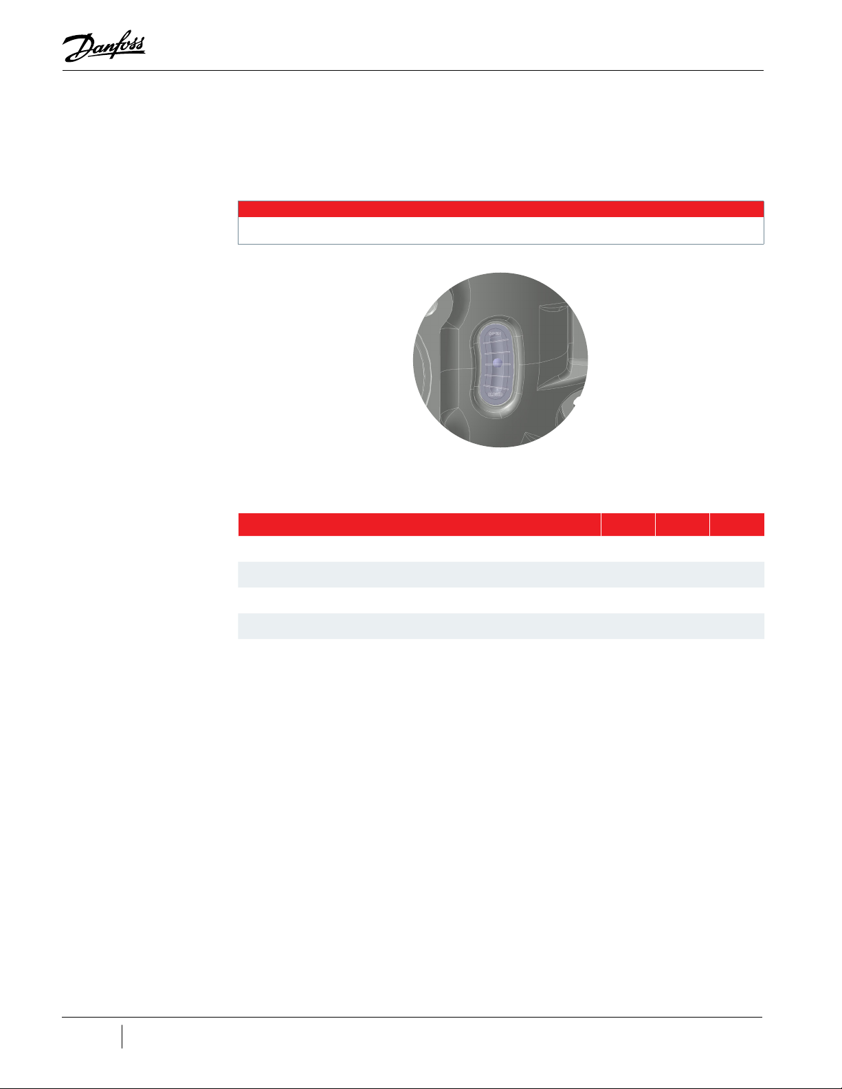
27. Plug in the Feed Through and Suction Pressure Temperature Sensor Harness.
28. Torque the remaining Feed Through fastener (the one securing the Motor Harness Retainer
29. Return the compressor back to normal operation.
30. Test run the compressor to verify proper operation and movement of the IGV assembly. Refer
All IGV assemblies are fully open when the Position Indicator is in the top position.
Figure 4-74 IGV Position Indicator
4.10.4 IGV Torque Specifications
Table 4-17 IGV Torque Specifications
Clip) to 5Nm (44 in.lb.).
to "Figure 4-74 IGV Position Indicator" to verify the position of the IGV.
NOTE
Description Nm Ft.Lb. In.Lb.
IGV Housing Fastener, M10x40 22 16 195
IGV Feedthrough Fastener, M5x16 5 - 44
IGV Motor Setscrew, M5x8 5 - 44
IGV Throat Fastener, M6x55 5 - 44
Locking Collar 5 - 44
92 of 282 M-SV-001-EN Rev. G
Page 93

4.11 Mains Plate Bracket
Figure 4-75 Mains Plate Bracket
TTS350 Rev. F Shown
The Mains Plate is used to secure the mains cables. The Mains Plate is identical across all versions of
the compressors. However, the ground post on the TTS300/TGS230 compressors is located directly
behind the Mains Plate, whereas the ground post for all other compressor models goes through the
Mains Plate and into the compressor housing. The illustrations in this section are of the TTS350 and all
removal and installation steps of the various TTS/TTH/TGS/TGH compressors are the same.
Mains Cover
Upper Nut 5/16" -
18 UNC
Lock Washer
Jam Nut 5/16" -
18 UNC
Lower Nut - 5/16" -
18 UNC
4.11.1 Mains Plate Bracket Removal and Installation
4.11.1.1 Mains Plate Bracket Removal
1. Isolate compressor power as described in Section "1.8 Electrical Isolation" on page 19.
2. Disconnect the mains input cables from the Terminal Block.
3. Disconnect the main input ground cable and Soft Start ground wire from the ground post.
4. Remove the cable gland that secures the mains input cable conduit to the Mains Plate.
5. Remove the two (2) M6x16 fasteners that secure the Mains Plate. Refer to "Figure 4-75 Mains
Plate Bracket" on page 93.
6. Remove the Mains Plate.
Mains Plate
Mounting M6x16
Fastener
(2 places)
5/16"-18X1.5" Set
Cup Point Screw
4.11.1.2 Mains Plate Bracket Installation
1. Install the Mains Plate using the M6x16 fasteners and torque to 7 Nm (62 in.lb.).
2. Install the cable gland.
M-SV-001-EN Rev. G
93 of 282
Page 94

3. Install the Soft Start ground wire on top of the lower nut and torque the jam nut to 7 Nm (62
in.lb). Install the ground cable for the mains on top of the jam nut and torque the upper nut to
10 Nm (7 ft.lb.) Refer to "Figure 4-76 Ground Post Nuts".
Figure 4-76 Ground Post Nuts
Upper Nut - 10 Nm
(7 ft.lb.)
Lock Washer
Jam Nut - 7 Nm
(62 in.lb.)
Lower Nut - 20 Nm
(15 ft.lb.)
4. Install the mains input cables to the Terminal Block and torque to 20 Nm (15 ft.lb.) for TTS300/
TGS230 compressors and torque all others to 21 Nm (15 ft.lb.). Refer to "Figure 4-77 Mains
Input Nut Installation - TTS300/TGS230 Compressors" and "Figure 4-78 Mains Input Nut
Installation - TTS/TGS/TTH/TGH Rev. H and Earlier (Except TTS300/TGS230)".
Figure 4-77 Mains Input Nut Installation - TTS300/TGS230 Compressors
Mains Input Pressure
Screw, 11/16 x 16 - 20 Nm
(15 ft.lb.)
(3 places)
Figure 4-78 Mains Input Nut Installation - TTS/TGS/TTH/TGH Rev. H and Earlier (Except TTS300/TGS230)
Mains Input Nut,
3/8 x 16 - 21 Nm
(15 ft.lb.)
(3 places)
NOTE
The TTS300/TGS230 series compressors do not utilize cable lugs. Because of this, torque specifications will vary depending on the
type of cabling. it is recommended to contact the manufacturer of the cabling used for the appropriate torque specification.
5. Install the top covers. Refer to "4.2 Compressor Covers" on page 56.
6. Return the compressor to normal operation.
94 of 282 M-SV-001-EN Rev. G
Page 95

4.11.1.3 Mains Plate Torque Specifications
Table 4-18 Mains Plate Torque Specifications
Description Nm Ft.Lb. In.Lb.
Mains Plate Mounting Screw, M6x16 7 - 62
Cover Fastener, M5x15 1.5 - 13
Upper Nut, 5/16" - 18 UNC 10 7 89
Jam Nut, 5/16" - 18 UNC 7 - 62
Lower Nut, 5/16" - 18 UNC 20 15 177
Mains Input Nut, 3/8" - 16 UNC (excludes TT300/TG230 compressors) 21 15 186
4.12 3-Phase Main Voltage Input Terminal Block
The Terminal Block is the location where the compressor receives 3-Phase AC voltage, even when not
running. All compressors must be fitted with class T fast-acting fuses to protect the solid-state Inverter.
Danfoss Turbocor control does NOT directly measure 3-phase power values. All 3-phase voltage
information displayed in the SMT is calculated from DC bus voltage and motor power as measured by
the Inverter. The input voltage varies between 380-575VAC at a frequency of 50/60Hz.
There are two (2) different configurations of the Terminal Blocks, one for the TTS300/TGS230 series
and another for all other TTS/TGS/TTH/TGH series. With the introduction of Revision H compressors, all
compressors, except for the TTS300/TGS230 compressors, have an upgraded Terminal Block design.
Refer to "Figure 4-79 Input Terminal Block - TTS300/TGS230" for TTS300/TGS230 compressors. For all
other compressors that are Revision G and earlier, refer to "Figure 4-81 Input Terminal Block - TTS/TGS/
TTH/TGH Rev. F and Earlier (Except TTS300/TGS230)" on page 96 and for all other compressors that
are Revision H, refer to "Figure 4-80 Input Terminal Block - TTS/TGS/TTH/TGH Rev. H (Except TTS300/
TGS230)" on page 96.
Figure 4-79 Input Terminal Block - TTS300/TGS230
Mylar
Fuse Assembly
Terminal
Block
M-SV-001-EN Rev. G
95 of 282
Page 96

Figure 4-80 Input Terminal Block - TTS/TGS/TTH/TGH Rev. H (Except TTS300/TGS230)
AC Bus Bars
Terminal
Block
Figure 4-81 Input Terminal Block - TTS/TGS/TTH/TGH Rev. F and Earlier (Except TTS300/TGS230)
AC Bus Bars
4.12.1 3-Phase Main Voltage Input Terminal Block Verification
4.12.1.1 3-Phase AC input Verification
The compressor requires a 3-phase power source with UL-approved or CE-approved components in
circuit with code-compliant protection.
• This equipment contains hazardous voltages that can cause injury or death. Exercise extreme
caution when working on energized circuits.
• Always wear safety glasses when working around components energized by high voltage. Faulty
components can explode and cause serious eye injuries.
4.12.1.2 Connecting the AC Input Cable
1. Isolate compressor power.
2. Ensure the AC cables are securely fastened to the input Terminal Block.
• • • DANGER • • •
Terminal
Block
96 of 282 M-SV-001-EN Rev. G
Page 97

3. If the cables cannot be securely fastened to the input terminal, the Terminal Block is damaged
and needs to be replaced.
4.12.1.3 Verifying the 3-Phase AC Input
1. Turn ON the AC input power.
2. Set the multimeter for AC voltage measurements.
3. Place the meter probe on one phase of the AC input terminals and the other meter probe on
another phase of the AC input terminals as shown in "Figure 4-82 Measuring the 3-Phase AC
Input Voltage on the AC Input Terminals - TTS300/TGS230" and "Figure 4-83 Measuring 3-Phase
AC Input Voltage on AC Input Terminals (TTS/TGS/TTH/TGH (Except TTS300/TGS230)". Repeat
for all AC input terminals. Repeat on load side of the fuses (TT300/TG230 only).
Figure 4-82 Measuring the 3-Phase AC Input Voltage on the AC Input Terminals - TTS300/TGS230
Figure 4-83 Measuring 3-Phase AC Input Voltage on AC Input Terminals (TTS/TGS/TTH/TGH (Except TTS300/TGS230)
TTS350 Rev. F Shown
4. Verify that the meter shows the expected AC measurement within the range as indicated in
"Table 4-19 Expected AC Voltage Range" on page 98. The acceptable AC input voltage range
is +/-10% of the nameplate AC input voltage.
5. If the meter does not show any reading, it is possible there is no power from the AC source.
Ensure the AC power source is turned ON and try again. If there is no power on the load side of
the fuses (TTS300/TGS230 only), isolate the power and check the fuses.
6. If the measured values correspond to the specified values for all phases, the AC input voltage
is okay.
M-SV-001-EN Rev. G
97 of 282
Page 98

Table 4-19 Expected AC Voltage Range
AC Input
Nameplate Voltage
575VAC 518 to 632VAC
460VAC 414 to 506VAC
400VAC 360 to 440VAC
380VAC 342 to 418VAC
Acceptable Voltage
Range
4.12.2 3-Phase Main Voltage Input Terminal Block Removal and Installation
4.12.2.1 General 3-Phase Main Voltage Input Terminal Block Removal
1. Isolate compressor power as described in Section "1.8 Electrical Isolation" on page 19.
2. Disconnect the mains input cables from the Terminal Block.
3. For TT300/TG230 compressors, continue to Section "4.12.2.2 Specific 3-Phase Main Voltage
Input Terminal Block Removal - TTS300/TGS230"; for all others, continue to Section "4.12.2.3
3-Phase Main Voltage Input Terminal Block Removal - TTS/TGS/TTH/TGH Rev. F and Earlier
(Except TTS300/TGS230)" on page 99.
4.12.2.2 Specific 3-Phase Main Voltage Input Terminal Block Removal - TTS300/TGS230
1. Remove the three (3) M6x16 fasteners that connect the Fast Acting Fuses to the SCRs. Refer to
"Figure 4-84 Terminal Block Removal - TTS300/TGS230" for this and the following four (4) steps.
2. Remove the six (6) Fuse to Terminal Block fasteners that secure the fuses to the Terminal Block
Adapter.
3. Remove the fuses.
4. Remove the insulating Mylar.
5. Remove the Terminal Block fasteners that secure the Terminal Block to the compressor housing
and remove the Terminal Block.
Figure 4-84 Terminal Block Removal - TTS300/TGS230
AC Bus Bar to SCR
Fastener, M6x16,
(3 places)
Terminal Block
Fastener, M5x15,
(3 places)
6. Continue to Section "4.12.2.4 3-Phase Main Voltage Input Terminal Block Installation - TTS300/
TGS230" on page 100.
Fuse to Terminal
Block Fastener
(6 places)
Fuse Assembly
(3 places)
Mylar
Terminal Block
98 of 282 M-SV-001-EN Rev. G
Page 99

4.12.2.3 3-Phase Main Voltage Input Terminal Block Removal - TTS/TGS/TTH/TGH Rev. F and Earlier (Except TTS300/
TGS230)
1. Disconnect the three (3) connectors of the Soft Start AC/DC harness from the bus bars.
2. Remove the three (3) fasteners that secure the AC Bus Bars to the SCRs. For Revision F and
earlier compressors, refer to "Figure 4-85 Input Terminal Block Removal - TTS/TGS/TTH/TGH
Rev. F and Earlier (Except TTS300/TGS230)" and for Revision H compressors, refer to "Figure
4-86 Input Terminal Block Removal - TTS/TGS/TTH/TGH Rev. H (Except TTS300/TGS230)" on
page 100 for this and the following three (3) steps.
3. Remove the six (6) fasteners that secure the three (3) AC Bus Bars to the Terminal Block.
4. Remove the AC Bus Bars.
NOTE
If the terminal block is being removed to access other components, it is not necessary to remove the AC Bus Bars from the
terminal block on Rev F and earlier compressors - the terminal block and bus bars can be removed as an assembly. On Rev H
compressors, the center AC Bus Bar must be removed to access a mounting fastener for the terminal block but the two (2) bus
bars can remain attached.
5. Remove the fasteners that secure the Terminal Block to the casting and remove the Terminal
Block.
a. Rev F and ealier compressors use two (2) M5x45 fasteners that attach the Terminal Block to
the compressor housing.
b. Rev H compressors use three fasteners; it uses the same two (2) as listed above and there
is an additional M6x16 fastener that is located at the back center of the Terminal Block
(under the center AC Bus Bar). This fastener secures the Terminal Block to the SCR Cooling
Plate.
6. Remove the two (2) spacers if the Terminal Block is to be replaced with a new one.
7. Continue to Section "4.12.2.5 3-Phase Main Input Terminal Block Installation - TTH/TGH/TTH/
TGH (Except TTS300/TGS230)" on page 101.
Figure 4-85 Input Terminal Block Removal - TTS/TGS/TTH/TGH Rev. F and Earlier (Except TTS300/TGS230)
AC Bus Bars
AC Bus Bar to Terminal
Block Fastener
Mains Input Nut, 3/8 x 16,
(3 places)
Terminal Block to
Compressor Fastener,
M5x45,
(2 places)
Terminal
Block
AC Bus Bar to SCR
Fastener, M8x20,
(3 places)
M-SV-001-EN Rev. G
99 of 282
Page 100

Figure 4-86 Input Terminal Block Removal - TTS/TGS/TTH/TGH Rev. H (Except TTS300/TGS230)
Mains Input Nut, 3/8 x 16,
(3 places)
AC Bus Bar to Terminal
Block Fastener, M5x12
(6 places)
Terminal Block to
Compressor Fastener,
M5x45,
(2 places)
4.12.2.4 3-Phase Main Voltage Input Terminal Block Installation - TTS300/TGS230
AC Bus Bar to SCR
Fastener, M8x20,
(3 places)
AC Bus Bars
Terminal
Block
Terminal Block to SCR
Cooling Plate Fastener,
M6x16,
(2 places)
Figure 4-87 Input Terminal Block Installation - TTS300/TGS230
AC Bus
Bar to SCR
Fuse Assembly to Terminal Block
Fastener
(6 places)
Terminal Block Mounting
Fastener, M5x15 - 3 Nm
(27 in.lb.)
(3 places)
Mylar
AC Bus Bar to SCR Fastener
M6x16 - 5 Nm (44 in.lb.)
(3 places)
Fuse
Fuse Assembly
Terminal
Block Adapter
Terminal
Block
100 of 282 M-SV-001-EN Rev. G
 Loading...