

Page 1
®
Applications and Installation Manual - Revision S
Danfoss Turbocor® Twin-Turbine
Centrifugal Compressors
TTS/TGS/TTH/TGH Compressors
http://turbocor.danfoss.com |
Page 2

THISPAGEINTENTIONALLYLEFTBLANK
Page 2 of 136 - M-AP-001-EN Rev. S 9/8/2021
Page 3

Table of Contents
Table of Contents 3
Chapter 1.0 Introduction 11
1.1 Scope 11
1.2 Document Symbols 11
Chapter 2.0 Compressor Overview 19
2.1 TTS/TGS/TTH/TGH Compressor Nomenclature 19
2.2 Refrigerant Type 21
2.3 Environment 21
2.4 Configurations of the TTS/TGS/TTH/TGH Compressor Models 22
2.5 Compressor Module 23
Chapter 3.0 Functional Description 25
3.1 Main Fluid Path 25
3.2 Motor Cooling 26
3.3 Inlet Guide Vanes 29
3.4 Compressor Control Overview 30
3.4.1 Motor Drive System 30
3.4.2 Soft Start 31
3.4.3 Bearing Motor Compressor Controller 31
3.4.4 Compressor Control 31
3.4.5 Capacity Control 31
3.4.6 Expansion Valve Control 31
3.4.7 Motor/Bearing Control 31
3.4.8 Monitoring Functions 32
3.4.9 Abnormal Conditions 32
3.4.10 Bearing PWM Amplifier 32
3.4.11 Serial Driver 32
3.4.12 Backplane 32
3.4.13 High-Voltage DC-DC Converter 33
3.5 Magnetic Bearing System 33
M-AP-001-EN Rev. S-9/8/2021 Page 3 of 136
Page 4

3.5.1 Overview 33
3.5.2 Bearing Control System 33
Chapter 4.0 Control Interface Wiring 35
4.1 Control Wiring Connection Guidelines 37
4.2 Interface Cable 38
4.3 Compressor I/O Board Mounting Details 39
4.3.1 Compressor I/O Board Mounting Instructions 39
Chapter 5.0 General Specifications 41
5.1 Construction 41
5.2 Maximum Pressure 41
5.3 Maximum Discharge Temperature 41
5.4 Suction Pressure Limits 42
5.5 Standards Compliance 43
Chapter 6.0 Electrical Specifications 45
6.1 Supply Voltage and Frequency 45
6.2 Voltage Sag Immunity 45
6.3 Compressor Current Limit and Operating Range Settings 45
6.4 Disconnects 47
6.5 Motor Insulation Class 47
6.6 AC Input Line/Power Electronic Component Protection 47
6.7 Power Line Contactor 48
6.8 CE Compliance and EMI/EMC Filtering 48
6.9 Surge Protection 49
6.10 Line Reactor 49
6.11 Harmonic Current Filtering (IEEE 519) 49
6.12 Grounding (Earth) Connection Guidelines 49
6.13 Equipment Panel 50
6.14 Mains Input Cable Specification 51
6.15 Idle Power Consumption 51
Page 4 of 136 - M-AP-001-EN Rev. S 9/8/2021
Page 5

Chapter 7.0 Compressor Performance 53
7.1 Performance Ratings 53
7.2 Tolerance of Performance Ratings 53
Chapter 8.0 Operating Envelopes 55
Chapter 9.0 Minimum Unloading Capacity 67
Chapter 10.0 Control Logic Guidelines for Multiple Compressors 69
Chapter 11.0 Product Certification 71
Chapter 12.0 Guide Specifications 73
12.1 General 73
12.2 Refrigerant 73
12.3 Compressor Bearings 73
12.4 Capacity Control 73
12.5 Compressor Motor 73
12.6 Compressor Electronics 73
12.7 Ancillary Devices 73
Chapter 13.0 System Design Guidelines 75
13.1 General Requirements 75
13.2 Economizer Option 76
13.3 Motor/Electronics Cooling Requirements 76
13.4 Electrical Requirements 77
13.5 Application-Specific Requirements 77
13.5.1 Medium Evaporating Temperature Application (TGS230/TTS300/TGH285/TTH375) 77
13.5.2 High Evaporating Temperature Application (TGS310/TTS350/TGS490/TGS390/TTS400/TGS520/TTS700) 77
13.5.3 Limited Capacity at Low Pressure Ratios 78
13.5.4 Low Lift Application 78
Chapter 14.0 Sample Refrigeration Circuits 81
Chapter 15.0 Sound and Power Specifications 91
15.1 TTS300 and TTS400 Sound Power Measurements 91
15.1.1 Results 91
M-AP-001-EN Rev. S-9/8/2021 Page 5 of 136
Page 6

Chapter 16.0 Physical Data 95
16.1 Clearance 95
Chapter 17.0 Piping Considerations 109
Chapter 18.0 Environmental Considerations 111
18.1 Humidity 111
18.2 Vibration 111
Chapter 19.0 Shipping Considerations 113
19.1 Vibration 113
Chapter 20.0 Installation 115
20.1 Unpacking and Inspection 115
20.2 Rigging Requirements 115
20.3 Unit Placement 115
20.4 Mounting Base 116
20.5 Piping Connections 117
20.6 Control Wiring 118
20.6.1 Control Wiring Connections 118
20.6.2 Circuit Grounding 119
20.6.3 Voltage-Free Contacts 120
20.7 Power Wiring 121
Appendix A 125
A.1 Line Reactor Installation Instructions 125
Appendix B 127
B.1 EMI/EMC Filter Installation Instructions 127
Appendix C 129
C.1 Pressure Regulating Valve Installation Instructions 129
Page 6 of 136 - M-AP-001-EN Rev. S 9/8/2021
Page 7

List of Changes
Revision Date Page Description of Change
P 06-12-2019 Redevelopment of manual
to include TTH/TGH
compressors
P.1 12-12-2019 Update to include TG490
and Medium Temp
Q 04-06-2020 Major Revision H upgrade
R 02-01-2021 Includes High SST and
general review/update
S 07-29-2021 Complete review/many
small changes made
Includes new TTS 575V
option
M-AP-001-EN Rev. S-9/8/2021 Page 7 of 136
Page 8

THISPAGEINTENTIONALLYLEFTBLANK
Page 8 of 136 - M-AP-001-EN Rev. S 9/8/2021
Page 9

Proprietary Notice
Copyright, Limitations of Liability and Revision Rights.
This page contains proprietary information to Danfoss LLC. This publication is protected under the Copyright laws of
the United States of America (USA) and most other countries. This work is owned by Danfoss LLC, and was published
as of the most recent revision of this publication, as indicated on the Title page of this document. This document is
for the use Danfoss LLC customers and prospective customers only. Any use beyond that is prohibited.
Tests have demonstrated that equipment produced according to the guidelines provided in this manual will
function properly, however Danfoss LLC cannot guarantee the equipment to work in every physical, hardware or
software environment.
The guidelines provided in this manual are provided “AS-IS” without any warranty of any kind, either express or
implied, including, without limitation, any implied warranties of condition, uninterrupted use, merchantability,
fitness for a particular purpose.
In no event shall Danfoss LLC be liable for direct, indirect, special, incidental or consequential damages arising out of
the manufacture, use, or the inability to manufacture or use information contained in this manual, even if advised of
the possibility of such damages. In particular, Danfoss LLC is not responsible for any costs, including but not limited
to those incurred as a result of lost profits or revenue, loss of damage or equipment, loss of computer programs, loss
of data, the costs to substitute these, or any claims by third parties. In any event, the total aggregate liability for all
damages of any kind and type (regardless of whether based in contract or tort) of Danfoss LLC, shall not exceed the
purchase price of this product.
Danfoss LLC reserves the right to revise the publication at any time and to make changes to its contents without
prior notice or any obligation to notify former or present users of such revisions or changes.
Danfoss Turbocor Compressors Inc.
1769 East Paul Dirac Drive
Tallahassee, Florida 32310
USA
Phone 1-850-504-4800
Fax 1-850-575-2126
http://turbocor.danfoss.com
Encounter an error or see an opportunity for improvements while reading this manual? Email us at
turbocor.contact@danfoss.com with a brief description.
* Subject to change without notice.
* Danfoss Turbocor’s commitment to excellence ensures continuous product improvements.
M-AP-001-EN Rev. S-9/8/2021 Page 9 of 136
Page 10

THISPAGEINTENTIONALLYLEFTBLANK
Page 10 of 136 - M-AP-001-EN Rev. S 9/8/2021
Page 11

Chapter 1.0 Introduction
This Applications and Installation Manual is intended to be a guide for application data/installation procedures
specific to Danfoss Turbocor compressors. It is not intended to inform on fundamental safety, refrigeration and
electrical design skills. It is assumed and presumed that persons using this manual are appropriately certified and
have detailed knowledge, experience and skills in respect to designing for and working with high pressure
refrigerants and medium voltage electrical components (to 1 KV high power AC & DC) as well as complex control
systems.
Some potential safety situations may not be foreseen or covered in this guide. Danfoss LLC assumes personnel using
this manual and working on Danfoss LLC compressors are familiar with, and carry out, all safe work practices
necessary to ensure safety for personnel and equipment.
1.1 Scope
This manual is designed for use with Bearing Motor Compressor Controller (BMCC) software, Version 4.0.0 and later.
Table 1-1 Application Manual Applicability
Manual Release Date BMCCFirmware Versions
M-AP-001-XX Rev E September 2013 CC 2.3.1213
M-AP-001-XX Rev L October 2016 CC 3.1.4
M-AP-001-XX Rev M November 2017 CC 4.0 and later
M-AP-001-XX Rev M.1 November 2017 CC 4.1 and later
M-AP-001-XX Rev N May 2018 CC 4.1 and later
M-AP-001-XX Rev P.1 November 2019 CC 4.2 and later
M-AP-001-XX Rev R January 2021 CC 4.3 and later
1.2 Document Symbols
The following symbols are used in this document.
NOTE: Provides additional information such as a tip, comment, or other useful, but not imperative information. A
Note is displayed in the format shown below.
NOTE
M-AP-001-EN Rev. S-9/8/2021 Page 11 of 136
Page 12

DANGER: Indicates an essential operation or maintenance procedure, practice, or condition which, if not strictly
observed, could result in injury to or death of personnel or long-term health hazards. A Danger notification is
displayed in the format shown below.
• • • DANGER! • • •
CAUTION: Indicates an essential operation or maintenance procedure, practice, or condition which, if not strictly
observed, could result in damage to or destruction of equipment or potential problems in the outcome of the
procedure being performed. A Caution notification is displayed in the format shown below.
• • • CAUTION • • •
Table 1-2 Acronyms and Terms
Acronym/Term Definition
Alarms Alarms indicate a condition at the limit of the normal operating envelope. Compressor
alarms will still allow the compressor to run, but speed is reduced to bring the alarm
condition under the alarm limit.
AHRI Air-Conditioning, Heating, and Refrigeration Institute (www.ari.org;www.ahrinet.org).
ANSI American National Standards Institute.
ASHRAE American Society of Heating Refrigeration and Air-Conditioning Engineers
(www.ashrae.org).
Axial Bearing Bearing that controls the horizontal movement (Z axis) of the motor shaft.
Backplane A printed circuit board (PCB) for the purpose of power and control signal transmission.
Many other components connect to this board.
BMCC Bearing Motor Compressor Controller. The BMCC is the central processor board of the
compressor. Based on its sensor inputs, it controls the bearing and motor system and
maintains compressor control within the operating limits.
Bus Bars Heavy-gauge metal conductors used to transfer large electrical currents.
Capacitor A passive component that stores energy in the form of an electrostatic field.
Cavity Sensor Negative Temperature Coefficient (NTC) temperature sensor located behind the
Backplane for the purpose of sensing motor-cooling vapor temperature. Provides
Page 12 of 136 - M-AP-001-EN Rev. S 9/8/2021
Page 13

Acronym/Term Definition
overheat protection to motor windings.
CE Conformance European. The CE marking (also known as CE mark) is a mandatory
conformity mark on many products placed on the single market in the European (EU)
Economic Area. The CE marking certifies that a product has met EU health, safety, and
environmental requirements, which ensure consumer safety.
CEC Canadian Electrical Code.
Choke Definitive point on compressor map where mass flow rate is at maximum for compressor
speed and lift conditions.
CIM Compressor Interface Module; the part of the compressor electronics where the user
connects all field connection wiring such as RS-485, EXV and analog / digital wiring. Also
known as the Input/Output (IO) board.
Compression Ratio The absolute discharge pressure divided by the absolute suction pressure.
CPR Compressor Performance Rating.
CSA Canadian Standards Association (www.csa.ca).
dB Logarithmic scale that measures sound and loudness.
dBA Sound level measurement that has been adjusted based on how the human ear perceives
sounds in the air.
DCBus High DC voltage simultaneously connected to multiple compressor components via
metallic bus bars, including the capacitors.
DC-DC Converter DC-DC converters supply and electrically isolate the high and low DC voltages that are
required by the control circuits. When the compressor is switched on, the High-Voltage
(HV) DC-DC Converter receives its 15VAC supply from the Soft-Start Board. Once the DC
DC-DC Converter bus voltage has risen to a pre-determined level, the HV DC-DC
Converter’s onboard circuits are powered by the DC bus (460-900VDC). The HV DC-DC
Converter delivers +24VDC (with respect to 0V) to the Backplane, and HV+ (+250VDC
with respect to HV-) to the magnetic Bearing Pulse Width Modulation (PWM) Amplifier via
the Backplane.
Diffuser Part of a centrifugal compressor in the fluid module that transforms the high-velocity,
low- pressure gas exiting the impeller into higher-pressure, low-velocity gas discharged
into the condenser.
EMC Electromagnetic Compatibility.
M-AP-001-EN Rev. S-9/8/2021 Page 13 of 136
Page 14

Acronym/Term Definition
EMF Electromotive Force.
EMI Electromagnetic Interference.
EMI Filter A circuit or device that provides electromagnetic noise suppression for an electronic
device.
EPDM Ethylene propylene diene monomer – type of synthetic rubber.
ETL ETL Testing Laboratories, now a mark of Intertek Testing Services.
EXV Electronic Expansion Valve. Pressure-independent refrigerant metering device driven by
electrical input.
Feedthrough An insulated conductor connecting two circuits on opposite sides of a barrier such as a
compressor housing or PCB.
FLA Full Load Ampere.
Generator Mode A function of the compressor where the stator becomes a generator, creating sufficient
power to allow for the shaft to graduate slowly and drop onto the touchdown bearings
safely. This occurs when the inverter has insufficient power to sustain safe and normal
operation and is typically due to a loss of power.
Harmonics Harmonics are multiples of the fundamental frequency distortions found in electrical
power, subjected to continuous disturbances.
HFC Hydrofluorocarbon.
HFC-134a A positive-pressure, chlorine-free refrigerant having zero ozone depletion potential.
HV High Voltage.
Hz Hertz.
IEEE Institute of Electrical and Electronic Engineers (www.ieee.org).
IGV Inlet Guide Vanes. The IGV assembly is a variable-angle guiding device that pre-rotates
refrigerant flow at the compressor intake and is also used for capacity control. The IGV
assembly consists of movable vanes and a motor. The vane angle, and hence, the degree
of pre-rotation to the refrigerant flow, is determined by the BMCC and controlled by the
Serial Driver. The IGV position can vary between approximately 0-percent and 110percent open.
Impeller Rotating part of a centrifugal compressor that increases the pressure of refrigerant vapor
from the lower evaporator pressure to the higher condenser pressure.
Page 14 of 136 - M-AP-001-EN Rev. S 9/8/2021
Page 15

Acronym/Term Definition
ISO International Organization for Standardization.
I/OBoard Input/Output Board facilitating a connection between the compressor controller and/ or
PC and the compressor. It allows the user to control the compressor and allows the
compressor to return status and sensor information to the user. Also known as the CIM.
Inverter The Inverter converts the DC bus voltage into an adjustable frequency and adjustable
amplitude, three-phase simulated AC voltage.
kPa Kilopascal.
kPag Kilopascal Gauge.
kW Kilowatt.
kV Kilovolt.
LBV Load Balance Valve. A modulating valve that can be installed to bypass discharge gas to
the inlet of the evaporator to provide gas flow at certain conditions such as startup,
surge, and further unloading of the compressor.
LED Light-Emitting Diode.
Levitation The elevation or suspension of the compressor shaft by the magnetic field created by the
magnetic bearings.
Line Reactor A transformer-like device designed to introduce a specific amount of inductive reactance
into a circuit. When this occurs, it limits the change in current in the line, which in turn
filters the waveform and attenuates electrical noise and harmonics associated with an
inverter/drive output.
LLC Limited Liability Company.
LRA Locked Rotor Ampere.
LVD Low voltage directive.
Modbus A serial communications protocol published by Modicon in 1979 for use with its
programmable logic controllers (PLCs). It has become a de facto standard
communications protocol in industry, and is now the most commonly available means of
connecting industrial electronic devices. Modbus allows for communication between
many devices connected to the same network, for example a system that measures
temperature and humidity and communicates the results to a computer.
Monitor Program A software program provided by Danfoss LLC that can be downloaded to a PC or laptop
computer to monitor, regulate, control or verify the operation of a compressor.
M-AP-001-EN Rev. S-9/8/2021 Page 15 of 136
Page 16
Acronym/Term Definition
Motor Back EMF Back electromotive force is a voltage that occurs in electric motors where there is relative
motion between the armature of the motor and the external magnetic field and is also a
parameter used to evaluate the strength of the permanent magnets of the shaft. One
practical application is to use this phenomenon to indirectly measure motor speed as
well as estimate position.
MSDS Material Safety Data Sheet.
NEC National Electric Code (www.necplus.org).
NEMA National Electrical Manufacturers Association.
Nm Newton meter. A unit of torque. 1 Nm = 0.738 pound-force foot (lbf/f ).
NTC Negative Temperature Coefficient. Refers to thermistor characteristic. Decrease in
temperature results in a rise in resistance (ohms).
ODF Outside Diameter Flare.
OEM Original Equipment Manufacturer.
PCB Printed Circuit Board.
PLC Programmable Logic Controller.
Pressure Ratio See “Compression Ratio”.
PE Protective Earth.
PSIG Pounds per square in gauge.
PWM Pulse Width Modulation.
Radial Bearing Bearings that control the position of the shaft on the X and Y axis.
Rectifier A rectifier is an electrical device that converts AC current to pulsating DC current.
Resistor A resistor is an electrical component that limits or regulates the flow of electrical current
in an electronic circuit.
RPM Revolutions per minute.
SCR Silicon-Controlled Rectifier. The SCR is a four-layer, solid-state device that controls current
and converts AC to DC.
Serial Driver A PCB plug-in responsible for the operation of the IGV stepper motor and optional
Page 16 of 136 - M-AP-001-EN Rev. S 9/8/2021
Page 17

Acronym/Term Definition
expansion valves. It contains four relays for the solenoid valves, compressor status and
compressor run status respectively.
SDT Saturated Discharge Temperature.
SMT Service Monitor Tools a PC program provided byDanfoss LLC. A user friendly way of
displaying compressor data to the user and offer adjustment of predetermined
parameters. The user interface adjusts itself according to the active access level at the
compressor.
Soft-Start Board / SoftStarter
The Soft-Start Board limits in-rush current by progressively increasing the conduction
angle of the SCRs. This technique is used at compressor startup while the DC capacitors
are charging up. The Soft-Start Board takes as input a 3-phase voltage source at 50/60Hz
from the input terminal and a DC voltage signal from the SCR output. In turn, it outputs
pulses to the SCR and provides power to the High-Voltage (HV) DC-DC Converter. All
voltages from the Soft-Start Board are with respect to the positive DC bus and not the
compressor ground.
SST Saturated Suction Temperature.
Surge The condition at which the compressor cannot sustain the discharge pressure, allowing
refrigerant to temporarily and rapidly re-enter the compressor fluid path, creating a
cavitating effect. This is an undesirable situation that should be avoided.
Ton The basic unit for measuring the rate of heat transfer (12,000 BTU/H; 3.516 kw/H).
Touchdown Bearings Carbon races or ball bearing for the purpose of preventing mechanical interference
between the shaft and the magnetic bearings should they lose power or fail.
TT Twin Turbine.
Two-Stage Centrifugal
compressor
Type of centrifugal compressor having two impellers. The first-stage impeller raises the
pressure of the refrigerant vapor approximately halfway from the cooler pressure to the
condenser pressure, and the second-stage impeller raises the pressure the rest of the
way. With a two-stage compressor, an interstage economizer may be used to improve the
refrigeration cycle efficiency.
UL Underwriters Laboratories (www.ul.com).
VAC Volts Alternating Current.
Vaned Diffuser An assembly of plates with curved vanes that serve to slow, compress, and reduce
refrigerant rotation as it enters the second-stage impeller.
Vaneless Diffuser Similar to a Vaned Diffuser, except that it does not possess any de-swirl vanes.
M-AP-001-EN Rev. S-9/8/2021 Page 17 of 136
Page 18

Acronym/Term Definition
VDC Volts Direct Current.
VFD Variable Frequency Drive.
W Watt.
Page 18 of 136 - M-AP-001-EN Rev. S 9/8/2021
Page 19
Chapter 2.0 Compressor Overview
The TTS/TGS/TTH/TGH Centrifugal series of compressors is a group of compressors that covers the nominal capacity
range from 90 to 200 Tons (TTS/TTH) and 70 to 150 Tons (TGS/TGH). This series of compressors are an oil free
centrifugal design based on magnetic bearing technology.
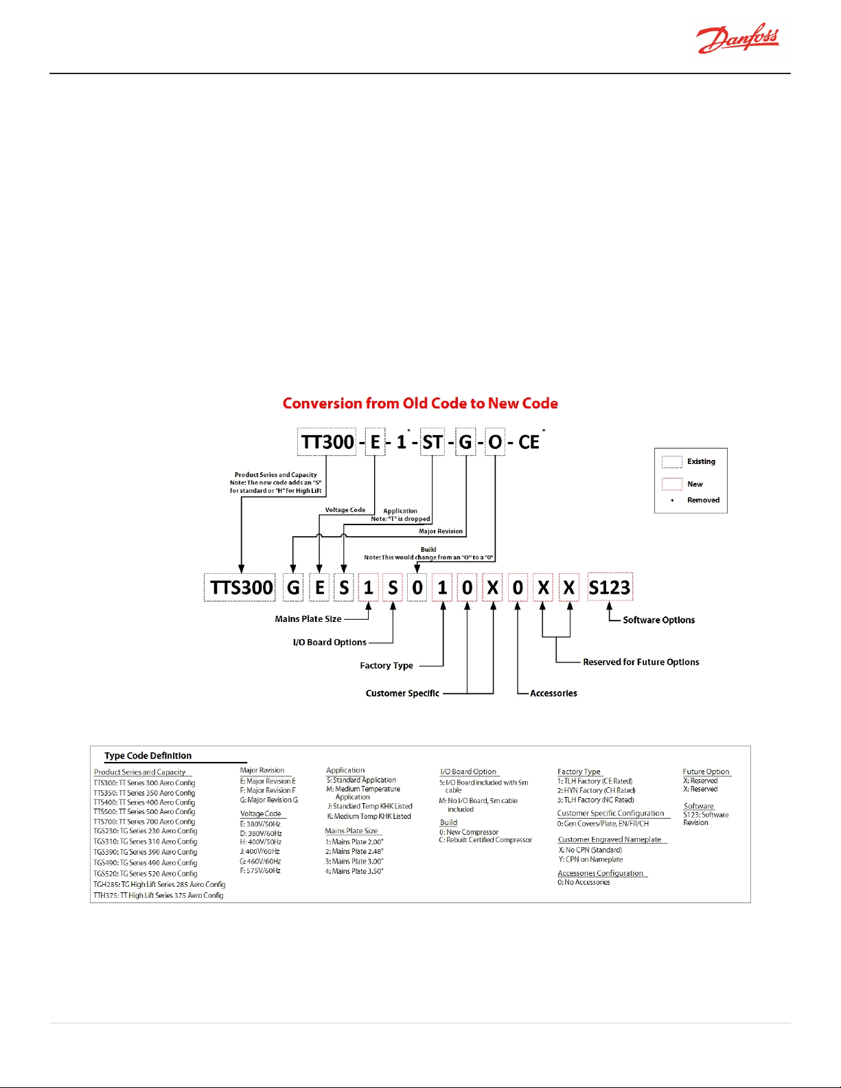
As of May 6, 2019, the product nomenclature changed. Figure 2-1 Old Type Code to New Type Code Rev D maps
the old structure of the Type Code to the new structure. Additionally, the “Series” indicators not have an additional
character in order to differentiate the standard compressors from high-lift compressors. Unless the compressor is a
high-lift design, an “S” will be added (e.g., TTS350). A high lift compressor will have an “H” in the Series designation
(e.g., TTH375). Throughout this manual, it shall be assumed that if a series designation contains neither an "S" or "H"
(e.g., TT350) that it is not a high-lift design. Refer to Figure 2-2 Compressor Nomenclature for a complete
description for the new Type Code.
2.1 TTS/TGS/TTH/TGH Compressor Nomenclature
Figure 2-1 Old Type Code to New Type Code Rev D
M-AP-001-EN Rev. S-9/8/2021 Page 19 of 136
Page 20
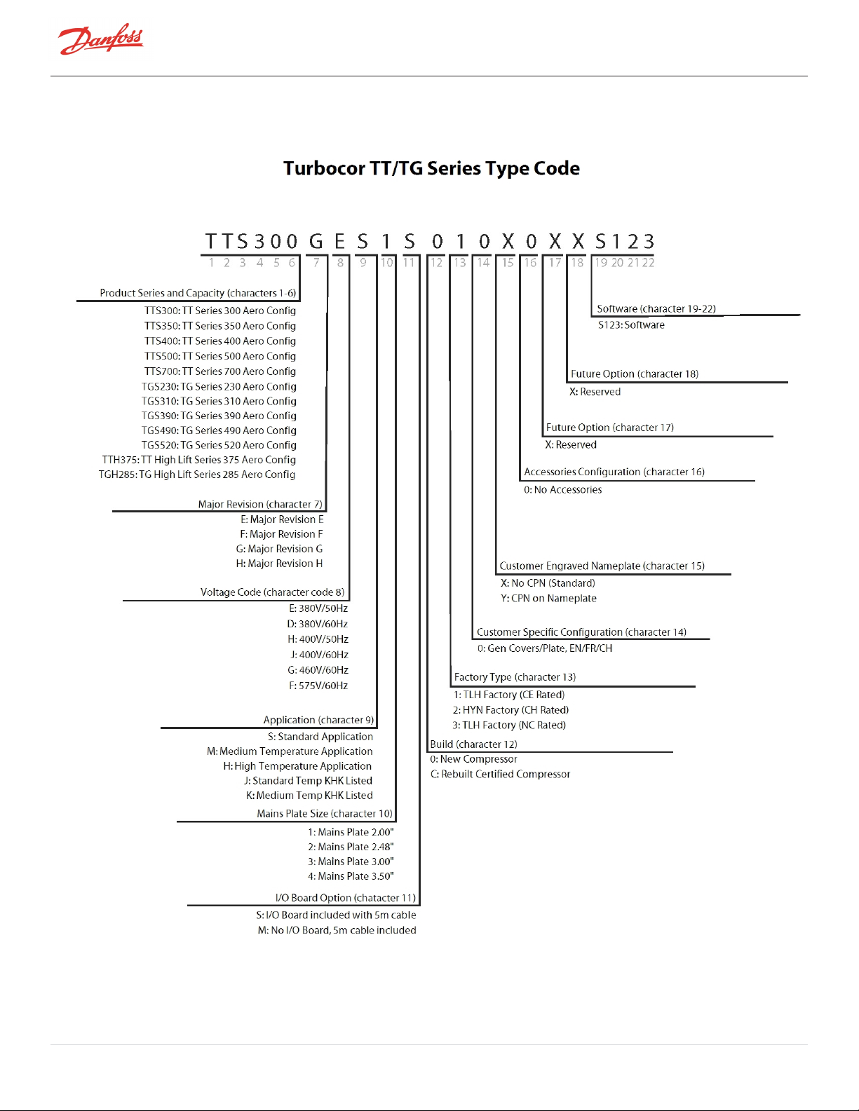
Figure 2-2 Compressor Nomenclature
Page 20 of 136 - M-AP-001-EN Rev. S 9/8/2021
Page 21

2.2 Refrigerant Type
Turbocor compressors are designed to be applied only with specific refrigerants. The ANSI/ASHRAE 34 Standard
(Safety Classification of Refrigerants) classification should be taken into account when designing and applying
Turbocor compressors. We also strongly recommend following the current ANSI/ASHRAE Standard 15 (Safety
Standard for Refrigeration Systems) or other applicable local standards for the mechanical room design and
application of all equipment using Turbocor compressors.
Table 2-1 Refrigerant Used with Turbocor Compressors
Compressor Series Refrigerants ASHRAE/ANSI Standard 34 Classifications
TTS/TTH R134, R513A A1
TGS/TGH R515B, R1234ze(E) A1, A2L
NOTE
l Do not use recycled refrigerant as it may contain oil, which can affect system reliability
l The refrigerant should be pure and stored in virgin containers
l R513A refrigerant is only compatible with EPDM O-rings
NOTE
To ensure a reliable chiller system, all system components, most notably expansion valves, solenoid valves, and sensors, be appropriate for
application in oil-free systems as determined by the component manufacturer. In addition, all chiller system components exposed to
refrigerant should be approved by their manufacturer for use with that refrigerant.
2.3 Environment
The compressor should not be operated at an altitude higher than 3000 m.
The compressor should be stored and operated within the following ambient temperature ranges:
l Storage: -30°C to 70°C (-22°F to 158°F)
l Operation: -1°C to 51°C (30°F to 124°F)
l Mains Power Applied Non Operating Limit: -25°C (-13°F)
l Humidity: 0-95% Non Condensing
• • • CAUTION • • •
Power must be applied to all compressors on the chiller for a minimum of 24 hours prior to starting the compressors.
If a compressor is stored in an ambient condition where the humidity is at or above 85% for an extended amount of
time, the following precautions must be taken prior to giving the compressor a demand (Run) command.
l Prior to powering the compressor/chiller, visually inspect the top-side power electronics to ensure
there are no signs of oxidation or any other signs of moisture or condensation.
l Ensure all covers are in place and secured. The Danfoss Turbocor compressors have integrated seals in
each cover which prevent ingress of moisture and contaminants; however, if the covers are not in place
and properly secured, outside air and contaminates can intrude and potentially affect the electronics.
M-AP-001-EN Rev. S-9/8/2021 Page 21 of 136
Page 22
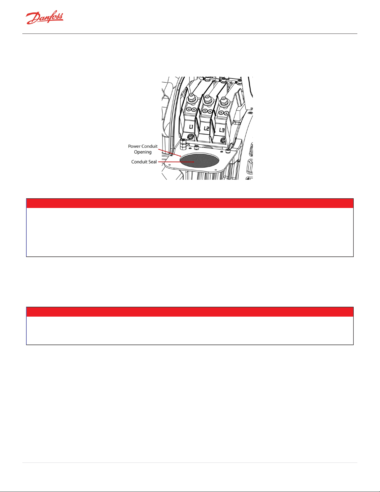
l Seal any open space around the mains power wire and conduit at the mains input plate of the
compressor to prevent ingress of outside air and contaminants that could come from the mains power
cabinet.
Figure 2-3 Mains Plate Sealing
NOTE
l Contact Danfoss LLC Applications for lower ambient temperature operations. Refer to Figure Operating Envelopes. in this
manual for details of the operating conditions. These conditions are in line with the AHRI 540 Standard.
l All compressors/components should be protected from environments that could cause corrosion to exposed metals. For
outdoor installations, a weather-proof enclosure with vents is recommended to house the compressor.
l TTS/TGS/TTH/TGH compressors can operate below -1°C ambient if refrigerant circuit is maintained at a minimum of -1°C
Saturated temperature.
2.4 Configurations of the TTS/TGS/TTH/TGH Compressor Models
The compressor, motor, and power assemblies are packaged in the design.
• • • CAUTION • • •
It is important to take all precautions to avoid refrigerant migration, especially on air-cooled units. If the compressor is filled with liquid,
there is a high risk of bearing damage, thus putting the compressor out of service. The compressor warranty will be voided if the
compressor is damaged due to refrigerant migration.
Page 22 of 136 - M-AP-001-EN Rev. S 9/8/2021
Page 23
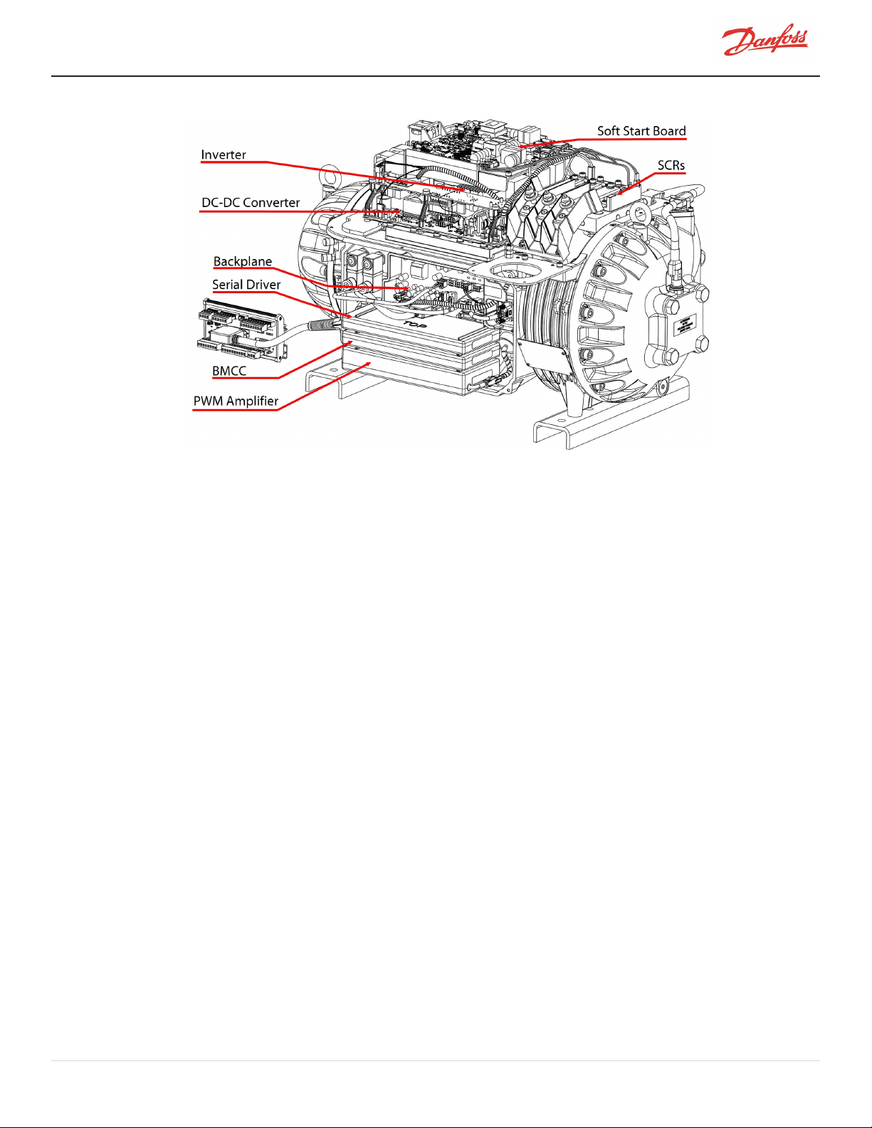
Figure 2-4 Major Components
2.5 Compressor Module
This section provides a brief overview of the Compressor Module.
The Compressor Module is comprised of three portions:
l Aerodynamics - The aerodynamics portion manages the refrigerant compression process from the
suction to the discharge including the inlet guide vane assembly.
l Motor - The motor portion contains a direct-drive, high-efficiency, permanent-magnet synchronous
motor powered by pulse-width-modulating (PWM) voltage supply. The high-speed variable-frequency
operation that affords high-speed efficiency, compactness and soft start capability. Motor cooling is by
liquid refrigerant injection.
l Electronics - The electronics is divided into two (2) sections: Power electronics located on the top of the
compressor including soft-start, DC-DC, Silicon-Controlled Rectifier (SCR), capacitors, and inverter.
Control electronics located on the side of the compressor including: backplane, BMCC, serial driver, and
PWM.
M-AP-001-EN Rev. S-9/8/2021 Page 23 of 136
Page 24

THISPAGEINTENTIONALLYLEFTBLANK
Page 24 of 136 - M-AP-001-EN Rev. S 9/8/2021
Page 25
Chapter 3.0 Functional Description
Compressor operation begins with a call for cooling from a chiller controller. The compressor controller then begins
compressor ramp-up.
3.1 Main Fluid Path
The following paragraphs describe the flow of refrigerant from the intake to the discharge port of the compressor
(refer to Figure 3-1 Compressor Fluid Path TGS230/TTS300 and Figure 3-2 Compressor Fluid Path (TGS310, TTS350,
TGS390, TGS490, TTS400, TGS520, and TTS700).
The refrigerant enters the suction side of the compressor as a low-pressure, low-temperature, superheated gas. The
refrigerant gas passes through a set of adjustable Inlet Guide Vanes (IGVs) that are used to control the compressor
capacity at low-load conditions. The first compression element the gas encounters is the first-stage impeller. The
centrifugal force produced by the rotating impeller results in an increase in both gas velocity and pressure. The
high-velocity gas discharging from the impeller is directed to the second-stage impeller through de-swirl vanes. The
gas is further compressed by the second-stage impeller and then discharged through a volute via a diffuser (a volute
is a curved funnel increasing in area to the discharge port; as the area of the cross-section increases, the volute
reduces the speed of the gas and increases its pressure). From there, the high-pressure/high-temperature gas exits
the compressor at the discharge port.
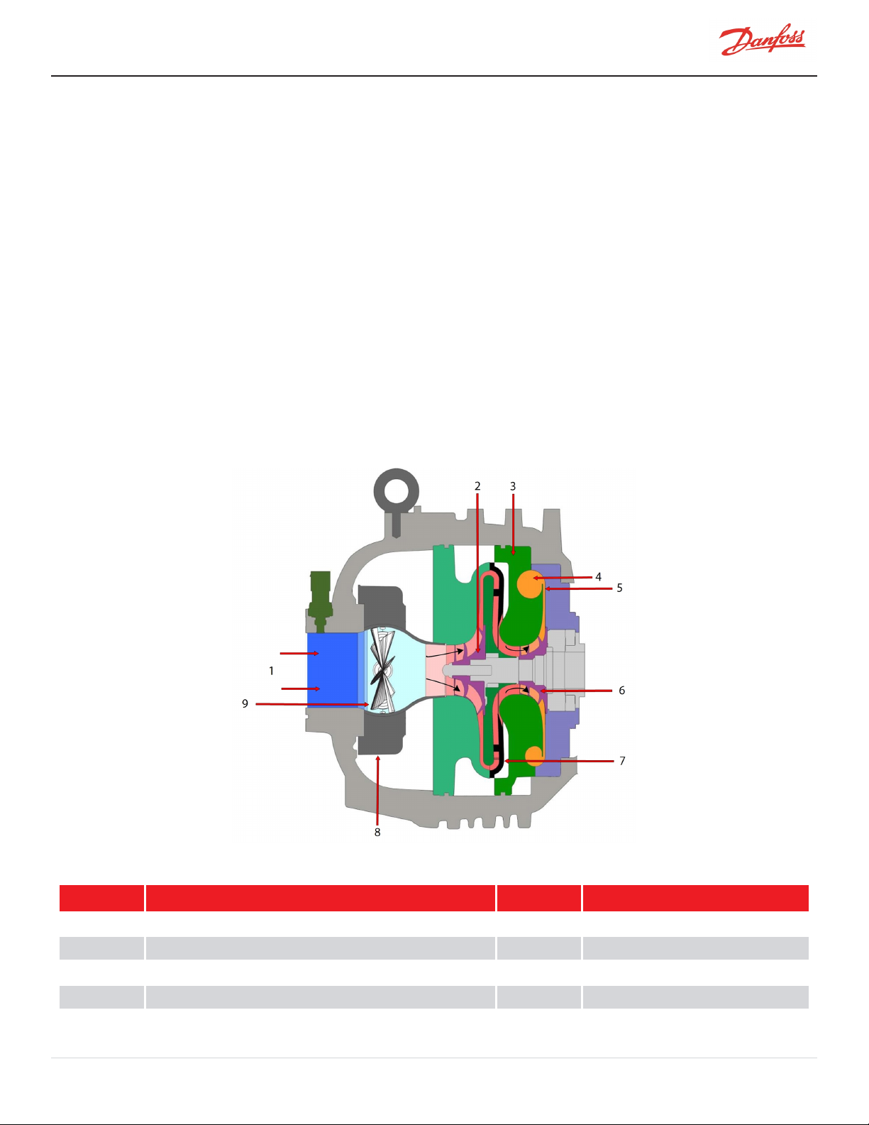
Figure 3-1 Compressor Fluid Path TGS230/TTS300
Table 3-1 Compressor Fluid Path TGS230/TTS300
No. Description No. Description
1 Low-Pressure/Low Temperature Gas 6 Second-Stage Impeller
2 First-Stage Impeller 7 Vaned Diffuser
3 Volute Assembly 8 IGV
4 Discharge Port 9 Vanes
5 High-Pressure/High Temperature Gas
M-AP-001-EN Rev. S-9/8/2021 Page 25 of 136
Page 26
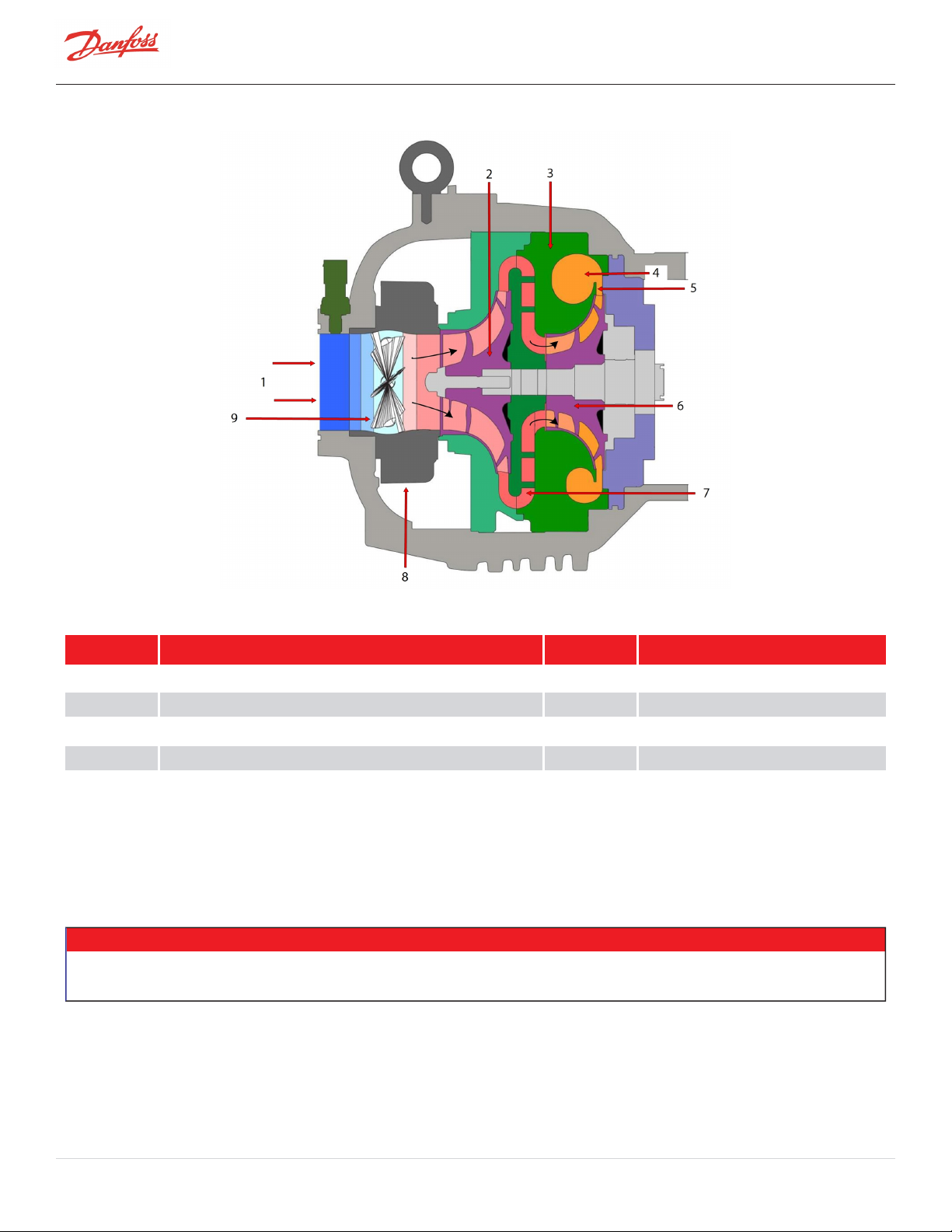
Figure 3-2 Compressor Fluid Path (TGS310, TTS350, TGS390, TGS490, TTS400, TGS520, and TTS700)
Table 3-2 Compressor Fluid Path (TGS310, TTS350, TGS390, TGS490, TTS400, TGS520, and TTS700)
No. Description No. Description
1 Low-Pressure/Low Temperature Gas 6 Second-Stage Impeller
2 First-Stage Impeller 7 Vaneless Diffuser
3 Volute Assembly 8 IGV
4 Discharge Port 9 Vanes
5 High-Pressure/High Temperature Gas
3.2 Motor Cooling
Liquid refrigerant is channeled at full condenser pressure from the main liquid line to the compressor to cool the
electronic, mechanical, and electromechanical components (refer to Figure 3-3 Compressor Cooling Circuit (TGS230
/ TTS300) and Figure 3-4 Compressor Cooling Circuit (TTS300 Split-Cooling, TGS310, TTS350, TGS390, TGS490,
TTS400, TTS700, and TGS520).
• • • CAUTION • • •
A minimum operating pressure ratio of 1.5 is required to maintain adequate cooling of the compressor, unless the system is fitted with an
appropriately selected liquid pump cooling pump.
The sub-cooled refrigerant enters the compressor through two solenoid valves and associated fixed orifices located
behind the service access cover. The orifices cause the refrigerant to expand, thereby lowering its temperature. Both
valves open in response to the temperature sensed in the motor and inverter.
Page 26 of 136 - M-AP-001-EN Rev. S 9/8/2021
Page 27
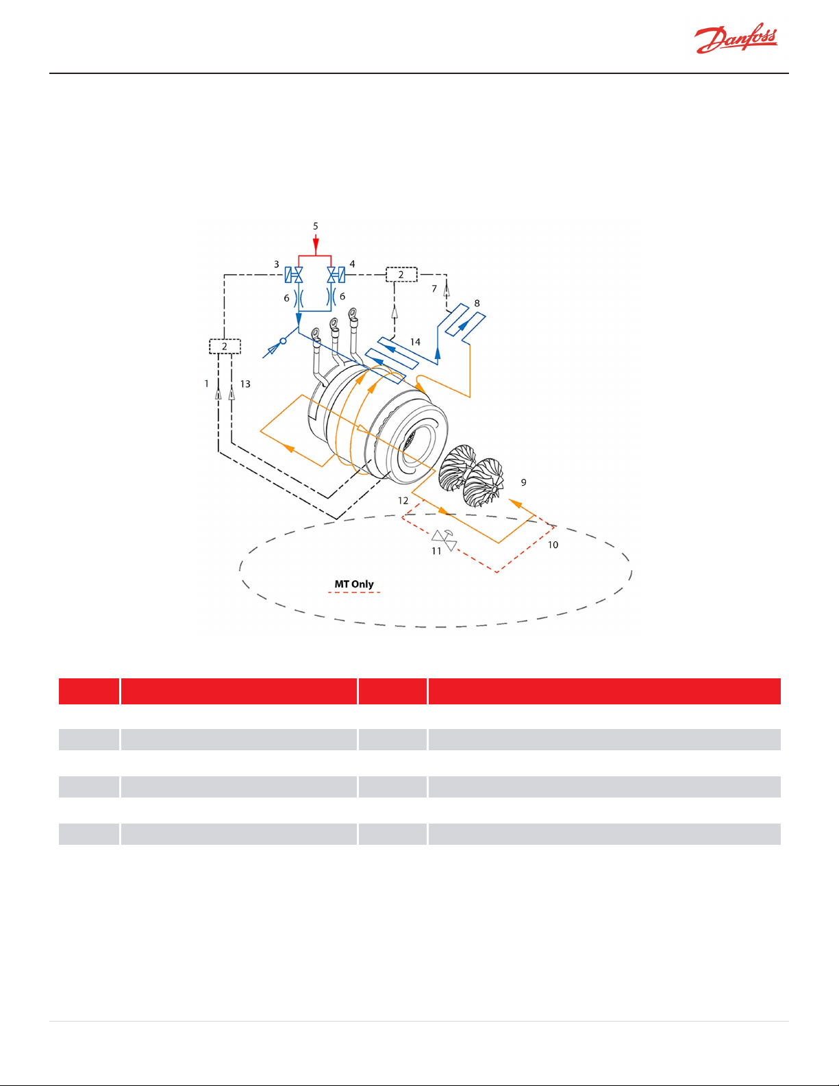
From the outlet of the orifices, the refrigerant is directed to the heatsink plate of the inverter and to the underside of
the SCR heatsink. The refrigerant also passes through grooves surrounding the motor stator. As the refrigerant flows
through the grooves, it vaporizes into a gas. At the coil outlet, the refrigerant gas is channeled back to the suction
inlet via the motor cavity, thereby cooling the rotor. All models with the exception of the TTS300 and TGS230 use a
split-cooling method where the motor and electronics portions are cooled separately by refrigerant liquid.
Figure 3-3 Compressor Cooling Circuit (TGS230 / TTS300)
Table 3-3 Compressor Cooling Circuit (TGS230 / TTS300)
No. Description No. Description
1 From Motor Winding Temp Sensor 8 SCR
2 BMCC 9 Motor/Rotor Cooling Gas and Leakage
3 Solenoid M 10 Cooling path re-enters at the suction line of the chiller
4 Solenoid E 11 Pressure Regulating Valve
5 Liquid Refrigerant Inlet 12 Cooling path redirects outside of the compressor
6 Orifice 13 From Motor Cavity Temp Sensor
7 From Inverter Temp Sensor 14 Inverter
M-AP-001-EN Rev. S-9/8/2021 Page 27 of 136
Page 28
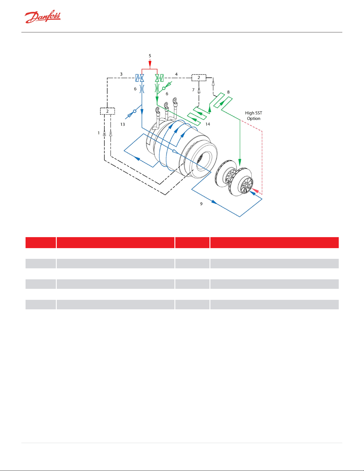
Figure 3-4 Compressor Cooling Circuit (TTS300 Split-Cooling, TGS310, TTS350, TGS390, TGS490, TTS400, TTS700, and TGS520)
Table 3-4 Compressor Cooling Circuit (TTS300 Split-Cooling, TGS310, TTS350, TGS390, TGS490, TTS400, TTS700, and TGS520)
No. Description No. Description
1 From Motor Winding Temp Sensor 7 From Inverter Temp Sensor
2 BMCC 8 SCR
3 Solenoid M 9 Motor/Rotor Cooling Gas and Leakage
4 Solenoid E 10 From Motor Cavity Temp Sensor
5 Liquid Refrigerant Inlet 11 Inverter
6 Orifice
Page 28 of 136 - M-AP-001-EN Rev. S 9/8/2021
Page 29
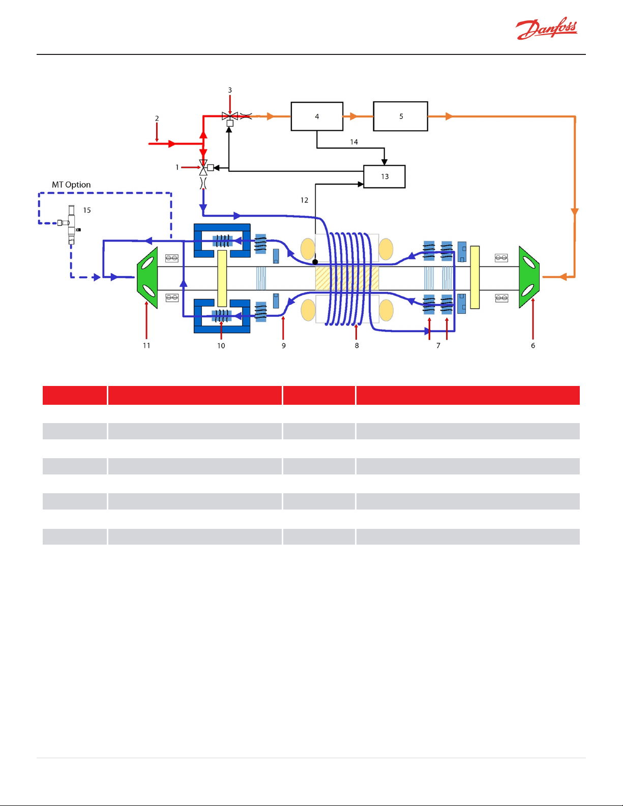
Figure 3-5 Highlift Cooling Circuit Flow Diagram (TGH285/TTH375)
Table 3-5 Highlift Cooling Circuit Flow Diagram (TGH285/TTH375)
No. Description No. Description
1 Solenoid M 9 Radial Bearing
2 Liquid Refrigerant Inlet 10 Axial Bearing
3 Solenoid E 11 Impeller - 1stStage
4 Inverter 12 Motor Cavity Temp. Sensor
5 SCR 13 BMCC
6 Impeller - 2ndStage 14 Inverter Temp Sensor
7 Radial Bearing 15 PRV (pressure regulating valve)
8 Stator/Rotor
3.3 Inlet Guide Vanes
The Inlet Guide Vane (IGV) assembly is a variable-angle guiding device that is used for capacity control. The IGV
assembly consists of movable vanes and a motor. The vane opening is determined by the BMCC and controlled by
the Serial Driver. The IGV position can vary between 0-110% where 0% is fully closed and 110% is fully open with the
vanes at a 90° angle.
M-AP-001-EN Rev. S-9/8/2021 Page 29 of 136
Page 30
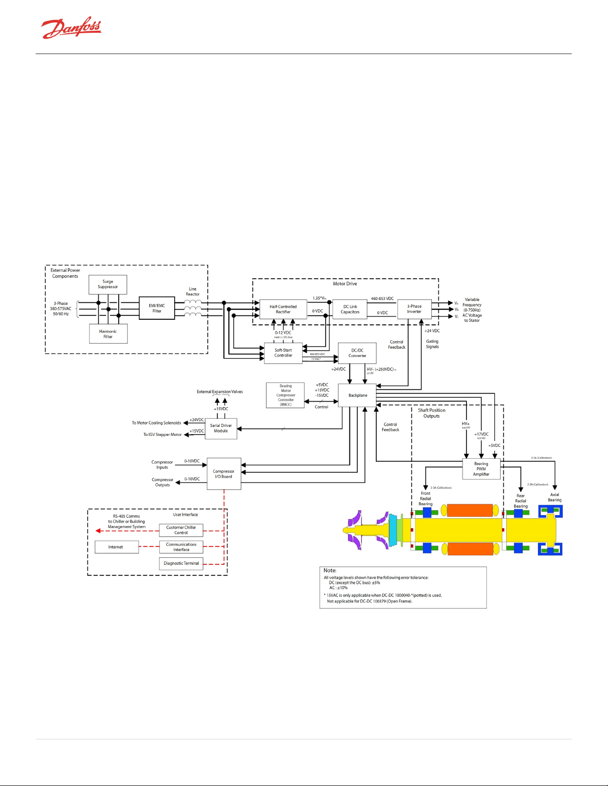
3.4 Compressor Control Overview
Refer to Figure 3-6 Compressor Control System Functional Block Diagram which shows a functional block diagram of
the compressor control and monitoring system. Refer to Figure 3-8 Magnetic Bearing Control System which displays
the component locations. The major components include:
l Motor Drive
l Soft-Start Board
l BMCC
l Bearing PWM Amplifier
l Backplane
l Serial Driver
l HV DC-DC Converter
Figure 3-6 Compressor Control System Functional Block Diagram
3.4.1 Motor Drive System
Normally, AC power to the compressor remains on even when the compressor is in the idle state. The compressor
motor requires a variable-frequency three-phase source for variable-speed operation. The AC line voltage is
converted into a DC voltage by SCRs. DC capacitors at the SCR output serve as energy storage and filter out the
Page 30 of 136 - M-AP-001-EN Rev. S 9/8/2021
Page 31

voltage ripple to provide a smooth DC voltage. The inverter that converts the DC voltage into an adjustable three-
phase AC voltage. PWM signals from the BMCC control the inverter output frequency and voltage. By modulating
the on and off times of the inverter power switches, three-phase variable sinusoidal waveforms are obtained.
If the power should fail while the compressor is running, the motor switches into generator mode, thereby
sustaining the capacitor charge. The rotor can then spin down safely in a controlled sequence preventing damage to
components.
NOTE
The variable frequency drive (VFD) or inverter, supplied as standard with all Turbocor compressors, is mechanically, electrically, and
logically integrated with the operation of the compressor and its supporting magnetic bearing system. One of the most critical functions
handled by this tight integration is the regenerative power feature which extracts power from the spinning rotor to ensure that the
magnetic bearing system is fully functional during a power loss event. Because of the close integration between the compressor and the
VFD, Danfoss LLC cannot support the use of non-integrated VFDs due to the extensive development required to ensure the same
functionality and reliability as the standard integrated VFD.
3.4.2 Soft Start
The Soft Start limits inrush current by progressively increasing the conduction angle of the SCRs. This technique is
used at compressor start-up while the DC capacitors are charging up. The Soft Start function and the variable-speed
drive combined limit the inrush current at startup.
3.4.3 Bearing Motor Compressor Controller
The hardware and software for the compressor controller and the bearing/motor controller physically reside in the
BMCC. The BMCC is the central processor of the compressor.
3.4.4 Compressor Control
The Compressor Controller is continuously updated with critical data from external sensors that indicate the
compressor’s operating status. Under program control, the compressor controller can respond to changing
conditions and requirements to ensure optimum system performance.
3.4.5 Capacity Control
One of the Compressor Controller’s primary functions is to control the compressor’s motor speed and IGV position in
order to satisfy load requirements and to avoid surge and choke conditions. However, the majority of capacity
control can be achieved via motor speed.
3.4.6 Expansion Valve Control
The onboard Electronic Expansion Valve (EXV) driver uses manual control only. Depending on the application, a load
balancing (hot gas bypass) valve can be manually driven by the auxiliary EXV output. Load balancing allows the
compressor to obtain lower capacities at higher pressure ratios. The valve opens to lower the overall pressure ratio
and thereby reduces the lift, enabling the compressor to reduce speed/unload.
3.4.7 Motor/Bearing Control
The magnetic bearing system physically supports a rotating shaft while enabling non-contact between the shaft and
surrounding stationary surfaces. A digital bearing controller and motor controller provide the PWM command
signals to the Bearing PWM Amplifier and Inverter, respectively. The bearing controller also collects shaft position
inputs from sensors and uses the feedback to calculate and maintain the desired shaft position.
M-AP-001-EN Rev. S-9/8/2021 Page 31 of 136
Page 32

3.4.8 Monitoring Functions
The Compressor Controller monitors more than 60 parameters, including:
l Gas pressure and temperature monitoring
l Line voltage monitoring and phase failure detection
l Motor temperature
l Line currents
l External interlock
3.4.9 Abnormal Conditions
The Compressor Controller responds to abnormal conditions by monitoring:
l Surge RPMs
l Choke RPMs
l Power failure/phase unbalance
l Low/high ambient temperature
l High discharge pressure
l Low suction pressure
l Motor-cooling circuit failure (over temperature)
l Refrigerant loss
l Power supply
l Overcurrent
3.4.10 Bearing PWM Amplifier
The Bearing PWM Amplifier supplies current to the radial and axial magnetic bearing actuators. The PWM Amplifier
consists of high-voltage switches that are turned on and off at a high frequency, as commanded by the PWM signal
from the BMCC.
3.4.11 Serial Driver
The Serial Driver module performs serial-to-parallel conversion on the stepper motor drive signals from the BMCC.
The module also contains four normally open relays under BMCC control. Two of the relays drive the motor-cooling
solenoids, and the other two are used to indicate compressor fault status and running status. The status relays can
be wired to external control circuits.
3.4.12 Backplane
The Backplane physically interconnects the onboard plug-in modules with the power electronics, IGV stepper motor,
motor-cooling solenoids, rotor position sensors, and pressure/temperature sensors.
The Backplane also features onboard, low-voltage DC-DC converters for generating +15V, -15V, +5V, and +17V from
an input of +24VDC. The Backplane receives its +24VDC power input from the High-Voltage (HV) DC-DC Converter
mounted on the topside of the compressor.
The Backplane is also equipped with status-indicating Light-Emitting Diodes (LEDs). All LEDs are yellow except for
the alarm LED, which is green/red. Table 3-6 Backplane LEDs describes the LEDs functions.
Page 32 of 136 - M-AP-001-EN Rev. S 9/8/2021
Page 33
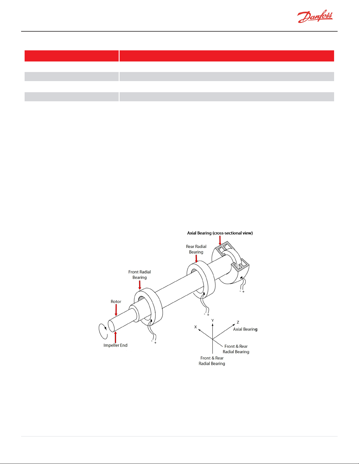
Table 3-6 Backplane LEDs
LED Function
+5V, +15V, +17HV, +24V LEDs are lighted when DC power is available.
Cool-H, Cool-L LEDs are lighted when their respective coil is energized.
Run LED is lighted when the shaft is spinning.
Alarm LED is green when in normal status, red when in alarm status.
D13, D14, D15, D16 LEDs indicate IGV status and flash when IGV is moving.
3.4.13 High-Voltage DC-DC Converter
DC-DC converters supply and electrically isolate the high and low DC voltages that are required by the control
circuits. The HV DC-DC Converter delivers 24VDC and 250VDC from an input of 460-900VDC. The 24VDC and
250VDC are used to power the Backplane and magnetic bearing PWM Amplifier, respectively.
3.5 Magnetic Bearing System
3.5.1 Overview
A rotating shaft, under changing load conditions, will experience forces in both radial and axial directions. In order
to compensate for these forces, a five-axis bearing system is used, incorporating two radial bearings of two axes
each, and one thrust (axial) bearing. Refer to Figure 3-7 Magnetic Bearing Configuration
Figure 3-7 Magnetic Bearing Configuration
3.5.2 Bearing Control System
The Bearing Control System uses rotor position feedback to close the loop and maintain the rotor in the correct
running position (refer to Figure 3-8 Magnetic Bearing Control System). The Bearing Controller issues position
commands to the Bearing PWM Amplifier. The position commands consist of five channels with each channel
M-AP-001-EN Rev. S-9/8/2021 Page 33 of 136
Page 34
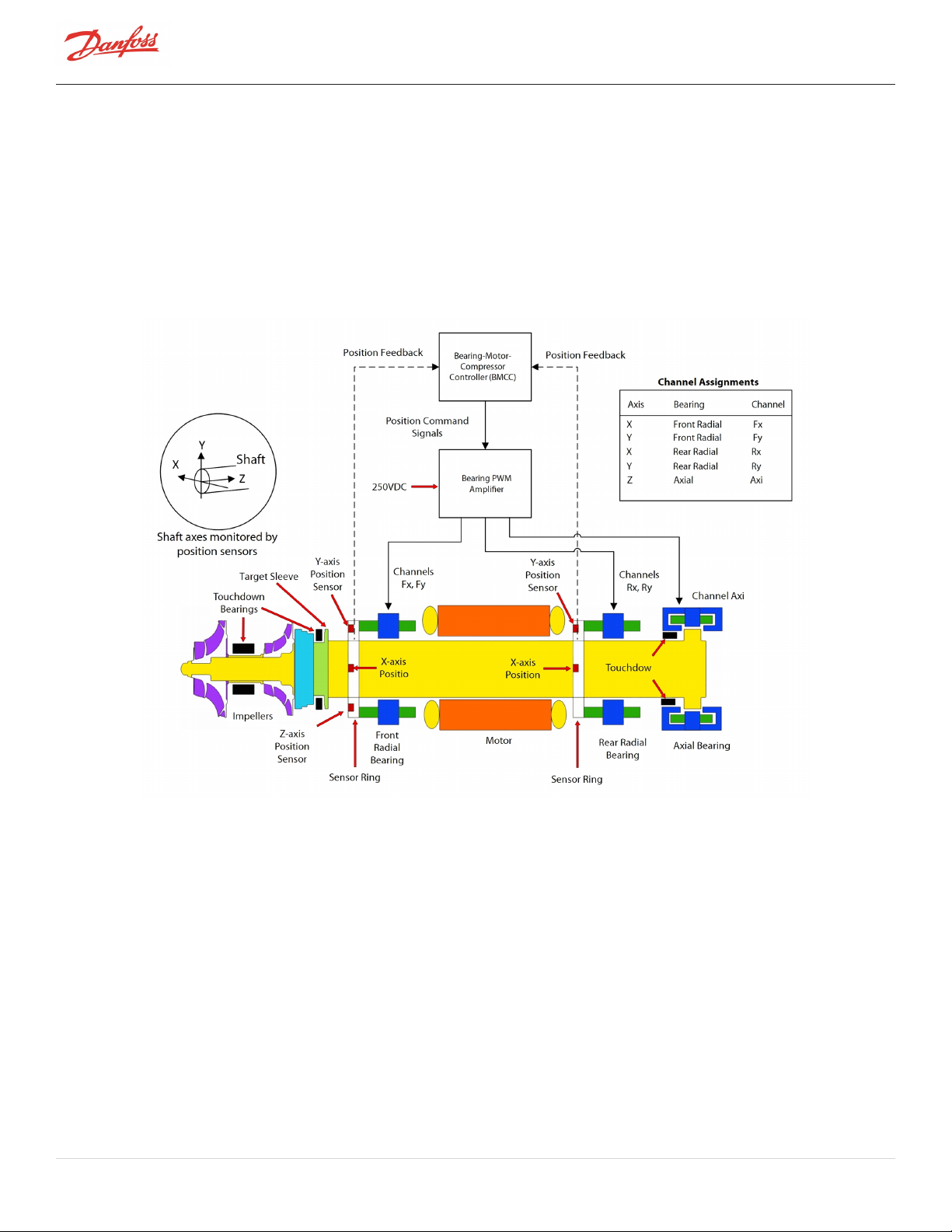
allocated to one of the five bearing actuator coils (one coil for each axis). The amplifier uses Inverter technology to
convert the low-voltage position commands to the 250VDC PWM signals that are applied to each bearing actuator
coil.
Rotor position sensors are located on rings attached to the front and rear radial bearing assemblies. The front sensor
ring contains sensors that read the rotor position along the X, Y, and Z axes. The rotor position along the Z (or axial)
axis is read by measuring the distance between the sensor and a target sleeve mounted on the rotor. The rear
sensor ring contains sensors that read the position along the X and Y axes. Information from the position sensors is
continuously fed back to the bearing controller.
Figure 3-8 Magnetic Bearing Control System
Page 34 of 136 - M-AP-001-EN Rev. S 9/8/2021
Page 35
Chapter 4.0 Control Interface Wiring
The Compressor I/O Board is the entry point for control wiring from the chiller/plant to the compressor. Refer to
Figure 4-1 Typical Control Wiring. Figure 4-2 Modbus Grounding Diagram for the proper Compressor I/O Board
connectivity.
Figure 4-1 Typical Control Wiring
M-AP-001-EN Rev. S-9/8/2021 Page 35 of 136
Page 36
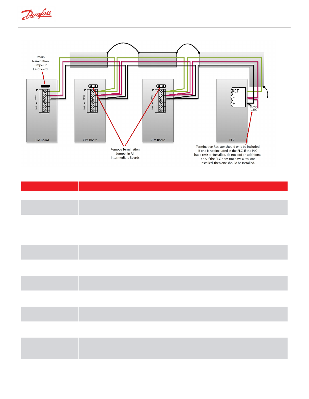
Figure 4-2 Modbus Grounding Diagram
Table 4-1 Control Wiring Details
I/O Description
COM (shield) Shield for RS-485 communication.
Modbus RS-485
NetB/NetA
Stepper Motor 1 Phase
1A, 1B, 2A, 2B, and
Stepper Motor 2 Phase
1A, 1B, 2A, 2B
Level Sensor +15V
(Evaporator)
Sensor Signal
(Evaporator)
Level Sensor +15V
(Economizer)
Sensor Signal
(Economizer)
Demand 0 - 10V Analog input from customer-supplied controller to drive the compressor, i.e., 0 - max. kW input with a
Interlock Connects to a set of external normally closed contacts that typically open in the event of loss of chilled
Modbus over RS-485 communication port.
Optional output connections for controlling the main electronic expansion valve (evaporator) or auxiliary
electronic expansion valve (economizer or load balancing valve). 200ma Maximum output on each driver.
Valve frequency will effect operational characteristics.
Power supply for level sensor #1.
Input from a level sensor to control the main expansion valve (evaporator).
Power supply for level sensor #2.
Input from a level sensor to control the auxiliary expansion valve (economizer).
deadband of 2VDC for the respective compressor model. Only available in 3.1.4; removed in 4.x forward.
water or air flow. Typically a 1.5VDC Output signal. NOTE: This is not a safety certified interlock.
Status An internal normally open contact that is closed during normal operation and opens in the event of a
compressor fault. With the circuit open, the compressor will not restart until the demand signal has been
reset to 0 (via chiller/unit controller). Circuit rated at 1A @ 30VDC/24VAC or .03A @ 120VAC.
Liquid Temperature Optional input for monitoring temperature. The temperature sensor must be an NTC type 10K @ 25°C
Page 36 of 136 - M-AP-001-EN Rev. S 9/8/2021
Page 37

I/O Description
thermistor.
Run An internal N/O contact that is closed while the compressor is running. The speed at which the contact
closes is user-configurable via the monitor program. Circuit rated at 1A @ 30VDC/24VAC or 0.3A @
120VAC.
Analog Universal analog output manually controlled as a percentage of total voltage written through Modbus.
This can be configured for 0-5V or 0-10V via on board jumpers.
Entering Chilled Water
Temp
Leaving Chilled Water
Temp
Spare T +/- Optional input for monitoring temperature. The temperature sensor must be an NTC type 10K @ 25°C
Spare P +/- Can be connected to a 0-5V type pressure sensor.
Table 4-2 Jumper Details
Analog input indicating water temperature. The temperature sensor must be an NTC type 10K @ 25°C
thermistor. Refer to the Service Manual for thermistor specification.
Analog input indicating water temperature. The temperature sensor must be an NTC type 10K @ 25°C
thermistor. Refer to the Service Manual for thermistor specification.
thermistor.
Jumper Function and Setup
JP1 Determines the operating voltage range (0-5V or 0-10V) of the ANALOG output. If used, set the jumper to the
appropriate range.
JP2 Modbus termination jumper: install the jumper if Modbus is used and if the Modbus connection is at the end of a run.
ENTRY Install the jumper if there is no temperature sensor connected to the “Entering Chilled Water” analog input.
LEAVE Install the jumper if there is no temperature sensor connected to the “Leaving Chilled Water” analog input.
JP5/JP6 Jumpers J5 and J6 are used to match the characteristics of the liquid level sensors.
Voltage-type Level Sensor - If using a voltage-type sensor with 15V supply and 0-5V signal, install jumpers between
LVL pins 2a and 3a, and pins 2b and 3b. Connect the sensor leads to the +, S, and - terminals on the Interface module.
Consult vendor documentation for sensor lead identification.
Resistive-type Float Sensor - If using a resistive-type sensor, install jumpers between LVL pins 1a and 2a, and pins 1b
and 2b. Connect the sensor leads to the - and S terminals on the Interface module.
JP7 Supplies 5VDC to pin 1 on the 9-pin connector to power an optional Bluetooth adapter. Install if Bluetooth device is
being used in RS-232 connection (DB9).
*NO LONGER APPLIES*
4.1 Control Wiring Connection Guidelines
To ensure proper control wiring techniques, follow these guidelines:
1. The ground reference of the external circuit connected to the Compressor I/O Board must be at the
same potential as the ground reference on the Compressor I/O Board.
2. The Interlock circuit should be voltage-free. For instance, all external contractors/switches must not
introduce current into the circuit.
3. Analog outputs (such as Motor Speed) must be received by the external circuit without sending current
back to the Compressor I/O Board.
M-AP-001-EN Rev. S-9/8/2021 Page 37 of 136
Page 38
4. All interlock and analog output cables should be shielded with one end of the shield connected to the
common analog or digital ground bus. The other end of the shield must not be grounded as this would
create a ground loop. Refer to Figure 4-2 Modbus Grounding Diagram.
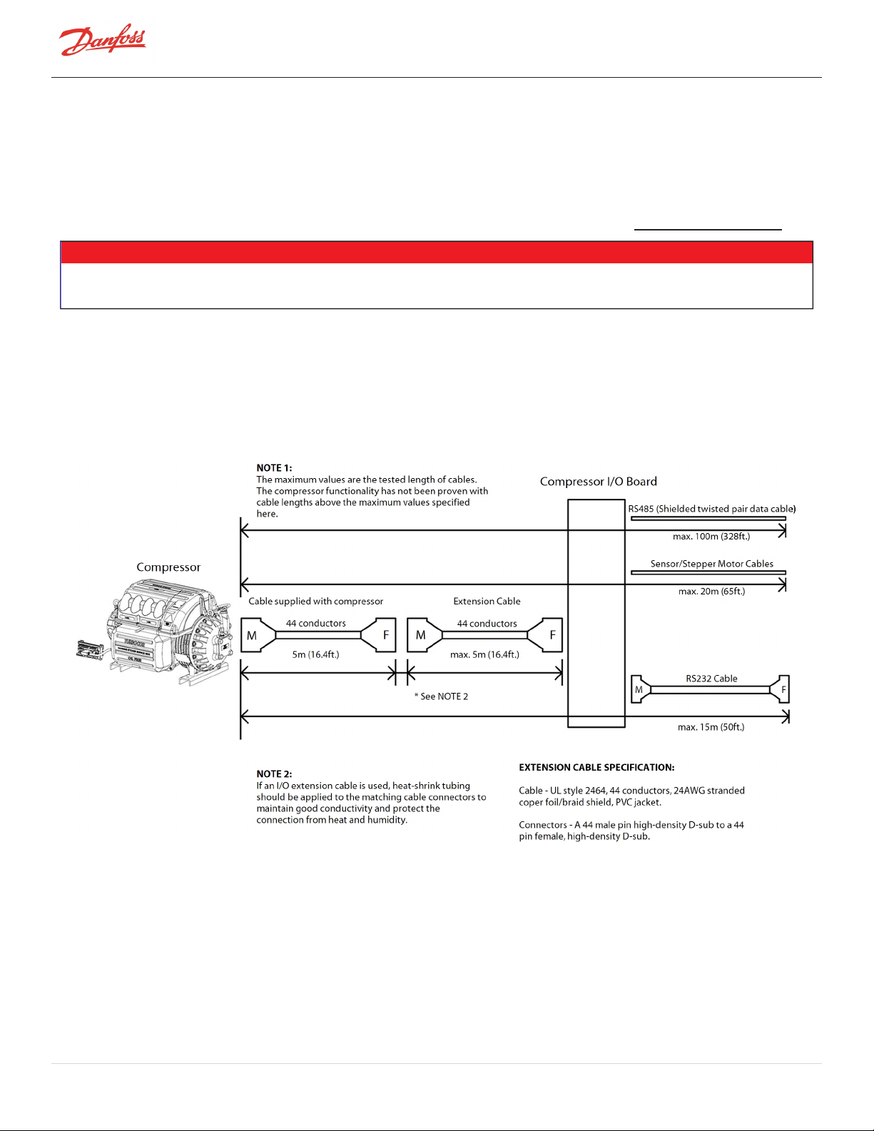
4.2 Interface Cable
The cable that carries the I/O communication to the compressor is 5 meters (16.4 feet) in length and is equipped
with high-density 44-pin connectors (female at one end and male at the other end). An extension cable is available
from your local supplier. An optional 10 meter (32.8 ft) cable is also available in the Spare Parts Selection Guide.
NOTE
If an I/O extension cable is used, heat-shrink tubing should be applied to the mating cable connectors to maintain good conductivity and
protect the connection from heat and humidity.
For RS-485 communication, the maximum cable length should not exceed 100 meters (328 feet). If using RS-232
communication, the cable length should not exceed 15 meters (50 feet) between the PC and the compressor (refer
to Figure 4-3 I/OWiring Specifications.)
Figure 4-3 I/OWiring Specifications
Page 38 of 136 - M-AP-001-EN Rev. S 9/8/2021
Page 39

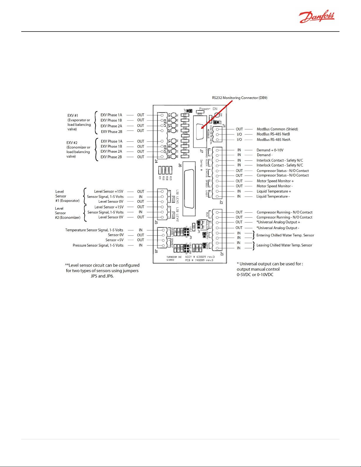
4.3 Compressor I/O Board Mounting Details
The Compressor I/O Board ( Figure 4-4 Compressor I/O Board) must be installed in a Underwriters Laboratories (UL)
approved electrical enclosure equipped with DIN EN 50022, 50035, or 50045 mounting rails. The board should be
mounted in a dry area, free from vibration and electrical noise.
NOTE
The UL listed enclosure should protect against moisture and other corrosive elements.
Figure 4-4 Compressor I/O Board
4.3.1 Compressor I/O Board Mounting Instructions
1. Tilt the I/O Board as shown in Figure 4-5 Compressor I/O Board Installation in order to engage it into
the DIN Rail.
2. Lower the I/O Board until it snaps into place.
Figure 4-5 Compressor I/O Board Installation
M-AP-001-EN Rev. S-9/8/2021 Page 39 of 136
Page 40

THISPAGEINTENTIONALLYLEFTBLANK
Page 40 of 136 - M-AP-001-EN Rev. S 9/8/2021
Page 41

Chapter 5.0 General Specifications
5.1 Construction
l Compressor - Semi-hermetic design
l Main Housing - Dimensionally-stabilized aluminum
l Covers - High-impact, UV stabilized, flame-resistant polymer (TGS series is identified by green cover)
l Shaft - High-strength alloy
l Impellers - High-strength aluminum
l Motor - Permanent magnet, synchronous, DC
l Bearings - Integrated, digitally-controlled, magnetic
l Compressor Control - Integrated, digital capacity control
l Enclosure - IP54 rating
5.2 Maximum Pressure
The maximum pressure that the compressor can operate is regulated directly by two control settings: (1) Alarm Limit
and (2) Fault Limit. It is also controlled by a Pressure Ratio alarm limit monitoring the ratio between the Discharge
and Suction Pressures.
Table 5-1 Discharge Pressure Alarm and Fault Settings
Model
Alarm Fault
kPa(g) PSIG kPa(g)2 PSIG3
TGS230ST* 1239 180 1299 188
TGS230MT* 1116 162 1176 171
TGS310 1240 180 1300 189
TGS490 1240 180 1300 189
TGS390 876 127 926 134
TGS520 876 127 926 134
TGH285 1510 218 1586 229
TTS300ST* 1190 173 1240 180
TTS300MT* 1190 173 1240 180
TTS350 1730 251 1800 261
TTS400 1190 173 1240 180
TTS700 1190 173 1240 180
TTH375 2016 292 2116 306
* In the TGS230/TTS300 compressors, the alarm and fault settings default to lower values of operation, which are
typically deemed appropriate for Water-Cooled conditions. These values allow for adjustment for compressors
placed in Air-Cooled applications, which can have the value increased up to 1730 kPa(g)/250 PSIG for the Alarm and
1800 kPa(g)/260 PSIG for the Fault.
5.3 Maximum Discharge Temperature
The maximum temperature that the compressor can operate is regulated directly by the Fault Limit.
The Maximum Discharge Temperature Limits are defined in Table 5-2 Discharge Temperature Fault Settings.
M-AP-001-EN Rev. S-9/8/2021 Page 41 of 136
Page 42

Table 5-2 Discharge Temperature Fault Settings
Unit Compressor TGS230ST TGS230MT TGS310 TGS490 TGS390 TGS520 TGH285 TTS300ST TTS300MT TTS350 TTS400 TTS700 TTH375
°F Fault 212 194 203 203 194 194 212 121 194 203 194 194 212
°C Fault 100 90 95 95 90 90 100 100 90 95 90 90 100
NOTE
While the values here are represented in Gauge Pressure, the values in the registers will be defined in Absolute Pressure. Refer to the OEM
Programming Manual to identify the specific registers associated with the Discharge Pressure Alarm and Discharge Pressure Fault Limits.
The compressor will also adjust its operation if the pressure ratio exceeds the alarm limit. The Pressure Ratio alarm
limit is defined in Table 5-3 Maximum Pressure Ratio Limits.
Table 5-3 Maximum Pressure Ratio Limits
TGS230ST* TGS230MT* TGS310 TGS490 TGS390 TGS520 TGH285 TTS300ST* TTS300MT* TTS350 TTS400 TTS700 TTH375
Alarm 4 4 5.2 5.2 3.5 3.5 6.3 4 4 5.2 3.5 3.5 6.3
Fault 5.2 5.2 5.5 5.5 4 4 6.5 5.2 5.2 5.5 4 4 6.5
*The TGS230/TTS300 compressor allows for adjustment of this setting. Compressors which are placed in Air-Cooled
applications can have this value increased up to 4.8.
NOTE
Pressure ratio must be calculated using absolute pressures. Refer to the OEM Programming Manual to identify the specific register
associated with the Pressure Ratio Alarm Limit.
Beyond these control limits, the Maximum Design High-Side Pressure for the compressor is shown in Table 5-4
Maximum Allowable Pressure [PS].
Table 5-4 Maximum Allowable Pressure [PS]
Unit All TTS &TGS Compressors TTH/TGHCompressors
kPag 2070 2303
psig 300 334
5.4 Suction Pressure Limits
The Suction Pressure Alarm and Fault Limits are displayed in the Table 5-5 Suction Pressure Alarm and Fault
Settings.
Page 42 of 136 - M-AP-001-EN Rev. S 9/8/2021
Page 43

Table 5-5 Suction Pressure Alarm and Fault Settings
Model
Alarm Fault
kPa(g) PSIG kPa(g) PSIG
TGS230ST 99 14 79 11
TGS230MT 40 6 29 4
TGS310 99 14 79 11
TGS390 99 14 96 14
TGS490 99 14 79 11
TGS520 99 14 96 14
TGH285ST 99 14 79 11
TGH285MT 5 0.73 -4 -0.6
TTS300ST 177 26 152 22
TTS300MT 91 13 76 11
TTS350 177 26 152 22
TTS400 177 26 166 24
TTS700 177 26 166 24
TTH375ST 177 26 152 22
TH375MT 43 6.3 32 4.6
NOTE
Pressure ratio is the ratio of absolute discharge to absolute suction pressure. It can be calculated as follows:
l (DP + 101) / (SP + 101) (kPa) OR
l (DP + 14.7) / (SP + 14.7) (psi)
All TTS/TGS/TTH/TGH Series Turbocor compressors were designed for use in stationary building applications and are
suitable for some marine applications (e.g., cruise ships, floating platforms). Danfoss Turbocor compressors are
produced for civilian use and are not intended for safety critical systems. Misapplication of a Turbocor compressor
will not be covered under Danfoss LLC’s Standard Warranty Terms and Conditions.
5.5 Standards Compliance
It is the responsibility of the Original Equipment Manufacturer (OEM) to ensure that proper safety protocols are in
place and that the chiller system has been designed in a manner that is compliant with all applicable local, national,
and international codes and regulatory requirements governing the use of refrigerants, pressure, vessels, and
electrical power. OEMs must also ensure compliance with the requirements stated in the refrigerant manufacturer’s
Material Safety Data Sheet (MSDS) and that other system components are compatible with the refrigerant, giving
special attention to elastomers and seals.
M-AP-001-EN Rev. S-9/8/2021 Page 43 of 136
Page 44

THISPAGEINTENTIONALLYLEFTBLANK
Page 44 of 136 - M-AP-001-EN Rev. S 9/8/2021
Page 45

Chapter 6.0 Electrical Specifications
6.1 Supply Voltage and Frequency
Turbocor compressors are designed to operate with a power supply that is within an acceptable tolerance for each
nominally rated voltage and frequency. The tables below specify the acceptable supply voltage and frequency
ranges. Using a supply voltage/frequency at or beyond the range limit will cause the compressor to shut down.
Table 6-1 Acceptable AC Voltage Range
Nominal Voltage Acceptable Voltage Range
380V 342 - 418 VAC
400V 360 - 440 VAC
460V 414 - 506 VAC
575V 518 - 635 VAC
6.2 Voltage Sag Immunity
Danfoss TTS/TGS Series Turbocor Compressors comply with SEMI F47-0706 and have been certified by a 3rd party
testing agency tested in accordance with IEC 61000-4-34. Turbocor compressors meet the criteria of SEMI F47 based
on 7.8.2 section (c) which allows for equipment that is a subsystem and/or component to pass by recovery without
operator interface. In the event of a compressor fault, Turbocor compressors are able to be reset/run remotely via
the OEMs' chiller controllers upon clearing of any active fault.
• • • CAUTION • • •
Application of a compressor to any voltage which is outside of the nominal rated voltage defined on the compressor nameplate will result
in voiding of the compressor warranty from Danfoss LLC, unless otherwise stated by Danfoss LLC. This includes any application of a 400V
compressor in a 380V application without the use of a transformer to correct the voltage going into the compressor.
NOTE
Refer to the TTS/TGS Compressor Nomenclature section of this manual for details on the compressor voltage availability.
Table 6-2 Acceptable Frequency Range
Nominal Frequency Acceptable Frequency Range
50Hz 50Hz ±5% (47Hz-53Hz)
60Hz 60Hz ±5% (57Hz-63Hz)
6.3 Compressor Current Limit and Operating Range Settings
The new compressor controller (version 3.0.0 and above; Table 1-1 Application Manual Applicability Scope) is
designed to allow a user to configure the current setting based on the intended application. The compressor defines
the Full Load Ampere (FLA) and Locked Rotor Ampere (LRA) as a range on the nameplate. The settings for the FLA
and LRA are adjustable using the Service Monitoring Tool (SMT) or directly from the customer controller application.
The 3-Phase Over Current Alarm FLA cannot be set higher than the 3-Phase Over-Current Fault limit LRA. The
maximum fault limit and alarm limit settings are dependent upon the Voltage and Model. The Model type defines
the range for the FLA and LRA values.
M-AP-001-EN Rev. S-9/8/2021 Page 45 of 136
Page 46

Table 6-3 FLA and LRA Value Range
Model Voltage
FLA LRA Default
Min Max* Min Max FLA LRA
TGS230 380V 40 106 44 117 40 44
TGS230 400V 40 106 44 117 40 44
TGS230 460V 40 99 44 110 40 44
TGS230 575V 40 79 44 88 40 44
TGS310 380V 50 150 55 165 50 55
TGS310 400V 50 150 55 165 50 55
TGS310 460V 50 135 55 145 50 55
TGS310 575V 50 105 55 116 50 55
TGS390 380V 50 123 55 137 50 55
TGS390 400V 50 123 55 137 50 55
TGS390 460V 50 108 55 120 50 55
TGS390 575V 50 86 55 96 50 55
TGS490 380V 50 210 55 231 50 55
TGS490 400V 50 210 55 231 50 55
TGS490 460V 50 180 55 198 50 55
TGS520 380V 50 149 55 165 50 55
TGS520 400V 50 142 55 158 50 55
TGS520 460V 50 123 55 137 50 55
TGS520 575V 50 99 55 110 50 55
TGH285 380V 50 150 55 165 50 55
TGH285 400V 50 150 55 165 50 55
TGH285 460V 50 131 55 145 50 55
TGH285 575V 50 105 55 116 50 55
TTS300 380V 40 145 44 160 40 44
TTS300 400V 40 145 44 160 40 44
TTS300 460V 40 135 44 150 40 44
TTS300 575V 40 110 44 121 40 44
TTS350 380V 50 210 55 231 50 55
TTS350 400V 50 210 55 231 50 55
TTS350 460V 50 180 55 198 50 55
TTS350 575V 50 144 55 159 50 55
TTS400 380V 60 170 66 187 60 66
TTS400 400V 60 170 66 187 60 66
TTS400 460V 60 150 66 165 60 66
Page 46 of 136 - M-AP-001-EN Rev. S 9/8/2021
Page 47

Model Voltage
FLA LRA Default
Min Max* Min Max FLA LRA
TTS400 575V 60 120 66 132 60 66
TTS700 380V 60 206 66 227 60 66
TTS700 400V 60 196 66 216 60 66
TTS700 460V 60 170 66 187 60 66
TTS700 575V 60 136 66 150 60 66
TTH375 380V 50 210 55 231 50 66
TTH375 400V 50 210 55 231 50 55
TTH375 460V 50 180 55 198 50 55
TTH375 575V 50 144 55 159 50 55
NOTE
Refer to the OEM Programming Manual to identify specific registers associated with the “3-Phase Over Current Alarm (FLA) and 3-Phase
Over Current Fault (LRA).”
6.4 Disconnects
An input disconnect (for example, a switch or circuit breaker) must be installed in the line before the compressor in
accordance with applicable local, national, and international safety regulations (for example, NEC/CEC). Size the
disconnect according to the full-load current.
• • • CAUTION • • •
The full-load current rating is based on the installation of a line reactor in the power line. Refer to the Spare Parts Selection Guide for
specifications. Failure to use a line reactor will result in poor power factor and higher full-load current.
Refer to Figure 20-9 Typical Electrical Connections for interconnection details.
6.5 Motor Insulation Class
All TTS/TGS/TTH/TGH Series compressors have a motor insulation Class H rating or better according to the NEMA/UL
Standard.
6.6 AC Input Line/Power Electronic Component Protection
Most safety regulations require that upstream branch protection be provided to protect input power wiring,
personnel, and switching equipment from damage in the event of an over-current condition or equipment failure.
Standard fuses and/or circuit breakers do not provide adequate protection for the compressor’s power electronics
components.
User-supplied, properly sized and selected fast-acting fuses must be installed according to the applicable local,
national, and international safety regulations. The fuses must be installed in the line before each compressor’s AC
input terminals. This excludes TGS230 and TTS300 compressors as they come with fast-acting fuses.
Use only properly rated fast-acting line fuses suitable for semiconductor protection, such as Littelfuse JLLS series,
Siemens Sitor 3NE1 series, or equivalent.
M-AP-001-EN Rev. S-9/8/2021 Page 47 of 136
Page 48

• • • DANGER! • • •
The full-load current rating is based on the installation of a line reactor in the power line. Refer to the Spare Parts Selection Guide for
specifications. Failure to use a line reactor will result in poor power factor and higher full-load current.
NOTE
Fuse selection must be done using the FLA of the affected compressor to the next highest amp, but in any event should be a minimum of
FLA x 1.25. Fast acting fuses must be installed as close as possible and immediately before the compressor; that is downstream from the
line reactor. (Contact Danfoss LLC for more information).
6.7 Power Line Contactor
The power line contactor is optional. Consult local safety regulations to determine if a contactor is necessary for your
application.
6.8 CE Compliance and EMI/EMC Filtering
To address EMI/EMC problems, Danfoss LLC recommends the installation of a UL-approved Electromagnetic
Interference/Electromagnetic Compatibility (EMI/EMC) filter device on the input power line. Refer to the Spare Parts
Selection Guide for details.
Although all Turbocor compressors are Conformance European (CE) listed, the compliance of the compressor with
the EMC directive depends on the use of the CE EMI/EMC filter provided by Danfoss LLC. If this is not possible
because of the nature of your application and/or installation, an alternative component with the same attenuation
characteristics must be used to maintain compliance with the EMC Directive. It is the responsibility of the user to
maintain compliance with the Directives. Contact a Danfoss LLC sales representative for more details.
Proper installation of the EMI/EMC filter can have a dramatic effect on overall performance. Although the filter
reduces electrical noise on the power lines (conducted emissions), it should be located as close as possible to the
compressor to reduce broadcasting of the noise (radiated emissions) from the power lines themselves. The
capacitors within the filter short the noise to ground so it is imperative that the filter maintains a good ground. A
short, heavy, stranded conductor from the filter chassis to the main ground bus is recommended for top
performance. A battery braid, litz wire, or flexible welding cable with many fine strands, is recommended for best
grounding performance. The multiple- strand cabling provides more surface area in order to conduct the high
frequencies that are on the grounding cable.
Radiation of noise is also a concern for power line routing as it can effectively bypass the filter. Input and output
filter leads should be separated by a maximum practical distance within enclosures and should be routed separately
in interconnecting conduits when used.
Page 48 of 136 - M-AP-001-EN Rev. S 9/8/2021
Page 49

NOTE
All TTS/TGS/TTH/TGH compressors are compliant with the following directives and standards:
LVD – Low Voltage Directive (2014/35/EU)
l EN 60335-1:2012+A11:2014 Household and similar electrical appliances – Safety – Part 1: General requirements
l EN 60335-2-34:2013 Household and similar electrical appliances – Safety – Part 2-34: Particular requirements for motor-
compressors
EMC – Electromagnetic Compatibility Directive (2014/30/EU)
l EN IEC 61000-6-2:2019 - Electromagnetic compatibility (EMC) - Part 6-2: Generic standards - Immunity for industrial
environments
l EN IEC 61000-6-4:2019 - Electromagnetic compatibility (EMC) - Part 6-4: Generic standards - Emission standard for industrial
environments
6.9 Surge Protection
All Turbocor compressors have been tested in accordance with IEC Standard 1000-4-4. Electrical Fast Transient/Burst
Requirement. For additional protection, a surge suppressor can be installed in parallel with the compressor. It is
recommended to install surge suppression in sites that are susceptible to lighting.
6.10 Line Reactor
It is mandatory to install a 5% line reactor for every Turbocor compressor. The installation of the line reactor should
be according to Figure 20-9 Typical Electrical Connections. The rule of selecting the Line Reactor is:
PReactor_Rated [kW] = LRA [A]*URated [V]*1.73*0.9*/1000.
6.11 Harmonic Current Filtering (IEEE 519)
If it is necessary to provide additional current harmonic reduction beyond that provided by the standard 5% line
reactor, Danfoss LLC recommends the installation of a harmonic filter device in parallel with the compressor as
shown in Figure 20-9 Typical Electrical Connections. The rule of selecting the Harmonic filter is:
PFilter_Rated [kW] = LRA [A]*URated [V]*1.73*0.9/1000.
NOTE
Turbocor compressors are qualified for Class 3 Voltage Harmonics according to IEC 61000-2-4
6.12 Grounding (Earth) Connection Guidelines
1. All metal parts should be connected to ground, including the shields of electrical cables.
2. Verify continuity of all ground connections.
3. Ensure solid ground connections (both mechanical and electrical). Connections must be clean, and
grease and paint free.
4. At one point, usually the entrance of the power supply panel, all grounds should be connected
together (refer to 6.13 Equipment Panel).
From an EMC standpoint, it is best to categorize different types of grounds and treat them independently (refer to
Chapter 6.0 Electrical Specifications):
l Safety ground (Protective Earth [PE]) and shields of mains cables
l Analog grounds, shielding of interface cables
l Digital grounds
l Reference ground (panel doors, backplate, etc.)
M-AP-001-EN Rev. S-9/8/2021 Page 49 of 136
Page 50
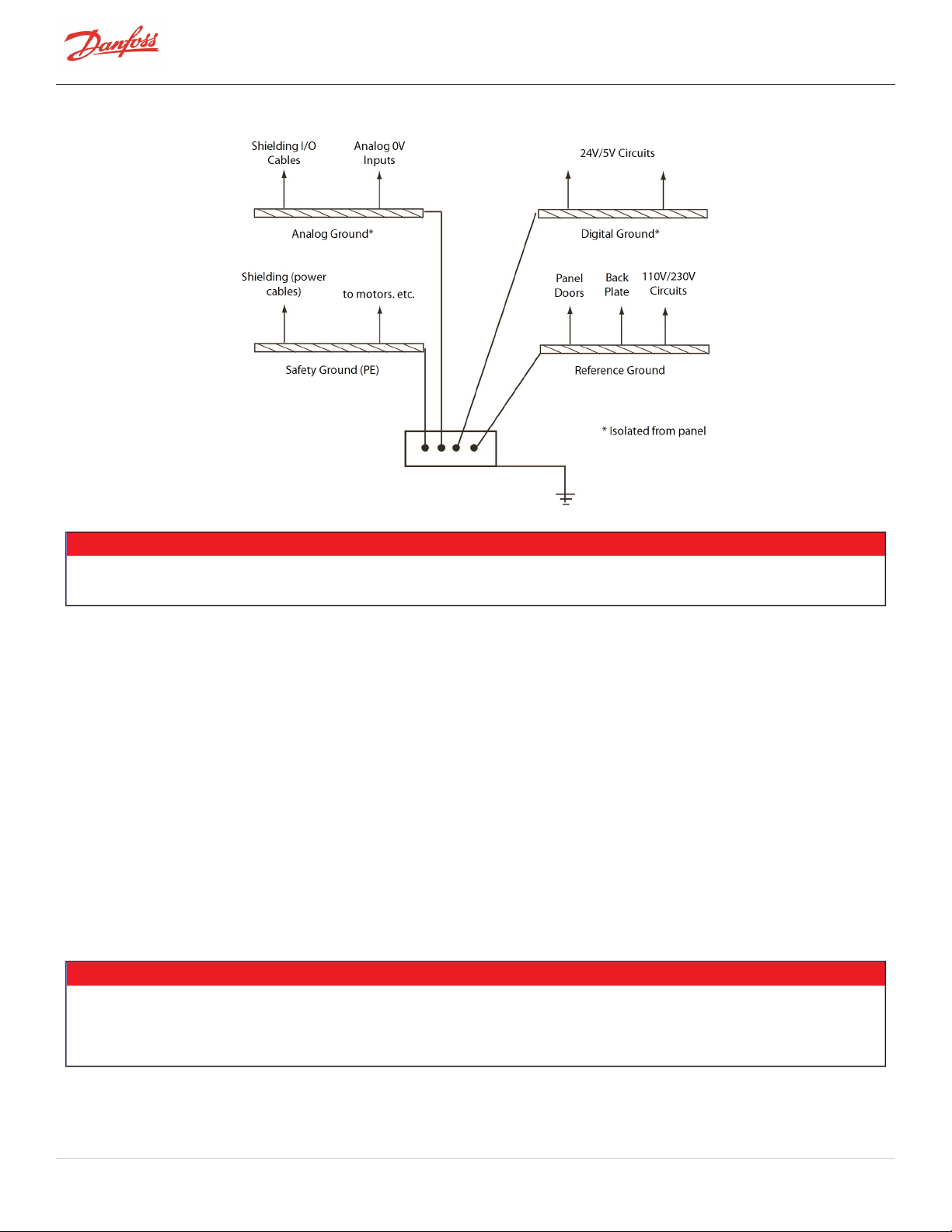
Figure 6-1 Typical Ground Connections
NOTE
Application of Turbocor compressors in any power system without a standard earth ground system should be reviewed and approved by
the Turbocor application organization.
6.13 Equipment Panel
Normally, the line reactor, EMI/EMC filter(s), and the harmonic filter will be installed in a panel. This could be the
same panel where the controls are located. When designing a panel, attention should be given to the following
recommendations:
l All metal parts should be properly connected to ensure an electrical connection. Connect panel doors
with braided cable.
l Keep power cables and interface cables separate. Use metal cable glands for shielded cables.
l The wire-loom going to the panel door should be shielded using a metal-braided hose that is
connected to ground at both ends.
l Electrical panel must have a dedicated ground conductor in accordance with relevant electrical safety
regulations.
l Verify that the panel ground conductor is sized in accordance with relevant electrical safety
regulations.
NOTE
l The installing electrical contractor is responsible for connecting the panel ground to the facility ground in accordance with
relevant electrical codes and standards, such as NEC Section 250 in the U.S. or its equivalent for other countries.
l Special filtering and measuring may be required in installations such as hospitals that are prone to being influenced by other
electronic equipment.
Page 50 of 136 - M-AP-001-EN Rev. S 9/8/2021
Page 51

6.14 Mains Input Cable Specification
The aim of electrical cables is to be a carrier (conductor) for electrical power. The influence of the power source on
the environment, or the influence of the environment on the power source, should be such that neither the proper
functioning of the compressor nor equipment in its environment is adversely affected. Therefore, Danfoss LLC
advises to use some type of shielded cable for the mains input.
When using shielded cable, select a cable with an effective shield. A cable with an aluminum foil will be far less
effective than a specially designed conductive braid. It is best to connect both ends of the cable shield to ground
since the shield is not part of the signal path. Alternatively, non-shielded conductors may be used if they are carried
inside of a code-approved electrical metallic conduit of the flexible or rigid types.
The mains input cable should be CSA, UL, or CE approved, three-wire with a common shield and single ground. The
cable must be rated for 90°C (194°F) minimum at the maximum applicable current. It is recommended that the cable
be double-jacketed, e.g., teck cable type. Refer to Table 6-4 Main Cable Connector Plate Hole Sizes for cable gland
specifications.
Table 6-4 Main Cable Connector Plate Hole Sizes
Model 380V 400V 460V 575V
TTS300/TGS230 2.5" 2.5" 2.5" 2.5"
TTS350/TGS310 2.5" 2.5" 3" N/A
TTS400/TGS390 2.5" 2.5" 3" 3"
TGS490 2.5" 2.5" 3" N/A
TTS700/TGS520 2.5" 2.5" 3" N/A
TTH375/TGH285 2.5" 2.5" 3" N/A
NOTE
The plate hole sizes shown in Table 6-4 Main Cable Connector Plate Hole Sizesare standard production sizes for standard compressors
released at the time of this publication. OEMs have the flexibility to change those sizes according to their needs. Please refer to the Spare
Parts Selection Guide for more information on available sizes or contact your Key Account Manager for possible changes. If OEMs are
ordering compressors using the New Type Code configuration the mains plate connector size can be selected at the time of order.
6.15 Idle Power Consumption
TTS/TGS/TTH/TGH series compressors have an idle power consumption of 45 W.
M-AP-001-EN Rev. S-9/8/2021 Page 51 of 136
Page 52

THISPAGEINTENTIONALLYLEFTBLANK
Page 52 of 136 - M-AP-001-EN Rev. S 9/8/2021
Page 53

Chapter 7.0 Compressor Performance
7.1 Performance Ratings
Compressor performance, including applicable capacity range, varies based on the operating conditions. The
capacity range, efficiency, and other operational information for each compressor can be determined only by using
the authorized software known as the Compressor Performance Rating (CPR) Engine or CPR Engine. This software
and a selection tool is available on our website.
7.2 Tolerance of Performance Ratings
The CPR rating conditions are based on flange-to-flange and do not take into effect any line pressure drops or
piping inconsistent with the guidance in the manual.
Compressors are guaranteed to meet the published performance ratings in the current CPR tool within the tolerance
band published in CPR. Higher accuracy is predicted in the speed only range and tolerance increases in the
mechanical unloading range (IGV < 110%). Higher tolerances are also published in the low lift and ultra-low lift
ranges. Refrigerant choice may also impact the rating tolerance.
M-AP-001-EN Rev. S-9/8/2021 Page 53 of 136
Page 54

THISPAGEINTENTIONALLYLEFTBLANK
Page 54 of 136 - M-AP-001-EN Rev. S 9/8/2021
Page 55

Chapter 8.0 Operating Envelopes
• • • CAUTION • • •
Rating Envelope Limits
The rating envelopes which follow are only a representative guide to the operating range of each compressor model. Be certain that
expected operation is verified by a rating using the most recent version of the CPR tool. If you have any questions about whether the
compressor you are rating is appropriate for the application conditions, please consult your local Danfoss LLC Application
Engineer for expert guidance.
Danfoss LLC has recently developed several variants of our compressors, each of which is designed to operate in a specific Saturated
Suction Temperature (SST) range. Danfoss LLC strongly urges selecting a compressor which covers the range of SST expected for the
application. Danfoss LLC will not accept responsibility for any rating discrepancies resulting from operation outside of the SST ranges in
these envelopes or those in the current CPR rating.
There are also possible cases where operation at SST condition limits above those specified and rated for a particular variant, but
operation may be limited by the maximum ambient temperature around the compressor, the saturated discharge temperature, and the
compressor power input. Before offering a compressor to the market above the SST limits of each variant, they must be validated by the
OEM through controlled testing at steady state conditions at the application conditions required for a minimum of 3.5 hours. This
validation test must be reviewed and approved by Danfoss LLC Applications to ensure the compressor is able to maintain stable
operation within the limits tested.
The BMCC does not prevent operation below the SST limit for some compressor variants. This flexibility is intended to permit operation
during transitional periods which may occur during a pull-down or batch loading process. Extended operation below the minimum SST
limits for a compressor variant may result in the rejection of a warranty claim if the root cause of the failure is determined to be related
to extended operation with SST below the variant limit.
M-AP-001-EN Rev. S-9/8/2021 Page 55 of 136
Page 56
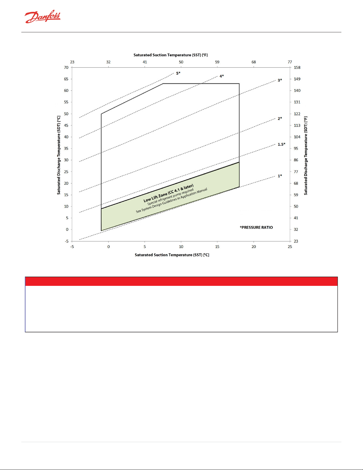
Figure 8-1 Operating Envelope
(1)
, Standard SST: TTS300 and TGS230
NOTE
The maximum Saturated Discharge Temperature (SDT) of the operating envelope represents the limit for compressors with maximum FLA
settings. The SDT for a compressor with a lower maximum current rating is lower than that shown and is related to the FLA rating of the
particular compressor.
The lower limit is related to minimum pressure ratios required to effect proper motor and power electronics cooling with standard
refrigerant circuit components.
(1)
The actual obtainable capacity will be dependent on specific operating characteristics of each compressor model.
Refer to the current authorized compressor selection/rating software for more exact values and conditions.
Page 56 of 136 - M-AP-001-EN Rev. S 9/8/2021
Page 57

Figure 8-2 Operating Envelope
(1)
, Medium Temperature: TTS300 and TGS230
NOTE
The maximum SDT of the operating envelope represents the limit for compressors with maximum FLA settings.
The SDT for a compressor with a lower maximum current rating is lower than that shown and is related to the FLA rating of the particular
compressor. The lower limit is related to minimum pressure ratios required to effect proper motor and power electronics cooling with
standard refrigerant circuit components.
(1)
The actual obtainable capacity will be dependent on specific operating characteristics of each compressor model.
Refer to the current authorized compressor selection/rating software for more exact values and conditions.
M-AP-001-EN Rev. S-9/8/2021 Page 57 of 136
Page 58

Figure 8-3 Operating Envelope
(1)
, Standard SST: TT350, TGS310, and TGS490
NOTE
The maximum SDT of the operating envelope represents the limit for compressors with maximum FLA settings.
The SDT for a compressor with a lower maximum current rating is lower than that shown and is related to the FLA rating of the particular
compressor. The lower limit is related to minimum pressure ratios required to effect proper motor and power electronics cooling with
standard refrigerant circuit components.
(1)
The actual obtainable capacity will be dependent on specific operating characteristics of each compressor model.
Refer to the current authorized compressor selection/rating software for more exact values and conditions.
Page 58 of 136 - M-AP-001-EN Rev. S 9/8/2021
Page 59

Figure 8-4 Operating Envelope
(1)
, High SST: TTS350, TGS310, and TGS490
NOTE
The maximum SDT of the operating envelope represents the limit for compressors with maximum FLA settings.
The SDT for a compressor with a lower maximum current rating is lower than that shown and is related to the FLA rating of the particular
compressor. The lower limit is related to minimum pressure ratios required to effect proper motor and power electronics cooling with
standard refrigerant circuit components.
(1)
The actual obtainable capacity will be dependent on specific operating characteristics of each compressor model.
Refer to the current authorized compressor selection/rating software for more exact values and conditions.
M-AP-001-EN Rev. S-9/8/2021 Page 59 of 136
Page 60

Figure 8-5 Operating Envelope
(1)
, Standard SST: TTS400 and TGS390
NOTE
The maximum SDT of the operating envelope represents the limit for compressors with maximum FLA settings.
The SDT for a compressor with a lower maximum current rating is lower than that shown and is related to the FLA rating of the particular
compressor. The lower limit is related to minimum pressure ratios required to effect proper motor and power electronics cooling with
standard refrigerant circuit components.
(1)
The actual obtainable capacity will be dependent on specific operating characteristics of each compressor model.
Refer to the current authorized compressor selection/rating software for more exact values and conditions.
Page 60 of 136 - M-AP-001-EN Rev. S 9/8/2021
Page 61

Figure 8-6 Operating Envelope
(1),
High SST: TTS400 and TGS390
NOTE
The maximum SDT of the operating envelope represents the limit for compressors with maximum FLA settings.
The SDT for a compressor with a lower maximum current rating is lower than that shown and is related to the FLA rating of the particular
compressor. The lower limit is related to minimum pressure ratios required to effect proper motor and power electronics cooling with
standard refrigerant circuit components.
(1)
The actual obtainable capacity will be dependent on specific operating characteristics of each compressor model.
Refer to the current authorized compressor selection/rating software for more exact values and conditions.
M-AP-001-EN Rev. S-9/8/2021 Page 61 of 136
Page 62

Figure 8-7 Operating Envelope
(1)
, Standard SST: TTS700 and TGS520
NOTE
The maximum SDT of the operating envelope represents the limit for compressors with maximum FLA settings.
The SDT for a compressor with a lower maximum current rating is lower than that shown and is related to the FLA rating of the particular
compressor. The lower limit is related to minimum pressure ratios required to effect proper motor and power electronics cooling with
standard refrigerant circuit components.
(1)
The actual obtainable capacity will be dependent on specific operating characteristics of each compressor model.
Refer to the current authorized compressor selection/rating software for more exact values and conditions.
Page 62 of 136 - M-AP-001-EN Rev. S 9/8/2021
Page 63

Figure 8-8 Operating Envelope
(1)
, High SST: TTS700, and TGS520
NOTE
The maximum SDT of the operating envelope represents the limit for compressors with maximum FLA settings.
The SDT for a compressor with a lower maximum current rating is lower than that shown and is related to the FLA rating of the particular
compressor. The lower limit is related to minimum pressure ratios required to effect proper motor and power electronics cooling with
standard refrigerant circuit components.
(1)
The actual obtainable capacity will be dependent on specific operating characteristics of each compressor model.
Refer to the current authorized compressor selection/rating software for more exact values and conditions.
M-AP-001-EN Rev. S-9/8/2021 Page 63 of 136
Page 64

Figure 8-9 Operating Envelope
(1),
Standard SST: TTH375/TGH285
NOTE
The maximum SDT of the operating envelope represents the limit for compressors with maximum FLA settings.
The SDT for a compressor with a lower maximum current rating is lower than that shown and is related to the FLA rating of the particular
compressor. The lower limit is related to minimum pressure ratios required to effect proper motor and power electronics cooling with
standard refrigerant circuit components.
(1)
The actual obtainable capacity will be dependent on specific operating characteristics of each compressor model.
Refer to the current authorized compressor selection/rating software for more exact values and conditions.
Page 64 of 136 - M-AP-001-EN Rev. S 9/8/2021
Page 65

Figure 8-10 Operating Envelope
(1),
Medium Temperature: TTH375/TGH285
NOTE
The maximum SDT of the operating envelope represents the limit for compressors with maximum FLA settings.
The SDT for a compressor with a lower maximum current rating is lower than that shown and is related to the FLA rating of the particular
compressor. The lower limit is related to minimum pressure ratios required to effect proper motor and power electronics cooling with
standard refrigerant circuit components.
(1)
The actual obtainable capacity will be dependent on specific operating characteristics of each compressor model.
Refer to the current authorized compressor selection/rating software for more exact values and conditions.
M-AP-001-EN Rev. S-9/8/2021 Page 65 of 136
Page 66

THISPAGEINTENTIONALLYLEFTBLANK
Page 66 of 136 - M-AP-001-EN Rev. S 9/8/2021
Page 67

Chapter 9.0 Minimum Unloading Capacity
Due to the nature of centrifugal compression, the minimum stable load is dependent on the pressure ratio imposed
on the compressor by the chiller system. All compressor performance, including unloading, should be determined
through use of the relevant compressor selection/rating programs.
M-AP-001-EN Rev. S-9/8/2021 Page 67 of 136
Page 68

THISPAGEINTENTIONALLYLEFTBLANK
Page 68 of 136 - M-AP-001-EN Rev. S 9/8/2021
Page 69

Chapter 10.0 Control Logic Guidelines for Multiple Compressors
Due to the nature of centrifugal compression, special control logic must be implemented for proper staging of
multiple Danfoss LLC compressors when installed on a common circuit. This section is intended only as a guide
without going into details. Control details are specific to each OEM’s individual control strategy. The Danfoss LLC
centrifugal compressors can be controlled by staging compressors and running the on line compressors in parallel.
Staging valve: The Staging valve is piped in upstream of the check valve to provide a low pressure bypass path and
is used to reduce the pressure ratio in the system to assist in startup and shutdown of a compressor. Staging valves
are mandatory for all Danfoss LLC compressors.
Load balancing valve (hot gas bypass): The Load Balance Valve (LBV) is piped downstream of the check valve and
is primarily used in low load conditions to keep the compressor operational instead of cycling off. It is possible to
use a staging valve as a LBV but sizing and control can be a little more challenging and for that reason they are both
frequently installed in many systems.
For additional details related to starting, stopping, staging, for all aspects of single and multiple compressor control,
please consult the OEM Programming Manual.
NOTE
The hot gas evacuated by the staging valve must be injected downstream of the main EXV in order to desuperheat the gas prior to
entering the suction of the compressor.
• • • CAUTION • • •
If the staging valve is used as a LBV, there are two major risks:
l Check valve chattering if the bypassed flow is too high, this chattering will lead to bearing faults due to vibrations (Please
contact Danfoss LLC for further information)
l High suction superheat which may lead to compressor fault
Staging valve sizing method: Using CPR, rate a compressor at the maximum pressure ratio for which the chiller is
designed to operate. Use the maximum Evaporator Mass Flow Rate to select an appropriately sized staging valve.
Load Balancing Valve Sizing: Using CPR, rate the compressor at the minimum load and conditions at which the
compressor is expected to operate. Use the Evaporator Mass Flow Rate to determine the required mass flow which
must be bypassed through the load balance valve to reach the desired minimum load.
NOTE
Danfoss LLC highly recommends the use of a solenoid valve as a staging valve as it is faster to provide pressure relief to the compressor in
case of emergency shutdown. We recommend to command the Solenoid valve with the "compressor status" contact on the I/O board.
Staging valve (solenoid type) can be selected from Danfoss portfolio e.g., EVR32 for TTS300 & TTS350 and EVR40 for TTS400 & TTS700
compressors. These valves should provide satisfactory starting and shutdown functionality, however Danfoss LLC Applications strongly
recommends testing with supervision of an Application Engineer to ensure proper operation during all start and stop conditions.
M-AP-001-EN Rev. S-9/8/2021 Page 69 of 136
Page 70

THISPAGEINTENTIONALLYLEFTBLANK
Page 70 of 136 - M-AP-001-EN Rev. S 9/8/2021
Page 71
Chapter 11.0 Product Certification
All TTS/TGS/TTH/TGH Series compressors are ETL listed and CE marked and have been tested in accordance with UL
60335-2-34:2017 Ed.6, CSA C22.2 No. 60335-2-34:2017 Ed.2 and EN 60335-2-34:2013.
M-AP-001-EN Rev. S-9/8/2021 Page 71 of 136
Page 72

THISPAGEINTENTIONALLYLEFTBLANK
Page 72 of 136 - M-AP-001-EN Rev. S 9/8/2021
Page 73

Chapter 12.0 Guide Specifications
This section contains written specifications for the TTS/TGS/TTH/TGH series compressors for use in system design
specifications.
12.1 General
Construction shall utilize a two-stage, variable-speed, centrifugal compressor design requiring no oil for lubrication.
Compressor shall be constructed with cast aluminum casing and high-strength thermoplastic electronics enclosures.
The two-stage centrifugal impellers shall consist of cast and machined aluminum. The motor rotor and impeller
assembly shall be the only major moving parts.
12.2 Refrigerant
TTS and TTH compressors are designed for use with R134a and R513A while TGS and TGH compressors are designed
for use only with R1234ze(E) and R515B.
12.3 Compressor Bearings
The compressor shall be provided with radial and axial magnetic bearings to levitate the shaft, thereby eliminating
metal-to-metal contact, and thus eliminating friction and the need for oil. The magnetic bearing system shall consist
of front, rear, and axial bearings. Both the front and the rear bearings are to levitate the shaft at X and Y directions,
and the axial at Z direction. Each bearing position shall be sensed by position sensors to provide real-time
repositioning of the rotor shaft, controlled by onboard digital electronics.
12.4 Capacity Control
The compressor shall have a VFD for linear capacity modulation, high part-load efficiency, and reduced in-rush
starting current. It shall include an Inverter that converts the DC voltage to an adjustable three-phase AC voltage.
Signals from the compressor controller shall determine the inverter output frequency, voltage and phase, thereby
regulating the motor speed. In case of power failure, the compressor shall be capable of allowing for a normal de-
levitation and shutdown.
Compressor speed shall be reduced as condensing temperature and/or heat load reduces, optimizing energy
performance through the entire range of capacity. Capacity modulates infinitely as motor speed is varied across the
range. IGVs shall be built-in to further trim the compressor capacity in conjunction with the variable-speed control
to optimize compressor performance at low loads. Refer to Danfoss LLC Selection Software for performance
calculations and limits.
12.5 Compressor Motor
The compressor shall be provided with a direct-drive, high-efficiency, permanent-magnet synchronous motor
powered by PWM voltage supply. The motor shall be compatible with high-speed variable-frequency operation that
affords high-speed efficiency, compactness and soft start capability. Motor cooling shall be by liquid refrigerant
injection.
12.6 Compressor Electronics
The compressor shall include a microprocessor controller capable of controlling magnetic bearings and speed
control. The controller shall be capable of providing monitoring, including commissioning assistance, energy
outputs, operation trends, and fault codes via a Modbus interface.
12.7 Ancillary Devices
A check valve shall be installed on the discharge port of all compressors to protect against backflow of refrigerant
during coast down. It is recommended that the valve be located after the properly designed discharge cone
adapter; preferably close to the condenser in the packaged system. The system must include an appropriately sized
5% impedance Line Reactor. One Line Reactor is required for each compressor and cannot be shared among
multiple compressors. Please refer to the Spare Parts Selection Guide.
M-AP-001-EN Rev. S-9/8/2021 Page 73 of 136
Page 74

THISPAGEINTENTIONALLYLEFTBLANK
Page 74 of 136 - M-AP-001-EN Rev. S 9/8/2021
Page 75

Chapter 13.0 System Design Guidelines
In addition to the instructions detailed in the technical documentation set, this section provides basic guidelines
and requirements for the design and manufacture of systems equipped with Danfoss Turbocor compressors.
NOTE
The compressor internal safety control settings are designed to provide protection for the compressor only. Designers MUST provide
SYSTEM protection within their control design. Danfoss LLC will not be responsible for system protection other than the compressor.
13.1 General Requirements
1. Check for compliance with all installation, operating, commissioning, and service steps, as outlined in
the documentation set. Check for the appropriate operating envelope and minimum unloading
capacity for the intended application.
2. System components such as evaporators, condensers, valves, etc., should be properly selected and
sized for appropriate performance and compatibility with applied refrigerant.
3. The system suction and discharge piping should be properly designed and selected for minimum
pressure drop. Since the Turbocor compressor operates without lubricating oil, conventional piping
considerations that ensure oil return, such as multiple risers and traps, are not required. In most cases,
larger diameter lines will result in better compressor performance and efficiency.
4. For improved efficiency and better control, particularly at low load/low compression ratios, EXVs are
strongly recommended. To take advantage of low pressure ratio operation to improve low load
performance and efficiency, EXV capacity should be selected accordingly. Thermal expansion valves
(TXVs) are not recommended due to the general inability of these devices to adequately cover the
operating spectrum of centrifugal compressors, particularly at low compression ratios.
5. Take all necessary precautions to prevent any possibility of liquid floodback to the compressor. This
means consideration during the ON and OFF cycles, particularly in multiple compressor installations.
This WILL include, but is not limited to, the inclusion of a liquid line solenoid valve and piping,
evaporator and condenser arranged in a manner that prevents free drainage of liquid to compressor.
6. The refrigeration piping system must be clean and free of all debris, in accordance with refrigerationindustry best practices, as particles can damage the compressor.
7. The system control should not be designed based on pump down cycle. The system cannot be pumped
down due to the surge characteristics of centrifugal compressors.
8. Refer to Table 13-1 Recommended Minimum Copper Tube Size for recommended minimum pipe sizes.
Table 13-1 Recommended Minimum Copper Tube Size
TTS300/TGS230 TTS350/TGS310 TTS400/TGS390 TGS490 TTS700/TGS520 TTH375/TGH285
Suction 4" 4" 5" 5" 5" 4"
Discharge 2 5/8" 3 1/8" 4" 4" 4" 3 1/8"
NOTE
If steel pipe is used, the pipe must be selected to give the equivalent inside diameter to copper pipe.
Properly tapered trumpets with smooth transitions must be used to connect the compressor flanges to the
pipework.
The discharge line exit transition should not be at an angle greater than eight 8° inclusive. The suction line length
should be straight for 1.5 times the pipe diameter before entry into the compressor.
M-AP-001-EN Rev. S-9/8/2021 Page 75 of 136
Page 76

Figure 13-1 Discharge Cone to Illustrate the Piping Requirements
13.2 Economizer Option
Turbocor compressors use two stage centrifugal compression with interstage port availability. This feature provides
advantages of capacity and efficiency improvement when an economizer is installed. The improvements in
efficiency and capacity are a result of further sub-cooling of the liquid refrigerant. Two types of economizer
arrangements can be used: sub-cooler or flash tank. Refer to Figure 14-3 Typical Refrigeration Piping Schematic with
Flash Tank Economizer and Figure 14-4 Typical Refrigeration Piping Schematic with Closed Type Economizer.
Refrigerant must enter the compressor through the economizer port in a “gas” state. Care must be taken to ensure
that no liquid enters the compressor.
To determine compressor capacity and efficiency, the economizer performance rating option is available in the
Selection Software on the TT/TG Software Section of the Danfoss LLC web page (www. turbocoroem.com). The
circuit must be properly designed to reflect the specified heat exchanger approach with minimized pressure drops
across the liquid side and expansion side. Piping design, including expansion device selection and pipe sizing,
should be in accordance with best practices.
• • • CAUTION • • •
To prevent bypass of gas through an idle compressor the economizer refrigerant circuit should include an automatically actuated valve
which closes upon compressor shutdown.
• • • CAUTION • • •
All TTH and TGH compressors must have an economizer which is active above 2.0 Pressure Ratio and to prevent reverse rotation, a
normally closed solenoid valve installed in the interstage vapor line which must close immediately upon compressor shut down.
13.3 Motor/Electronics Cooling Requirements
NOTE
l Sub-cooled liquid must be fed to the motor/electronics cooling port of the compressor
l It must be in a pure liquid state with a minimum of 6°F (3.5°C) sub cooled at the connection point to the motor/electronics
cooling port of the compressor
NOTE
Filter dryer, sight glass and service valve must be fitted in the motor-cooling liquid line.
Page 76 of 136 - M-AP-001-EN Rev. S 9/8/2021
Page 77

It is essential that compressor motor and power electronics cooling is available immediately at start up. The
compressor motor cooling liquid feed line must be configured and located so this occurs. Recommended minimum
pipe size is 1/2” for all models. A larger size may be necessary in some situations such as systems with low
subcooling on start or extended piping runs. A full-flow filter/drier must be installed and a liquid sight glass must be
installed adjacent to each compressor. In multiple compressor systems, a single filter/dryer may serve multiple
compressors but each compressor must have a dedicated sight glass.
13.4 Electrical Requirements
Power is permanently connected to the compressor connection terminals. A line reactor must be connected in series
with the compressor connection. The line reactor enclosure or box should be properly ventilated to avoid
overheating.
13.5 Application-Specific Requirements
13.5.1 Medium Evaporating Temperature Application (TGS230/TTS300/TGH285/TTH375)
NOTE
Medium Evaporating Temperature is defined as between 0 and -10°C (between 32 and 14°F) for TTS300/TGS230 and between 0 and -18°C
(between 32 and -0.4°F) for TTH375/TGH285.
Check the operating envelope for limits, required compressor version, and accessories.
For medium-temperature applications, an evaporating pressure regulator, Type KVP, is included with the
compressor and must be installed external to the compressor between the main suction line and the
motor/electronics cooling outlet port adjacent to the inter stage port. The valve has a Solder ODF connection with
7/8" diameter (Danfoss KVP 22), set at a corresponding pressure to 0.8°C (34°F) saturated temperature (depending
on the used refrigerant). Refer to C.1 Pressure Regulating Valve Installation InstructionsThe motor/electronics
cooling outlet port is fitted with a 5/8” flare adapter.
NOTE
Danfoss LLC highly recommends the insulation of the suction and inter-stage pipe as well as the bottom of the compressor for MT
applications to prevent ice buildups.
13.5.2 High Evaporating Temperature Application (TGS310/TTS350/TGS490/TGS390/TTS400/TGS520/TTS700)
NOTE
l High Evaporating Temperature is defined as between 12 and 30°C (53.6 and 86°F) and only applies to
TGS310/TTS350/TGS490/TGS390/TTS400/TGS520/TTH700 compressors.
l The standard Evaporating Temperature is defined as between -1 and 12°C (30.2 and 53.6°F) and applies to all compressors.
l It is not recommended to run a High Evaporating Temperature compressor in Standard Evaporating Temperature conditions
as it will eventually lead to a failure.
1. Check the operating envelope for limits and always validate the application with CPR engine in order
to make sure the compressor will work properly.
2. Make sure not to run a High Evaporating Temperature compressor in Standard Evaporating
Temperature conditions as it will eventually lead to failure.
M-AP-001-EN Rev. S-9/8/2021 Page 77 of 136
Page 78

13.5.3 Limited Capacity at Low Pressure Ratios
Figure 13-2 Centrifugal Performance Dynamics illustrates the capacity reduction imposed by compressor logic
when a compressor is operated at low lift conditions without a low lift pump and without the low lift function
activated. This capacity limitation is common during a warm building pull down cycle during low ambient
conditions but can also be encountered under other operating conditions with extended operation with low
pressure ratios. If more capacity is desired during operation during low lift conditions the condensing temperature
can be increased, or alternatively the low lift pump and low lift function can be activated if the refrigeration system
is so equipped with these features. Reference Figure 14-1 Typical Refrigeration Piping Schematic. and the
OEMProgramming Manual for more details on operation of the low lift function.)
13.5.4 Low Lift Application
The standard TTS/TGS control limits compressor speed and capacity above a 1.5 pressure ratio to ensure adequate
motor/inverter cooling. When enabled, the low lift option is meant to enable increased compressor speed and
capacity at pressure ratios below 1.5. To ensure adequate cooling for extended operation with pressure ratios below
1.5, the chiller system must provide the subcooled refrigerant flow specified in Table 13-2 Low Lift Pump Sizing. An
OEM-supplied liquid refrigerant pump will be required in most circumstances/designs. If an adequate supply of
subcooled liquid is not provided, the compressor will limit speed and capacity to maintain safe operating
temperatures. If safe temperatures cannot be maintained, the compressor will fault. Repeated operation without
adequate motor cooling could result in damage to the compressor and evidence of such operation could limit
warranty coverage.
Refer to Figure 14-1 Typical Refrigeration Piping Schematic for a possible pump design and Table 13-2 Low Lift
Pump Sizing. Though each OEM may choose to use more sophisticated logic, a simplified control logic would turn
the pump on at pressure ratios below 1.5 and off when the pressure ratio rises to 1.7. By default, the low lift option is
not enabled. More details on enabling the low lift option and the alarm and faults associated with it are included in
the OEM Programming Manual.
Table 13-2 Low Lift Pump Sizing
Model Cooling Mass Flow (kg/s) Head (kPa)
ALL 0.06 310
Page 78 of 136 - M-AP-001-EN Rev. S 9/8/2021
Page 79

Figure 13-2 Centrifugal Performance Dynamics
NOTE
Contact Danfoss LLC Applications for compressor selection and technical advice.
M-AP-001-EN Rev. S-9/8/2021 Page 79 of 136
Page 80

THISPAGEINTENTIONALLYLEFTBLANK
Page 80 of 136 - M-AP-001-EN Rev. S 9/8/2021
Page 81
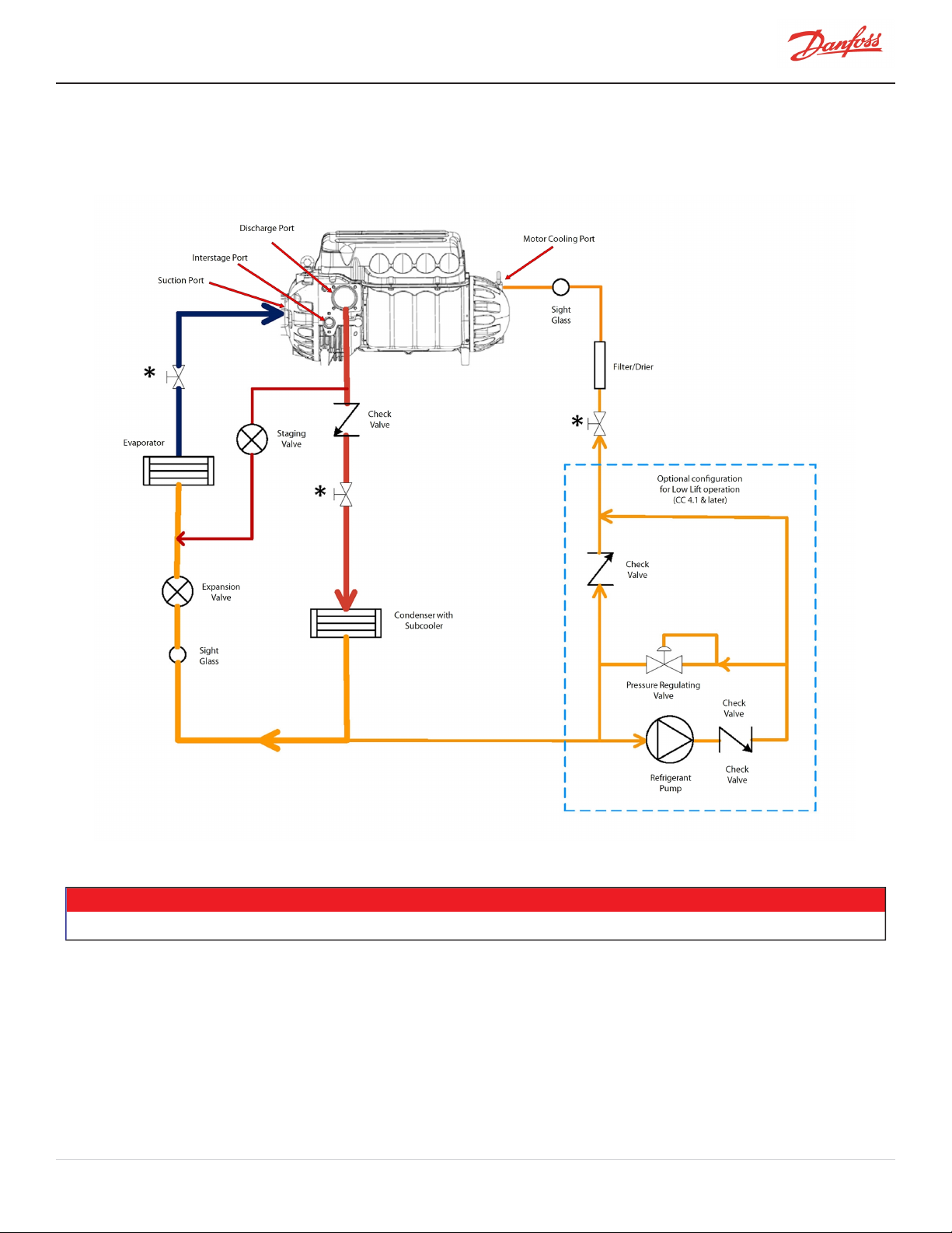
Chapter 14.0 Sample Refrigeration Circuits
Figure 14-1 Typical Refrigeration Piping Schematic
* Service valves are optional
NOTE
M-AP-001-EN Rev. S-9/8/2021 Page 81 of 136
Page 82

Figure 14-2 Typical Refrigeration Piping Schematic with Staging and Load Balancing Valve
* Service valves are optional
Page 82 of 136 - M-AP-001-EN Rev. S 9/8/2021
NOTE
Page 83
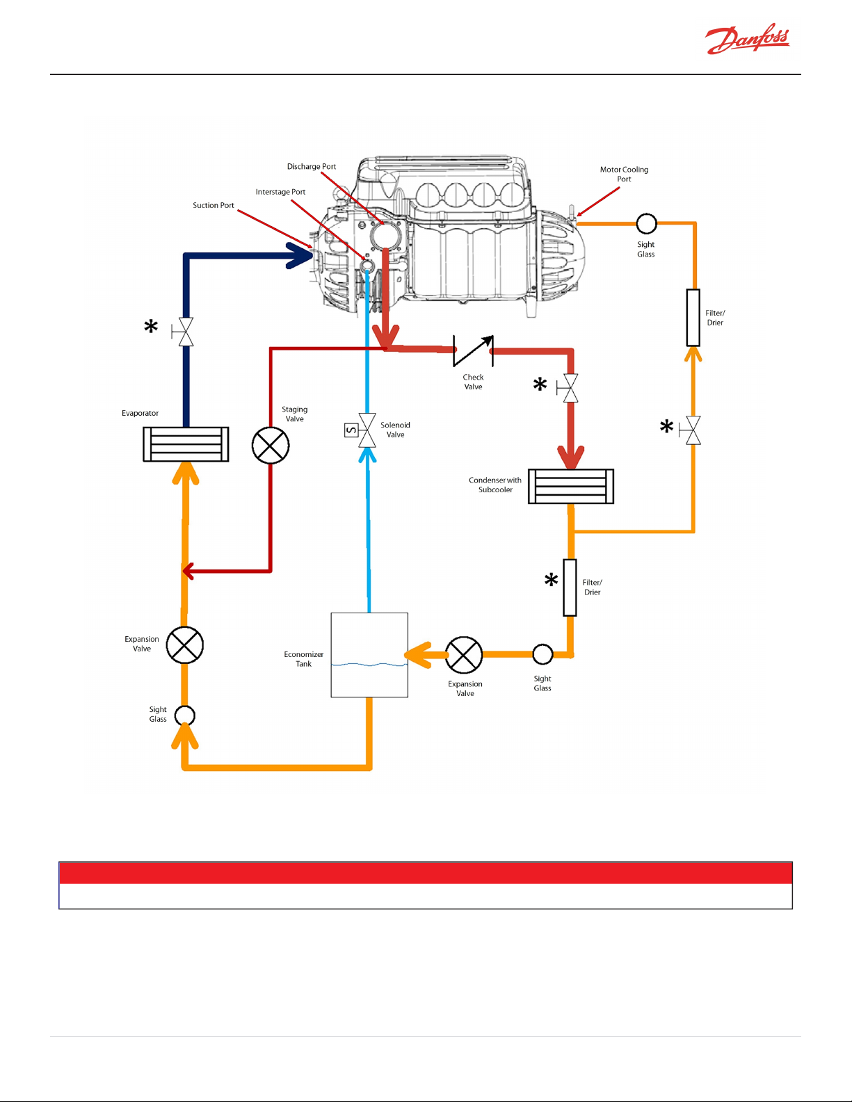
Figure 14-3 Typical Refrigeration Piping Schematic with Flash Tank Economizer
* Service valves are optional
NOTE
M-AP-001-EN Rev. S-9/8/2021 Page 83 of 136
Page 84
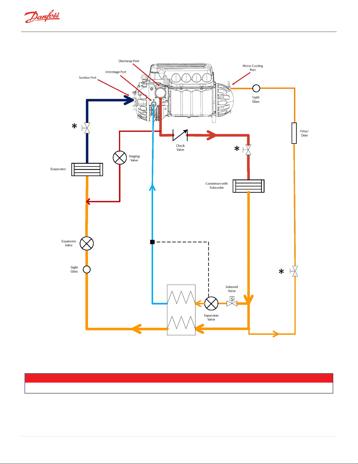
Figure 14-4 Typical Refrigeration Piping Schematic with Closed Type Economizer
* Service valves are optional
Page 84 of 136 - M-AP-001-EN Rev. S 9/8/2021
NOTE
Page 85
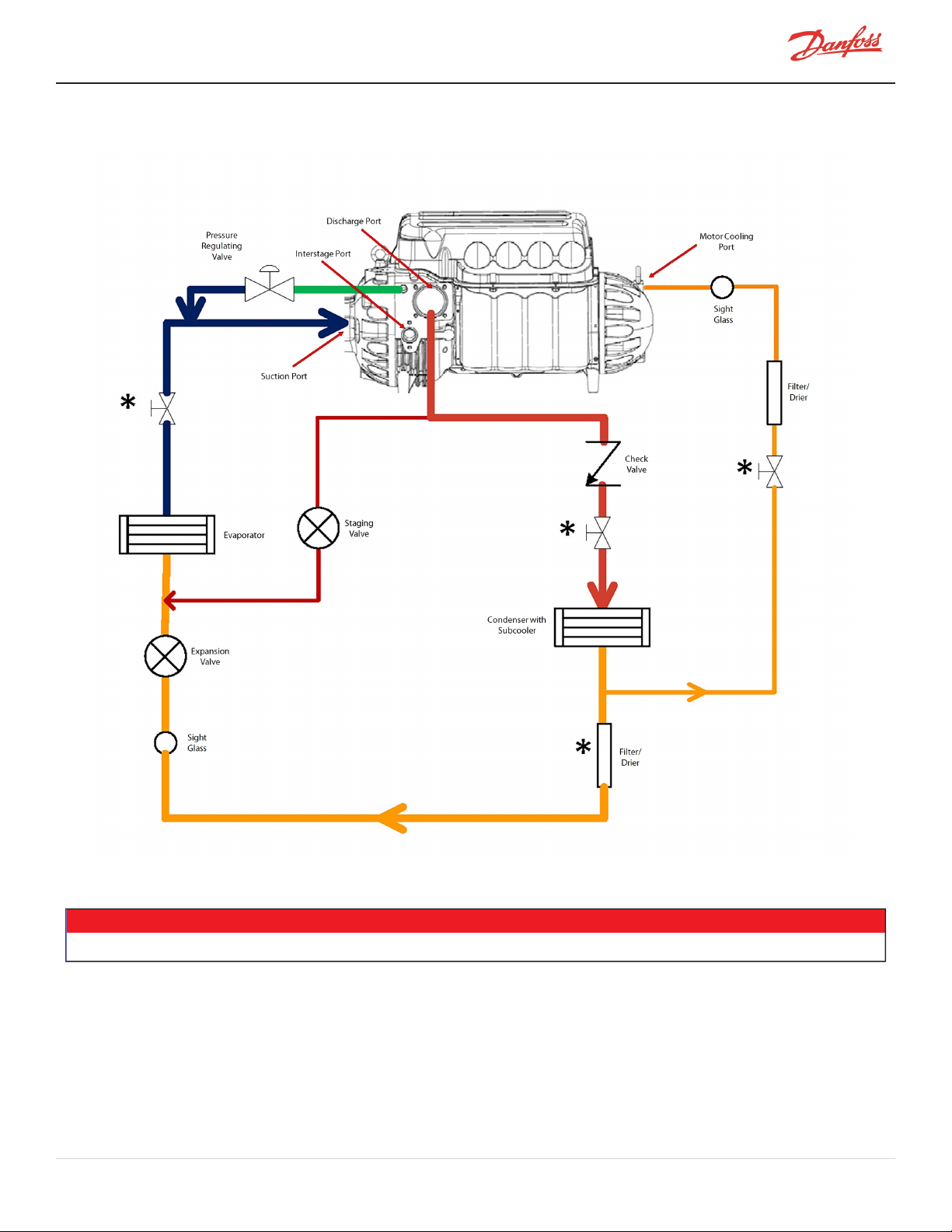
Figure 14-5 Typical Refrigeration Piping Schematic Using Motor-Cooling Pressure Regulating Valve (TTS300/TGS230 Medium
Temperature Compressors Only)
* Service valves are optional
NOTE
M-AP-001-EN Rev. S-9/8/2021 Page 85 of 136
Page 86
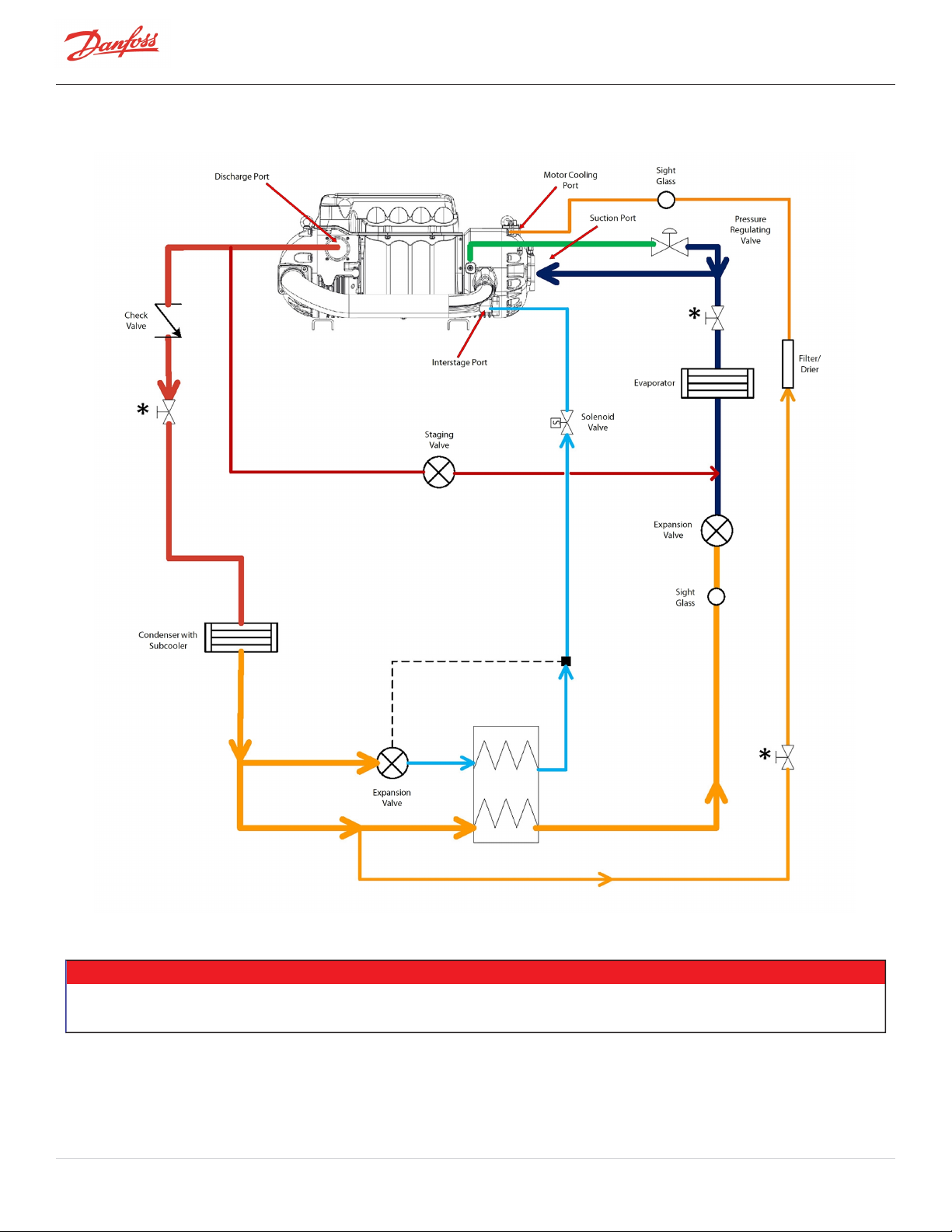
Figure 14-6 Typical Refrigeration Piping Schematic Using Motor-Cooling Pressure Regulating Valve (TTH/TGH Medium
Temperature Compressors Only)
l * Service valves are optional
l Closed type economizer shown; open type can also be used
Page 86 of 136 - M-AP-001-EN Rev. S 9/8/2021
NOTE
Page 87
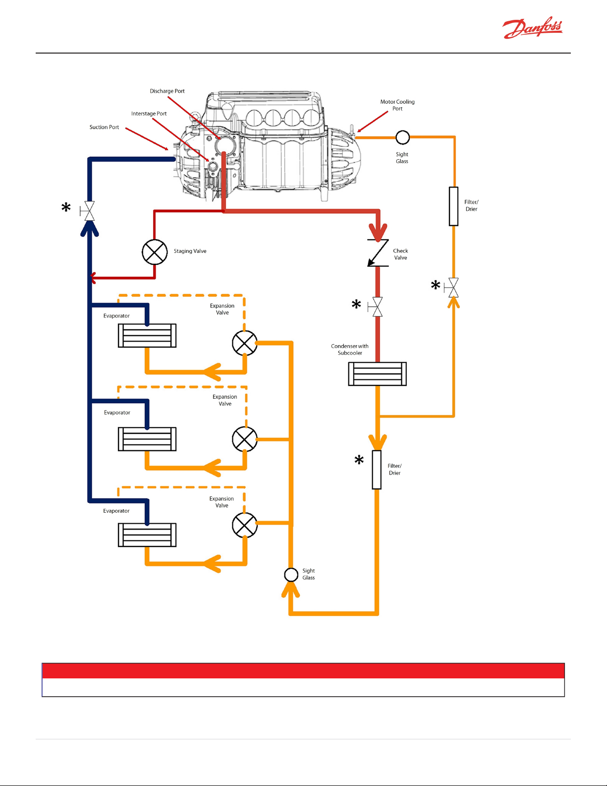
Figure 14-7 Typical Refrigeration Piping Schematic with Multiple DX Evaporators
* Service valves are optional
NOTE
M-AP-001-EN Rev. S-9/8/2021 Page 87 of 136
Page 88
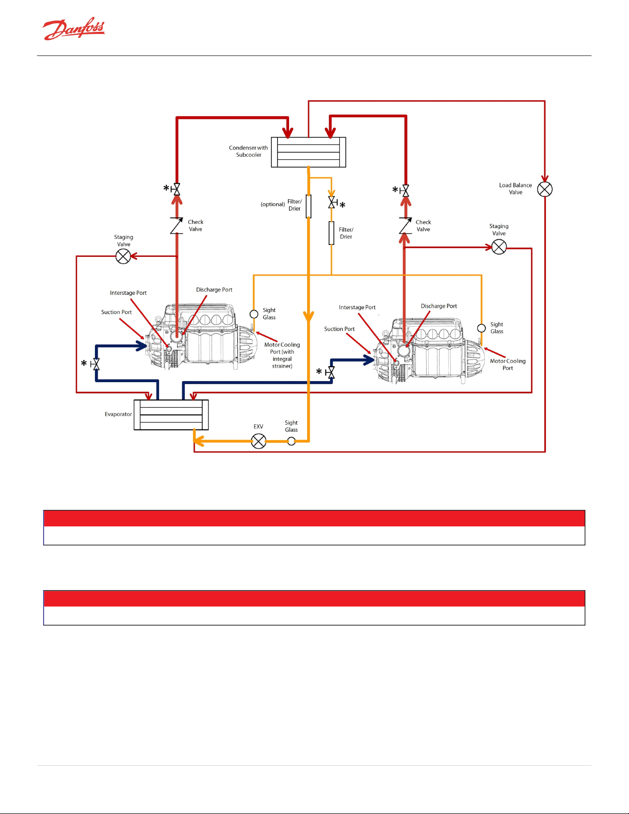
Figure 14-8 Multiple Compressors Single Circuit Piping Schematic
NOTE
Contact Danfoss LLC for compressor selection and further technical advice
NOTE
* Service valves are optional
Page 88 of 136 - M-AP-001-EN Rev. S 9/8/2021
Page 89
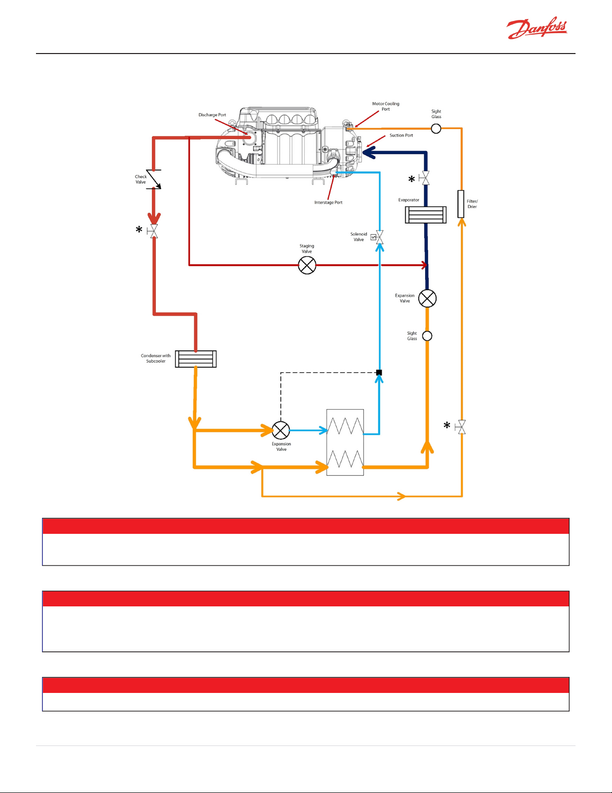
Figure 14-9 TTH/TGH Piping Schematic with Required Economizer (Closed Type) and Vapor Line Solenoid
NOTE
Failure to include a solenoid valve in the compressor VAPOR line, wired to close immediately when the compressor shuts down, could
result in serious damage to the compressor.
NOTE
All TGH/TTH compressors MUST include an active economizer (flash or plate style) when operated at pressure ratios above 2.0. If an
economizer is not active at pressure ratios above 2.0, significant instability should be expected and the operating range of the compressor
will not meet rated expectations. Economizer should be deactivated below PR 2.0
NOTE
* Service valves are optional
M-AP-001-EN Rev. S-9/8/2021 Page 89 of 136
Page 90

Figure 14-10 TTH/TGH Piping Schematic with Required Economizer (Flash Tank) and Vapor Line Solenoid
* Service valves are optional
Page 90 of 136 - M-AP-001-EN Rev. S 9/8/2021
NOTE
Page 91
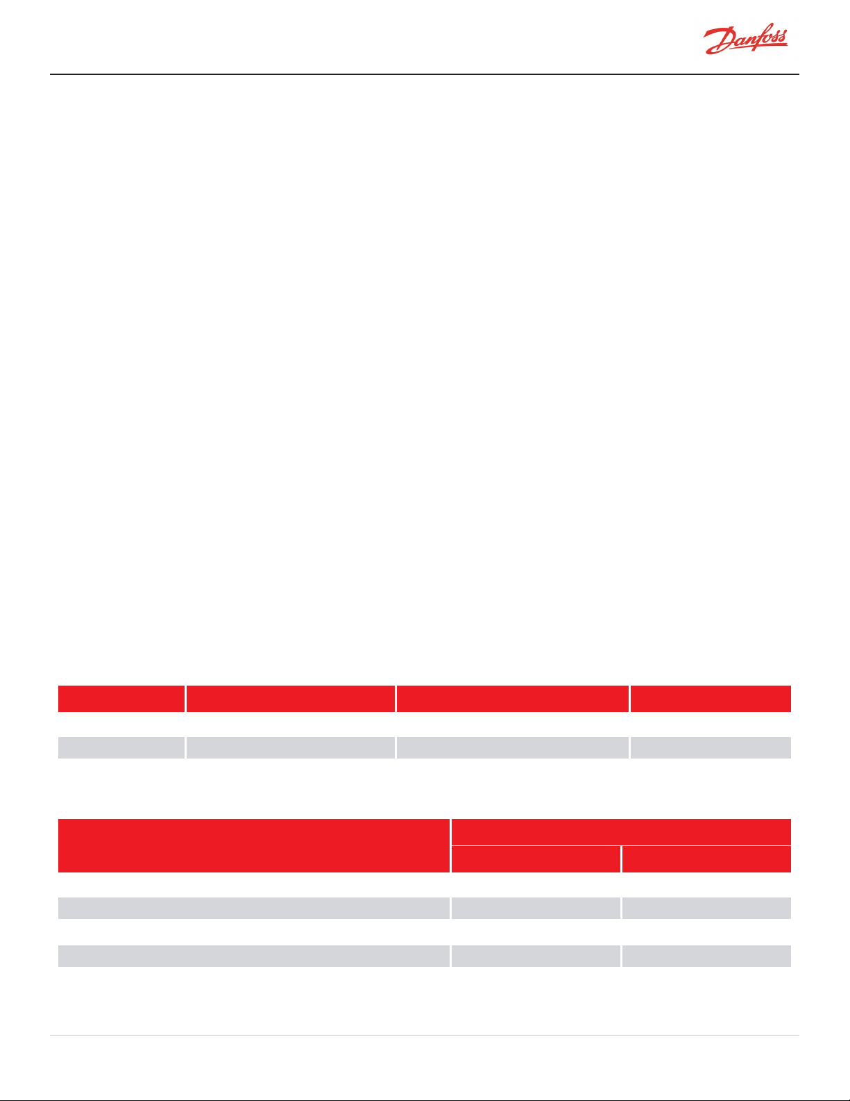
Chapter 15.0 Sound and Power Specifications
15.1 TTS300 and TTS400 Sound Power Measurements
The sound power levels on the TTS300 and TTS400 compressors are measured in compliance with ISO 9614-1 (1993)
and are given in decibels and in A-scale dB(A).
Three series of sound power measurements were performed on the unit while in two (2) different modes:
l For TTS300: 250kW (70 ton) refrigeration capacity
l 315kW (90 ton) refrigeration capacity
For TTS400:
l 420kW (120 ton) refrigeration capacity
l 525kW (150 ton) refrigeration capacity
15.1.1 Results
The sound power measured under each operational mode is presented in Table 15-1 Sound Power Measurements
for TTS300
l Table 15-1 Sound Power Measurements for TTS300
l Table 15-2 Sound Pressure Calculation for TTS300
l Table 15-4 Sound Power Measurements for TTS400
l Table 15-5 Sound Pressure Calculation for TTS400
These tables present the results of sound pressure calculations for various distances while the compressor is
installed on top of a building.
l The sound data below should be used as a guide only.
l The following sound measurements are based on a specific physical setup, such as suction/discharge
piping, evaporator and condensers, as well as specific pressure ratios. Any OEM system design would
not necessarily match these conditions.
l OEMs are responsible for their system sound level measurements and their published data.
Below are the results from “Sound Power Measurements"on a Turbocor TTS300 compressor.
Table 15-1 Sound Power Measurements for TTS300
Operation Mode Sound Power (A-Scale) dBA Sound Power (Linear Scale) dB Dominant Frequency
250 kW 81.5 81.5 1070 Hz
315 kW 86 85.5 1180 Hz
Table 15-2 Sound Pressure Calculation for TTS300
Operational Mode of Compressor (Capacity)
Distance in Relation to Compressor (Meters)
250 kW (70 Ton) dBA 315 kW (90 Ton) dBA
1 73.5 78.0
1.5 70.0 70.0
3 64 68.5
5 59.5 64.0
8 55.5 60.0
M-AP-001-EN Rev. S-9/8/2021 Page 91 of 136
Page 92

Table 15-3 Sound Power at Third Octave Band for TTS300
Sound Power, 250kW (70 Ton) Sound Power, 315kW (90 Ton)
Third octave band (Hz)
160 55.5 41.8 160 59.6 45.8
200 62.0 51.7 200 64.9 54.9
250 63.9 55.6 250 67.7 59.5
315 68.7 62.0 315 69.9 63.4
400 66.9 62.3 400 66.6 62.2
500 71.5 68.6 500 65.7 62.6
630 60.2 58.4 630 71.8 69.8
800 65.1 64.5 800 67.7 67.2
1000 76.5 76.7 1000 70.5 70.6
1250 66.2 66.9 1250 82.3 83.0
1600 69.9 71.0 1600 72.6 73.9
2000 69.6 70.9 2000 73.3 74.7
2500 68.6 69.9 2500 72.8 74.3
3150 72.3 73.6 3150 75.3 76.7
4000 71.3 72.3 4000 74.6 75.8
Linear scale
(dB)
A-weighted (dBA) Third octave band (Hz)
Linear scale
(dB)
A-weighted (dBA)
Table 15-4 Sound Power Measurements for TTS400
Operation Mode Sound Power (A-Scale) dBA Sound Power (Linear Scale)dB
420 kW (120 Ton) 88.4 89.1
525 kW (150 Ton) 88.1 89.2
Table 15-5 Sound Pressure Calculation for TTS400
Operational Mode of Compressor (Capacity)
Distance in Releation to Compressor (Meters)
420 kW (120 Ton) dBA 525 kW (150 Ton) dBA
1 80.5 80
1.5 77 76.5
3 71 70.5
5 66.5 66
8 62.3 62
Page 92 of 136 - M-AP-001-EN Rev. S 9/8/2021
Page 93

Table 15-6 Sound Power at Third Octave Band for TTS400
Sound Power, 420kW (120 Ton) Sound Power, 525kW (150 Ton)
Third octave band (Hz)
160 51 65 160 55 70
200 49 67 200 50 62
350 60 70 250 61 70
315 60 68 315 62 69
400 64 71 400 65 75
500 63 65 500 62 66
630 78 79 630 76 79
800 80 81 800 78 80
1000 83 82 1000 82 83
1250 82 81 1250 81 81
1600 77 76 1600 75 74
2000 77 76 2000 75 74
2500 75 74 2500 76 76
3150 75 75 3150 75 76
4000 72 71 400 73 73
Linear scale
(dB)
A-weighted (dBA) Third octave band (Hz)
Linear scale
(dB)
A-weighted (dBA)
M-AP-001-EN Rev. S-9/8/2021 Page 93 of 136
Page 94

THISPAGEINTENTIONALLYLEFTBLANK
Page 94 of 136 - M-AP-001-EN Rev. S 9/8/2021
Page 95

Chapter 16.0 Physical Data
This section contains data relative to compressor mounting, service clearance, and piping connections.
NOTE
The dimensions in the following figures show measurements in metric with imperial in parenthesis.
Table 16-1 Physical Dimensions
Model Length Width Height
TTS300/TGS230 788 mm
(31.02")
TTS350/TGS310/TGS490 788 mm
(31.02")
TTS400/TGS390 788 mm
(31.02")
TTS700/TGS520 788 mm
(31.02")
TTH375/TGH285 932 mm
(36.7")
518 mm
(20.4")
518 mm
(20.4")
518 mm
(20.4")
518 mm
(20.4")
590 mm
(23.2")
487 mm
(19.17)
487 mm
(19.17")
487 mm
(19.17")
487 mm
(19.17")
487 mm
(19.17")
16.1 Clearance
Adequate clearance around the compressor is essential to facilitate maintenance and service. Removal of the
compressor top and service-side covers requires a minimum clearance of 600 mm (24”) and 406 mm (16”),
respectively.
Shipping Weight
(Includes all shipping
material)
134 kg (296 lbs) 123.4 kg (272 lbs)
143 kg (315 lbs) 132 kg (291 lbs)
142 kg (312 lbs) 130.6 kg (288 lbs)
144 kg (318 lbs) 132 kg (294 lbs)
181 kg (400 lbs) 163.7 kg (361 lbs)
Compressor Total
Weight (Compressor
Only)
NOTE
If insulators are used at the four mounting base points, the overall height of the compressor will change. Be sure to measure accordingly
based on the insulator used.
M-AP-001-EN Rev. S-9/8/2021 Page 95 of 136
Page 96
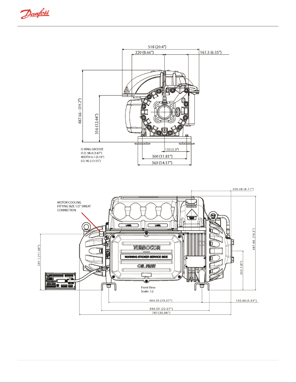
Figure 16-1 Suction View All Models (Excluding TTH/TGH Compressors)
Figure 16-2 Service Side View (Excluding TTH/TGH Compressors)
Page 96 of 136 - M-AP-001-EN Rev. S 9/8/2021
Page 97
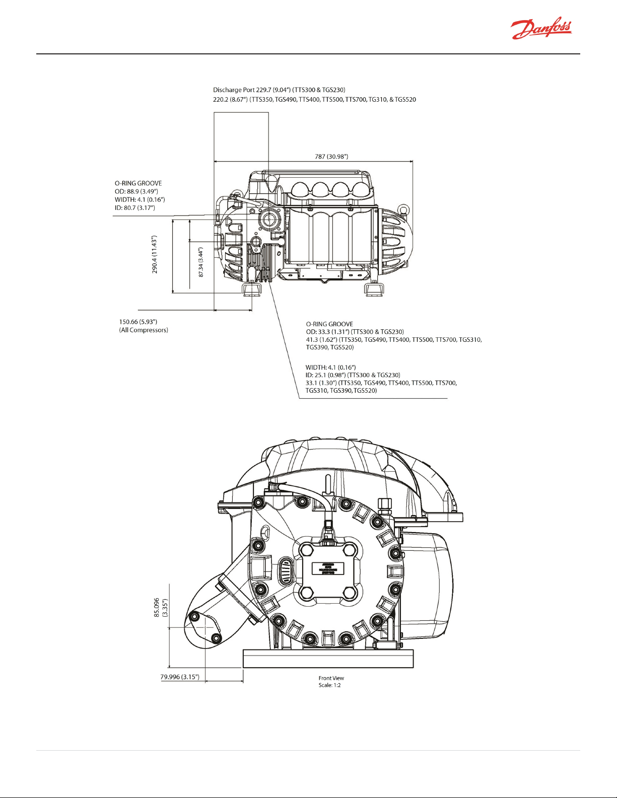
Figure 16-3 Discharge Side View (Excluding TTH/TGH Compressors)
Figure 16-4 TTH/TGH Suction Side View
M-AP-001-EN Rev. S-9/8/2021 Page 97 of 136
Page 98

Figure 16-5 TTH/TGH Service Side View
Figure 16-6 TTH/TGH Second Stage Housing View
Page 98 of 136 - M-AP-001-EN Rev. S 9/8/2021
Page 99

Figure 16-7 TTH/TGH Discharge Side View
Figure 16-8 Center of Gravity Capacitor Side View (Excluding TTH/TGH Compressors)
M-AP-001-EN Rev. S-9/8/2021 Page 99 of 136
Page 100
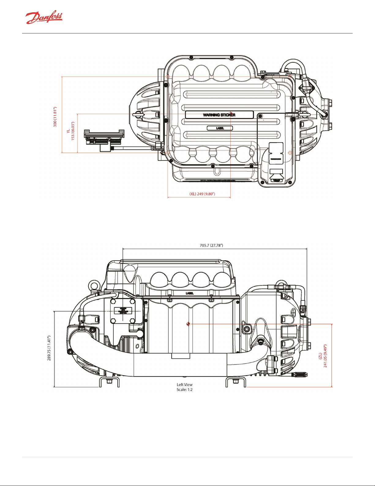
Figure 16-9 Center of Gravity Top View (Excluding TTH/TGH Compressors)
Figure 16-10 TTH/TGH Center of Gravity Capacitor Side View
Page 100 of 136 - M-AP-001-EN Rev. S 9/8/2021
 Loading...