

Page 1

Applications and Installation Manual - Revision N
®
Danfoss Turbocor® Twin-Turbine
Centrifugal Compressors
TT & TG Series Compressors
http://turbocor.danfoss.com
Page 2

THIS PAGE INTENTIONALLY LEFT BLANK
Page 2 of 108
M-AP-001-EN Rev. N
Page 3

Content
1 Introduction ........................................................................................................................................9
1.1 Scope ........................................................................................................................................................................................................9
1.2 Organization of this Manual ..............................................................................................................................................................9
1.3 Document Symbols ........................................................................................................................................................................... 10
1.4 Denitions ............................................................................................................................................................................................. 11
2 Overview of the TT/TG Compressor ................................................................................................15
2.1 TT/TG Compressor Nomenclature ................................................................................................................................................ 15
2.2 Refrigerant Type .................................................................................................................................................................................. 15
2.2.1 TG Series ..................................................................................................................................................................................... 15
2.3 Environment ........................................................................................................................................................................................ 16
2.4 Congurations of the TT/TG Compressor Models .................................................................................................................. 16
2.5 Compressor Module .......................................................................................................................................................................... 17
3 Functional Description ....................................................................................................................19
3.1 Main Fluid Path ...................................................................................................................................................................................19
3.2 Motor Cooling ..................................................................................................................................................................................... 20
3.3 Inlet Guide Vanes ............................................................................................................................................................................... 22
3.4 Compressor Control Overview ..................................................................................................................................................... 22
3.4.1 Motor Drive System ................................................................................................................................................................ 23
3.4.2 Soft-Start Board ....................................................................................................................................................................... 23
3.4.3 Bearing Motor Compressor Controller ............................................................................................................................ 23
3.4.4 Compressor Control ................................................................................................................................................................ 23
3.4.5 Capacity Control ....................................................................................................................................................................... 23
3.4.6 Expansion Valve Control ........................................................................................................................................................ 24
3.4.7 Motor/Bearing Control ........................................................................................................................................................... 24
3.4.8 Monitoring Functions ............................................................................................................................................................. 24
3.4.9 Abnormal Conditions ............................................................................................................................................................ 24
3.4.10 Bearing PWM Amplier ...................................................................................................................................................... 25
3.4.11 Serial Driver ............................................................................................................................................................................. 25
3.4.12 Backplane ................................................................................................................................................................................ 25
3.4.13 High-Voltage DC-DC Converter ....................................................................................................................................... 26
3.5 Magnetic Bearing System ............................................................................................................................................................... 26
3.5.1 Overview .................................................................................................................................................................................... 26
3.5.2 Bearing Control System ........................................................................................................................................................ 26
4 Control Interface Wiring ...................................................................................................................28
4.1 Control Wiring Connection Guidelines ...................................................................................................................................... 29
4.2 Interface Cable ................................................................................................................................................................................... 30
4.3 Compressor I/O Board Mounting Details .................................................................................................................................. 31
4.3.1 Compressor I/O Board - Mounting Instructions ........................................................................................................... 31
5 General Specications ......................................................................................................................33
5.1 Construction ........................................................................................................................................................................................ 33
5.2 Maximum Pressure ............................................................................................................................................................................ 33
5.3 Maximum Discharge Temperature ............................................................................................................................................... 34
5.4 Suction Pressure Limits ................................................................................................................................................................... 35
5.5 Codes and Standards Compliance .............................................................................................................................................. 35
6 Electrical Specications ...................................................................................................................37
6.1 Supply Voltage and Frequency..................................................................................................................................................... 37
6.2 Compressor Current Limit and Operating Range Settings.................................................................................................37
6.3 Disconnects ......................................................................................................................................................................................... 38
6.4 Motor Insulation Class ..................................................................................................................................................................... 39
6.5 AC Input Line/Power Electronic Component Protection .................................................................................................... 39
6.6 Power Line Contactor.......................................................................................................................................................................39
6.7 CE Compliance and EMI/EMC Filtering ...................................................................................................................................... 39
6.8 Surge Protection ................................................................................................................................................................................ 40
6.9 Harmonic Filtering (IEEE 519) ........................................................................................................................................................ 40
6.10 Grounding (Earth) Connection Guidelines ............................................................................................................................ 40
6.11 Equipment Panel ............................................................................................................................................................................. 41
6.12 Mains Input Cable Specication ................................................................................................................................................ 42
6.13 Idle Power Consumption .............................................................................................................................................................. 42
7 Compressor Performance ................................................................................................................43
7.1 Performance Ratings ......................................................................................................................................................................... 43
7.2 Tolerance of Performance Ratings ................................................................................................................................................ 43
M-AP-001-EN Rev. N
Page 3 of 108
Page 4

Content
8 Operating Envelopes ........................................................................................................................45
9 Minimum Unloading Capacity .........................................................................................................51
10 Control Logic Guidelines for Multiple Compressors ....................................................................53
11 Product Certication ......................................................................................................................55
12 Guide Specications .......................................................................................................................57
12.1 General................................................................................................................................................................................................ 57
12.2 Refrigerant ......................................................................................................................................................................................... 57
12.3 Compressor Bearings ..................................................................................................................................................................... 57
12.4 Capacity Control .............................................................................................................................................................................. 57
12.5 Compressor Motor .......................................................................................................................................................................... 57
12.6 Compressor Electronics ................................................................................................................................................................ 57
12.6.1 Ancillary Devices ................................................................................................................................................................... 57
13 System Design Guidelines .............................................................................................................59
13.1 General Requirements .................................................................................................................................................................. 59
13.2 Economizer Option ........................................................................................................................................................................ 60
13.3 Motor/Electronics Cooling Requirements ............................................................................................................................. 60
13.4 Electrical Requirements ................................................................................................................................................................ 61
13.5 Application-Specic Requirements .......................................................................................................................................... 61
13.5.1 Medium Evaporating Temperature Application (TT300) ....................................................................................... 61
13.5.2 Low Lift Application ............................................................................................................................................................. 61
13.5.3 Limited Capacity at Low pressure Ratios ..................................................................................................................... 62
14 Sample Refrigeration Circuits .......................................................................................................63
15 Sound and Power Specications ...................................................................................................71
15.1 TT300 and TT400 Sound Power Measurements ................................................................................................................... 71
15.1.1 Results ....................................................................................................................................................................................... 71
16 Physical Data ...................................................................................................................................75
16.1 Clearance ........................................................................................................................................................................................... 75
16.2 Center of Gravity ............................................................................................................................................................................. 77
16.3 Torque Specications..................................................................................................................................................................... 86
17 Piping Considerations ....................................................................................................................87
18 Environmental Considerations ......................................................................................................89
18.1 Humidity ............................................................................................................................................................................................ 89
18.2 Vibration ............................................................................................................................................................................................. 89
19 Shipping Considerations ...............................................................................................................91
19.1 Vibration ............................................................................................................................................................................................. 91
20 Installation ......................................................................................................................................93
20.1 Unpacking and Inspection .......................................................................................................................................................... 93
20.2 Rigging Requirements .................................................................................................................................................................. 93
20.3 Unit Placement ................................................................................................................................................................................ 93
20.4 Mounting Base ................................................................................................................................................................................. 94
20.5 Piping Connections ........................................................................................................................................................................ 95
20.6 Control Wiring ..................................................................................................................................................................................96
20.6.1 Control Wiring Connections ............................................................................................................................................. 96
20.6.2 Circuit Grounding ................................................................................................................................................................. 98
20.6.3 Voltage-Free Contacts ......................................................................................................................................................... 99
20.7 Power Wiring...................................................................................................................................................................................100
Appendix A: Power Line Accessories Installation .......................................................................... 103
A.1 Line Reactor Installation Instructions ....................................................................................................................................... 103
A.1.1 AC Line Cable Connection (From External Disconnect) ..........................................................................................103
A.1.2 AC Line Cable Connection (to Compressor Terminal) ..............................................................................................103
Appendix B: Power Line Accessories Installation .......................................................................... 105
B.1 EMI/EMC Filter Installation Instructions ...................................................................................................................................105
B.1.1 Line Side Connection ............................................................................................................................................................105
B.1.2 Load Side Connection ..........................................................................................................................................................105
B.1.3 Harmonic Filter........................................................................................................................................................................105
Page 4 of 108
M-AP-001-EN Rev. N
Page 5

List of Tables
Table 1-1 - Application Manual Applicability .....................................................................................................................................9
Table 1-2 - Denitions .............................................................................................................................................................................. 11
Table 2-1 - Refrigerant Used with Turbocor Compressors .......................................................................................................... 15
Table 3-1 - Backplane LEDs .................................................................................................................................................................... 25
Table 4-1 - Control Wiring Details ........................................................................................................................................................ 29
Table 5-1 - Discharge Pressure Alarm and Trip Settings ..............................................................................................................33
Table 5-2 - Discharge Temperature Trip Settings ........................................................................................................................... 34
Table 5-3 - Maximum Pressure Ratio Limits ..................................................................................................................................... 34
Table 5-4 - Maximum Allowable Pressure [PS] ................................................................................................................................ 34
Table 5-5 - Suction Pressure Alarm and Trip Settings ...................................................................................................................35
Table 6-1 - Acceptable AC Voltage Range .........................................................................................................................................37
Table 6-2 - Acceptable Frequency Range ......................................................................................................................................... 37
Table 6-3 - FLA and LRA Value Range ................................................................................................................................................. 38
Table 6-4 - Main Cable Connector Plate Hole Sizes ....................................................................................................................... 42
Table 13-1 - Recommended Minimum Copper Tube Size .......................................................................................................... 60
Table 13-2 - Low Lift Pump Sizing........................................................................................................................................................ 61
Table 15-1 - Sound Power Measurements for TT300 .................................................................................................................... 71
Table 15-2 - Sound Pressure Calculation for TT300 ....................................................................................................................... 71
Table 15-3 - Sound Power at Third Octave Band, TT300 Compressor ..................................................................................... 72
Table 15-4 - Sound Power Measurements ........................................................................................................................................ 72
Table 15-5 - Sound Pressure Calculation ........................................................................................................................................... 72
Table 15-6 - Sound Power at Third Octave Band of TT400 Compressor ................................................................................73
Table 16-1 - Physical Dimensions ......................................................................................................................................................... 75
Table 16-2 - Center of Gravity X-Y Coordinates ............................................................................................................................... 78
Table 16-3 - Screw Hole Specications ..............................................................................................................................................85
Table 16-4 - Torque Specications ....................................................................................................................................................... 86
M-AP-001-EN Rev. N
Page 5 of 108
Page 6

List of Figures
Figure 2-1 - Compressor Nomenclature ............................................................................................................................................15
Figure 2-2 - Major Components ........................................................................................................................................................... 16
Figure 3-1 - Compressor Fluid Path TG230 / TT300 ....................................................................................................................... 19
Figure 3-2 - Compressor Fluid Path ( TG310, TT350, TG390, TT400, TG520, and TT700) ................................................... 20
Figure 3-3 - Compressor Cooling Circuit (TG230 / TT300) .......................................................................................................... 21
Figure 3-4 - Compressor Cooling Circuit (TT300 Split-Cooling, TG310, TT350, TG390, TT400, and TG520) .............. 21
Figure 3-5 - Compressor Control System Functional Block Diagram ...................................................................................... 22
Figure 3-6 - Magnetic Bearing Conguration .................................................................................................................................. 26
Figure 3-7 - Magnetic Bearing Control System ...............................................................................................................................27
Figure 4-1 - Typical Control Wiring ...................................................................................................................................................... 28
Figure 4-2 - ModBus Grounding Diagram ........................................................................................................................................ 28
Figure 4-3 - I/O Wiring Specications ................................................................................................................................................. 30
Figure 4-4 - Compressor I/O Board ...................................................................................................................................................... 31
Figure 4-5 - Compressor I/O Board Installation .............................................................................................................................. 31
Figure 6-1 - Typical Ground Connections ......................................................................................................................................... 41
Figure 8-1 - Operating Envelope, TT300 and TG230 ..................................................................................................................... 45
Figure 8-2 - Operating Envelope, TT300 and TG230 (Medium Temperature Compressor) ............................................. 46
Figure 8-3 - Operating Envelope, TT350 and TG310 ..................................................................................................................... 47
Figure 8-4 - Operating Envelope, TT400 and TG390 .....................................................................................................................48
Figure 8-5 - Operating Envelope, TT700 and TG520 .....................................................................................................................49
Figure 13-1 - Centrifugal Performance Dynamics..........................................................................................................................62
Figure 14-1 - Typical Refrigeration Piping Schematic ................................................................................................................... 63
Figure 14-2 - Typical Refrigeration Piping Schematic With Staging and Load Balancing Valve .................................... 64
Figure 14-3 - Typical Refrigeration Piping Schematic With Flash Tank Economizer .......................................................... 65
Figure 14-4 - Typical Refrigeration Piping Schematic With Sub-Cooler Circuit Economizer .......................................... 66
Figure 14-5 - Typical Refrigeration Piping Schematic Using Motor-Cooling Pressure Regulating Valve
(Medium Temperature Compressors Only) ............................................................................................................ 67
Figure 14-6 - Typical Refrigeration Piping Schematic With Multiple DX Evaporators ....................................................... 68
Figure 14-7 - Typical Refrigeration Piping Schematic Using Multiple Compressors on a Common Circuit
With a Flooded Evaporator ........................................................................................................................................... 69
Figure 16-1 - Suction/Front View All Models ................................................................................................................................... 75
Figure 16-2 - Service Side View All Models ....................................................................................................................................... 76
Figure 16-3 - Discharge Side View ....................................................................................................................................................... 76
Figure 16-4a - Center of Gravity ........................................................................................................................................................... 77
Figure 16-4b - Center of Gravity ........................................................................................................................................................... 78
Figure 16-5 - Discharge Port Details (TT300 and TG230) ............................................................................................................ 79
Figure 16-6 - Discharge Port Details (TT350 and TG310) ............................................................................................................ 80
Figure 16-7 - Discharge Port Detail (TT400 and TG390) .............................................................................................................. 80
Figure 16-8 - Discharge Port Detail (TT700 and TG520) .............................................................................................................. 81
Figure 16-9 - Suction Port (All Models) .............................................................................................................................................. 82
Figure 16-10 - Suction Port Detail DD (All Models) ....................................................................................................................... 83
Figure 16-11 - Suction Port Detail DD (TT700 and TG520) ......................................................................................................... 83
Figure 16-12 - TT300 Flange Footprint Details ................................................................................................................................ 84
Figure 16-13 - TT350, TG310, TG390, and TT400 Flange Footprint Details ........................................................................... 84
Figure 16-14 - TT700 and TG520 Flange Footprint Details ......................................................................................................... 85
Figure 16-15 - Motor Cooling Fitting ..................................................................................................................................................86
Figure 19-1 - Anti-Vibration Bracket ................................................................................................................................................... 91
Figure 20-1 - Rigging Set-up .................................................................................................................................................................. 93
Figure 20-2 - Mounting Base (TT and TG series) ............................................................................................................................. 94
Figure 20-3 - Incorrect Compressor Mounting Pad Installation ............................................................................................... 94
Figure 20-4 - Correct Compressor Mounting Pad Installation ................................................................................................... 95
Figure 20-5 - Motor-Cooling Connection and Access Port ......................................................................................................... 96
Figure 20-6 - Compressor I/O Board Connections ......................................................................................................................... 97
Figure 20-7 - Interlock and Motor Speed Connections ................................................................................................................ 98
Figure 20-8 - Interlock Circuit Tests .....................................................................................................................................................99
Figure 20-9 - Typical Electrical Connections .................................................................................................................................. 100
Figure 20-10 - Ground Post Nuts ........................................................................................................................................................101
Figure 20-11 - Compressor AC Input Terminals ............................................................................................................................101
Figure A-1 - Line Reactor Connections ............................................................................................................................................104
Figure B-1 - Interconnection Layout .................................................................................................................................................106
Figure B-2 - Grounding Diagram ........................................................................................................................................................106
Page 6 of 108
M-AP-001-EN Rev. N
Page 7

Proprietary Notice
Copyright, Limitations of Liability and Revision Rights.
This publication contains proprietary information to Danfoss Turbocor Compressors (DTC).
By accepting and using this manual, the user agrees that the information contained herein
is utilized solely for operating DTC equipment or third party vendor equipment intended for
communication with DTC equipment over a serial communication link. This publication is
protected under the Copyright laws of the United States of America (USA) and most other
countries. The publication of this Guide is owned by DTC and is published as the most recent
revision as indicated on the Title page of this document. This document is for use by DTC
customers only; any use beyond the intended usage of this document is prohibited.
Tests have demonstrated that equipment will function as designed if the installation if
performed in accordance with the guidelines provided in this guide. However, DTC does not
guarantee the equipment performance will work in every physical, hardware or software
environment.
The guidelines provided in this manual are “AS-IS”, with no warranty of any kind, either
express or implied including; without limitation, any implied warranties of condition,
uninterrupted use, merchantability or tness for a particular purpose.
In no event shall DTC be liable for direct, indirect, special, incidental or consequential
damages arising out of the manufacture, use, or the inability to manufacture or use
information contained in this manual, even if advised of the possibility of such damages. In
particular, DTC is not responsible for any costs, including but not limited to those incurred as
a result of lost prots or revenue, loss of damage or equipment, loss of computer programs,
loss of data, the costs to substitute these, or any claims by third parties. In any event, DTC’s
total aggregate liability for all damages of any kind and type (regardless of whether based in
contract or tort) shall not exceed the purchase price of this product.
DTC reserves the right to revise this publication at any time and to make changes to its
contents without prior notice or any obligation to notify former or present users of such
revisions or changes.
Danfoss Turbocor Compressors Inc.
1769 East Paul Dirac Drive Tallahassee,
Florida 32310
USA
Phone 1-850-504-4800
Fax 1-850-575-2126
http://turbocor.danfoss.com
M-AP-001-EN Rev. N
Page 7 of 108
Page 8

THIS PAGE INTENTIONALLY LEFT BLANK
Page 8 of 108
M-AP-001-EN Rev. N
Page 9

Introduction
1 Introduction
1.1 Scope
Table 1-1 - Application
Manual Applicability
This Applications and Installation Manual is intended to be a guide for application data/
installation procedures specic to Danfoss Turbocor compressors. It is not intended to
inform on fundamental safety, refrigeration and electrical design skills. It is assumed and
presumed that persons using this manual are appropriately certied and have detailed
knowledge, experience and skills in respect to designing for and working with high pressure
refrigerants and medium voltage electrical components (to 1 KV high power AC & DC) as
well as complex control systems.
Some potential safety situations may not be foreseen or covered in this guide. Danfoss
Turbocor Compressors (DTC) assumes personnel using this manual and working on DTC
compressors are familiar with, and carry out all safe work practices necessary to ensure
safety for personnel and equipment.
This manual is designed for use with BMCC
software, Version 4.0.0 and later.
Manual Release Date BMCC Firmware Versions
M-AP-001-XX Rev E September 2013 CC 2.3.1213
M-AP-001-XX Rev L October 2016 CC 3.1.4
M-AP-001-XX Rev M November 2017 CC 4.0 and later
M-AP-001-XX Rev M.1 November 2017 CC 4.1 and later
M-AP-001-XX Rev N May 2018 CC 4.1 and later
1.2 Organization of
this Manual
This Applications and Installation Manual is divided into the following sections:
1. Overview of the TT/TG series compressors - provides an overview of the Twin-Turbo
and Total-Green (TT and TG) series compressors, including an introduction to the
compressor.
2. Compressor Module - provides details on the Compressor Module of the compressor,
including product capacity and application range, maximum pressure alarm and fault
limits.
3. System Design Guidelines - provides basic guidelines and requirements for the design
and manufacture of R134a, R513a, and R1234ze(E) systems equipped with DTC TT/TG
series compressors.
4. Installation Guidelines - describes application/installation procedures specic to
Danfoss Turbocor TT/TG compressors.
M-AP-001-EN Rev. N
Page 9 of 108
Page 10

Introduction
1.3 Document Symbols
The following symbols are used in this document.
NOTE: Indicates something to be noted by the reader.
NOTE
DANGER: Indicates an essential operating or maintenance procedure, practice, or
condition, which, if not strictly observed, could result in serious injury to or death of
personnel or long-term health hazards.
• • • DANGER • • •
WARNING: Indicates an essential operating or maintenance procedure, practice, or
condition which, if not strictly observed, could result in serious damage or destruction
of equipment.
• • • WARNING • • •
CAUTION: Indicates an essential operating or maintenance procedure, practice, or
condition which, if not strictly observed, could result in damage to equipment or potential
problems in the outcome of the procedure being performed.
• • • CAUTION • • •
Page 10 of 108
M-AP-001-EN Rev. N
Page 11

Introduction
1.4 Denitions
Table 1-2 - Denitions
Acronym / Term Denition
Alarms
AHRI Air-Conditioning, Heating, and Refrigeration Institute (www.ari.org; www.ahrinet.org)
ASHRAE
ASIC Application-Specic Integrated Circuit
ASTM American Society for Testing and Materials (www.astm.org)
Axial Bearing Bearing that controls the horizontal movement (Z axis) of the motor shaft
Backplane
Balance Piston
BMCC
Bus Bars Heavy-gauge metal conductors used to transfer large electrical currents
Capacitor A passive component that stores energy in the form of an electrostatic eld
Cavity Sensor
CE
Choke
Compression
Ratio
CSA Canadian Standards Association (www.csa.ca)
DC Bus
DC Capacitor
Assembly
DC-DC Converter
Dielectric
Diuser
Diode A two-terminal device between which current may ow in one direction only
Down-Trip Voltage
D-Sub
DTC Danfoss Turbocor compressors Inc.
EEPROM
EER Energy Eciency Ratio
Alarms indicate a condition at the limit of the normal operating envelope. compressor
alarms will still allow the compressor to run, but speed is reduced to bring the alarm
condition under the alarm limit.
American Society of Heating Refrigeration and Air-Conditioning Engineers (www.ashrae.
org)
A PCB for the purpose of power and control signal transmission. Many other components
connect to this board.
Component within the compressor that provides primary counter to impeller thrust.
Impeller thrust is trimmed by the axial bearing.
Bearing Motor compressor Controller. The BMCC is the central processor board of the
compressor. Based on its sensor inputs, it controls the bearing and motor system and
maintains compressor control within the operating limits.
NTC temperature sensor located behind the Backplane for the purpose of sensing motorcooling vapor temperature. Provides overheat protection to motor windings.
Conformance European. The CE marking (also known as CE mark) is a mandatory
conformity mark on many products placed on the single market in the European Economic
Area. The CE marking certies that a product has met EU health, safety, and environmental
requirements, which ensure consumer safety.
Denitive point on compressor map where mass ow rate is at maximum for compressor
speed and lift conditions.
The absolute discharge pressure divided by the absolute suction pressure
High DC voltage simultaneously connected to multiple compressor components via
metallic bus bars, including the capacitors
An assembly of four DC capacitors, four bleeder resistors, and positive and negative bus
bars
DC-DC converters supply and electrically isolate the high and low DC voltages that are
required by the control circuits. When the compressor is switched on, the High-Voltage
(HV) DC-DC Converter receives its 15VAC supply from the Soft-Start Board. Once the DC
bus voltage has risen to a pre-determined level, the HV DC-DC Converter’s onboard circuits
are powered by the DC bus (460-900VDC). The HV DC-DC Converter delivers +24VDC (with
respect to 0V) to the Backplane, and HV+ (+250VDC with respect to HV-) to the magnetic
Bearing Pulse Width Modulation (PWM) Amplier via the Backplane.
A dielectric is a nonconducting substance. Although “dielectric” and “insulator” are
generally considered synonymous, the term “dielectric” is more often used when
considering the eect of alternating electric elds on the substance while “insulator” is
more often used when the material is being used to withstand a high electric eld.
Part of a centrifugal compressor in the uid module that transforms the high-velocity, lowpressure gas exiting the impeller into higher-pressure, low-velocity gas discharged into the
condenser.
A voltage threshold where, if the incoming AC voltage drops below it, the SCRs will shut
down
A type of connector/plug (male and female) for control wiring. The RS-232 and large
connectors on either side of the I/O cable are both types of D-Sub connectors.
Electrically Erasable Programmable Read Only Memory. A small chip holds bits of data code
that can be rewritten and erased by an electrical charge, one byte at a time. EEPROM data
cannot be selectively rewritten; the entire chip must be erased and rewritten to update its
contents.
M-AP-001-EN Rev. N
Page 11 of 108
Page 12

Introduction
Acronym / Term Denition
EMC Electromagnetic Compatibility
EMF Electromotive Force
EMI Electromagnetic Interference
EMI Filter A circuit or device that provides electromagnetic noise suppression for an electronic device
EPC Extended Performance Compressor
ETL ETL Testing Laboratories, now a mark of Intertek Testing Services
EXV
Event Log
Faults (Critical)
Faults (Non-Critical)
Feedthrough
FIE Fully Integrated Electronics version of the compressor.
FLA Full Load Amps
Generator Mode
Genlanolin
Harmonics
HFC Hydrouorocarbon
HFC-134a A positive-pressure, chlorine-free refrigerant having zero ozone depletion potential.
Hermetic Motor A motor that is sealed within the refrigerant atmosphere inside the compressor.
ICD Integrated compressor Design
IEEE Institute of Electrical and Electronic Engineers (www.ieee.org)
IGBT Insulated Gate Bipolar Transistor. See Inverter.
IGV
Impeller
I/O Board
Inverter
IPLV Integrated Part Load Value
LBV
Electronic Expansion Valve. Pressure-independent refrigerant metering device driven by
electrical input
A record of events occurring during the compressor’s lifecycle, indicating when events and
faults occur and in what order. The event log is held in the BMCC.
Critical faults indicate an intolerable or unsafe condition that will result in equipment
failure if unchecked. They will cause the compressor controller to reduce speed and shut
down the system within 60 seconds. This type of fault requires a manual reset. Critical faults
include: Discharge Pressure Fault, 3-Phase Over-Current Fault, and Lock Out Fault. If any
of the following faults occur three times within a 30-minute period, they also will require
a manual reset: Inverter Temperature Fault, Cavity Temperature, SCR Temperature Fault,
Motor High Current Fault, and Motor back EMF is low.
Faults indicate an intolerable or unsafe condition that will result in equipment failure if
unchecked. They will cause the compressor controller to reduce speed and shut down the
system within 60 seconds. This type of fault has an automatic reset.
An insulated conductor connecting two circuits on opposite sides of a barrier such as a
compressor housing or PCB.
A function of the compressor where the stator becomes a generator, creating sucient
power to allow for the shaft to graduate slowly and drop onto the touchdown bearings
safely. This occurs when the inverter has insucient power to sustain safe and normal
operation and is typically due to a loss of power.
A type of grease. In certain climates where the dew point falls below the operating
temperature of some of the electronic components, it is necessary to apply Genlanolin to
certain parts of the compressor to prevent moisture accumulation.
Harmonics are multiples of the fundamental frequency distortions found in electrical
power, subjected to continuous disturbances.
Inlet Guide Vanes. The IGV assembly is a variable-angle guiding device that pre-rotates
refrigerant ow at the compressor intake and is also used for capacity control. The IGV
assembly consists of movable vanes and a motor. The vane angle, and hence, the degree of
pre-rotation to the refrigerant ow, is determined by the BMCC and controlled by the Serial
Driver. The IGV position can vary between approximately 0-percent and 110-percent open.
Rotating part of a centrifugal compressor that increases the pressure of refrigerant vapor
from the lower evaporator pressure to the higher condenser pressure.
Input/Output Board facilitating a connection between the compressor controller and/
or PC and the compressor. It allows the user to control the compressor and allows the
compressor to return status and sensor information to the user. Also known as the
Compressor Interface Module (CIM).
The Inverter converts the DC bus voltage into an adjustable frequency and adjustable
amplitude, three-phase simulated AC voltage.
Load Balance Valve. A modulating valve that can be installed to bypass discharge gas to the
inlet of the evaporator to provide gas ow at certain conditions such as startup, surge, and
further unloading of the compressor.
Page 12 of 108
M-AP-001-EN Rev. N
Page 13

Introduction
Acronym / Term Denition
LED Light-Emitting Diode
Levitation
Line Reactor
LLSV Liquid Line Solenoid Valve
LR Line Reactor
LRA Locked Rotor Amps
Mid Bus
Modbus
Monitor Program
MOP Maximum Operating Pressure
Motor Back EMF
NEC National Electric Code (www.necplus.org)
Nm Newton meter. A unit of torque. 1 Nm = 0.738 pound-force foot (lbf/f).
NTC
OEM Original Equipment Manufacturer
Open Impeller A compressor impeller with exposed vanes similar to a boat propeller or turbocharger.
PCB Printed Circuit Board
Permanent Magnet
Motor
PLC Programmable Logic Controller
Pressure Ratio See “Compression Ratio”
Proximity Sensor
PWM Pulse Width Modulation
Radial Bearing Bearings that control the position of the shaft on the X and Y axis.
Rectier A rectier is an electrical device that converts AC current to pulsating DC current.
Resistor
RMA Return Material Authorization
SCR
Serial Driver
SDT Saturated Discharge Temperature
SEER Seasonal Energy Eciency Ratio
The elevation or suspension of the compressor shaft by the magnetic eld created by the
magnetic bearings.
A transformer-like device designed to introduce a specic amount of inductive reactance
into a circuit. When this occurs, it limits the change in current in the line, which in turn
lters the waveform and attenuates electrical noise and harmonics associated with an
inverter/drive output.
A connection between the capacitors allowing them to be connected in series and in
parallel simultaneously. Two capacitors in a series make up the DC- and two in a series
make up the DC+, and those two sets of two are connected in parallel.
A serial communications protocol published by Modicon in 1979 for use with its
programmable logic controllers (PLCs). It has become a de facto standard communications
protocol in industry, and is now the most commonly available means of connecting
industrial electronic devices. Modbus allows for communication between many devices
connected to the same network, for example a system that measures temperature and
humidity and communicates the results to a computer.
A software program provided by DTC that can be downloaded to a PC or laptop computer
to monitor, regulate, control or verify the operation of a compressor.
Back electromotive force is a voltage that occurs in electric motors where there is relative
motion between the armature of the motor and the external magnetic eld and is also
a parameter used to evaluate the strength of the permanent magnets of the shaft. One
practical application is to use this phenomenon to indirectly measure motor speed as well
as estimate position.
Negative Temperature Coecient. Refers to thermistor characteristic. Decrease in
temperature results in a rise in resistance (ohms).
A motor that has permanent magnetism as opposed to electromagnetism
Sensors that are able to detect the presence of nearby objects without any physical
contact. A proximity sensor often emits an electromagnetic or electrostatic eld, or a beam
of electromagnetic radiation (infrared, for instance), and looks for changes in the eld or
return signal.
A resistor is an electrical component that limits or regulates the ow of electrical current in
an electronic circuit.
Silicon-Controlled Rectier. The SCR is a four-layer, solid-state device that controls current
and converts AC to DC.
A PCB plug-in responsible for the operation of the IGV stepper motor and optional
expansion valves. It contains four relays for the solenoid valves, compressor status and
compressor run status respectively.
M-AP-001-EN Rev. N
Page 13 of 108
Page 14

Introduction
Acronym / Term Denition
Shaft Orbit The path travelled by the compressor shaft relative to the bearing magnetic centers
Shrouded Impeller An impeller with boxed in, or “shrouded,” impeller blades, as opposed to an open impeller.
SIE Semi-Integrated Electronics version of the compressor.
Single-Stage
Centrifugal
compressor
Snubbers
Soft-Start Board /
SoftStarter
SST Saturated Suction Temperature
Surge
Thrust Bearing
Ton The basic unit for measuring the rate of heat transfer (12,000 BTU/H; 3.516 kw/H)
Touchdown
Bearings
TT Twin Turbine
Two-Stage
Centrifugal
compressor
TXV
UL Underwriters Laboratories (www.ul.com)
Up-Trip Voltage When the DC- bus reaches the up-trip voltage, the SCRs will be gated open continuously
VAC Volts Alternating Current
Vaned Diuser
Vaneless Diuser Similar to a Vaned Diuser, except that it does not possess any de-swirl vanes
VDC Volts Direct Current
VFD Variable Frequency Drive
Type of centrifugal compressor having one impeller.
Capacitors responsible for eliminating electrical noise/harmonics from the DC Bus before it
reaches the IGBT
The Soft-Start Board limits in-rush current by progressively increasing the conduction
angle of the SCRs. This technique is used at compressor startup while the DC capacitors are
charging up. The Soft-Start Board takes as input a 3-phase voltage source at 50/60Hz from
the input terminal and a DC voltage signal from the SCR output. In turn, it outputs pulses
to the SCR and provides power to the High-Voltage (HV) DC-DC Converter. All voltages
from the Soft-Start Board are with respect to the positive DC bus and not the compressor
ground.
The condition at which the compressor cannot sustain the discharge pressure, allowing
refrigerant to temporarily and rapidly re-enter the compressor uid path, creating a
cavitating eect. This is an undesirable situation that should be avoided.
A bearing that absorbs the axial forces produced in a centrifugal compressor by the
refrigerant pressure dierential across the impeller.
Carbon races or ball bearing for the purpose of preventing mechanical interference
between the shaft and the magnetic bearings should they lose power or fail.
Type of centrifugal compressor having two impellers. The rst-stage impeller raises the
pressure of the refrigerant vapor approximately halfway from the cooler pressure to the
condenser pressure, and the second-stage impeller raises the pressure the rest of the
way. With a two-stage compressor, an interstage economizer may be used to improve the
refrigeration cycle eciency
Thermal Expansion Valve. A pressure-dependent refrigerant metering device that operates
independently and is controlled by temperature.
An assembly of plates with curved vanes that serve to slow, compress, and reduce
refrigerant rotation as it enters the second-stage impeller
* Danfoss Turbocor’s commitment to excellence ensures continuous product improvements.
* Subject to change without notice.
Page 14 of 108
M-AP-001-EN Rev. N
Page 15

Overview of the TT/TG Compressor
2 Overview of the
TT/TG Compressor
2.1 TT/TG Compressor
Nomenclature
Figure 2-1 - Compressor
Nomenclature
The TT/TG Centrifugal series of compressors is a group of compressors that covers the
nominal capacity range from 90 to 200 Tons (TT) and 70 to 150 Tons (TG) tons.
The TT/TG series of compressors are an oil free centrifugal design based on magnetic
bearing technology.
TT300 - G - 1 - ST - E - CE
Series
TT300
TT350
TT400
TT700
TG230
TG310
TG390
TG520
Voltage**
D: 380V / 3Ph / 60Hz
E: 380V / 3Ph / 50Hz
F: 575V / 3Ph / 60Hz
G: 460V / 3Ph / 60Hz
H: 400V / 3Ph / 50Hz
J: 400V / 3Ph / 60Hz
Options
ST: Standard
MT: Medium Temp
HL: High Lift
Refrigerant
1: R-134a
2: R-22
3: R-1234ze (E)
4: R513A
Unit Classication
CE: With CE Mark
NC: Non-conductive Coating
CH: China
Major Revision
N, P, C, A, D, E, F, G...etc.
2.2 Refrigerant Type
2.2.1 TG Series
Table 2-1 - Refrigerant Used
with Turbocor Compressors
The TT series compressors are totally oil-free and optimized for use with refrigerant R134a.
The TG series compressor is for use with R1234ze(E) refrigerant only.
ASHRAE standard 34 has classied this refrigerant as “R1234ze(E) with safety classication of
A2L”. ASHRAE Standard 34, 2010 Addendum 1 contains the change to the standard.
ASHRAE Standard 15 (Safety Standard) has sent out an initial public review document
outlining proposed changes to this standard to address 2L refrigerants.
Compressor Refrigerant
TT series R134a/R513A
TG series R1234ze(E)
NOTE
Do not use recycled refrigerant as it may contain oil, which can aect system reliability. The refrigerant should be pure
and stored in virgin containers.
NOTE
To ensure a reliable chiller system, all system components, most notably expansion valves, solenoid valves, and sensors, be
appropriate for application in oil free systems as determined by the component manufacturer. In addition, all chiller system
components exposed to refrigerant should be approved by their manufacturer for use with that refrigerant.
M-AP-001-EN Rev. N
Page 15 of 108
Page 16

Overview of the TT/TG Compressor
2.3 Environment
TT/TG Compressor Models
Figure 2-2 - Major
Components
The compressor should not be operated at an altitude higher than 3000m.
The compressor should be stored and operated within the following ambient temperature
ranges:
• Storage: -30°C to 70°C (-22°F to 158°F)
• Operation: -1°C to 52°C (30°F to 125°F).
• Mains Power Applied Non Operating Limit: -25°C (-13°F)
• Humidity: 0-95% Non Condensing
NOTE
• Contact Danfoss Turbocor for lower ambient temperature operations. Refer to “Operating Envelopes,” for details of the
operating conditions. These conditions are in line with the AHRI 540 Standard.
• All compressors/components should be protected from environments that could cause corrosion to exposed metals. For
outdoor installations, a weather-proof enclosure with vents is recommended to house the compressor.
• TT/TG compressors can operate below -1°C ambient if refrigerant circuit is maintained at a minimum of -1°C Saturated
temperature.
The TT/TG compressor, motor and power assemblies are packaged in design. 2.4 Configurations of the
Soft Start Board
SCRs
Inverter
DC-DC
Converter
Backplane
Serial Driver
Bearing Motor Compressor
Controller (BMCC)
PWM Amplifier
Page 16 of 108
M-AP-001-EN Rev. N
Page 17

Overview of the TT/TG Compressor
2.5 Compressor Module
This section provides a brief overview of the Compressor Module.
The Compressor Module is comprised of three (3) portions:
• Aerodynamics - The aerodynamics portion manages the compression of refrigerant
through the compressor from suction to discharge comprising centrifugal and IGV
technologies.
• Motor - The motor portion contains a direct-drive, high-efficiency, permanent-magnet
synchronous motor powered by pulse-width-modulating (PWM) voltage supply.
The high-speed variable-frequency operation that affords high-speed efficiency,
compactness and soft start capability. Motor cooling is by liquid refrigerant
injection.
• Electronics - The electronics is divided into two (2) sections: Power electronics
located on the top of the compressor including soft-start, DC-DC, SCR, capacitors
and inverter. Control electronics located on the side of the compressor including:
backplane, BMCC, serial driver and PWM.
M-AP-001-EN Rev. N
Page 17 of 108
Page 18

THIS PAGE INTENTIONALLY LEFT BLANK
Page 18 of 108
M-AP-001-EN Rev. N
Page 19

Functional Description
3 Functional Description
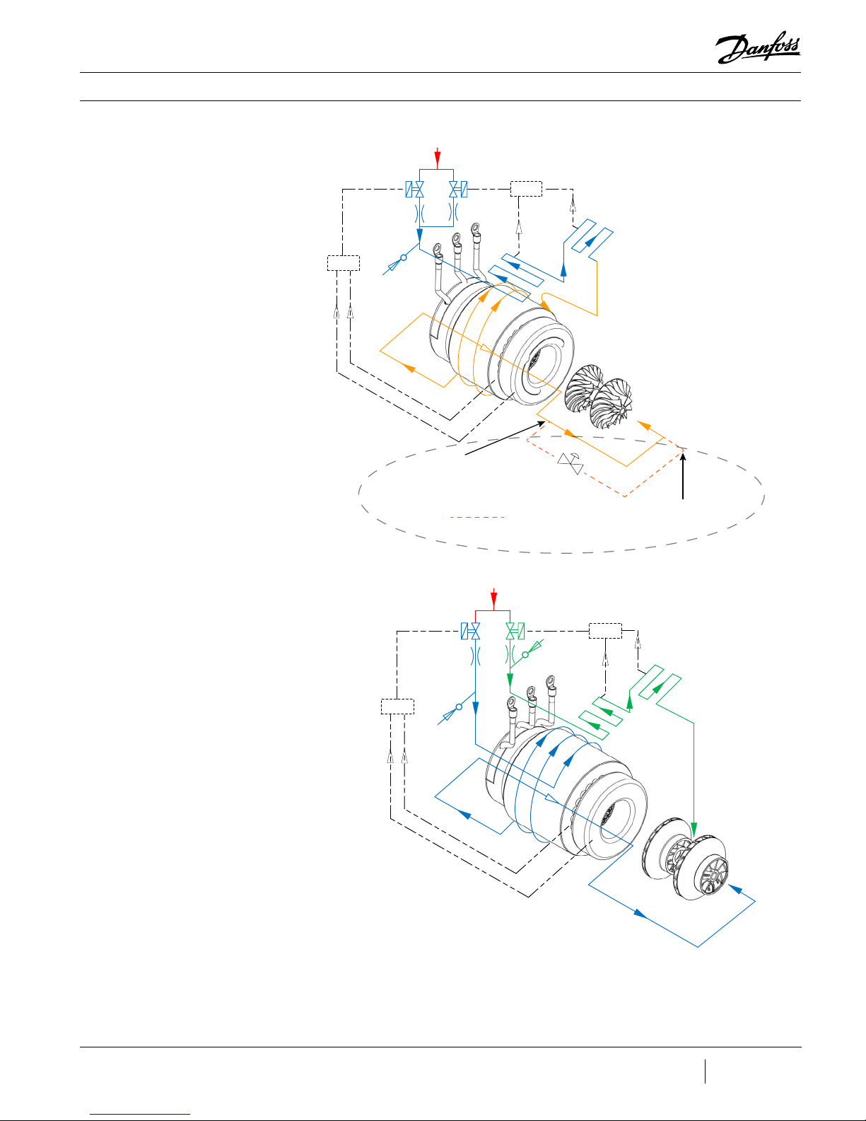
3.1 Main Fluid Path
Figure 3-1 - Compressor
Fluid Path TG230 / TT300
Compressor operation begins with a call for cooling from a chiller controller. The compressor
controller then begins compressor ramp-up.
The following paragraphs describe the ow of refrigerant from the intake to the discharge
port of the compressor (see Figure 3-1 and Figure 3-2).
The refrigerant enters the suction side of the compressor as a low-pressure, lowtemperature, super-heated gas. The refrigerant gas passes through a set of adjustable Inlet
Guide Vanes (IGVs) that are used to control the compressor capacity at low-load conditions.
The rst compression element the gas encounters is the rst-stage impeller. The centrifugal
force produced by the rotating impeller results in an increase in both gas velocity and
pressure. The high-velocity gas discharging from the impeller is directed to the secondstage impeller through de-swirl vanes. The gas is further compressed by the second-stage
impeller and then discharged through a volute via a diuser (a volute is a curved funnel
increasing in area to the discharge port. As the area of the cross-section increases, the volute
reduces the speed of the gas and increases its pressure). From there, the high-pressure/
high-temperature gas exits the compressor at the discharge port.
1st Stage
Impeller
Volute
Assembly
Discharge Port
Low - Pressure / Low Temperature Gas
Inlet Guide Vanes
(IGV)
High - Pressure / High Temperature Gas
2nd Stage Impeller
Vaned
Diffuser
M-AP-001-EN Rev. N
Page 19 of 108
Page 20

Figure 3-2 - Compressor
Fluid Path (TG310, TT350,
TG390, TT400, TG520, and
TT700)
Low - Pressure / Low Temperature Gas
Functional Description
Volute
Assembly
Discharge Port
High - Pressure /
High - Temperature
Gas
2nd Stage Impeller
Inlet Guide Vanes (IGV)
1st Stage Impeller
De-swirl Vanes
Vaneless Diffuser
3.2 Motor Cooling Liquid refrigerant is channelled at full condenser pressure from the main liquid line to the
compressor to cool the electronic, mechanical, and electromechanical components (see
Figure 3-3 and Figure 3-4).
• • • CAUTION • • •
A minimum operating pressure ratio of 1.5 is required to maintain adequate cooling of the compressor.
The sub-cooled refrigerant enters the compressor through two solenoid valves and
associated xed orices located behind the service access cover. The orices cause the
refrigerant to expand, thereby lowering its temperature. Both valves operate relative to the
temperature at the sensors that are located at the Insulated Gate Bipolar Transistor (IGBT)
Inverter and motor cavity. When the temperature at either sensor reaches a pre-determined
threshold, one solenoid valve opens. If the temperature increases to the point where it
equals a higher temperature threshold, the second solenoid valve opens.
From the outlet of the orices, the refrigerant is directed to the heatsink plate of the inverter
and then to the underside of the SCR heatsink. From there, the refrigerant passes through
grooves surrounding the motor stator. As the refrigerant ows through the grooves, it
vaporizes into a gas. At the coil outlet, the refrigerant gas is channeled back to the suction
inlet via the motor cavity, thereby cooling the rotor. All models with the exception of the
TT300 and TG230 use a split-cooling method where the motor and electronics portions are
cooled separately by refrigerant liquid.
Page 20 of 108
M-AP-001-EN Rev. N
Page 21
Functional Description
Figure 3-3 - Compressor
Cooling Circuit (TG230 /
TT300)
From Motor
Winding Temp.
Sensor
BMCC
Solenoid
A
From Motor
Cavity Tem p.
Sensor
Liquid
Refrigerant
Inlet
ORIFICEORIFICE
Cooling path
redirects outside of
the compressor
MT Only
Solenoid
B
IGBT
BMCC
From IGBT
Temp. Sensor
Pressure
Regula�ng
Valve
From SCR
Temp. Sensor
SCR
Motor/Rot or
cooling gas and
leakage
Cooling path re-enters
at the suc�on line of
the chiller
Figure 3-4 - Compressor
Cooling Circuit (TT300
Split-Cooling, TG310, TT350,
TG390, TT400, and TG520)
From Motor
Win ding T emp.
Senso r
BMCC
Solen oid
A
From Motor
Ca vit y Temp .
Senso r
OR IFI CE
Li quid
Refri gerant
Inl et
Solen oid
B
OR IFI CE
Fr om IG BT
Te mp. Sen sor
BMCC
IGB T
From SCR
Te mp. Sen sor
SCR
Motor/Rotor
coo li ng g as a nd
leak age
M-AP-001-EN Rev. N
Page 21 of 108
Page 22
Functional Description
3.3 Inlet Guide Vanes The Inlet Guide Vane (IGV) assembly is a variable-angle guiding device that is used for
capacity control. The IGV assembly consists of movable vanes and a motor. The vane
opening is determined by the BMCC and controlled by the Serial Driver. The IGV position can
vary between 0-110% where 0% is fully closed and 110% is fully open with the vanes at a 90°
angle.
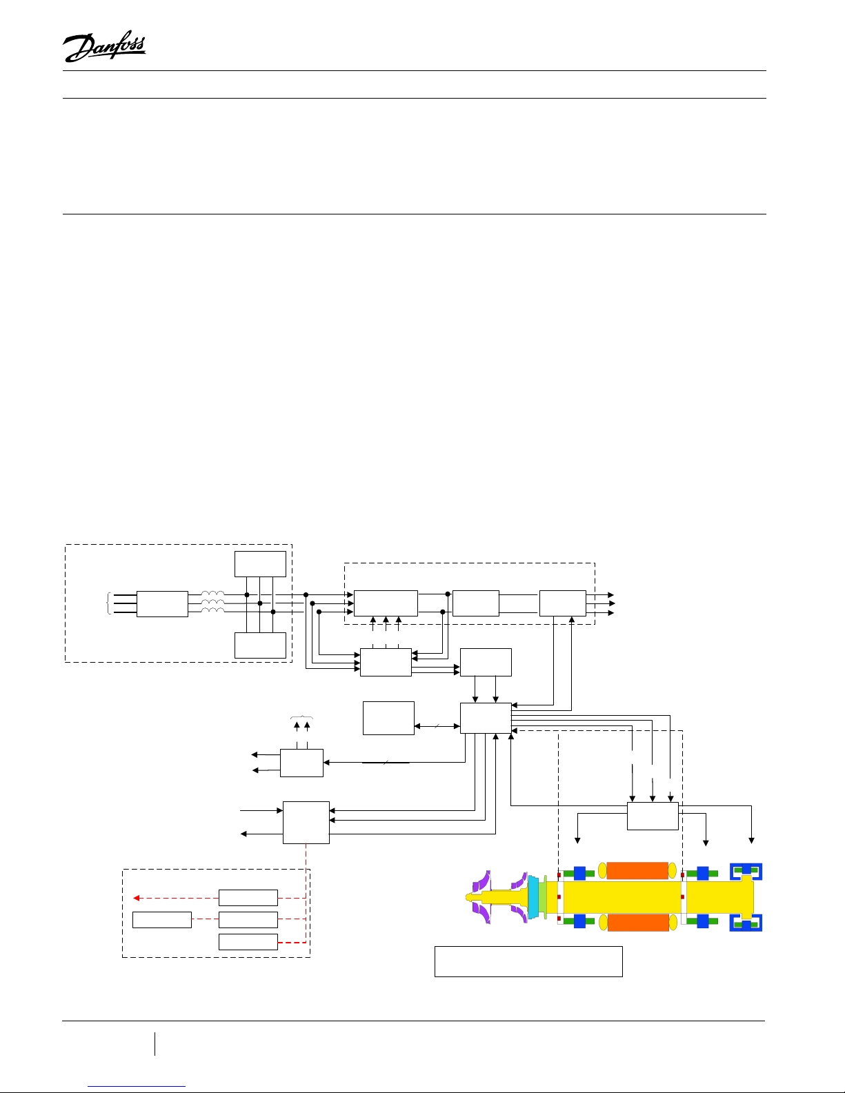
3.4 Compressor Control
Overview
Figure 3-5 - Compressor
Control System Functional
Block Diagram
External Power Components
3-Phas e
380-57 5VAC
50/ 60 Hz
EMI/EMC
Fil ter
To Motor Cooling Solenoids
To IGV St eppe r Motor
RS-485 Comm s
to Chil ler or Buildi ng
Manag ement System
Int erne t
Com pres sor
Com pres sor
Figure 3-5 shows a functional block diagram of the compressor control and monitoring
system. Figure 3-7 displays the component locations. The major components include:
• Motor Drive
• Soft-Start Board
• Bearing Motor Compressor Controller (BMCC)
• Bearing PWM Amplifier
• Backplane
• Serial Driver
• HV DC-DC Converter
Su rge
Lin e
Rea ctor
Inputs
Outputs
Suppresso r
Ha rmoni c
Fil ter
Ex tern al Expa nsi on V al ves
+24V DC
+15V DC
0-10V DC
0-10V DC
Use r I nte rf ace
Cus tome r
Chiller Control
Com mun icati ons
Int erfa ce
Diagnostic
Te rmin al
3-Pha se
380-57 5VAC
50/60 Hz
+15V DC
Seria l
Dri ver
Modu le
Com pres sor
I/O
Boa rd
Half -Controlled
Rec tifie r
0-12 VD C
next (+ ) DC bus
Soft-S tart
Con tro ller
Bear ing
Motor
Com pres sor
Controller
(BMCC)
+15V DC
+24V DC
Con tro l
Fee dbac k
+5 VDC
+15V DC
Con tro l
Fee dbac k
Motor Drive
1.3 5*V
in
0 VDC
460-85 3 VDC
15 V AC
+24V DC
+5 VDC
+15V DC
-15V DC
Con tro l
No te:
All vo ltage leve ls shown have t he foll owin g e rror tol erance:
460-85 3 VDC
DC Li nk
Ca pacit ors
0 VDC
DC/DC
Con ver ter
+
(+250 VDC)
HV
not HV
Backplane
DC (e xce pt the DC bu s): ±5%
AC : ±10 %
Con tro l
Fee dbac k
-
Con tro l
Fee dbac k
3-Phas e
Inv ert er
IGB T
+24V DC
Gat ing
Sign als
Sh aft Posi tion Out puts
2-3A
(Calibration)
Fr ont
Rad ial
Bear ing
V
Freq uency
a
(0-750H z)
V
b
AC Vo ltage
V
c
To Stator
+
HV
not HV
Bea rin g P WM
Varia ble
-
+17V DC
not HV
Amplifier
-
+5 VDC
Rear
Radial
Bear ing
(Calibration)
2-3A
(Calibration)
2-3A
Axial
Bear ing
Page 22 of 108
M-AP-001-EN Rev. N
Page 23

Functional Description
3.4.1 Motor Drive System Normally, AC power to the compressor remains on even when the compressor is in the idle
state. The compressor motor requires a variable-frequency three-phase source for variablespeed operation. The AC line voltage is converted into a DC voltage by Silicon-Controlled
Rectiers (SCRs). DC capacitors at the SCR output serve as energy storage and lter out the
voltage ripple to provide a smooth DC voltage. The Insulated Gate Bipolar Transistor (IGBT)
is an inverter that converts the DC voltage into an adjustable three-phase AC voltage. Pulse
Width Modulation (PWM) signals from the Bearing Motor compressor Controller (BMCC)
control the inverter output frequency and voltage. By modulating the on and o times of
the inverter power switches, three-phase variable sinusoidal waveforms are obtained.
If the power should fail while the compressor is running, the motor switches into generator
mode, thereby sustaining the capacitor charge. The rotor can then spin down safely in a
controlled sequence preventing damage to components.
3.4.2 Soft-Start Board The Soft-Start Board limits inrush current by progressively increasing the conduction angle
of the SCRs. This technique is used at compressor start-up while the DC capacitors are
charging up.
The soft-start function and the variable-speed drive combined limit the inrush current at
startup.
3.4.3 Bearing Motor
Compressor Controller
The hardware and software for the compressor controller and the bearing/motor controller
physically reside in the BMCC. The BMCC is the central processor of the compressor.
3.4.4 Compressor Control The Compressor Controller is continuously updated with critical data from external sensors
that indicate the compressor’s operating status. Under program control, the compressor
controller can respond to changing conditions and requirements to ensure optimum system
performance.
Figures 3-5 to Figure 3-7 shows how the controller responds to chiller demands.
3.4.5 Capacity Control One of the Compressor Controller’s primary functions is to control the compressor’s motor
speed and IGV position in order to satisfy load requirements and to avoid surge and choke
conditions. However, the majority of capacity control can be achieved via motor speed.
M-AP-001-EN Rev. N
Page 23 of 108
Page 24

Functional Description
3.4.6 Expansion Valve
Control
3.4.7 Motor/Bearing
Control
3.4.8 Monitoring
Functions
The on-board Electronic Expansion Valve (EXV) driver uses manual control only.
Depending on the application, a load balancing (hot gas bypass) valve can be manually
driven by the auxiliary EXV output. Load balancing allows the compressor to obtain lower
capacities at higher pressure ratios. The valve opens to lower the overall pressure ratio and
thereby reduces the lift, enabling the compressor to reduce speed/unload.
The magnetic bearing system physically supports a rotating shaft while enabling noncontact between the shaft and surrounding stationary surfaces. A digital bearing controller
and motor controller provide the PWM command signals to the Bearing PWM Amplier and
IGBT Inverter, respectively. The bearing controller also collects shaft position inputs from
sensors and uses the feedback to calculate and maintain the desired shaft position.
The compressor controller monitors more than 60 parameters, including:
• Gas pressure and temperature monitoring
• Line voltage monitoring and phase failure detection
• Motor temperature
• Line currents
3.4.9 Abnormal
Conditions
• External interlock
The compressor controller responds to abnormal conditions by monitoring:
• Surge RPMs
• Choke RPMs
• Power failure/phase unbalance
• Low/high ambient temperature
• High discharge pressure
• Low suction pressure
• Motor-cooling circuit failure (over temperature)
• Refrigerant loss
• Power supply
• Overcurrent
Page 24 of 108
M-AP-001-EN Rev. N
Page 25

Functional Description
3.4.10 Bearing PWM
Amplier
3.4.11 Serial Driver
3.4.12 Backplane
The Bearing PWM Amplier supplies current to the radial and axial magnetic bearing
actuators.
The PWM Amplier consists of high-voltage switches that are turned on and o at a high
frequency, as commanded by the PWM signal from the BMCC.
The Serial Driver module performs serial-to-parallel conversion on the stepper motor drive
signals from the BMCC. The module also contains four normally open relays under BMCC
control. Two of the relays drive the motor-cooling solenoids, and the other two are used
to indicate compressor fault status and running status. The status relays can be wired to
external control circuits.
The Backplane physically interconnects the on-board plug-in modules with the power
electronics, IGV stepper motor, motor-cooling solenoids, rotor position sensors, and
pressure/temperature sensors. The Backplane also features on-board, low-voltage DCDC converters for generating +15V, -15V, +5V, and +17V from an input of +24VDC. The
Backplane receives its +24VDC power input from the High-Voltage (HV) DC-DC Converter
mounted on the topside of the compressor.
The Backplane is also equipped with status-indicating LEDs. All LEDs are yellow except for
the alarm LED, which is green/red. Table 3-1 Backplane LEDs describes the LEDs functions.
Table 3-1 - Backplane LEDs
LED Function
+5V, +15V, +17HV,
+24V
Cool -H, Cool -L LEDs are lighted when their respective coil is energized.
Run LED is lighted when the shaft is spinning.
Alarm LED is green when in normal status, red when in alarm status.
D13, D14, D15, D16 LEDs indicate IGV status and ash when IGV is moving.
LEDs are lighted when DC power is available.
M-AP-001-EN Rev. N
Page 25 of 108
Page 26

Functional Description
3.4.13 High-Voltage DCDC Converter
3.5 Magnetic Bearing
System
3.5.1 Overview
Figure 3-6 - Magnetic
Bearing Conguration
DC-DC converters supply and electrically isolate the high and low DC voltages that are
required by the control circuits. The HV DC-DC Converter delivers 24VDC and 250VDC from
an input of 460-900VDC. The 24VDC and 250VDC are used to power the Backplane and
magnetic bearing PWM Amplier, respectively.
A rotating shaft, under changing load conditions, will experience forces in both radial and
axial directions. In order to compensate for these forces, a ve-axis bearing system is used,
incorporating two radial bearings of two axes each, and one thrust (axial) bearing (see
Figure 3-6).
3.5.2 Bearing Control
System
The Bearing Control System uses rotor position feedback to close the loop and maintain the
rotor in the correct running position (see Figure 3-7). The Bearing Controller issues position
commands to the Bearing PWM Amplier. The position commands consist of ve channels
with each channel allocated to one of the ve bearing actuator coils (one coil for each axis).
The amplier uses IGBT technology to convert the low-voltage position commands to the
250VDC PWM signals that are applied to each bearing actuator coil.
Rotor position sensors are located on rings attached to the front and rear radial bearing
assemblies. The front sensor ring contains sensors that read the rotor position along the X,
Y, and Z axes. The rotor position along the Z (or axial) axis is read by measuring the distance
between the sensor and a target sleeve mounted on the rotor. The rear sensor ring contains
sensors that read the position along the X and Y axes. Information from the position sensors
is continuously fed back to the bearing controller.
Page 26 of 108
M-AP-001-EN Rev. N
Page 27
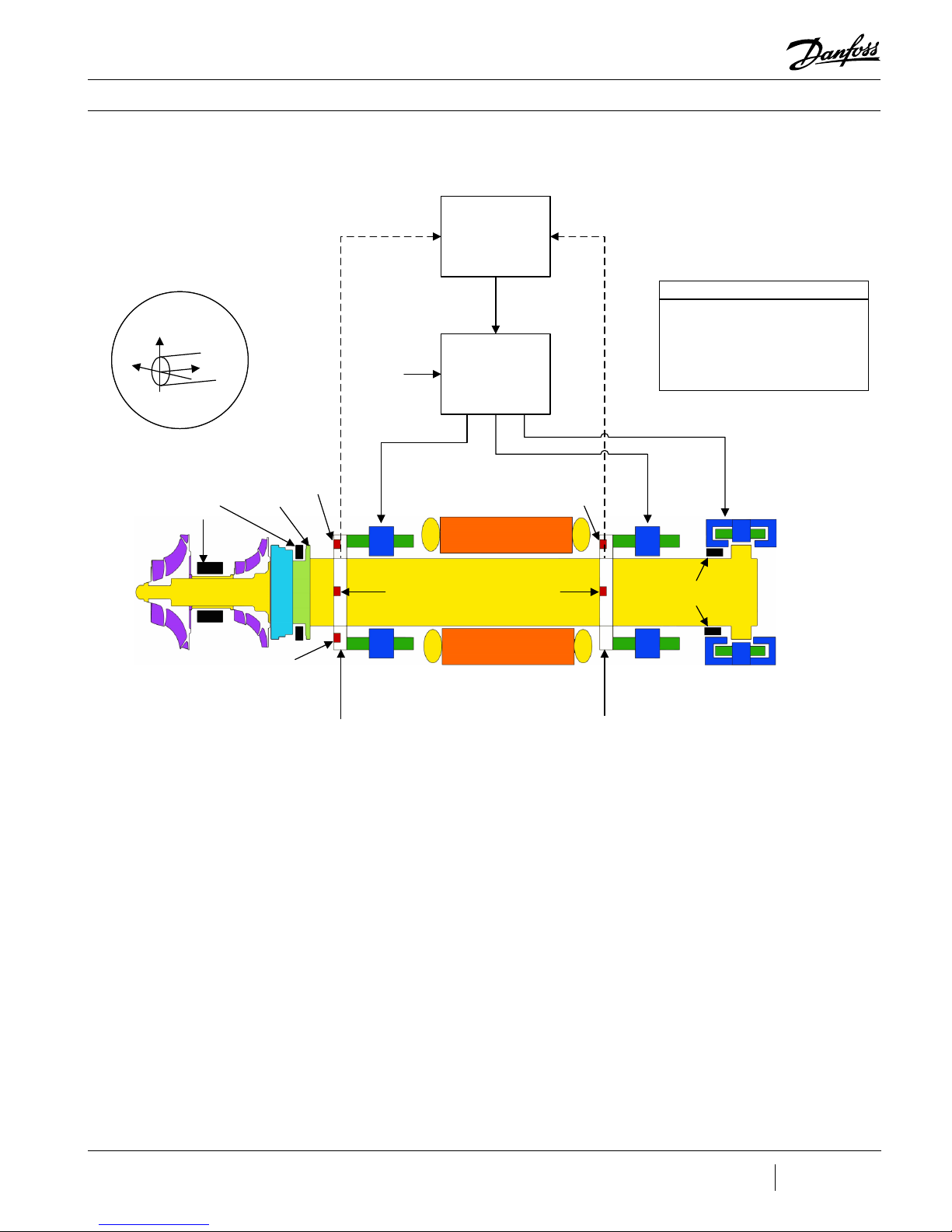
Figure 3-7 - Magnetic
Axi s Be ari ng Channel
X Front Radi al Fx
Y Front Radial Fy
X Rear Radial Rx
Y Rear Radial Ry
Z Axi al Axi
Channel Assignment s
Bearing Control System
Functional Description
Y
Y
Shaft
X
X
Shaft
Z
Z
Shaft axes monitored
by position sensors
Touc hdown
Bearings
Impellers
Target
Sleev e
Y-axis
Po siti on
S ensor
Z-axis
Po siti on
S ensor
S ensor Ring
Posi tion Comm and
250 VDC
Channels
Fx, Fy
X-ax is
Po siti on
S ensor
Front
Radia l
Bearing
Bearing-Mo tor-
Co mpr essor
Controlle r (BMCC)
Signals
Bearing
PWM
Amplifier
Motor
X-axis
Po siti on
S ensor
Position FeedbackPosition Feedback
Y-axis
Po siti on
S ensor
S ensor Ring
Channels
Rx, Ry
Touc hdown
Bearings
R ear
Radia l
Bearing
Channel Axi
Axial
Bearing
M-AP-001-EN Rev. N
Page 27 of 108
Page 28

Control Interface Wiring
4 Control Interface Wiring
Figure 4-1 - Typical Control
Wiring
EXV #1
(Evaporator or
load balancing
valve)
EXV #2
(Economizer or
load balancing
valve)
Level
Sensor
#1 (Evaporator)
Level
Sensor
#2 (Economizer)
Temperature Sensor Signal, 1-5Volts
Pressure Sensor Signal, 1-5Volts
EXV Phase 1A
EXV Phase 1B
EXV Phase 2A
EXV Phase 2B
EXV Phase 1A
EXV Phase 1B
EXV Phase 2A
EXV Phase 2B
Level Sensor +15V
Sensor Signal , 1-5Volts
Level Sensor 0V
Level Sensor +15V
Sensor Signal , 1-5Volts
Level Sensor 0V
The Compressor I/O Board is the entry point for control wiring from the chiller/plant to the
compressor. Refer to Figures 4-1 and 4-2 for the proper Compressor I/O Board connectivity.
RS232 Monitoring Connector (DB9)
1A 1B 2A 2B 1A 1B 2A 2B
EXV1
EXV2
J4 J5
J6
Float
Float
SPARE T SPARE P
DEMAND
J7
STATUSI/LOCK
SPEED
LIQDT
RUN
ANALOG
ENTRY LEAVE
J8
COM
NETB
NETA
J1
OUT
I/O
I/O
IN
IN
IN
IN
OUT
OUT
OUT
OUT
IN
J2
IN
OUT
OUT
OUT
OUT
IN
IN
IN
J3
IN
ModBus Common (Shield)
ModBus RS-485 NetB
ModBus RS-485 NetA
Demand + 0-10V
Demand -
Interlock Contact - Safety N/C
Interlock Contact - Safety N/C
Compressor Status - N/O Contact
Compressor Status - N/O Contact
No function
No function
Liquid Temperature +
Liquid Temperature -
Compressor Running - N/O Contact
Compressor Running - N/O Contact
*Universal Analog Output +
*Universal Analog Output -
Entering Chilled Water
Temp. Sensor
Leaving Chilled Water
Temp. Sensor
Sensor 0V
Sensor +5V
OUT
OUT
OUT
OUT
OUT
OUT
OUT
OUT
OUT
IN
OUT
OUT
IN
OUT
IN
OUT
OUT
IN
**Level sensor circuit can be congured
for two types of sensors using jumpers
JP5 and JP6. Refer to the Installation and
Operations Manual for details.
Figure 4-2 - ModBus
Grounding Diagram
Page 28 of 108
Retain
Termination
Jumper in
Last Board
REF
+
-
RS485-1
Shield
I-Lock
CIM Board
M-AP-001-EN Rev. N
REF
+
RS485-1
Shield
I-Lock
CIM Board
-
Remove Termination
Jumper in All
Intermediate Boards
REF
+
RS485-1
Shield
I-Lock
CIM Board
* Universal output can be used for :
output manual control
0-5VDC or 0-10VDC
COM NETB NETA
MODBUS
REF
-
-
+
120Ω
PLC
Termination Resistor should only be included
if one is not included in the PLC. If the PLC
has a resistor installed, do not add an addi-
tional one. If the PLC does not have a resistor
installed, then one should be installed.
Page 29

Control Interface Wiring
Table 4-1 - Control Wiring
Details
I/O Description
COM (shield) Shield for RS-485 communication
Modbus RS-485 NetB/NetA Modbus over RS-485 communication port
Stepper Motor 1 Phase 1A, 1B, 2A,
2B and
Stepper Motor Phase 1A, 1B, 2A,
2B
Level Sensor +15V (Evaporator) Power supply for level sensor #1
Sensor Signal (Evaporator) Input from a level sensor to control the main expansion valve (evaporator)
Level Sensor +15V (Economizer) Power supply for level sensor #2
Sensor Signal (Economizer)
Demand 0 - 10V
Interlock
Status
Liquid Temperature
Run
Analog
Entering Chilled Water Temp
Leaving Chilled Water Temp
Spare T +/-
Spare P +/- Can be connected to a 0-5V type pressure sensor
Optional output connections for controlling the main electronic expansion
valve (evaporator) or auxillary electronic expansion valve (economizer or load
balancing valve). 200ma Maximum output on each driver. Valve frequency
will eect operational characteristics.
Input from a level sensor to control the auxiliary expansion valve
(economizer)
Analog input from customer-supplied controller to drive the compressor, i.e.,
0 - max. kW input with a deadband of 2VDC for the respective compressor
model. Only available in 3.1.4; removed in 4.x forward.
Connects to a set of external normally closed contacts that typically open in
the event of loss of chilled water or air ow. Typically a 1.5VDC Output signal.
NOTE: This is not a safety certied interlock.
An internal normally open contact that is closed during normal operation
and opens in the event of a compressor fault. With the circuit open, the
compressor will not restart until the demand signal has been reset to 0 (via
chiller/unit controller). Circuit rated at 1A @ 30VDC/24VAC or .03A @ 120VAC.
Optional input for monitoring temperature. The temperature sensor must be
an NTC type 10K @ 25°C thermistor.
An internal N/O contact that is closed while the compressor is running.
The speed at which the contact closes is user-congurable via the monitor
program. Circuit rated at 1A @ 30VDC/24VAC or 0.3A @ 120VAC.
Universal analog output manually controlled as a percentage of total voltage
written through Modbus. This can be congured for 0-5V or 0-10V via on
board jumpers.
Analog input indicating water temperature. The temperature sensor must
be an NTC type 10K @ 25°C thermistor. Refer to Application Manual for
thermistor specication.
Analog input indicating water temperature. The temperature sensor must
be an NTC type 10K @ 25°C thermistor. Refer to Application Manual for
thermistor specication.
Optional input for monitoring temperature. The temperature sensor must be
an NTC type 10K @ 25°C thermistor.
4.1 Control Wiring
To ensure proper control wiring techniques, follow these guidelines:
Connection Guidelines
1. The ground reference of the external circuit connected to the Compressor I/O Board
2. The Interlock circuit should be voltage-free. For instance, all external contractors/
3. Analog outputs (such as Motor Speed) must be received by the external circuit without
4. All interlock and analog output cables should be shielded with one end of the shield
must be at the same potential as the ground reference on the Compressor I/O Board.
switches must not introduce current into the circuit.
sending current back to the Compressor I/O Board.
connected to the common analog or digital ground bus. The other end of the shield
must not be grounded as this would create a ground loop. Refer to Figure 4-2.
M-AP-001-EN Rev. N
Page 29 of 108
Page 30

Control Interface Wiring
4.2 Interface Cable
Figure 4-3 - I/O Wiring
Specications
The cable that carries the I/O communication to the compressor is 5 meters (16.4 feet) in
length and is equipped with high-density 44-pin connectors (female at one end and male at
the other end). An extension cable is available from your local supplier. An optional 10 meter
(32.8 ft) cable is also available in the Spare Parts Selection Guide.
NOTE
If an I/O extension cable is used, heat-shrink tubing should be applied to the mating cable connectors to maintain good
conductivity and protect the connection from heat and humidity.
For RS-485 communication, the maximum cable length should not exceed 100 meters (328
feet). If using RS-232 communication, the cable length should not exceed 15 meters (50 feet)
between the PC and the compressor (refer to Figure 4-3).
Page 30 of 108
M-AP-001-EN Rev. N
Page 31

Control Interface Wiring
4.3 Compressor I/O Board
Mounting Details
Figure 4-4 - Compressor I/O
Board
The Compressor I/O Board (Figure 4-4) must be installed in a UL-approved electrical
enclosure equipped with DIN EN 50022, 50035, or 50045 mounting rails. The board should
be mounted in a dry area free from vibration and electrical noise.
NOTE
The UL listed enclosure should protect against moisture and other corrosive elements.
4.3.1 Compressor
I/O Board - Mounting
Instructions
Figure 4-5 - Compressor I/O
Board Installation
1. Tilt the I/O Board as shown in Figure 4-5 in order to engage it into the DIN Rail.
2. Lower the I/O Board until it snaps into place.
M-AP-001-EN Rev. N
Page 31 of 108
Page 32

THIS PAGE INTENTIONALLY LEFT BLANK
Page 32 of 108
M-AP-001-EN Rev. N
Page 33

5 General Specifications
General Specications
5.1 Construction
5.2 Maximum Pressure
Table 5-1 - Discharge
Pressure Alarm and Trip
Settings
• Compressor - Semi-hermetic design
• Main Housing - Dimensionally-stabilized aluminum
• Covers - High-impact, UV stabilized, flame-resistant polymer.
• Covers - High-impact, UV stabilized, flame- resistant polymer. TG series is identified
by green cover.
• Shaft - High-strength alloy
• Impellers - High-strength aluminum
• Motor - Permanent magnet, synchronous, DC
• Bearings - Integrated, digitally-controlled, magnetic
• Compressor Control - Integrated, digital capacity control
• Enclosure - IP54 rating as per UL 984 requirement
The maximum pressure that the compressor can operate is regulated directly by two control
settings: (1) Alarm Limit and (2) Trip Limit. It is also controlled by a Pressure Ratio alarm limit
monitoring the ratio between the Discharge and Suction Pressures.
Alarm Trip
Model kPa(g) PSIG kPa(g) PSIG
TG230ST* 1239 180 1299 188
TG230MT* 1116 162 1176 171
TG310 1240 180 1300 189
TG390 876 127 926 134
TG520 876 127 926 134
TT300ST* 1190 173 1240 180
TT300MT* 1190 173 1240 180
TT350 1730 251 1800 261
TT400 1190 173 1240 180
TT700 1190 173 1240 180
* The TG230/TT300 compressors, the alarm and trip settings are default to lower values of operation which are
typcially deemed appropriate for Water-Cooled condiitons.
These values allow for adjustment for compressors placed in Air-Cooled applications which can have the value
increased up to 1730 kPa(g)/250 PSIG for the Alarm and 1800 kPa(g)/260 PSIG for the Trip.
M-AP-001-EN Rev. N
Page 33 of 108
Page 34

General Specifications
5.3 Maximum Discharge
Temperature
Table 5-2 - Discharge
Temperature Trip Settings
Unit Compressor TG230 ST TG230 MT TG310 ST TG390 ST TG520 ST TT300 ST TT300 MT TT350 ST TT400 ST TT700 ST
°F Trip 212 194 203 194 194 212 194 203 194 194
°C Trip 100 90 95 90 90 100 90 95 90 90
Table 5-3 - Maximum
Pressure Ratio Limits
Compressor TG230 ST* TG230 MT* TG310 ST TG390 ST TG520 ST TT300 ST* TT300 MT* T T350 ST TT400 ST TT700 ST
The maximum temperature that the compressor can operate is regulated directly by the Trip
Limit.
The Maximum Discharge Temperature Limits are dened in Table 5-2.
NOTE
While the values here are represented in Gauge Pressure, the values in the registers will be dened in Absolute Pressure. Refer
to the OEM Programming Guide to identify the specic registers associated with the Discharge Pressure Alarm and Discharge
Pressure Trip Limits.
The compressor will also adjust its operation if the pressure ratio exceeds the alarm limit.
The Pressure Ratio alarm limit is dened in Table 5-3.
Alarm 4 4 5.2 3.5 3.5 4 4 5.2 3.5 3.5
Trip 5.2 5.2 5.5 4 4 5.2 5.2 5.5 4 4
Table 5-4 - Maximum
Allowable Pressure [PS]
*The TG230/TT300 compressor allows for adjustment of this setting.
Compressors which are placed in Air-Cooled applications can have this value increased up to 4.8.
NOTE
Pressure ratio must be calculated using absolute pressures. Refer to the OEM Programming Guide to identify the specic register
associated with the Pressure Ratio Alarm Limit.
Beyond these control limits, the Maximum Design High-Side Pressure for the compressor is
shown in Table 5-4.
Unit
kPag 2070
psig 300
ALL
MODELS
Page 34 of 108
M-AP-001-EN Rev. N
Page 35

General Specications
The Suction Pressure alarm and trip limits are displayed in the Table 5-5.5.4 Suction Pressure
Limits
Table 5-5 - Suction Pressure
Alarm and Trip Settings
Alarm Trip
Model kPa(g) PSIG kPa(g) PSIG
TG230ST 99 14 79 11
TG230MT 40 6 29 4
TG310 99 14 79 11
TG390 99 14 96 14
TG520 99 14 96 14
TT300ST 177 26 152 22
TT300MT 91 13 76 11
TT350 177 26 152 22
TT400 177 26 166 24
TT700 177 26 166 24
Pressure ratio is the ratio of absolute discharge to absolute suction pressure. It can be calculated as follows:
• (DP + 101) / (SP + 101) (kPa) OR
• (DP + 14.7) / (SP + 14.7) (psi)
5.5 Codes and Standards
Compliance
NOTE
• TT and TG Series Turbocor Compressors were designed for use in stationary
building applications.
• An OEMs use of Turbocor Compressors in applications other than stationary
building applications (e.g. Marine Applications) is considered a non-standard
application and is not eligible for warranty under DTCs standard warranty Terms
and Conditions.
It is the responsibility of the OEM to ensure that proper safety protocols are in place and that
the chiller system has been designed in a manner that is compliant with all local codes and
regulatory requirements governing the use of refrigerants, pressure, vessels, and electrical
power. OEMs must also ensure compliance with the requirements stated in the refrigerant
manufacturer’s Material Safety Data Sheet (MSDS) and that other system components are
compatible with the refrigerant, giving special attention to elastomers and seals.
M-AP-001-EN Rev. N
Page 35 of 108
Page 36

THIS PAGE INTENTIONALLY LEFT BLANK
Page 36 of 108
M-AP-001-EN Rev. N
Page 37

6 Electrical Specifications
Electrical Specications
6.1 Supply Voltage and
Frequency
Table 6-1 - Acceptable AC
Voltage Range
Table 6-2 - Acceptable
Frequency Range
Turbocor compressors are designed to operate with a power supply that is within an
acceptable tolerance for each nominally rated voltage and frequency. The tables below
specify the acceptable supply voltage and frequency ranges. Using a supply voltage/
frequency at or beyond the range limit will cause the compressor to shut down.
Nominal Voltage Acceptable Voltage Range
380V 342 - 418 VAC
400V 360 - 440 VAC
460V 414 - 506 VAC
575V 518 - 635 VAC
• • • CAUTION • • •
Application of a compressor to any voltage which is outside of the nominal rated voltage dened on the compressor
nameplate will result in voiding of the compressor warranty from DTC, unless otherwise stated by DTC. This includes any
application of a 400V compressor in a 380V application without the use of a transformer to correct the voltage going into the
compressor.
NOTE
Refer to the TT/TG Compressor Nomenclature section of this manual for details on the compressor voltage availability.
Nominal Frequency Acceptable Frequency Range
50Hz 50Hz ±5% (47Hz - 53Hz)
60Hz 60Hz ±5% (57Hz - 63Hz)
6.2 Compressor Current
Limit and Operating
Range Settings
The new compressor controller (version 3.0.0 and above; see Section 1.1 “Scope”) is
designed to allow a user to congure the current setting based on the intended application.
The compressor denes the Full Load Amperage (FLA) and Locked Rotor Amperage (LRA) as
a range on the nameplate. The settings for the FLA and LRA are adjustable using the Service
Monitoring Tool (SMT) or directly from the customer controller application.
The 3-Phase Over Current Alarm (FLA) cannot be set higher than the 3-Phase Over-Current
Fault limit (LRA). The maximum fault limit and alarm limit settings are dependent upon the
Voltage and Model. The Model type denes the range for the FLA and LRA values.
M-AP-001-EN Rev. N
Page 37 of 108
Page 38

Electrical Specications
Table 6-3 - FLA and LRA
Value Range
Model Voltage
TG230 380V 40 106 44 117 40 44
TG230 400V 40 106 44 117 40 44
TG230 460V 40 99 44 110 40 44
TG230 575V 40 79 44 88 40 44
TG310 380V 50 150 55 165 50 55
TG310 400V 50 150 55 165 50 55
TG310 460V 50 135 55 145 50 55
TG390 380V 50 123 55 137 50 55
TG390 400V 50 123 55 137 50 55
TG390 460V 50 108 55 120 50 55
TG390 575V 50 86 55 96 50 55
TG520 380V 50 149 55 165 50 55
TG520 400V 50 142 55 158 50 55
TG520 460V 50 123 55 137 50 55
TT300 380V 40 145 44 160 40 44
TT300 400V 40 145 44 160 40 44
TT300 460V 40 135 44 150 40 44
TT300 575V 40 110 44 121 40 44
TT350 380V 50 210 55 231 50 55
TT350 400V 50 210 55 231 50 55
TT350 460V 50 180 55 198 50 55
TT400 380V 60 170 66 187 60 66
TT400 400V 60 170 66 187 60 66
TT400 460V 60 150 66 165 60 66
TT400 575V 60 120 66 132 60 66
TT700 380V 60 206 66 227 60 66
TT700 400V 60 196 66 216 60 66
TT700 460V 60 170 66 187 60 66
FLA LRA Default
Min Max* Min Max FLA LRA
6.3 Disconnects
NOTE
Refer to the OEM Programming Guide to identify specic registers associated with the “3-Phase Over Current Alarm (FLA) and
3-Phase Over Current Fault (LRA).”
An input disconnect (for example, a switch or circuit breaker) must be installed in the line
before the compressor in accordance with applicable local, national, and international codes
(for example, NEC/CEC). Size the disconnect according to the full-load current.
• • • CAUTION • • •
The full-load current rating is based on the installation of a line reactor in the power line. Refer to the Spare Parts Selection Guide
for specications. Failure to use a line reactor will result in poor power factor and higher full-load current.
Refer to Figure 20-9 for interconnection details.
Page 38 of 108
M-AP-001-EN Rev. N
Page 39

Electrical Specications
6.4 Motor Insulation Class All TT/TG Series compressors have a motor insulation Class H rating or better according to
the NEMA/UL Standard.
6.5 AC Input Line/Power
Electronic Component
Protection
Most codes require that upstream branch protection be provided to protect input power
wiring personnel and switching equipment from damage in the event of an over current
condition or equipment failure. Standard fuses and/ or circuit breakers do not provide
adequate protection for the compressor’s power electronics components.
User-supplied, properly sized and selected fast-acting fuses must be installed according to
the applicable local, national, and international codes. The fuses must be installed in the line
before each compressor’s AC input terminals.
Use only properly rated fast-acting line fuses suitable for semiconductor protection, such as
Littelfuse JLLS series, Siemens Sitor 3NE1 series, or equivalent.
• • • DANGER • • •
Fast-acting fuses are only for the purpose of reducing the accumulated energy in a compressor’s power electronics caused by a
short circuit event. Properly sized and selected fast acting fuses must be installed.
Sub-circuit protection must be considered separately in accordance with local electrical requirements.
User-supplied branch circuit protection must be installed in accordance with local, national, and international codes (such as NEC/
CEC). The fuses must be installed in the line before the compressor’s AC input terminals.
NOTE
Fuse selection must be done using the Full Load Amps (FLA) of the aected compressor to the next highest amp, but in any
event should be a minimum of FLA x 1.25. Fast acting fuses must be installed as close as possible and immediately before the
compressor; that is downstream from the line reactor. (Contact DTC for more information).
6.6 Power Line Contactor
6.7 CE Compliance and
EMI/EMC Filtering
The power line contactor is optional. Consult local codes to determine if a contactor is
necessary for your application.
To address EMI/EMC problems, DTC recommends the installation of a UL-approved EMI/EMC
lter device on the input power line. Refer to the Spare Parts Manual for details.
Although all Turbocor compressors are CE listed, the compliance of the compressor with the
EMC directive depends on the use of the CE EMI/EMC lter provided by DTC (see Accessories
Manual for further details). If this is not possible because of the nature of your application
and/or installation, an alternative component with the same attenuation characteristics
must be used to maintain compliance with the EMC Directive. It is the responsibility of the
user to maintain compliance with the Directives. Contact a DTC sales representative for
more details.
Proper installation of the EMI/EMC lter can have a dramatic eect on overall performance.
Although the lter reduces electrical noise on the power lines (conducted emissions), it
should be located as close as possible to the compressor to reduce broadcasting of the
noise (radiated emissions) from the power lines themselves. The capacitors within the lter
short the noise to ground so it is imperative that the lter maintains a good ground. A short,
heavy, stranded conductor from the lter chassis to the main ground bus is recommended
for top performance. A battery braid, litz wire, or exible welding cable with many ne
M-AP-001-EN Rev. N
Page 39 of 108
Page 40

Electrical Specications
strands, is recommended for best grounding performance. The multiple-strand cabling
provides more surface area in order to conduct the high frequencies that are on the
grounding cable.
Radiation of noise is also a concern for power line routing as it can eectively bypass the
lter. Input and output lter leads should be separated by a maximum practical distance
within enclosures and should be routed separately in interconnecting conduits when used.
NOTE
All TT compressors are compliant with standards:
2004/95/EC
2006/42/EC
IEC 60335-2-34:2002
IEC 60335-1:2007
EN 61000-6-2:2005
EN 61000-6-4:2007
6.8 Surge Protection
6.9 Harmonic Filtering
(IEEE 519)
6.10 Grounding (Earth)
Connection Guidelines
All Turbocor compressors have been tested in accordance with IEC Standard 1000-4-4.
Electrical Fast Transient/Burst Requirement. For additional protection, a surge suppressor
can be installed in parallel with the compressor. It is recommended to install surge
suppression in sites that are susceptible to lighting.
If it is necessary to provide additional harmonic reduction beyond that provided by the
standard 5% line reactor, DTC recommends the installation of a harmonic lter device in
parallel with the compressor as shown in Figure 20-9.
1. All metal parts should be connected to ground, including the shields of electrical
cables.
2. Verify continuity of all ground connections.
3. Ensure solid ground connections (both mechanical and electrical). Connections must
be clean, and grease and paint free.
4. At one point, usually the entrance of the power supply panel, all grounds should be
connected together (refer to Section 6.11).
From an EMC standpoint, it is best to categorize dierent types of grounds and treat them
independently (see Figure 6-1):
• Safety ground (Protective Earth [PE]) and shields of mains cables.
• Analog grounds, shielding of interface cables.
• Digital grounds.
• Reference ground (panel doors, backplate, etc.).
Page 40 of 108
M-AP-001-EN Rev. N
Page 41

Figure 6-1 - Typical Ground
Connections
Electrical Specications
6.11 Equipment Panel
Normally, the line reactor, EMI/EMC lter(s), and the harmonic lter will be installed in a
panel. This could be the same panel where the controls are located. When designing a panel,
attention should be given to the following recommendations:
• All metal parts should be properly connected to ensure an electrical connection.
Connect panel doors with braided cable.
• Separate panel into sections for power and interface/control functions (all
electrical components and practices should follow all applicable local codes and
standards).
• Keep power cables and interface cables separate. Use metal cable glands for
shielded cables.
• The wire-loom going to the panel door should be shielded using a metal-braided
hose that is connected to ground at both ends.
• Electrical panel must have a dedicated ground conductor in accordance with
relevant electrical codes.
• Verify that the panel ground conductor is sized in accordance with relevant
electrical codes.
NOTE
The installing electrical contractor is responsible for connecting the panel ground to the facility ground in accordance with
relevant electrical codes and standards, such as NEC Section 250 in the U.S. or its equivalent for other countries.
Special ltering and measuring may be required in installations such as hospitals that are prone to being inuenced by other
electronic equipment.
M-AP-001-EN Rev. N
Page 41 of 108
Page 42

Electrical Specications
6.12 Mains Input Cable
Specication
Table 6-4 - Main Cable
Connector Plate Hole Sizes
The aim of electrical cables is to be a carrier (conductor) for electrical power. The inuence
of the power source on the environment, or the inuence of the environment on the
power source, should be such that neither the proper functioning of the compressor nor
equipment in its environment is adversely aected. Therefore, DTC advises to use some type
of shielded cable for the mains input.
When using shielded cable, select a cable with an eective shield. A cable with an aluminum
foil will be far less eective than a specially designed conductive braid. It is best to connect
both ends of the cable shield to ground since the shield is not part of the signal path.
Alternatively, non-shielded conductors may be used if they are carried inside of a code
approved electrical metallic conduit of the exible or rigid types.
The mains input cable should be CSA, UL, or CE approved, three-wire with a common shield
and single ground. The cable must be rated for 90°C (194°F) minimum at the maximum
applicable current. It is recommended that the cable be double-jacketed, i.e., teck cable
type. Refer to Table 6-4 for cable gland specications.
Model 380V 400V 460V 575V
TT300/TG230 2.5” 2.5” 2.5” 2.5”
TT350/TG310 2.5” 2.5” 3” N/A
TT400/TG390 2.5” 2.5” 3” 3”
TT700/TG520 2.5” 2.5” 3” N/A
6.13 Idle Power
Consumption
NOTE
The plate hole sizes shown in Table 6-4 are standard production sizes. OEMs have the exibility to change those sizes according
to their needs. Please refer to the Spare Parts Selection Guide for more information on available sizes or contact your Key Account
Manager for possible changes.
TT/TG series have an Idle power consumption of 45 W.
Page 42 of 108
M-AP-001-EN Rev. N
Page 43

7 Compressor Performance
Compressor Performance
7.1 Performance Ratings
7.2 Tolerance of
Performance Ratings
Compressor performance, including applicable capacity range, varies based on the
operating conditions. The capacity range, eciency, and other operational information for
each compressor can be determined only by using the authorized software known as the
“Compressor Performance Rating Engine” or “CPR Engine”. This software and a selection tool
is available on our website.
All TT and TG compressors are guaranteed to meet the published performance ratings in our
CPR Engine within ±5% for capacity, eciency, and power for given operating conditions.
This tolerance band is valid for the area of the operating map which is in the speed control
range only. As the compressor reduces speed and mechanical unloading is enabled such as
the closing of the variable IGV, the tolerance increases to ±10%.
The conditions considered are only the ange-to-ange conditions seen at the compressor
rather than the conditions seen at other points in the system.
The compressor performance ratings are based on using R-134a for the TT series
compressors and R-1234ze for the TG series compressors. The use of alternative refrigerants
in these compressors may lead to variances in the performance. When using refrigerant
R-513A, the tolerance rating is increased by an additional 1.5% so that it is ±6.5% in the
speed control range and 11.5% in the area where mechanical unloading is enabled.
M-AP-001-EN Rev. N
Page 43 of 108
Page 44

THIS PAGE INTENTIONALLY LEFT BLANK
Page 44 of 108
M-AP-001-EN Rev. N
Page 45

8 Operating Envelopes
Operating Envelopes
Figure 8-1 - Operating
Envelope, T T300 and TG230
(1)
NOTE
The maximum Saturated Discharge Temperature (SDT) of the operating envelope represents the limit for compressors with
maximum FLA settings. The SDT for a compressor with a lower maximum current rating is lower than that shown and is related to
the FLA rating of the particular compressor.
The lower limit is related to minimum pressure ratios required to eect proper motor and power electronics cooling with standard
refrigerant circuit components.
(1)
The actual obtainable capacity will be dependent on specic operating characteristics of each compressor model.
Refer to the current authorized compressor selection/rating software for more exact values and conditions.
M-AP-001-EN Rev. N
Page 45 of 108
Page 46

Figure 8-2 - Operating
Envelope, TT300 and TG230
(Medium Temperature
Compressor)
(1)
Operating Envelopes
(1)
The actual obtainable capacity will be dependent on specic operating characteristics of each compressor model.
Refer to the current authorized compressor selection/rating software for more exact values and conditions.
Page 46 of 108
M-AP-001-EN Rev. N
Page 47

Operating Envelopes
Figure 8-3 - Operating
Envelope, TT350 and TG310
(1)
NOTE
The maximum Saturated Discharge Temperature (SDT) of the operating envelope represents the limit for compressors with
maximum FLA settings.
The SDT for a compressor with a lower maximum current rating is lower than that shown and is related to the FLA rating of
the particular compressor. The lower limit is related to minimum pressure ratios required to eect proper motor and power
electronics cooling with standard refrigerant circuit components.
(1)
The actual obtainable capacity will be dependent on specic operating characteristics of each compressor model.
Refer to the current authorized compressor selection/rating software for more exact values and conditions.
M-AP-001-EN Rev. N
Page 47 of 108
Page 48

Operating Envelopes
Figure 8-4 - Operating
Envelope, T T400 and TG390
(1)
NOTE
The maximum Saturated Discharge Temperature (SDT) of the operating envelope represents the limit for compressors with
maximum FLA settings.
The SDT for a compressor with a lower maximum current rating is lower than that shown and is related to the FLA rating of
the particular compressor. The lower limit is related to minimum pressure ratios required to eect proper motor and power
electronics cooling with standard refrigerant circuit components.
(1)
The actual obtainable capacity will be dependent on specic operating characteristics of each compressor model.
Refer to the current authorized compressor selection/rating software for more exact values and conditions.
Page 48 of 108
M-AP-001-EN Rev. N
Page 49

Figure 8-5 - Operating
Envelope, TT700 and TG520
(1)
Operating Envelopes
NOTE
The maximum Saturated Discharge Temperature (SDT) of the operating envelope represents the limit for compressors with
maximum FLA settings.
The maximum SDT for compressors with an FLA less than that is lower than the upper bound of the operating envelope and
depends on the FLA rating.
(1)
The actual obtainable capacity will be dependent on specic operating characteristics of each compressor model.
Refer to the current authorized compressor selection/rating software for more exact values and conditions.
M-AP-001-EN Rev. N
Page 49 of 108
Page 50

THIS PAGE INTENTIONALLY LEFT BLANK
Page 50 of 108
M-AP-001-EN Rev. N
Page 51

Minimum Unloading Capacity
9 Minimum Unloading
Capacity
Due to the nature of centrifugal compression, the minimum stable load is dependent
on the pressure ratio imposed on the compressor by the chiller system. All compressor
performance, including unloading, should be determined through use of the relevant
compressor selection/rating programs.
M-AP-001-EN Rev. N
Page 51 of 108
Page 52

THIS PAGE INTENTIONALLY LEFT BLANK
Page 52 of 108
M-AP-001-EN Rev. N
Page 53

Control Logic Guidelines For Multiple Compressors
10 Control Logic Guidelines
for Multiple Compressors
Due to the nature of centrifugal compression, special control logic must be implemented for
proper staging of multiple Turbocor compressors when installed on a common circuit. This
section is intended only as a guide without going into details. Control details are specic
to each OEM’s individual control strategy. The Turbocor centrifugal compressors can be
controlled by staging compressors and running the on line compressors in parallel.
Staging valve: The Staging valve is piped in upstream of the check valve to provide a low
pressure bypass path and is used to reduce the pressure ratio in the system to assist in
starting a compressor. Staging valve is mandatory with all DTC compressors required to start
against a pressure ratio of 2.4 or greater.
Load balancing valve (hot gas bypass): the LBV is piped downstream of the check valve
and is primarily used in low load conditions to keep the compressor Online instead of
cycling o. It is possible to use a staging valve as a load balance valve (HGBP) but sizing
and control can be a little more challenging and for that reason they are both frequently
installed in many systems.
NOTE
The hot gas evacuated by the staging valve must be injected downstream of the main EXV in order to de-superheat the gas
prior to entering the suction of the compressor.
• • • CAUTION • • •
If the staging valve is used as load balancing valve (HGBP) there are two major risks:
• Check valve chattering if the bypassed ow is too high, this chattering will lead to bearing faults due to vibrations (Please
contact DTC for further information)
• High suction superheat which may lead to compressor trip
M-AP-001-EN Rev. N
Page 53 of 108
Page 54

THIS PAGE INTENTIONALLY LEFT BLANK
Page 54 of 108
M-AP-001-EN Rev. N
Page 55

Product Certication
11 Product Certification
All TT and TG Series compressors are ETL and CE listed and have been tested in accordance
with UL Standard 984 and CSA Standard C22.2.
M-AP-001-EN Rev. N
Page 55 of 108
Page 56

THIS PAGE INTENTIONALLY LEFT BLANK
Page 56 of 108
M-AP-001-EN Rev. N
Page 57

Guide Specications
12 Guide Specifications
12.1 General
12.2 Refrigerant
12.3 Compressor
Bearings
12.4 Capacity Control
This section contains written specifications for the TT and TG series compressors for use in
system design specifications.
Construction shall utilize a two-stage, variable-speed, centrifugal compressor design
requiring no oil for lubrication. Compressor shall be constructed with cast aluminum casing
and high-strength thermoplastic electronics enclosures. The two-stage centrifugal impellers
shall consist of cast and machined aluminum. The motor rotor and impeller assembly shall
be the only major moving parts.
TT compressors shall be designed for use with R134a while TG compressors are designed for
use with R1234ze(E).
The compressor shall be provided with radial and axial magnetic bearings to levitate the
shaft, thereby eliminating metal-to-metal contact, and thus eliminating friction and the
need for oil. The magnetic bearing system shall consist of front, rear, and axial bearings. Both
the front and the rear bearings are to levitate the shaft at X and Y directions, and the axial at
Z direction. Each bearing position shall be sensed by position sensors to provide real-time
repositioning of the rotor shaft, controlled by onboard digital electronics.
The compressor shall have a Variable Frequency Drive (VFD) for linear capacity modulation,
high part-load eciency and reduced in-rush starting current. It shall include an Insulated
Gate Bipolar Transistor (IGBT) type inverter that converts the DC voltage to an adjustable
three-phase AC voltage. Signals from the compressor controller shall determine the inverter
output frequency, voltage and phase, thereby regulating the motor speed. In case of
power failure, the compressor shall be capable of allowing for a normal de-levitation and
shutdown.
12.5 Compressor Motor
12.6 Compressor
Electronics
12.6.1 Ancillary Devices
Compressor speed shall be reduced as condensing temperature and/or heat load reduces,
optimizing energy performance through the entire range of capacity. Capacity modulates
innitely as motor speed is varied across the range. Inlet Guide Vanes (IGVs) shall be builtin to further trim the compressor capacity in conjunction with the variable-speed control
to optimize compressor performance at low loads. Refer to DTC Selection Software for
performance calculations and limits.
The compressor shall be provided with a direct-drive, high-eciency, permanent-magnet
synchronous motor powered by pulse-width-modulating (PWM) voltage supply. The motor
shall be compatible with high-speed variable-frequency operation that aords high-speed
eciency, compactness and soft start capability. Motor cooling shall be by liquid refrigerant
injection.
The compressor shall include a microprocessor controller capable of controlling magnetic
bearings and speed control. The controller shall be capable of providing monitoring,
including commissioning assistance, energy outputs, operation trends, and fault codes via a
Modbus interface.
A check valve shall be installed on the discharge port of the compressor to protect against
backow of refrigerant during coast down. It is recommended that the valve be located
after the properly designed discharge cone adaptor, preferably close to the condenser in the
packaged system. The system shall also be provided with an appropriately sized line reactor.
M-AP-001-EN Rev. N
Page 57 of 108
Page 58

THIS PAGE INTENTIONALLY LEFT BLANK
Page 58 of 108
M-AP-001-EN Rev. N
Page 59

System Design Guidelines
13 System Design
Guidelines
13.1 General
Requirements
In addition to the instructions detailed in the TT and TG series technical documentation set,
this section provides basic guidelines and requirements for the design and manufacture of
R134a systems equipped with DTC compressors.
Refer to the applicable DTC technical manual for applications, operating, installation, and
commissioning instructions.
NOTE
The compressor internal safety control settings are designed to provide protection for the compressor only. Designers MUST
provide SYSTEM protection within their control design. DTC will not be responsible for system protection other than the
compressor.
1. Check for compliance with all installation, operating, commissioning and service steps,
as outlined in the documentation set. Check for the appropriate operating envelope
and minimum unloading capacity for the intended application.
2. System components such as evaporators, condensers, valves, etc., should be properly
selected and sized for appropriate performance and compatibility with applied
refrigerant.
3. The system suction and discharge piping should be properly designed and selected for
minimum pressure drop. Since the Turbocor compressor operates without lubricating
oil, conventional piping considerations that ensure oil return, such as multiple risers
and traps, are not required. In most cases, larger diameter lines will result in better
compressor performance and eciency.
4. For improved eciency and better control, particularly at low load / low compression
ratios, electronic expansion valves (EXVs) are strongly recommended. To take
advantage of low pressure ratio operation to improve low load performance and
eciency, EXV capacity should be selected accordingly. Thermal expansion valves
(TXVs) are not recommended due to the general inability of these devices to
adequately cover the operating spectrum of centrifugal compressors, particularly at
low compression ratios.
5. Take all necessary precautions to prevent any possibility of liquid oodback to the
compressor. This means consideration during the ON and OFF cycles, particularly in
multiple compressor installations. This WILL include, but is not limited to, the inclusion
of a liquid line solenoid valve and piping, evaporator and condenser arranged in a
manner that prevents free drainage of liquid to compressor.
6. The refrigeration piping system must be clean and free of all debris in accordance with
refrigeration-industry best practices Particles can damage the compressor.
7. The system control should not be designed based on pump down cycle. The system
cannot be pumped down due to the surge characteristics of centrifugal compressors.
8. Use Table 13-1 for recommended minimum pipe sizes.
M-AP-001-EN Rev. N
Page 59 of 108
Page 60

System Design Guidelines
Table 13-1 - Recommended
Minimum Copper Tube Size
13.2 Economizer Option
TT300/TG230 TT350/TG310 TT400/TG390 TT700/TG520
Suction 4" 4" 5" 5"
Discharge 2 5/8" 3 1/8" 4" 4"
NOTE
If steel pipe is used, the pipe must be selected to give the equivalent inside diameter to copper pipe.
Properly tapered trumpets with smooth transitions must be used to connect the compressor
anges to the pipework.
The discharge line exit transition should not be at an angle greater than eight degrees
inclusive. The suction line length should be straight for 1.5 times the pipe diameter before
entry into the compressor.
Turbocor compressors use two stage centrifugal compression with interstage port
availability. This feature provides advantages of capacity and eciency improvement when
an economizer is installed. The improvements in eciency and capacity are a result of
further sub-cooling of the liquid refrigerant. Two types of economizer arrangements can be
used: sub-cooler or ash tank. See Figure 14-3 and Figure 14-4. Refrigerant must enter the
compressor through the economizer port in a “gas” state. Care must be taken to ensure that
no liquid enters the compressor.
13.3 Motor/Electronics
Cooling Requirements
To determine compressor capacity and eciency, the economizer performance rating
option is available in the Selection Software on the Customer Service and Support -
Performance Tools section of the DTC web page (www.turbocor.com). The circuit must
be properly designed to reect the specied heat exchanger approach with minimized
pressure drops across the liquid side and expansion side. Piping design, including expansion
device selection and pipe sizing, should be in accordance with best practices.
NOTE
To prevent reverse rotation and potential bypass of gas through an idle compressor the economizer circuit must be isolated with
an automatically actuated valve which closes immediately upon compressor shut down.
NOTE
• Sub-cooled liquid must be fed to the motor/electronics cooling port of the compressor.
• It must be in a pure liquid state with a minimum of 6° F (3.5°C) sub cooled at the connection point to the motor/
electronics cooling port of the compressor.
NOTE
Filter dryer, sight glass and service valve must be tted in the motor-cooling liquid line.
It is essential that compressor motor and power electronics cooling is available immediately
at start up. The compressor motor cooling liquid feed line must be congured and located
so that this occurs. Recommended minimum pipe size is 1/2" for all models. A larger size
may be necessary in some situations such as systems with low subcooling on start or
extended piping runs. A full ow lter / drier must be installed and a liquid sight glass must
be installed adjacent to each compressor. In multiple compressor systems, a single lter/
dryer may serve multiple compressors but each compressor must have a dedicated sight
glass.
Page 60 of 108
M-AP-001-EN Rev. N
Page 61

System Design Guidelines
13.4 Electrical
Requirements
13.5 Application-Specific
Requirements
13.5.1 Medium
Evaporating Temperature
Application (TT300)
13.5.2 Low Lift
Application
Power is permanently connected to the compressor connection terminals. A line reactor
must be connected in series with the compressor connection. The line reactor enclosure or
box should be properly ventilated to avoid overheating.
NOTE
Medium Evaporating Temperature is dened as between 0 and -10 degrees C (between 32 and 14 degrees F).
1. Check the operating envelope for limits, required compressor version, and accessories.
2. For medium-temperature applications, an evaporator pressure regulating valve must
be installed external to the compressor between the main suction line and the motor/
electronics cooling outlet port adjacent to the inter stage port. The recommended
valve is 7/8” (e.g., Danfoss KVP 22 or equivalent), set at a corresponding pressure to
0.8°C (34°F) saturated temperature (depending on the used refrigerant). The motor/
electronics cooling outlet port is tted with a 5/8” are adapter.
The standard TT/TG control limits compressor speed and capacity below a 1.5 pressure ratio
to ensure adequate motor/inverter cooling. When enabled, the low lift option is meant to
enable increased compressor speed and capacity at pressure ratios below 1.5. To ensure
adequate cooling for extended operation with pressure ratios below 1.5, the chiller system
must provide the subcooled refrigerant ow specied in Table 13-2. In most circumstances
and system designs, that will require the use of an OEM supplied liquid refrigerant pump.
If an adequate supply of subcooled liquid is not provided, the compressor will limit speed
and capacity to maintain safe operating temperatures. If safe temperatures cannot be
maintained, the compressor will fault. Repeated operation without adequate motor cooling
could result in damage to the compressor and evidence of such operation could limit
warranty coverage.
Table 13-2 - Low Lift Pump
Sizing
Refer to Figure 14-1 for a possible pump design and Table 13-2 for pump sizing. Though
each OEM may choose to use more sophisticated logic, a simplied control logic would turn
the pump on at pressure ratios below 1.5 and o when the pressure ratio rises to 1.7. By
default, the low lift option is not enabled. More details on enabling the low lift option and
the alarm and faults associated with it are included in the OEM Programming Manual.
Model
ALL 0.06 310
Cooling Mass Flow
(kg/s)
Head (kPa)
M-AP-001-EN Rev. N
Page 61 of 108
Page 62

13.5.3 Limited Capacity
at Low pressure Ratios
Figure 13-1 - Centrifugal
Performance Dynamics
This performance chart (Figure 13-1) is representative of a maximum capacity curve that
you would see with Turbocor centrifugal compressors. At point A, a low pressure ratio due
to high evaporator load conditions, such as hot building start-up, can limit the maximum
capacity of the centrifugal compressor.
If more capacity is desired, it is advisable to raise the discharge pressure temporarily to
increase the pressure ratio (point B) until the sensible heat in the building is dissipated.
NOTE
Contact Danfoss Turbocor for compressor selection and technical advice.
Page 62 of 108
M-AP-001-EN Rev. N
Page 63

Sample Refrigeration Circuits
Evaporator
14 Sample Refrigeration Circuits
Figure 14-1 - Typical
Refrigeration Piping
Schematic
DischargePort
Economizer
Port
MotorCooling
Port
*
Suction
Port
Expansion
Valve
SightGlass
Staging
Valve
*
Check
Valve
Condenserwith
Subcooler
Sight
Glass
*
Filter/
Drier
Check
Valve
PressureRegulating
Optionalconfigurationfor
LowLiftoperation
(CC4.1&later)
Valve
Refrigerant
Pump
M-AP-001-EN Rev. N
Check
Valve
Page 63 of 108
Page 64

Figure 14-2 - Typical
Refrigeration Piping
Schematic With Staging and
Load Balancing Valve
Econ omizer
Sample Refrigeration Circuits
Discharge Port
Port
Motor Cooling
Port
*
Expansion
Expansion
Valv e
Valv e
Suction
Port
Evaporator
**
Staging
Staging
Valv e
Valv e
Load
Load
Balancing
Balancing
Valv e
Valv e
**
Check
Valv e
*
*
Condenser with
Subcooler
Sight
Sight
Glas s
Glas s
*
Filter/
Filter/
Dr ier
Dr ier
Sight
Glas s
Page 64 of 108
M-AP-001-EN Rev. N
*
Filter/
Filter/
Dr ier
Dr ier
Page 65

Figure 14-3 - Typical
Refrigeration Piping
Schematic With Flash Tank
Economizer
Sample Refrigeration Circuits
DischargePort
Economizer
Port
MotorCooling
Port
*
Evaporator
Expansion
Valve
Sight
Glass
Suction
Port
Economizer
Staging
Valve
Tank
S
Solenoid
Valve
Check
Valve
Condenserwith
Subcooler
Expansion
Valve
*
*
Sight
Glass
Sight
Glass
Filter/
Drier
*
Filter/
Drier
M-AP-001-EN Rev. N
Page 65 of 108
Page 66

Figure 14-4 - Typical
Refrigeration Piping
Schematic With Sub-Cooler
Circuit Economizer
Sample Refrigeration Circuits
DischargePort
Economizer
Port
MotorCooling
Port
*
Evaporator
Expansion
Valve
Suction
Port
Staging
Valve
Check
Valve
Condenserwith
Subcooler
*
Sight
Glass
Filter/
Drier
Sight
Glass
Page 66 of 108
M-AP-001-EN Rev. N
Expansion
Valve
Solenoid
Valve
S
*
Page 67

Figure 14-5 - Typical
Refrigeration Piping
Schematic Using MotorCooling Pressure Regulating
Valve (Medium Temperature
Compressors Only)
Sample Refrigeration Circuits
DischargePort
*
Evaporator
Expansion
Valve
Sight
Glass
Pressure
Regulating
Valve
Suction
Port
Economizer
Port
Staging
Valve
Condenserwith
Subcooler
*
*
MotorCooling
Port
Check
Valve
Filter/
Drier
Sight
Glass
*
Filter/
Drier
M-AP-001-EN Rev. N
Page 67 of 108
Page 68

Figure 14-6 - Typical
DischargePort
Refrigeration Piping
Schematic With Multiple DX
Evaporators
Sample Refrigeration Circuits
*
Economizer
Port
Suction
Port
Evaporator
Evaporator
MotorCooling
Port
Sight
Glass
Staging
Valve
Check
Valve
*
Expansion
Valve
Expansion
Valve
Condenserwith
*
Subcooler
Filter/
Drier
Evaporator
Page 68 of 108
M-AP-001-EN Rev. N
*
Expansion
Valve
Filter/
Drier
Sight
Glass
Page 69

Figure 14-7 - Typical
Motor Cooling
Port
Sucti on
Port
Econ omizer
Port
Discharg e Port
Motor Cooling
Port
Sucti on
Port
Econ omizer
Port
Discharg e Port
Motor Cooling
Port
(with integral
strainer)
Sucti on
Port
Econ omizer
Port
Discharg e Port
Motor Cooling
Port
(with integral
strainer)
Sucti on
Port
Econ omizer
Port
Discharg e Port
Sig ht
Gla ss
Sig ht
Gla ss
**
**
Filter/
Dr ier
Filter/
Dr ier
EXV
Sig ht
Gla ss
Staging
Va lve
Staging
Va lve
Staging
Va lve
Staging
Va lve
**
**
Sig ht
Gla ss
Sig ht
Gla ss
Che ck
Va lve
Che ck
Va lve
Load
Bal anc e
Va lve
Condenser with Subcooler
Evaporator
Filter/
Dr ier
Filter/
Dr ier
**
(opti onal)
Refrigeration Piping
Schematic Using Multiple
Compressors on a Common
Circuit With a Flooded
Evaporator
Sample Refrigeration Circuits
Contact DTC for compressor selection and further technical advice.
NOTE
M-AP-001-EN Rev. N
Page 69 of 108
Page 70

THIS PAGE INTENTIONALLY LEFT BLANK
Page 70 of 108
M-AP-001-EN Rev. N
Page 71

15 Sound and Power
Specifications
Sound and Power Specications
15.1 TT300 and
TT400 Sound Power
Measurements
15.1.1 Results
Disclaimer
The sound power levels on the TT300 and TT400 compressors are measured in compliance
with ISO 9614-1 (1993) and are given in decibels and in A-scale dB(A).
Three series of sound power measurements were performed on the unit while in two dierent
modes:
• For TT300: 250kW (70 ton) Refrigeration capacity
• 315kW (90 ton) Refrigeration capacity
For TT400:
• 420kW (120 ton) refrigeration capacity
• 525kW (150 ton) refrigeration capacity
The sound power measured under each operational mode is presented in Tables 15.1 and
15.2 for TT300, and Tables 17.4 and 17.5 for TT400 presents the results of sound pressure
calculations for various distances while the compressor is installed on top of a building.
• The sound data below should be used as a guide only.
• The following sound measurements are based on a specific physical setup, such as suction/
discharge piping, evaporator and condensers, as well as specific pressure ratios. Any OEM
system design would not necessarily match these conditions.
• OEMs are responsible for their system sound level measurements and their published data.
Below are the results from “Sound Power Measurements on a Turbocor TT300 Compressor.
Table 15-1 - Sound Power
Measurements for TT300
Table 15-2 - Sound Pressure
Calculation for TT300
Operation Mode
250 kW 81.5 81.5 1070 Hz
315 kW 86.0 85.5 1180 Hz
Distance in
Relation to Compressor
(meters)
1 73.5 78.0
1.5 70.0 70.0
3 64 68.5
5 59.5 64.0
8 55.5 60.0
Sound Power
(A-Scale)
dBA
Operational Mode of Compressor (Capacity)
250 kW (70 Ton) dBA 315 kW (90 Ton) dBA
Sound Power
(Linear Scale)
dB
Dominant Frequency
M-AP-001-EN Rev. N
Page 71 of 108
Page 72

Table 15-3 - Sound Power at
Third Octave Band, TT300
Compressor
Sound Power, 250kW (70 Ton) Sound Power, 315kW (90 Ton)
Third octave band
(Hz)
160 55.5 41.8 160 59.6 45.8
200 62.0 51.7 200 64.9 54.9
250 63.9 55.6 250 67.7 59.5
315 68.7 62.0 315 69.9 63.4
400 66.9 62.3 400 66.6 62.2
500 71.5 68.6 500 65.7 62.6
630 60.2 58.4 630 71.8 69.8
800 65.1 64.5 800 67.7 67.2
1000 76.5 76.7 1000 70.5 70.6
1250 66.2 66.9 1250 82.3 83.0
1600 69.9 71.0 1600 72.6 73.9
2000 69.6 70.9 2000 73.3 74.7
2500 68.6 69.9 2500 72.8 74.3
3150 72.3 73.6 3150 75.3 76.7
4000 71.3 72.3 4000 74.6 75.8
Sound and Power Specications
Linear scale (dB) A-weighted (dBA)
Third octave band
(Hz)
Linear scale (dB) A-weighted (dBA)
Table 15-4 - Sound Power
Measurements
Table 15-5 - Sound Pressure
Calculation
Operation Mode
420 kW (120 Ton) 88.4 89.1
525 kW (150 Ton) 88.1 89.2
Distance in Relation to Compressor
(meters)
1 80.5 80
1.5 77 76.5
3 71 70.5
5 66.5 66
8 62.3 62
Sound Power
(A-Scale)
dBA
Operational Mode of Compressor
(Capacity)
420 kW
(120 Ton)
dBA
Sound Power
(Linear Scale)
dB
525 kW
(150 Ton)
dBA
Page 72 of 108
M-AP-001-EN Rev. N
Page 73

Table 15-6 - Sound Power at
Third Octave Band of TT400
Compressor
Sound Power, 420kW (120 Ton) Sound Power, 525kW (150 Ton)
Third octave band
(Hz)
160 51 65 160 55 70
200 49 61 200 50 62
250 60 70 250 61 70
315 60 68 315 62 69
400 64 71 400 65 75
500 63 65 500 62 66
630 78 79 630 76 79
800 80 81 800 78 80
1000 83 82 1000 82 83
1250 82 81 1250 81 81
1600 77 76 1600 75 74
2000 77 76 2000 75 74
2500 75 74 2500 76 76
3150 75 75 3150 75 76
4000 72 71 4000 73 73
Sound and Power Specications
Linear scale (dB) A-weighted (dBA)
Third octave band
(Hz)
Linear scale (dB) A-weighted (dBA)
M-AP-001-EN Rev. N
Page 73 of 108
Page 74

THIS PAGE INTENTIONALLY LEFT BLANK
Page 74 of 108
M-AP-001-EN Rev. N
Page 75

Physical Data
16 Physical Data
Table 16-1 - Physical
Dimensions
16.1 Clearance
This section contains data relative to compressor mounting, service clearance, and piping
connections.
NOTE
The dimensions in Figure 16-2 through 16-4 show measurements in metric with imperial in parenthesis.
Length Width Height Shipping weight
TT300: 265 lbs. (120 kg)
TG230: 265 lbs. (120 kg)
TT350: 290 lbs. (132 kg)
31.02" (788 mm) 20.4" (518 mm) 19.17"(487 mm)
TG310: 290 lbs. (132 kg)
TT400: 290 lbs. (132 kg)
TG390: 290 lbs. (132 kg)
TT700: 318 lbs. (144 kg)
TG520: 318 lbs. (144 kg)
Adequate clearance around the compressor is essential to facilitate maintenance and
service. Removal of the compressor top and service-side covers requires a minimum
clearance of 24" (600mm) and 16” (406mm), respectively.
Figure 16-1 - Suction/Front
View All Models
If insulators are used at the four (4) mounting base points, the overall height of the compressor will change. Be sure to measure
NOTE
accordingly based on the insulator used.
M-AP-001-EN Rev. N
Page 75 of 108
Page 76

Physical Data
Figure 16-2 - Service Side View All Models
484.3 7
Figure 16-3 - Discharge Side View
O-RING GROOVE
OD: 88.9 (3.499)
WIDTH: 4.1 (0.1614)
ID: 80.7 (3.177)
)34.11( 4.092
150 (5.91)
(TT350, TT400, TT500, TG310)
174.0 (6.57 (TT300)
Discharge Port 229.7 (9.04”) (TT300)
220.2 (8.67”) (TT350, TT400, TT500)
787.6 (31.00)
)34.3( 3.78
O-RING GROOVE
OD: 33.3 (1.311) (TT300 & TG230)
41.3 (1.659) (TT350, TT400, TT500, TT700,
TG310, TG390, TG520)
WIDTH: 4.1 (0.1614)
ID: 25.1 (0.988) (TT300 & TG230)
33.1 (1.30) (TT350, TT400, TT500, TT700,
TG310, TG390, TG520)
Page 76 of 108
M-AP-001-EN Rev. N
Page 77

16.2 Center of Gravity
Figure 16-4a - Center of
Gravity
Physical Data
M-AP-001-EN Rev. N
Page 77 of 108
Page 78

Figure 16-4b - Center of
Gravity
Physical Data
Table 16-2 - Center of Gravity X-Y
Coordinates
Description Parameter T T300 / TG230 TT350 / TG310 TT400 / TG390 TT700 / TG520
Length of Center of Gravity m (in) XL 0.257 10.13 0.249 9.81 0.247 9.74 0.251 9.87
CG LINE
Width of Center of Gravity m (in) YL 0.151 5.95 0.153 6.03 0.152 5.97 0.150 5.91
Compressor Weight Including I/O
Cable and Mounting Bumpers Kg (lb)
Compressor Total Weight Kg (lb) 123.2 272 131.8 291 130.5 288 133.2 294
Page 78 of 108
M-AP-001-EN Rev. N
125.5 277 134.1 296 132.7 293 135.4 299
Page 79

Figure 16-5 - Discharge Port
Details (TT300 and TG230)
Physical Data
Compressor valve ange details are shown in Figures 16-5 through 16-14. Refer to the
product specications in the Spare Parts Selection Guide for further details.
Gas Flow
M-AP-001-EN Rev. N
Page 79 of 108
Page 80

Figure 16-6 - Discharge Port
Details (TT350 and TG310)
Physical Data
Figure 16-7 - Discharge Port
Detail (TT400 and TG390)
Gas Flow
Page 80 of 108
M-AP-001-EN Rev. N
Gas Flow
Page 81

Figure 16-8 - Discharge Port
Detail (TT700 and TG520)
Physical Data
Gas Flow
M-AP-001-EN Rev. N
Page 81 of 108
Page 82

Figure 16-9 - Suction Port
(All Models)
Physical Data
Page 82 of 108
M-AP-001-EN Rev. N
Page 83

Figure 16-10 - Suction Port
Detail DD (All Models)
Physical Data
Gas Flow
Figure 16-11 - Suction Port
Detail DD (TT700 and TG520)
Gas Flow
M-AP-001-EN Rev. N
Page 83 of 108
Page 84

Figure 16-12 - TT300 Flange
Footprint Details
Physical Data
Figure 16-13 - TT350, TG310,
TG390, and TT400 Flange
Footprint Details
Page 84 of 108
M-AP-001-EN Rev. N
Page 85

Figure 16-14 - TT700 and
TG520 Flange Footprint
Details
Physical Data
Table 16-3 - Screw Hole
Specications
Port Thread Size Hole Depth (mm) Torque (Nm)
Suction M16 X 2 34.5 75
Discharge M10 X 1.5 20 22
Economizer M10 X 1.5 20 22
M-AP-001-EN Rev. N
Page 85 of 108
Page 86

16.3 Torque
Specications
Physical Data
Table 16-4 - Torque
Specications
Description Nm Ft.Lb. In.Lb.
IGV and End Bell bolts 25 18 221
Pressure/Temp sensor 10 7 89
IGV Power Feed Through 5 4 44
Bearing Power and Sensor Feed Throughs 5 4 44
Cavity Sensor E-Housing and later 13 10 115
SCR Mounting Screws 7 5 62
A/C Bus Bars 6 4 53
DC Capacitors and Bleed Resistor 2 1 18
IGBT Mounting Screws 6 4 53
Shraeder Valves 15 11 133
Motor Cooling Body (body nut), E-Housing and later* 25 18 221
Motor Cooling Compression Nut, E-Housing and later* 11 8 97
Cover Plate 13 10 115
Hermetic Feed Through 22 16 195
Motor Cooling Brass Orice 7 5 62
Motor Cooling Plunger 4 3 35
TT300 Mains Termination 31 23 274
Figure 16-15 - Motor Cooling
Fitting
*Check gure below for details
Page 86 of 108
M-AP-001-EN Rev. N
Page 87

17 Piping Considerations
Piping Considerations
Care should be exercised when selecting pipe sizes as they will vary according to their
application. Section 14, “Sample Refrigeration Circuits,” provides examples of compressor
piping arrangements for the most common applications.
The motor-cooling line should be channeled from the liquid line; refer to Section 13.3 for
more information. DTC requires the installation of a sight glass and full-ow liquid dryer in
the motor-cooling line.
NOTE
Some applications may require alternative arrangements. Contact DTC for further assistance, if required.
• • • CAUTION • • •
The discharge line must be tted with a non-return valve to prevent reverse ow into the discharge port, which can cause
damage to compressor components.
All pipe work should be carried out in accordance with industry standards. Brazing without the use of nitrogen will result in
debris being deposited in the pipes, potentially leading to blockage or damage.
Discharge piping should contain a caution label from system manufacturers or compressor installers that the surface is hot.
M-AP-001-EN Rev. N
Page 87 of 108
Page 88

THIS PAGE INTENTIONALLY LEFT BLANK
Page 88 of 108
M-AP-001-EN Rev. N
Page 89

18 Environmental
Considerations
Environmental Considerations
18.1 Humidity
18.2 Vibration
If the compressor is installed in a humid environment, drip trays may be required to collect
condensate. Insulation should be installed on the suction valve/piping and the end cap as
this is where condensation is most likely to form.
It is recommended to t an End Cap insulator in a humid environment.
External copper piping should be braced to minimize the transfer of vibration to the
compressor.
M-AP-001-EN Rev. N
Page 89 of 108
Page 90

THIS PAGE INTENTIONALLY LEFT BLANK
Page 90 of 108
M-AP-001-EN Rev. N
Page 91

19 Shipping
Considerations
Shipping Considerations
19.1 Vibration
Figure 19-1 - Anti-Vibration
Bracket
When shipping the compressor as an integral part of a chiller unit, precautions should be
taken to protect the compressor motor cooling line from excessive vibration. Due to the
exibility of the compressor’s isolation mounts, compressor vibration during transit can
fracture the motor cooling line’s rigid piping. DTC suggests the temporary installation of
an anti-vibration bracket between the compressor’s base frame and mounting rail during
transit, as shown in Figure 19-1.
M-AP-001-EN Rev. N
Page 91 of 108
Page 92

THIS PAGE INTENTIONALLY LEFT BLANK
Page 92 of 108
M-AP-001-EN Rev. N
Page 93

20 Installation
Installation
20.1 Unpacking and
Inspection
20.2 Rigging
Requirements
20.3 Unit Placement
The compressor should be carefully inspected for visible signs of damage. Check for loose
bolts and damage to covers or outer casing. Damage should rst be reported to the carrier,
not DTC. DTC Customer Support and Service can be contacted to assist in determining the
extent of damage or if compressor should be returned to DTC. Damage should be specied
on the Bill of Lading or transportation/freight forwarder documentation. Open all containers
and verify all parts against the packing list. Report any shortages to DTC. Contact DTC to
conduct report actions via the Incident Report form.
Care must be exercised at all times when rigging or handling the compressor to protect
it from damage. Two eyebolts (one at each end) are provided for compressor rigging. A
spreader bar should be used to safely position the compressor into its nal location (see
Figure 20-1).
1. If mounting the compressor with the DTC mounting kit, refer to Appendix B Mounting
Kit Instructions; if not, install four isolation pads in accordance with the footprint
dimensions given in Figure 20-2.
2. Mount the compressor onto the isolation pads. Ensure the compressor mounting rails
are properly isolated from the base frame once the attaching hardware is secured; for
example, the screw should not extend from the compressor mounting rails to the base
frame (see Figure 20-3 and Figure 20-4).
3. Check that the compressor mounting rails are level ± 5mm (3/16") in the lateral and
longitudinal planes.
Figure 20-1 - Rigging Set-up
M-AP-001-EN Rev. N
Page 93 of 108
Page 94

Installation
20.4 Mounting Base
Figure 20-2 - Mounting Base
(TT and TG series)
The compressor must be mounted on a rigid surface of sucient structural integrity to
support the weight of the compressor and valves (see Figure 16-4b and Table 16-2). A
mounting kit is available to isolate the compressor from the supporting structure and to
minimize vibration from other rotating equipment. The compressor mounting rails should
be level ± 3/16” (5mm) in the lateral and longitudinal planes.
NOTE
If isolation pads are used at the four (4) mounting base points, the overall height of the compressor will change. Be sure to
measure accordingly based on the insulator used.
1. If isolation pads are used, install four (4) pads in accordance with the footprint
dimensions given in Figure 20-2.
2. Mount the compressor onto the isolation pads. Ensure the compressor mounting rails
are properly isolated from the base frame once the attaching hardware is secured; for
example, the screw should not extend from the compressor mounting rails to the base
frame (see Figure 20-3 and Figure 20-4).
3. Check that the compressor mounting rails are level ± 5mm (3/16") in the lateral and
longitudinal planes.
484.3
Figure 20-3 - Incorrect
Compressor Mounting Pad
Installation
300.0
Page 94 of 108
M-AP-001-EN Rev. N
Page 95

Figure 20-4 - Correct
Compressor Mounting Pad
Installation
Installation
20.5 Piping Connections
• • • CAUTION • • •
Install new O-rings when attaching flanges to the compressor. O-rings must be of type EPDM (also known by the compound #
E0740-75 for R1234ze refrigerant). O-ring grease must be silicone-based and compatible with R1234ze.
• • • CAUTION • • •
The motor-cooling line should be channeled from the liquid line (see Figure 20-5).
The motor-cooling line requires the installation of a service valve (not included) to enable refrigerant isolation during compressor
servicing.
The compressor is shipped pressurized with Helium. Pressure should be relieved through the Schrader valves on the compressor
prior to removing the suction and discharge connection blanking plates (see Figure 20-5).
1. After releasing the pressure, remove the suction and discharge connection blanking
plates from the new compressor.
2. Attach the suction, discharge, and economizer (if applicable) connections. Solder all
joints according to approved practice ensuring that dry nitrogen is used at all times.
3. Ensure ange surfaces are clean and free from debris. Install new O-rings.
• • • CAUTION • • •
Ensure the discharge line is tted with a non-return valve. During a surge condition or shutdown, the nonreturn valve prevents
reverse ow into the discharge port, which can cause damage to compressor components. Dry-t the pipework to the valves and
verify the connections are aligned and there is no strain on the joints.
4. Attach the motor-cooling connection at the rear of the compressor. This connection is
5. Perform a leak test, evacuation and charge according to industry standards.
a 1/2 inch O-ring face seal connection (see Figure 20-5).
M-AP-001-EN Rev. N
Page 95 of 108
Page 96

Figure 20-5 - Motor-Cooling
Connection and Access Port
Installation
Motor Cooling
Inlet
Schrader
Valves
20.6 Control Wiring
20.6.1 Control Wiring
Connections
The compressor I/O Board enables communication of control and status signals between
the compressor controller and external equipment. These signals include, among others,
cooling demand, input, stepper motor control inputs and outputs, alarm and interlock
contacts, and Modbus protocol communications.
Figure 16-7 shows the control wiring connections to the compressor I/O Board. Table 16-1
Control Wiring Details provides details for the module terminal connections.
• • • CAUTION • • •
Incorrect wiring of the terminals can severely damage the module and other components.
The interface cable connects the compressor to the compressor I/O board. To connect the
cable:
1. Plug the cable connector into connector J6 on the compressor I/O board.
• For RS-485 communication, the total length of the interface cable and control
wiring can be extended up to 100 meters (328 feet) (see Figure 16-8). If the
compressor is going to be monitored over an RS-232 line, the total cable length
between the compressor and the PC should not exceed 15 meters (50 feet). See
Section 4.2.
Page 96 of 108
M-AP-001-EN Rev. N
Page 97

Figure 20-6 - Compressor I/O
Board Connections
Compressor I/O Board
Installation
Interface Cable
M-AP-001-EN Rev. N
Page 97 of 108
Page 98

Installation
20.6.2 Circuit Grounding Improper grounding or voltage in circuits connected to the compressor I/O board can lead
to component failures. In particular, the interlock and analog output circuits are sensitive to
improperly connected external circuits (see Figure 20-7).
Prior to connecting the control wiring to the compressor I/O board, check for improper
grounding. Improper grounding can be identied by measuring the voltage between the
customer’s negative terminals and the ground (J1 COM or Modbus shield) terminal on the
compressor I/O board (see Figure 20-7). If the measured voltage is not zero, determine
the source of the voltage. The most likely cause of voltage is insucient insulation of the
external circuit. In case of uncertainty of the grounding, connect the negative terminals of
the external circuit to a ground and then connect the external ground to the ground on the
compressor I/O board.
Figure 20-7 - Interlock and
Motor Speed Connections
Page 98 of 108
M-AP-001-EN Rev. N
Page 99

Installation
20.6.3 Voltage-Free
Contacts
Figure 20-8 - Interlock Circuit
Tests
Prior to connecting the interlock terminals of the compressor I/O board, measure the
resistance across the customer’s interlock terminals (see Figure 20-8). Ensure that the
interlock contacts are closed. The measured value should be less than 1Ω.
Measure the voltage between each customer interlock terminal and the frame ground while
the interlock contacts are open and closed. In either contact state, if the measured voltage
is not zero, verify the source of the voltage. Do not connect the interlock terminals until the
voltage source is removed (see Figure 20-9).
M-AP-001-EN Rev. N
Page 99 of 108
Page 100

Installation
20.7 Power Wiring This section describes the connection of the power wiring to the compressor.
NOTE
The AC input cable should be CSA, UL, or CE approved, 3-wire with a common shield and single ground. It is recommended that
the cable be double-jacketed; for example, a teck cable type. The cable must be rated for 90° C (194° F) minimum with a maximum
current rating corresponding to the LRA value on the compressor nameplate.
Keep power cables and control interface cables in separate conduits. Use metal cable glands for shielded cables to ensure good
grounding.
If you are installing a DTC line reactor or EMI or harmonic lter in the mains input circuit, refer to the applicable installation
instructions.
Figure 20-9 shows a typical schematic for the compressor’s electrical connections.
Figure 20-9 - Typical
Electrical Connections
1. Release the screws that secure the mains input cover to the compressor. Lift away
cover.
2. Insert a cable gland (customer-supplied) into the opening in the mains input bracket.
3. Fasten the cable gland to the bracket with the locknut
4. Feed the AC input cable through the cable gland.
Page 100 of 108
M-AP-001-EN Rev. N
 Loading...