


Data Sheet
Hand operated regulating valve
Type REG-SA and REG-SB 10-65
Assures favorable flow characteristics and accurate linear characteristics
REG-SA and REG-SB are angleway and straightway hand operated regulating valves, which act as normal shut-o€ valves in closed position.
The valves are available in two di€erent versions – REG-SA and REG-SB designed for regulation purposes in liquid and expansion lines.
The valves are designed to meet the strict quality requirements on refrigerating installations specified by the international classification societies and are carefully designed to present favourable flow conditions and accurate linear characteristics.
REG-SA and REG-SB are equipped with vented cap and internal backseating enables replacement of the spindle seal whilst the valve is active, i.e. under pressure.
AI189386433903en-021201

Hand operated regulating valve, type REG-SA and REG-SB 10-65
Features
•Applicable to HCFC, HFC, R717 (Ammonia), R744 (CO2), Propane, Butane, Iso-Butane and Ethane.
•R717 Heat Pump and Propylene applications with replaced O-ring.
•Modular Concept:
◦Each valve housing is available with several di€erent connection types and sizes.
◦Possible to convert REG-SA or REG-SB to any other product in the FlexlineTM SVL family (shut-o€ valve, check & stop valve, check valve or strainer) just by replacing the complete top part.
•Fast and easy valve overhaul service. It is easy to replace the top part and no welding is needed.
•Designed to ensure perfect regulation
•Internal backseating enables replacement of the spindle seal whilst the valve is active, i.e. under pressure.
•Easy to disassemble for inspection and possible repair.
•Long neck versions (DN 15 to DN 40) for insulated systems available from parts programme.
•Max. operating pressure: 52 bar (754 psig)
•Temperature range: -60 °C to +150 °C (-76 °F to +302 °F)
•Acts as a normal shut-o€ valve in closed position.
•Housing and bonnet material is low temperature steel according to requirements of the Pressure Equipment Directive and other international classification authorities.
•Exact capacity and setting of the valve can be calculated for all refrigerants by means of Coolselector®2 (Danfoss calculation and selection software).
•Classification: DNV, CRN, BV, EAC etc. To get an updated list of certification on the products please contact your local Danfoss Sales Company.
© Danfoss | Climate Solutions | 2021.03 |
AI189386433903en-021201 | 2 |

Hand operated regulating valve, type REG-SA and REG-SB 10-65
Media
Refrigerants
Applicable to HCFC, HFC, R717 (Ammonia), R744 (CO2), Propane, Butane, Iso-Butane and Ethane. R717 Heat Pump and Propylene applications with replaced O-ring.
New refrigerants
Danfoss products are continually evaluated for use with new refrigerants depending on market requirements.
When a refrigerant is approved for use by Danfoss, it is added to the relevant portfolio, and the R number of the refrigerant (e.g. R513A) will be added to the technical data of the code number. Therefore, products for specific refrigerants are best checked at store.danfoss.com/en/, or by contacting your local Danfoss representative.
© Danfoss | Climate Solutions | 2021.03 |
AI189386433903en-021201 | 3 |
Hand operated regulating valve, type REG-SA and REG-SB 10-65
Product specification
Design
Housing
Housing is Standard SVA angleway or straightway housing allowing other inserts from the SVL platform to be installed.
Material is special, cold resistant steel
The cone
The valves are available in two di€erent versions – REG-SA with an A cone and REG-SB with a B cone. The A cone is designed for expansion lines, while the B cone is designed for regulating purposes e.g. liquid lines.
The valve cone is designed to ensure perfect regulation and provide an extensive regulating area. Irrespective of the refrigerant used, it is easy to obtain the correct capacity. A cone seal ring provides perfect sealing at a minimum closing momentum.
The valve cone can be turned on the spindle, thus there will be no friction between the cone and the seat when the valve is opened and closed.
Spindle
The spindle is made of polished stainless steel, which is ideal for O-ring sealing.
Packing gland - REG-SA and REG-SB
The “full temperature range” packing gland ensures perfect tightness in the whole range: -60 °C/+150 °C (-76 °F / +302 °F). The packing glands are equipped with a scraper ring to prevent penetration of dirt and ice.
Installation
Install the valve with the spindle up or in horizontal position. The flow must be directed towards the cone.
The valve is designed to withstand high internal pressure. However, the piping system in general should be designed to avoid liquid traps and reduce the risk of hydraulic pressure caused by thermal expansion.
For further information refer to product instruction for REG-SA and REG-SB.
Figure 1: Example of marking ring, REG-SA
Pressure and temperature data
Table 1: Temperature and pressure
Description |
Values |
Temperature range |
-60 °C /+150 °C (-76 °F /+302 °F) |
Max working pressure |
52 bar (754 psi g) |
|
|
© Danfoss | Climate Solutions | 2021.03 |
AI189386433903en-021201 | 4 |
Hand operated regulating valve, type REG-SA and REG-SB 10-65
Flow coefficients
Flow coeŠcients for fully opened valves from kv = 0.15 to 80 m3/h (Cv = 0.17 to 92.5 USgal/ min).
Connections
Available with the following connections:
•Butt-weld DIN (EN 10220) – DN 10 - 65 (⅜ - 2½ in.)
•Butt-weld ANSI (B 36.10 Schedule 80) – DN 10 - 40 (⅜ - 1½ in.)
•Butt-weld ANSI (B 36.10 Schedule 40) – DN 50 - 65 (2 - 2½ in.)
•Butt-weld GOST, (8734-75 and 8732-78) – DN 10 - 65 (⅜ - 2½ in.)
•Socket weld (ANSI B 16.11) – DN 15 - 40 (½ - 1½ in.)
•FPT inside pipe thread, NPT (ANSI/ASME B 1.20.1) – DN 15 - 32 (½ - 1¼ in.)
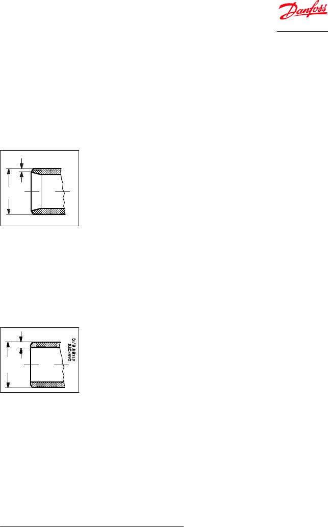
Figure 2: DIN
| <![if ! IE]> <![endif]>Danfoss A148B15.10 |
| <![if ! IE]> <![endif]>T |
| <![if ! IE]> <![endif]>ØD |
Table 2: Butt-weld DIN (EN 10220)
|
Size |
Size |
OD |
T |
OD |
T |
Cone |
|
|
mm |
in. |
mm |
mm |
in. |
in. |
||
|
|
|||||||
REG-SA / SB |
10 |
⅜ |
17.2 |
2.3 |
0.677 |
0.091 |
A and B |
|
REG-SA / SB |
15 |
½ |
21.3 |
2.3 |
0.839 |
0.091 |
A and B |
|
20 |
¾ |
26.9 |
2.3 |
1.059 |
0.091 |
|||
|
|
|||||||
|
25 |
1 |
33.7 |
2.6 |
1.327 |
0.103 |
|
|
REG-SA / SB |
32 |
1¼ |
42.4 |
2.6 |
1.669 |
0.102 |
A and B |
|
|
40 |
1½ |
48.3 |
2.6 |
1.902 |
0.103 |
|
|
REG-SB |
50 |
2 |
60.3 |
2.9 |
2.37 |
0.11 |
B |
|
REG-SB |
65 |
2½ |
76.1 |
2.9 |
3 |
0.11 |
B |
|
|
|
|
|
|
|
|
|
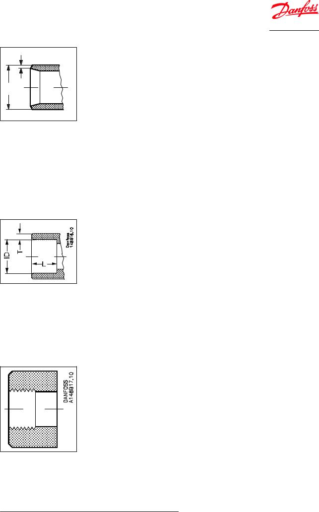
Figure 3: ANSI
| <![if ! IE]> <![endif]>ØD |
<![if ! IE]> <![endif]>T |
Table 3: Butt-weld ANSI (B 36.10 Schedule 80)
|
Size |
Size |
OD |
T |
OD |
T |
Cone |
|
|
mm |
in. |
mm |
mm |
in. |
in. |
||
|
|
|||||||
REG-SA / SB |
10 |
⅜ |
17.2 |
3.2 |
0.677 |
0.126 |
A and B |
|
REG-SA / SB |
15 |
½ |
21.3 |
3.7 |
0.839 |
0.146 |
A and B |
|
20 |
¾ |
26.9 |
4.0 |
1.059 |
0.158 |
|||
|
|
|||||||
|
25 |
1 |
33.7 |
4.6 |
1.327 |
0.181 |
|
|
REG-SA / SB |
32 |
1¼ |
42.4 |
4.9 |
1.669 |
0.193 |
A and B |
|
|
40 |
1½ |
48.3 |
5.1 |
1.902 |
0.201 |
|
|
|
|
|
|
|
|
|
|
Table 4: Butt-weld ANSI (B 36.10 Schedule 40)
|
Size |
Size |
OD |
T |
OD |
T |
Cone |
|
mm |
in. |
mm |
mm |
in. |
in. |
|
|
|
||||||
REG-SB |
50 |
2 |
60.3 |
3.9 |
2.37 |
0.15 |
B |
REG-SB |
65 |
2½ |
73.0 |
5.2 |
2.87 |
0.20 |
B |
|
|
|
|
|
|
|
|
© Danfoss | Climate Solutions | 2021.03 |
AI189386433903en-021201 | 5 |
Hand operated regulating valve, type REG-SA and REG-SB 10-65
Figure 4: GOST
| <![if ! IE]> <![endif]>Danfoss A148B15.10 |
| <![if ! IE]> <![endif]>T |
| <![if ! IE]> <![endif]>ØD |
Table 5: Butt-weld GOST (8734-75 and 8732-78)
|
Size |
Size |
OD |
T |
OD |
T |
Cone |
|
|
mm |
in. |
mm |
mm |
in. |
in. |
||
|
|
|||||||
REG-SA / SB |
10 |
⅜ |
14 |
2 |
0.551 |
0.079 |
A and B |
|
REG-SA / SB |
15 |
½ |
18 |
2 |
0.709 |
0.079 |
A and B |
|
20 |
¾ |
25 |
2.5 |
0.984 |
0.098 |
|||
|
|
|||||||
|
25 |
1 |
32 |
3 |
1.260 |
0.118 |
|
|
REG-SA / SB |
32 |
1¼ |
38 |
3 |
1.496 |
0.118 |
A and B |
|
|
40 |
1½ |
45 |
3 |
1.772 |
0.118 |
|
|
REG-SB |
50 |
2 |
57 |
3.5 |
2.244 |
0.138 |
B |
|
REG-SB |
65 |
2½ |
76.1 |
2.9 |
3 |
0.11 |
B |
|
|
|
|
|
|
|
|
|
Figure 5: SOC
Table 6: Socket welding ANSI (B 16.11)
|
Size |
Size |
OD |
T |
OD |
T |
L |
L |
Cone |
|
|
mm |
in. |
mm |
mm |
in. |
in. |
mm |
in. |
||
|
|
|||||||||
REG-SA / SB |
15 |
½ |
21.8 |
6.0 |
0.858 |
0.235 |
10 |
0.39 |
A and B |
|
20 |
¾ |
27.2 |
7.6 |
1.071 |
0.299 |
13 |
0.51 |
|||
|
|
|||||||||
|
25 |
1 |
33.9 |
7.2 |
1.335 |
0.284 |
13 |
0.51 |
|
|
REG-SA / SB |
32 |
1¼ |
42.7 |
6.1 |
1.743 |
0.240 |
13 |
0.51 |
A and B |
|
|
40 |
1½ |
48.8 |
6.6 |
1.921 |
0.260 |
13 |
0.51 |
|
|
REG-SB |
50 |
2 |
61.2 |
6.2 |
2.41 |
0.24 |
16 |
0.63 |
B |
|
|
|
|
|
|
|
|
|
|
|
Figure 6: FPT
© Danfoss | Climate Solutions | 2021.03 |
AI189386433903en-021201 | 6 |
Hand operated regulating valve, type REG-SA and REG-SB 10-65
Table 7: FPT inside pipe thread, NPT (ANSI/ASME B 1.20.1)
|
Size |
Size |
Inside pipe thread |
Cone |
|
|
mm |
in. |
|||
|
|
|
|||
REG-SA / SB |
15 |
½ |
(½ × 14 NPT) |
A and B |
|
20 |
¾ |
(¾ × 14 NPT) |
|||
|
|
||||
REG-SA / SB |
25 |
1 |
(1 × 11.5 NPT) |
A and B |
|
32 |
1¼ |
(1¼ × 11.5 NPT) |
|||
|
|
||||
|
|
|
|
|
Computation and selection
Introduction
In refrigeration plants, hand operated regulating valves are primarily used in liquid lines in order to regulate the flow of refrigerant. The valves can, however, also be used as expansion valves. From a calculation point of view the two fields of application are very di€erent.
Normal flow is the term used to describe the general case where the flow through the valve is proportional to the square root of the pressure drop across it and inversely proportional to the density of the refrigerant (Bernouillis equation).
This relationship between mass flow, pressure drop and density satisfies the majority of all valve applications with refrigerants and brines.
Normal flow is characterised by turbulent flow through the valve without any phase change. The following capacity curves are based on the above mentioned assumption.
Application of the hand operated regulating valves outside the normal flow area will reduce the capacity of the valve considerably. In such cases it is recommended to use Coolselector®2 (Danfoss calculation and selection software).
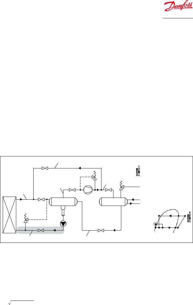
Figure 7: Location of valve in system (marked with grey)
Hot gas by-pass & defrost line |
|
|
Discharge |
Dry suction line |
line |
|
|
Wet suction line |
|
REG |
|
Liquid line without phase change |
Liquid line with or without phase change |
Sizing hand operated regulating valve for liquid flow
Liquid refrigerants: Use the liquid tables, Figure 13: REG-SA 10 and REG-SB 10, Figure 14: REG-SA 15-20 and REG-SB 15-20, Figure 15: REG-SA 25-40 and REG-SB 25-40, Figure 16: REG-SB 50, Figure 17: REG-SB 65. For other refrigerants and brines, "Normal flow" (Turbulent flow); see below and use the flow coeŠcient tables (Figure 8: REG-SA 10 and REG-SB 10, Figure 9: REG-SA 15-20 and REG-SB 15-20, Figure 10: REG-SA 25-40 and REG-SB 25-40, Figure 11: REG-SB 50, Figure 12: REG-SB 65).
SI-units
Mass flow:
kv = |
G |
= G × CA [m3 |
/h] |
|
ρ × 1000 × Δp |
|
|||
|
|
|
|
|
|
|
|||
© Danfoss | Climate Solutions | 2021.03 |
AI189386433903en-021201 | 7 |
|||
Hand operated regulating valve, type REG-SA and REG-SB 10-65
Volume flow: |
|
|
|||||
kv |
= |
|
|
|
|
[m3/h] |
|
1000 × Δp |
|
||||||
|
|
|
|
|
|||
|
|
|
|
ρ |
|
|
|
|
|
|
|
|
|
|
|
|
|
|
k |
v |
[m3/h] |
Quantity [m3/h] of water flowing through a valve at a pressure loss of 1 bar (according to VDE/VDI Norm 2173). |
|
|
|
|
P1 |
[bar] |
Pressure before the valve (upstream). |
||
|
|
|
P2 |
[bar] |
Pressure after the valve (downstream). |
||
|
|
|
Δp |
[bar] |
Actual pressure loss across the valve (P1–P2). |
||
|
|
|
G |
[kg/h] |
Mass flow through the valve. |
||
|
|
|
V |
[m3/h] |
Volume flow through the valve. |
||
|
|
|
ρ |
[kg/m3] |
Density of the refrigerant before the valve. |
||
|
|
|
CA |
|
Calculation factor (See Figure 18: Calculation factor CA). |
||
Imperial units |
|
|
|||||
Mass flow: |
|
|
|||||
C |
= 0.95 × G |
= 31.6 × G × C [USgal/min . ] |
|||||
v |
|
|
ρ × Δp |
|
A |
||
|
|
|
|
|
|||
Volume flow: |
|
|
|||||
C |
= |
0.127 × |
|
[USgal/min . ] |
|
||
|
|
|
|||||
v |
|
|
|
Δp |
|
|
|
|
|
|
|
|
|
||
|
|
|
|
ρ |
|
|
|
|
|
|
|
|
|
|
|
|
|
|
Cv |
[US gal/min] |
Quantity [US gal/min] of water flowing through a valve at a pressure loss of 1 psi. |
||
|
|
|
P1 |
[psi] |
Pressure before the valve (upstream). |
||
|
|
|
P2 |
[psi] |
Pressure after the valve (downstream). |
||
|
|
|
Δp |
[psi] |
Actual pressure loss across the valve (P1–P2). |
||
|
|
|
G |
[lb/min] |
Mass flow through the valve. |
||
|
|
|
V |
[US gal/min] |
Volume flow through the valve. |
||
|
|
|
ρ |
[lb/ft3] |
Density of the refrigerant before the valve. |
||
|
|
|
CA |
|
Calculation factor (See Figure 18: Calculation factor CA). |
||
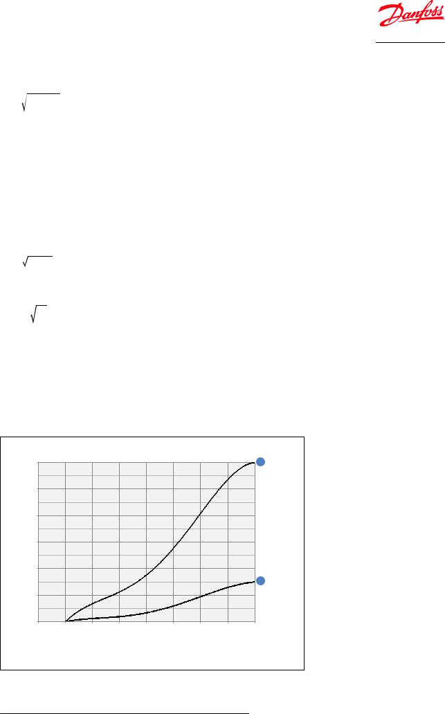
Figure 8: REG-SA 10 and REG-SB 10
Flow coefficient
Kv (Cv) |
|
|
|
|
|
|
|
|
0.6 |
|
|
|
|
|
|
|
B |
(0.70) |
|
|
|
|
|
|
|
|
0.5 |
|
|
|
|
|
|
|
|
(0.58) |
|
|
|
|
|
|
|
|
0.4 |
|
|
|
|
|
|
|
|
(0.46) |
|
|
|
|
|
|
|
|
0.3 |
|
|
|
|
|
|
|
|
(0.35) |
|
|
|
|
|
|
|
|
0.2 |
|
|
|
|
|
|
|
|
(0.23) |
|
|
|
|
|
|
|
A |
|
|
|
|
|
|
|
|
|
0.1 |
|
|
|
|
|
|
|
|
(0.12) |
|
|
|
|
|
|
|
|
0 |
|
|
|
|
|
|
|
|
0 |
1 |
2 |
3 |
4 |
5 |
6 |
7 |
8 |
|
0% |
|
25% |
|
50% |
|
75% |
100% |
Turn of spindle Opening
© Danfoss | Climate Solutions | 2021.03 |
AI189386433903en-021201 | 8 |

Hand operated regulating valve, type REG-SA and REG-SB 10-65
Figure 9: REG-SA 15-20 and REG-SB 15-20
Flow coefficient |
|
|
|
|
|
|
|
|
|
|
Kv (Cv) |
|
|
|
|
|
|
|
|
|
|
5 |
|
|
|
|
|
|
|
|
|
B |
(5.80) |
|
|
|
|
|
|
|
|
|
|
4.5 |
|
|
|
|
|
|
|
|
|
|
(5.22) |
|
|
|
|
|
|
|
|
|
|
4 |
|
|
|
|
|
|
|
|
|
|
(4.64) |
|
|
|
|
|
|
|
|
|
|
3.5 |
|
|
|
|
|
|
|
|
|
|
(4.06) |
|
|
|
|
|
|
|
|
|
|
3 |
|
|
|
|
|
|
|
|
|
|
(3.48) |
|
|
|
|
|
|
|
|
|
|
2.5 |
|
|
|
|
|
|
|
|
|
|
(2.90) |
|
|
|
|
|
|
|
|
|
|
2 |
|
|
|
|
|
|
|
|
|
|
(2.32) |
|
|
|
|
|
|
|
|
|
|
1.5 |
|
|
|
|
|
|
|
|
|
A |
(1.74) |
|
|
|
|
|
|
|
|
|
|
1 |
|
|
|
|
|
|
|
|
|
|
(1.16) |
|
|
|
|
|
|
|
|
|
|
0.5 |
|
|
|
|
|
|
|
|
|
|
(0.58) |
|
|
|
|
|
|
|
|
|
|
0 |
1 |
2 |
3 |
4 |
5 |
6 |
7 |
8 |
9 |
|
0 |
Turn of spindle |
|||||||||
|
0% |
|
25% |
|
50% |
|
|
75% |
100% |
Opening |
Figure 10: REG-SA 25-40 and REG-SB 25-40
Flow coefficient |
|
|
|
|
|
|
|
|
|
|
|
|
|
Kv (Cv) |
|
|
|
|
|
|
|
|
|
|
|
|
|
20 |
|
|
|
|
|
|
|
|
|
|
|
|
B |
(23.20) |
|
|
|
|
|
|
|
|
|
|
|
|
|
18 |
|
|
|
|
|
|
|
|
|
|
|
|
|
(20.88) |
|
|
|
|
|
|
|
|
|
|
|
|
|
16 |
|
|
|
|
|
|
|
|
|
|
|
|
|
(18.56) |
|
|
|
|
|
|
|
|
|
|
|
|
|
14 |
|
|
|
|
|
|
|
|
|
|
|
|
|
(16.24) |
|
|
|
|
|
|
|
|
|
|
|
|
|
12 |
|
|
|
|
|
|
|
|
|
|
|
|
|
(13.92) |
|
|
|
|
|
|
|
|
|
|
|
|
|
10 |
|
|
|
|
|
|
|
|
|
|
|
|
|
(11.60) |
|
|
|
|
|
|
|
|
|
|
|
|
|
8 |
|
|
|
|
|
|
|
|
|
|
|
|
|
(9.28) |
|
|
|
|
|
|
|
|
|
|
|
|
A |
6 |
|
|
|
|
|
|
|
|
|
|
|
|
|
(6.96) |
|
|
|
|
|
|
|
|
|
|
|
|
|
4 |
|
|
|
|
|
|
|
|
|
|
|
|
|
(4.64) |
|
|
|
|
|
|
|
|
|
|
|
|
|
2 |
|
|
|
|
|
|
|
|
|
|
|
|
|
(2.32) |
|
|
|
|
|
|
|
|
|
|
|
|
|
0 |
|
|
|
|
|
|
|
|
|
|
|
|
|
0 |
1 |
2 |
3 |
4 |
5 |
6 |
7 |
8 |
9 |
10 |
11 |
12 |
Turn of spindle |
|
0% |
|
|
25% |
|
|
50% |
|
|
75% |
|
100% |
Opening |
© Danfoss | Climate Solutions | 2021.03 |
AI189386433903en-021201 | 9 |
 Loading...