

Page 1
Working in partnership
Product Sheet
Pre-Fabricated Flushing Bypass Assembly for Terminal Applications
Mini-Flush 40
with
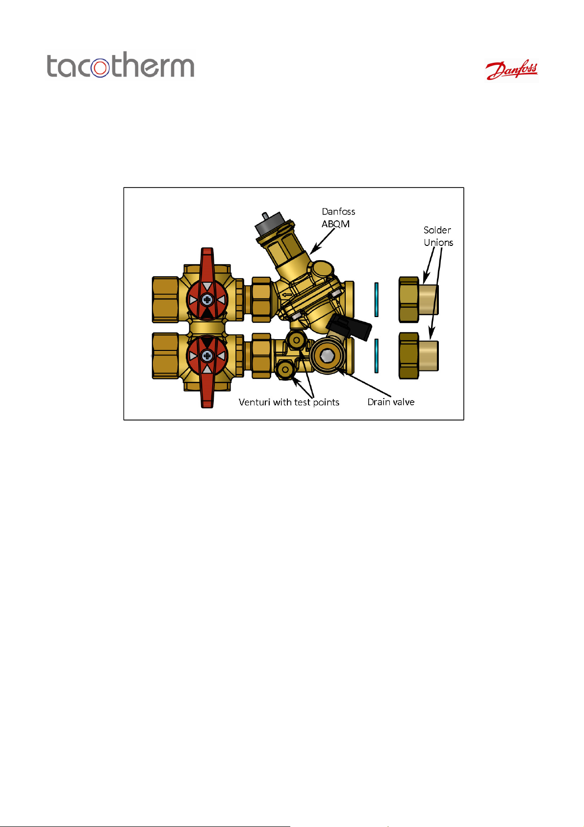
Description
Miniflush 40 is a pre-fabricated, flushing bypass arrangement for balance, control, isolation, and
operation of terminal devices. It is designed for use with fan coil units, chilled beams, and other
terminal devices, where flow is controlled via a pressure independent control valve, and isolation,
drain, flushing bypass, and flow measurement is required.
Key features include:
• A compact, pre-fabricated design
• Factory pressure tested assembly
• Each assembly is labelled with FCU location and Miniflush 40 instructions
• High flow DN15 option for direct connection to CHW terminals with flows up to 0.315 l/s
• Low flow option for LTHW flow rates down to 0.008 l/s
• Left and right handed versions to prevent clashes within the fan coil
• A wide range of connection options, including BSP, compression, and solder connections to the
coil
• Danfoss AB-QM pressure independent control valve for balance at full or partial loads
• A comprehensive compatible range of actuators to enable it to be connected to a building
management system or other controller
• Flow mounted drain for flushing and quick drain-downs
• Flow measurement function in all sizes
Tacotherm Ltd, Unit 40, Hampshire Business Park, Brunel Road, Totton, Ha mpshire, SO40 3SA, UK.
T: 02380 663163 E: sales@tacotherm.co.uk
Tacotherm accept no liability for possible errors in this product sheet. Tacothermr eserve the right to alter this product without notice. This product us supplied by Tacotherm Limited
Page 2
Working in partnership
Connection
with
Product Sheet Pre-Fabricated Terminal Assembly Type: Mini-Flush 40
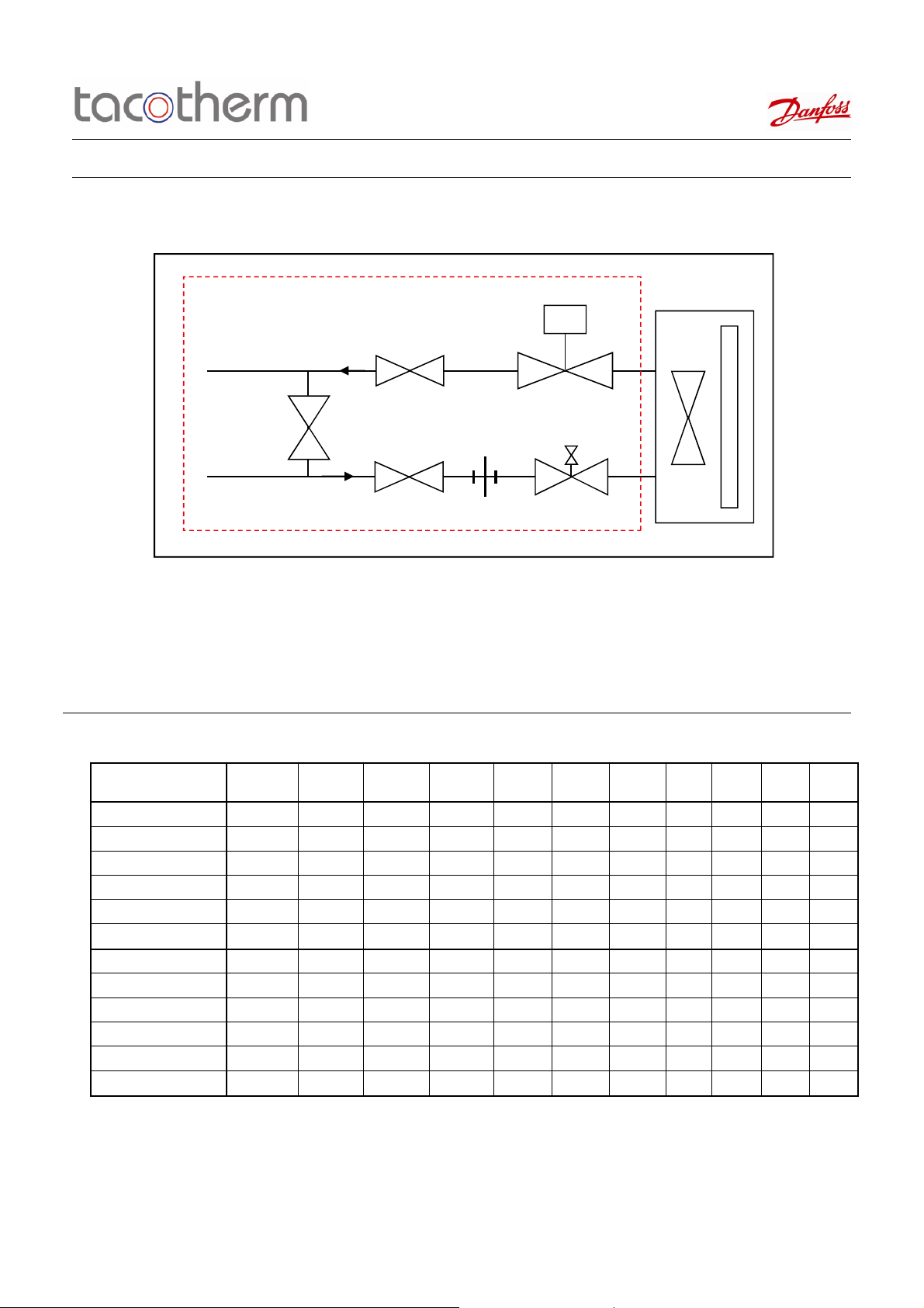
Schematic and Design
AB-QM
IV
IV (NC)
IV
Schematic Symbol Guide
AB-QM -Pressure Independent Control Valve (actuator supplied separately)
DOC -Drain point
IV -Isolation valve
MS -Measuring station
Ordering
Type
Miniflush 40 10LF 0.3 Left Handed 150 60 30 0.3
Miniflush 40 15LF 0.6 Left Handed 275 90 60 0.6
Miniflush 40 15LF 0.9 Left Handed 275 230 90 0.9
Miniflush 40 15 2.1 Left Handed 450 450 230 2.1
Miniflush 40 15HF 4.0 Left Handed 1135 600 450 4.0
Miniflush 40 15HF 5.6 Left Handed 1135 1135 600 5.6
Miniflush 40 10LF 0.3 Right Handed 150 60 30 0.3
Miniflush 40 15LF 0.6 Right Handed 275 90 60 0.6
Miniflush 40 15LF 0.9 Right Handed 275 230 90 0.9
Miniflush 40 15 2.1 Right Handed 450 450 230 2.1
Miniflush 40 15HF 4.0 Right Handed 1135 600 450 4.0
Miniflush 40 15HF 5.6 Right Handed 1135 1135 600 5.6
Position on
Terminal
Nominal Valve
Flow Rate l/h
Recommended
Q Max (l/h)
Recommended
Q Min (l/h)
MS
Orifice kVs
DOC
Connection
Size
3/4" x 15 or
22mm
3/4" x 15 or
22mm
3/4" x 15 or
22mm
3/4" x 15 or
22mm
3/4" x 15 or
22mm
3/4" x 15 or
22mm
3/4" x 15 or
22mm
3/4" x 15 or
22mm
3/4" x 15 or
22mm
3/4" x 15 or
22mm
3/4" x 15 or
22mm
3/4" x 15 or
22mm
Connection
Type
Pipework
Internal
Threaded
Internal
Threaded
Internal
Threaded
Internal
Threaded
Internal
Threaded
Internal
Threaded
Internal
Threaded
Internal
Threaded
Internal
Threaded
Internal
Threaded
Internal
Threaded
Internal
Threaded
Actuator
Type
Terminal
Modulating
Solder AME 110NL AMV 110NL TWA-Z
Solder AME 110NL AMV 110NL TWA-Z
Solder AME 110NL AMV 110NL TWA-Z
Solder AME 110NL AMV 110NL TWA-Z
Solder AME 110NL AMV 110NL TWA-Z
Solder AME 110NL AMV 110NL TWA-Z
Solder AME 110NL AMV 110NL TWA-Z
Solder AME 110NL AMV 110NL TWA-Z
Solder AME 110NL AMV 110NL TWA-Z
Solder AME 110NL AMV 110NL TWA-Z
Solder AME 110NL AMV 110NL TWA-Z
Solder AME 110NL AMV 110NL TWA-Z
Type
Actuator
Type
3-Point
Actuator
Thermic
Type
Notes:
-The recommended flow rates are to enable accurate measurement of flow
-Actuators need to be ordered separately
-Options are available for connection to the pipework and terminal. Please discuss with your representative prior to ordering
Tacotherm Ltd, Unit 40, Hampshire Business Park, Brunel Road, Totton, Ha mpshire, SO40 3SA, UK.
T: 02380 663163 E: sales@tacotherm.co.uk
Tacotherm accept no liability for possible errors in this product sheet. Tacothermr eserve the right to alter this product without notice. This product us supplied by Tacotherm Limited
Page 3
Working in partnership
with
Product Sheet Pre-Fabricated Terminal Assembly Type: Mini-Flush 40
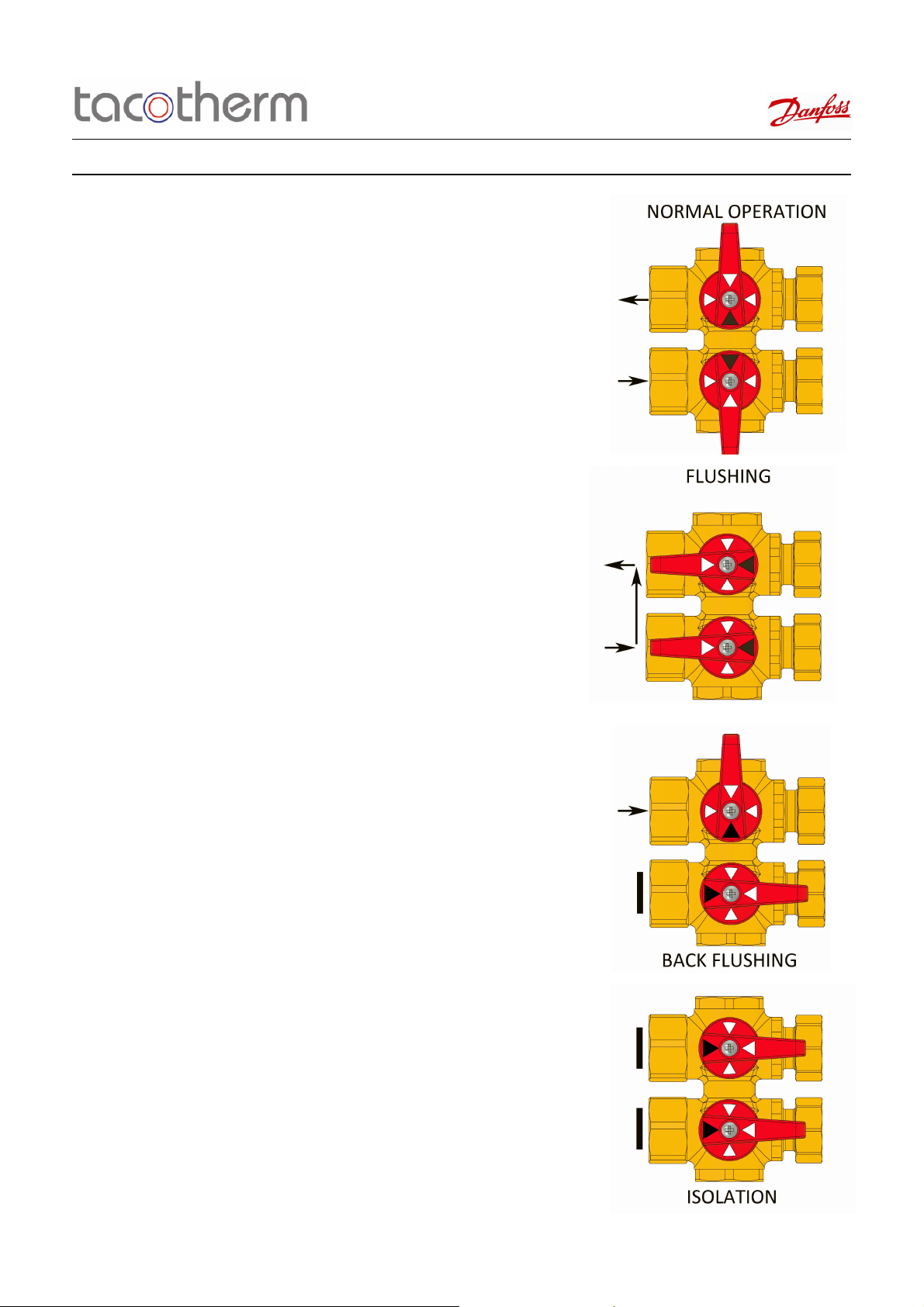
Operational Modes
Normal Operation
This is the supply operation of the Mini-flush,
with flow going through terminal, and out
through the return, back to the system.
The AB-QM valve will balance by limiting the
flow to the coil, and the actuator will control
flow as per the temperature requirement.
Flushing
During system flushing, the terminal will be
isolated, but a flow around the main system is
required. To enable bypassing we have
positioned a flushing bypass within the Miniflush assembly, which can open a link between
flow and return, to enable mainline system
flow for flushing.
Back Flushing
To enable flushing through the terminal, the
return can be opened, with the flow and
bypass isolation valves closed. The drain is
then opened, to allow flow through the coil,
and any coil debris will be released through
the flow side drain point.
Isolation
For a variety of reasons, it may be required to
completely isolate the terminal. For this we
can isolate the flow and return, and close the
bypass, to remove all flow through the coil
and bypass.
Tacotherm Ltd, Unit 40, Hampshire Business Park, Brunel Road, Totton, Ha mpshire, SO40 3SA, UK.
T: 02380 663163 E: sales@tacotherm.co.uk
Tacotherm accept no liability for possible errors in this product sheet. Tacothermr eserve the right to alter this product without notice. This product us supplied by Tacotherm Limited
Page 4
Working in partnership
with
Product Sheet Pre-Fabricated Terminal Assembly Type: Mini-Flush 40
Pressure Independent Control Valve Specification
Description
The precise flow control performance of the AB-QM with a Danfoss actuator provides
increased comfort and superior Total Cost of Ownership because of savings made on:
• Efficient energy transfer and minimal pumping costs since there are no overflows at
partial loads because of the exact pressure independent flow limitation.
• Smaller pump investments and lower energy consumption as the pump head needed
is lower than in the traditional setup. With the built in test plugs it is easy to
troubleshoot and find the optimal setpoint for the pump.
• Reduced movements of the actuator since the built-in differential pressure controller
ensure the pressure fluctuations do not influence the room temperature.
• Achieving a stable temperature in a room leading to a lower average temperature at
the same comfort level.
• Minimal flow complaints, as the valve performs as designed, and has been tested by
BSRIA to demonstrate flow performance.
• Minimal blockage complaints, as the AB-QM diaphragm design has the advantage of
being ‘dirt tolerant’ unlike a cartridge type designed PICV.
• Trouble-free segmentation of the building project. When sections of a project are
finished they can normally not be handed over to the customer with a fully functional
HVAC installation. However the AB-QM with a Danfoss actuator will automatically
control the flow, even when other parts of the installation are still unfinished. It’s not
needed to adjust the AB-QM after finalisation of the project.
• Commissioning costs, the costs are close to zero because of a convenient setting
procedure without the need for flow charts, calculations or measuring equipment.
The AB-QM valves can be set to a precise design value even when the system is up
and running.
• Halved mounting costs as the AB-QM valve covers two functions, Balancing & Control
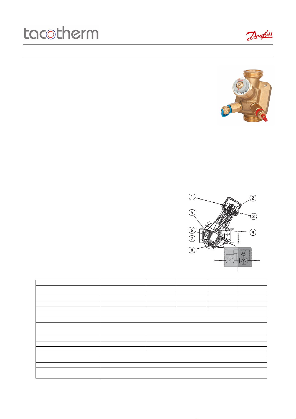
Operation of the AB-QM Balancing and Control Valve
Differential pressure controller DPC
The differential pressure controller maintains a constant differential pressure across the
control valve. The pressure difference ΔpCv (P2-P3) on th e membrane is balanced with
the force of the spring. Whenever the differential pressure across the control
valve changes (due to a change in available pressure, or movement of the control valve)
the hollow cone is displaced to a new position which brings a new equilibrium and
therefore keeps the differential pressure at a constant level.
Control valve Cv
The control valve has a linear characteristic. It features a stroke limitation function that
allows adjustment of the Kv value. The percentage marked on the scale equals the
percentage of 100 % flow marked on the pointer. Changing the stroke limitation is done
by lifting the blocking mechanism and turning the top of the valve to the desired position,
showed on the scale as a percentage. A blocking mechanism automatically prevents
unwanted changing of the setting.
PICV Technical Details
Size 10LF 15LF 15 15HF
Flow Range l/s Nom 0.042 0.076 0.125 0.315
Min 0.008 0.015 0.025 0.063
Standard Setting Range 20-100%
Starting Differential Pressure kPa 16 16 16 35
Max Differential Pressure Bar 6 6 6 6
Control Range 1:1000
Control Characteristic Linear/Logarithmic with actuator
Leakage Rate No visible leakage
Flow Medium
Pressure Rating PN 10 as Standard (16 is available on request)
Medium Temperature º C -10…+120
Storage and Transport Temp º C -40…70
Stroke mm 2.25
PICV Connection Union Threaded/Solder
Body Material DZR Brass
Membrane and O-Ring Material EPDM
Control Valve Cone Material CuZn40Pb3-CW614N
Water and water mixtures for closed heating and cooling systems according to plant type I for DIN EN14868
Tacotherm Ltd, Unit 40, Hampshire Business Park, Brunel Road, Totton, Ha mpshire, SO40 3SA, UK.
T: 02380 663163 E: sales@tacotherm.co.uk
Tacotherm accept no liability for possible errors in this product sheet. Tacothermr eserve the right to alter this product without notice. This product us supplied by Tacotherm Limited
Page 5
Working in partnership
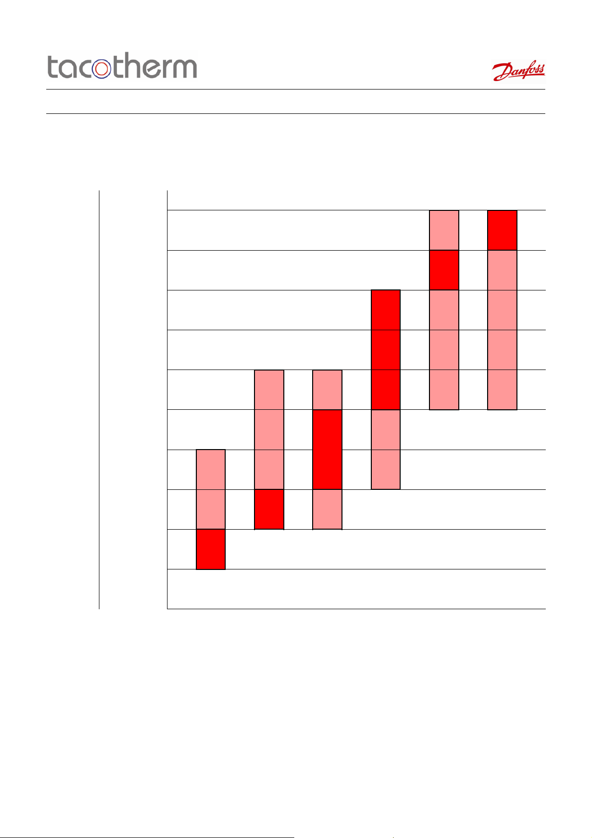
To select a manifold size take your required design flow rate. Find the flow points it falls between on the flow axis, draw
Where you have intersected a manifold in pink, you can select this manifold but it may not be the optimum selection for
with
Product Sheet Pre-Fabricated Terminal Assembly Type: Mini-Flush 40
Selection Chart
Flow Rate l/s Flow Rate l/h
0.32 1135
0.17 600
0.13 450
0.09 340
0.08 275
0.06 230
0.04 150
0.03 90
0.017 60
0.008 30
Orifice kVs: 0.3 0.6 0.9 2.1 4.0 5.6
Mini-Flush 10LF 15LF 15LF 15 15HF 15HF
This chart is for guidance only. Any selections must be checked with a Tacotherm representative before a final selection
Notes:
Tacotherm Ltd, Unit 40, Hampshire Business Park, Brunel Road, Totton, Ha mpshire, SO40 3SA, UK.
T: 02380 663163 E: sales@tacotherm.co.uk
Tacotherm accept no liability for possible errors in this product sheet. Tacothermr eserve the right to alter this product without notice. This product us supplied by Tacotherm Limited
can be made
a line horizontally. Select the manifolds in red for optimum selection
accurate flow measurement and you may experience high orifice pressure loss. PICV flow control performance will not
be affected by selection within this range.
Page 6

Working in partnership
with
Product Sheet Pre-Fabricated Terminal Assembly Type: Mini-Flush 40
Pressure Independent Control Valve
Specification
Setting the AB-QM
The calculated flow can be adjusted easily without using special tools.
To change the presetting (factory setting is 100 %) follow the four
steps below:
① Remove the blue protective cap or the mounted actuator
② Raise the grey pointer
③ Turn (clock wise to decrease) to the new presetting
④ Press grey pointer back into lock position.
After click presetting is locked.
The presetting scale indicates values from 100 % flow to 0 %. Clock
wise turning would decrease the flow value while counter clock wise
would increase it.
If the valve is a DN 15 then the nom flow
= 450 l/h =100 % presetting. To set a flow of 270 l/h you have to set:
270/450 = 60 %.
Tacotherm recommends a presetting/flow from 20 % to 100 %.
Factory presetting is 100 %.
Verification of Flow Rate on Mini-Flush
To verify the flow rate, the following steps should be taken:
① Find the kVs of the measuring station on the orifice kVs chart
② Calculate the required pressure drop using the kVs and design flow rate, using the following formula:
Q=Kv x √∆P
Note Q=m3/h, ∆P=Bar
③ Plug a manometer into the test points on the measuring station
④ If you are getting the required pressure, you have the desired flow rate
A guide to the expected pressure losses can be found in the chart below:
Manifold Type
Miniflush 40 10LF 0.3 150 0.3 25.000 20.250 16.000 12.250 9.000 6.250 4.000 2.250 1.000
Miniflush 40 15LF 0.6 275 0.6 21.007 17.016 13.444 10.293 7.563 5.252 3.361 1.891 0.840
Miniflush 40 15LF 0.9 275 0.9 9.336 7.563 5.975 4.575 3.361 2.334 1.494 0.840 0.373
Miniflush 40 15 2.1 450 2.4 3.516 2.848 2.250 1.723 1.266 0.879 0.563 0.316 0.141
Miniflush 40 15HF 4 1135 4.0 8.051 6.522 5.153 3.945 2.899 2.013 1.288 0.725 0.322
Miniflush 40 15HF 5.6 1135 5.6 4.108 3.327 2.629 2.013 1.479 1.027 0.657 0.370 0.164
Nominal Flow Rate
l/h
Orifice Kvs Measuring Station Pressure Drop at PICV Setting (kPa)
100% 90% 80% 70% 60% 50% 40% 30% 20%
The highlighted cells, indicate the best settings for flow rate measurement
Tacotherm Ltd, Unit 40, Hampshire Business Park, Brunel Road, Totton, Ha mpshire, SO40 3SA, UK.
T: 02380 663163 E: sales@tacotherm.co.uk
Tacotherm accept no liability for possible errors in this product sheet. Tacothermr eserve the right to alter this product without notice. This product us supplied by Tacotherm Limited
Page 7

Working in partnership
with
Product Sheet Pre-Fabricated Terminal Assembly Type: Mini-Flush 40
DN15 Mini-Flush Dimensions
Tacotherm Ltd, Unit 40, Hampshire Business Park, Brunel Road, Totton, Ha mpshire, SO40 3SA, UK.
T: 02380 663163 E: sales@tacotherm.co.uk
Tacotherm accept no liability for possible errors in this product sheet. Tacothermr eserve the right to alter this product without notice. This product us supplied by Tacotherm Limited
 Loading...