

Page 1

Fitters notes Trouble shooting
Page
This chapter is divided into four sections:
Measuring instruments . . . . . . . . . . . . . . . . . . . . . . . . . . . . . . . . . . . . . . . . . . . . . . . . . . . . . . . . . . . . . . . . . . . . . . . . . . 147
Fault location (Danfoss commercial refrigeration controls) . . . . . . . . . . . . . . . . . . . . . . . . . . . . . . . . . . . . . . . . 155
Fault location in refrigeration circuits with hermetic compressors . . . . . . . . . . . . . . . . . . . . . . . . . . . . . . . . . 185
Fault location overview (Danfoss Compressors) . . . . . . . . . . . . . . . . . . . . . . . . . . . . . . . . . . . . . . . . . . . . . . . . . . . 197
© Danfoss A/S (AC-DSL/MWA), 10 - 2006 DKRCC.PF.000.G1.02 / 520H1459 145
Trouble shooting
Page 2

Page 3
Fitters notes Trouble shooting - Measuring instruments
Contents Page
Measuring Instruments . . . . . . . . . . . . . . . . . . . . . . . . . . . . . . . . . . . . . . . . . . . . . . . . . . . . . . . . . . . . . . . . . . . . . . . . . . 149
Instruments for fault location. . . . . . . . . . . . . . . . . . . . . . . . . . . . . . . . . . . . . . . . . . . . . . . . . . . . . . . . . . . . . . . . . 149
Classication of instruments . . . . . . . . . . . . . . . . . . . . . . . . . . . . . . . . . . . . . . . . . . . . . . . . . . . . . . . . . . . . . . . . . . . . . 149
a. Uncertainty. . . . . . . . . . . . . . . . . . . . . . . . . . . . . . . . . . . . . . . . . . . . . . . . . . . . . . . . . . . . . . . . . . . . . . . . . . . . . . . . 149
b. Resolution. . . . . . . . . . . . . . . . . . . . . . . . . . . . . . . . . . . . . . . . . . . . . . . . . . . . . . . . . . . . . . . . . . . . . . . . . . . . . . . . . 149
c. Reproducibility . . . . . . . . . . . . . . . . . . . . . . . . . . . . . . . . . . . . . . . . . . . . . . . . . . . . . . . . . . . . . . . . . . . . . . . . . . . . 150
e. Temperature stability . . . . . . . . . . . . . . . . . . . . . . . . . . . . . . . . . . . . . . . . . . . . . . . . . . . . . . . . . . . . . . . . . . . . . . 150
Electronic instruments . . . . . . . . . . . . . . . . . . . . . . . . . . . . . . . . . . . . . . . . . . . . . . . . . . . . . . . . . . . . . . . . . . . . . . . 150
Check and adjustment . . . . . . . . . . . . . . . . . . . . . . . . . . . . . . . . . . . . . . . . . . . . . . . . . . . . . . . . . . . . . . . . . . . . . . . 150
Adjustment and calibration . . . . . . . . . . . . . . . . . . . . . . . . . . . . . . . . . . . . . . . . . . . . . . . . . . . . . . . . . . . . . . . . . . . . . . 151
Pressure gauges . . . . . . . . . . . . . . . . . . . . . . . . . . . . . . . . . . . . . . . . . . . . . . . . . . . . . . . . . . . . . . . . . . . . . . . . . . . . . 151
Service pressure gauges. . . . . . . . . . . . . . . . . . . . . . . . . . . . . . . . . . . . . . . . . . . . . . . . . . . . . . . . . . . . . . . . . . . . . . 151
Vacuum gauges. . . . . . . . . . . . . . . . . . . . . . . . . . . . . . . . . . . . . . . . . . . . . . . . . . . . . . . . . . . . . . . . . . . . . . . . . . . . . . 151
Thermometer. . . . . . . . . . . . . . . . . . . . . . . . . . . . . . . . . . . . . . . . . . . . . . . . . . . . . . . . . . . . . . . . . . . . . . . . . . . . . . . . 152
Hygrometer . . . . . . . . . . . . . . . . . . . . . . . . . . . . . . . . . . . . . . . . . . . . . . . . . . . . . . . . . . . . . . . . . . . . . . . . . . . . . . . . . 152
© Danfoss A/S (AC-DSL/MWA), 10 - 2006 DKRCC.PF.000.G1.02 / 520H1459 147
Trouble shooting
Page 4

Notes
148 DKRCC.PF.000.G1.02 / 520H1459 © Danfoss A/S (AC-DSL/MWA), 10 - 2006
Page 5
Fitters notes Trouble shooting - Measuring instruments
CLASS N 1
90
Measuring Instruments
Instruments for fault location
Classication of instruments
The items of equipment most often used for
locating faults in refrigeration systems are as
follows:
1. Pressure gauge
2. Thermometer
3. Hygrometer
4. Leak detector
5. Vacuum gauge
6. Clamp ammeter
7. Megger
8. Pole nder
Ae0_0045
Instruments for fault location and servicing
on refrigeration systems should full certain
reliability requirements.
Some of these requirements can be categorised
thus:
a. Uncertainty
b. Resolution
c. Reproducibility
d. Long-term stability
e. Temperature stability
The most important of these are a, b, and e.
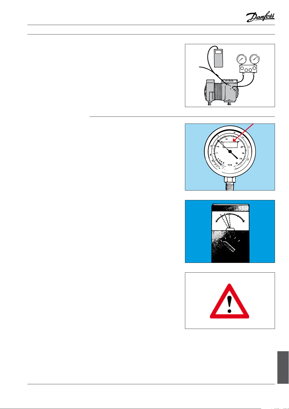
a. Uncertainty
b. Resolution
Ae0_0046
The uncertainty (accuracy) of an instrument is the
accuracy with which it is able to give the value of
the measured variable.
Uncertainty is often expressed in % (±) of
either: Full scale (FS) or the measuring value.
An example of uncertainty for a particular
instrument is ±2% of measuring value, i.e. less
uncertain (more accurate) than if the uncertainty
is ±2% of FS.
Ae0_0047
The resolution of an instrument is the smallest
unit of measurement that can be read from it.
For example, a digital thermometer that shows
0.1°C as the last digit in the reading has a
resolution of 0.1°C.
Resolution is not an expression of accuracy. Even
with a resolution of 0.1°C, an accuracy as poor as
2 K is not uncommon.
It is therefore very important to distinguish
between the two.
Ah0_0006
© Danfoss A/S (AC-DSL/MWA), 10 - 2006 DKRCC.PF.000.G1.02 / 520H1459 149
Trouble shooting
Page 6
Fitters notes Trouble shooting - Measuring instruments
c. Reproducibility
e. Temperature stability
The reproducibility of an instrument is its ability
to repeatedly show the same result for a constant
measuring value.
Reproducibility is given in % (±).
d. Long-term stability
Long-term stability is an expression how much
the absolute accuracy of the instrument changes
in, say, one year.
Long-term stability is given in % per year.
Ae0_0003
The temperature stability of an instrument is how
much its absolute accuracy changes for each °C
temperature change the instrument is exposed
to.
Temperature stability is given in % per °C.
Knowledge of the temperature stability of the
instrument is of course important if it is taken
into a cold room or deep freeze store.
Ae0_0004
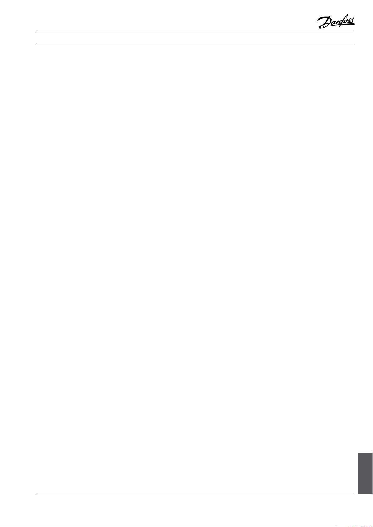
Electronic instruments
Check and adjustment
Electronic instruments can be sensitive to humidity.
Some can be damaged by condensate if operated immediately after they have been moved
from cold to warmer surroundings.
They must not be operated until the whole
instrument has been given time to assume the
ambient temperature.
Never use electronic equipment immediately
after it has been taken from a cold service vehicle
into warmer surroundings.
Ae0_0005
Readings from ordinary instruments, and perhaps
some of their characteristics, change with time.
Nearly all instruments should therefore be
checked at regular intervals and adjusted if
necessary.
Simple checks that can be made are described
below, although they cannot replace the kind of
inspection mentioned above.
Ae0_0006
150 DKRCC.PF.000.G1.02 / 520H1459 © Danfoss A/S (AC-DSL/MWA), 10 - 2006
Page 7
Fitters notes Trouble shooting - Measuring instruments
Check and adjustment (cont.)
Adjustment and calibration
Pressure gauges
The proper nal inspection and adjustment of
instruments can be performed by approved test
institutions.
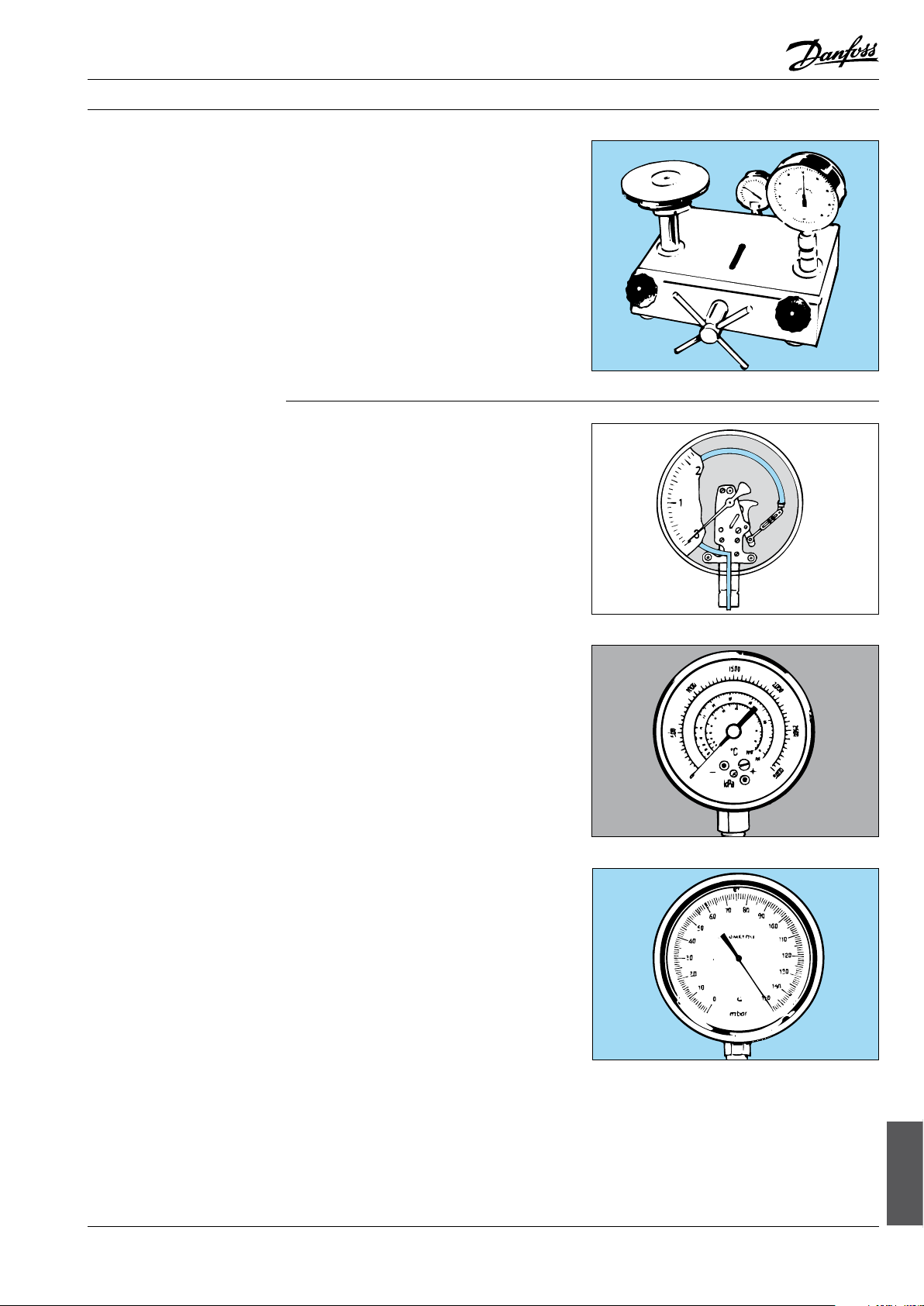
Pressure gauges for fault location and servicing
are as a rule of the Bourdon tube type. Pressure
gauges in systems are also usually of this type.
In practice, pressure is nearly always measured as
overpressure.
The zero point for the pressure scale is equal to
the normal barometer reading.
Therefore pressure gauges have a scale from
–1 bar (–100 kPa) greater than 0 to + maximum
reading. Pressure gauges with a scale in absolute
pressure show about 1 bar in atmospheric
pressure.
Ae0_0007
Ae0_0008
Service pressure gauges
Vacuum gauges
As a rule, service pressure gauges have one
or more temperature scales for the saturation
temperature of common refrigerants.
Pressure gauges should have an accessible
setting screw for zero point adjustment, i.e. a
Bourdon tube becomes set if the instrument has
been exposed to high pressure for some time.
Pressure gauges should be regularly checked
against an accurate instrument. A daily check
should be made to ensure that the pressure
gauge shows 0 bar at atmospheric pressure.
Ae0_0009
Vacuum gauges are used in refrigeration to
measure the pressure in the pipework during and
after an evacuation process.
Vacuum gauges always show absolute pres-sure
(zero point corresponding to absolute vacuum).
Vacuum gauges should not normally be exposed
to marked overpressure and should therefore be
installed together with a safety valve set for the
maximum permissible pressure of the vacuum
gauge.
Ae0_0010
© Danfoss A/S (AC-DSL/MWA), 10 - 2006 DKRCC.PF.000.G1.02 / 520H1459 151
Trouble shooting
Page 8
Fitters notes Trouble shooting - Measuring instruments
Thermometer
Hygrometer
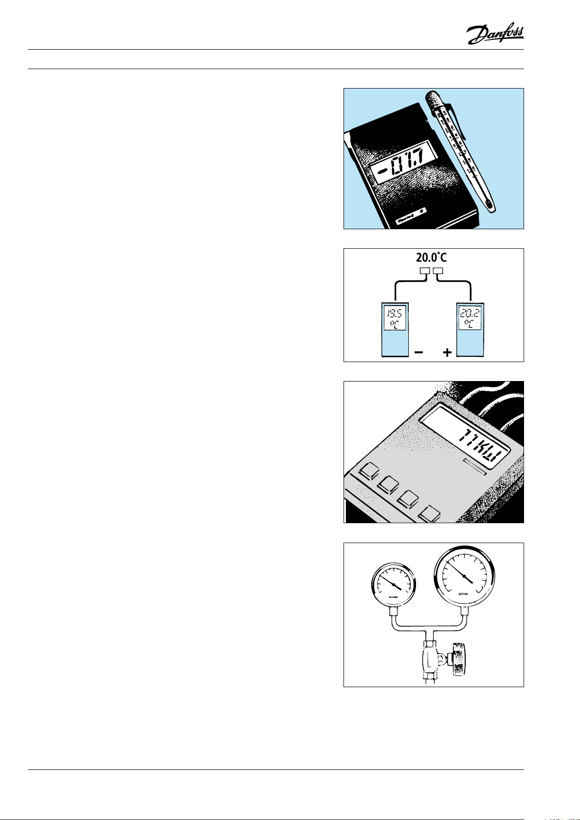
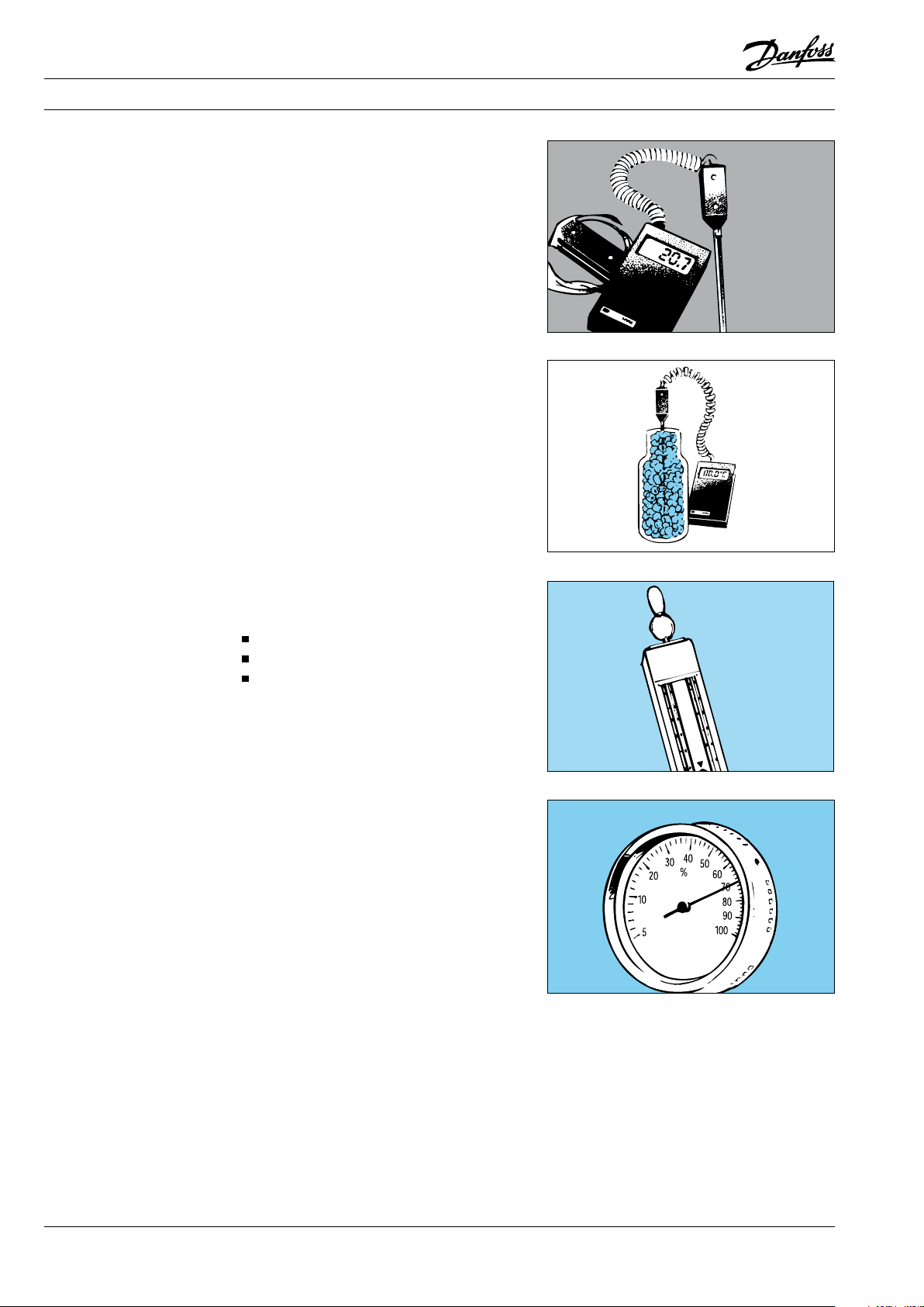
Electronic thermometers with digital read-out
are in widespread use for servicing. Examples of
sensor versions are surface sensors, room sensors
and insertion sensors.
Thermometer uncertainty should not be greater
than 0.1 K and the resolution should be 0.1°C.
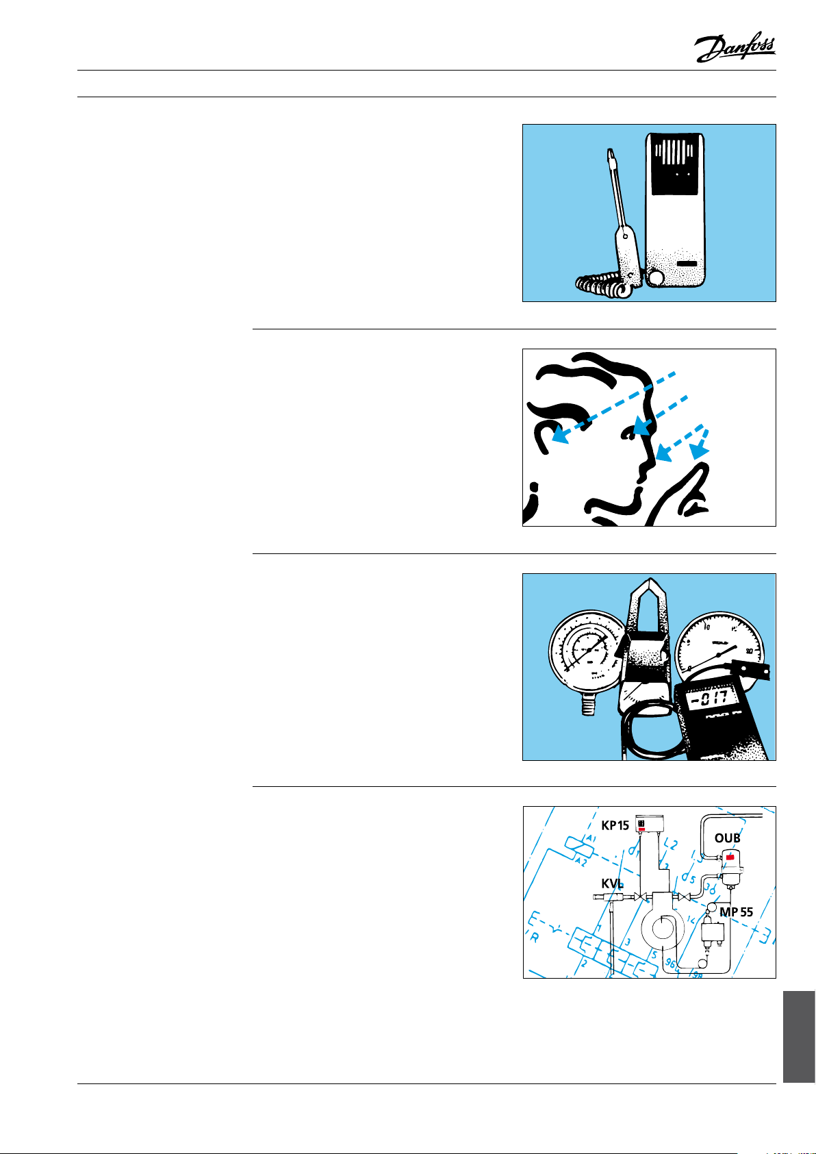
A pointer thermometer with vapour charged
bulb and capillary tube is often recommended for
setting thermostatic expansion valves.
As a rule it is easier to follow temperature variations with this type of thermometer.
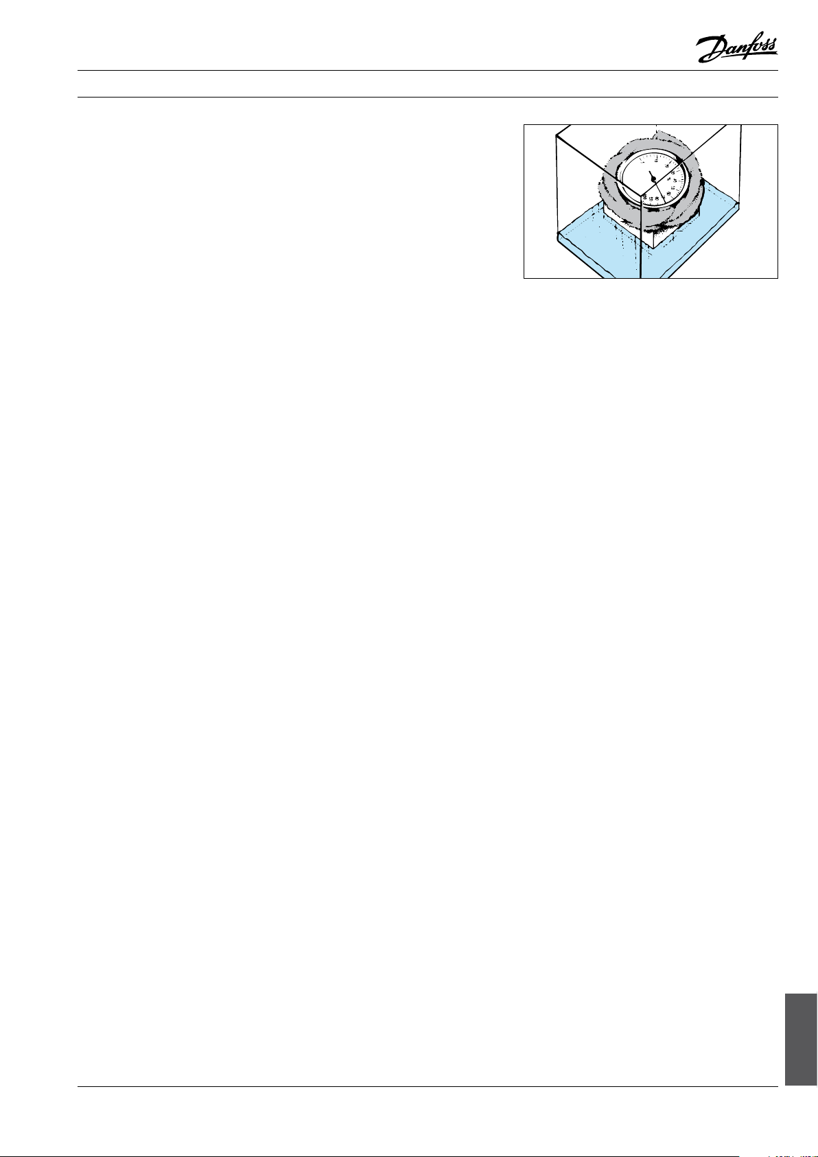
Thermometers can be relatively easily checked
at 0°C in that the bulb can be inserted 150 to 200
mm down into a thermos bottle containing a
mixture of crushed ice (from distilled water) and
distilled water. The crushed ice must ll the whole
bottle.
If the bulb will withstand boiling water, it can
be held in the surface of boilover water from
a container with lid. These are two reasonable
checks for 0°C and 100°C.
A proper check can be performed by a recognised test institute.
There are dierent types of hygrometers for
measuring the humidity in cold rooms and air
conditioned rooms or ducts:
Hair hygrometer
Psychrometer
Diverse electronic hygrometers
A hair hygrometer needs adjustment each time it
is used if reasonable accuracy is to be maintained.
A psychrometer (wet and dry thermometer) does
not require adjustment if its thermometers are of
high quality.
At low temperature and high humidity, the
temperature dierential between wet and dry
thermometers will be small.
Therefore, with psychrometers the uncertainty is
high under such conditions and an adjusted hair
hygrometer or one of the electronic hygrometers
will be more suitable.
Ae0_0011
Ae0_0013
Ae0_0014
Ae0_0015
152 DKRCC.PF.000.G1.02 / 520H1459 © Danfoss A/S (AC-DSL/MWA), 10 - 2006
Page 9
Fitters notes Trouble shooting - Measuring instruments
Hygrometer (continued)
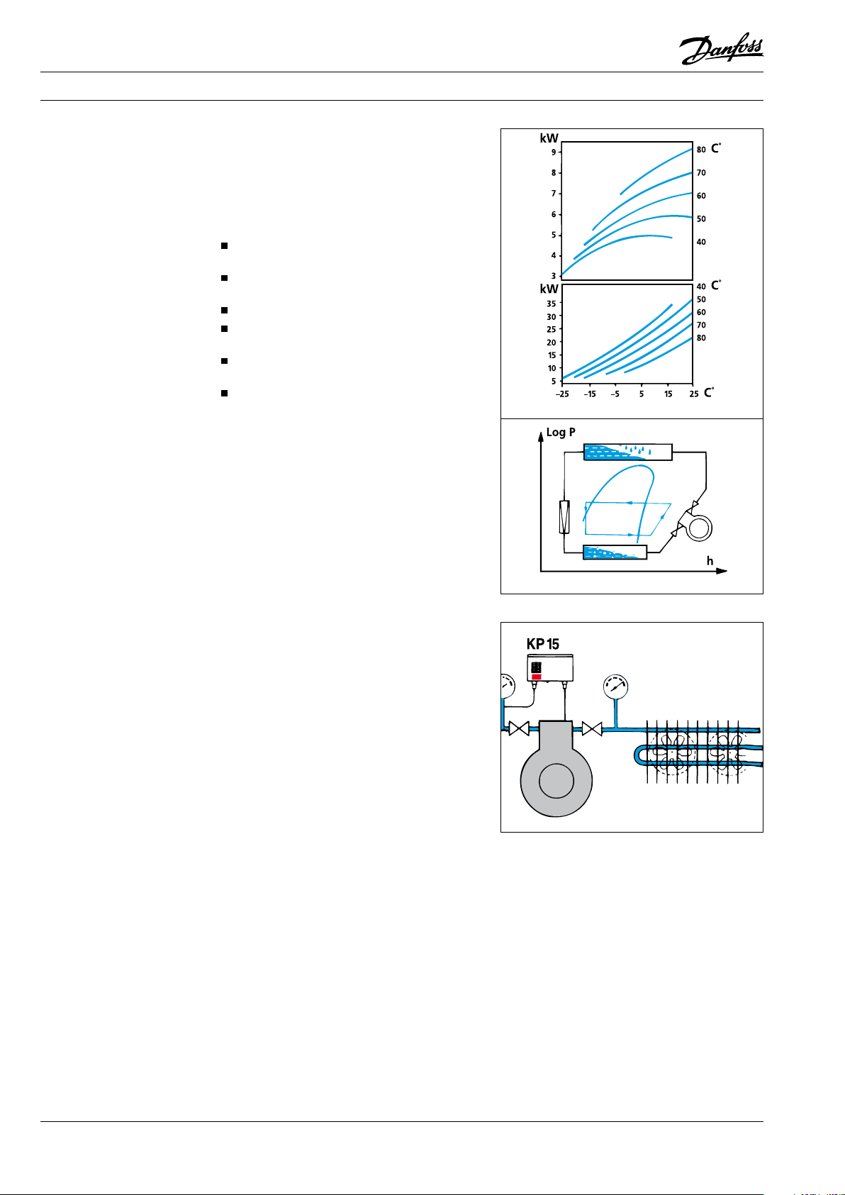
A hair hygrometer can be adjusted by winding
a clean, damp cloth around it and then placing
it in an airtight container with water at the
bottom (no water must be allowed to enter the
hygrometer or come into contact with its bulb).
The container with hygrometer is then allowed
to stand for at least two hours in the same
temperature as that at which measurements are
to be taken.
The hygrometer must now show 100%. If it does
not, the setting screw can be adjusted.
Ae0_0049
© Danfoss A/S (AC-DSL/MWA), 10 - 2006 DKRCC.PF.000.G1.02 / 520H1459 153
Trouble shooting
Page 10

Page 11

Fitters notes Trouble shooting - Fault location (Danfoss commercial refrigeration controls)
Contents Page
Faults on refrigeration systems, general . . . . . . . . . . . . . . . . . . . . . . . . . . . . . . . . . . . . . . . . . . . . . . . . . . . . . . . . . . 157
Fault location without . . . . . . . . . . . . . . . . . . . . . . . . . . . . . . . . . . . . . . . . . . . . . . . . . . . . . . . . . . . . . . . . . . . . . . . 157
the use of instruments . . . . . . . . . . . . . . . . . . . . . . . . . . . . . . . . . . . . . . . . . . . . . . . . . . . . . . . . . . . . . . . . . . . . . . . 157
Categorisation . . . . . . . . . . . . . . . . . . . . . . . . . . . . . . . . . . . . . . . . . . . . . . . . . . . . . . . . . . . . . . . . . . . . . . . . . . . . . . . 157
Knowledge of the system is required . . . . . . . . . . . . . . . . . . . . . . . . . . . . . . . . . . . . . . . . . . . . . . . . . . . . . . . . . 157
Theoretical knowledge is necessary . . . . . . . . . . . . . . . . . . . . . . . . . . . . . . . . . . . . . . . . . . . . . . . . . . . . . . . . . . 158
Visible faults and the eect on the system operation. . . . . . . . . . . . . . . . . . . . . . . . . . . . . . . . . . . . . . . . . . . . . . 159
Visible faults. . . . . . . . . . . . . . . . . . . . . . . . . . . . . . . . . . . . . . . . . . . . . . . . . . . . . . . . . . . . . . . . . . . . . . . . . . . . . . . . . . . . . 159
Air-cooled condenser . . . . . . . . . . . . . . . . . . . . . . . . . . . . . . . . . . . . . . . . . . . . . . . . . . . . . . . . . . . . . . . . . . . . . . . . 159
Water-cooled condenser . . . . . . . . . . . . . . . . . . . . . . . . . . . . . . . . . . . . . . . . . . . . . . . . . . . . . . . . . . . . . . . . . . . . . 159
Receiver with sight glass . . . . . . . . . . . . . . . . . . . . . . . . . . . . . . . . . . . . . . . . . . . . . . . . . . . . . . . . . . . . . . . . . . . . . 159
Receiver stop valve . . . . . . . . . . . . . . . . . . . . . . . . . . . . . . . . . . . . . . . . . . . . . . . . . . . . . . . . . . . . . . . . . . . . . . . . . . 159
Liquid line . . . . . . . . . . . . . . . . . . . . . . . . . . . . . . . . . . . . . . . . . . . . . . . . . . . . . . . . . . . . . . . . . . . . . . . . . . . . . . . . . . . 159
Filter drier . . . . . . . . . . . . . . . . . . . . . . . . . . . . . . . . . . . . . . . . . . . . . . . . . . . . . . . . . . . . . . . . . . . . . . . . . . . . . . . . . . . 159
Sight glass. . . . . . . . . . . . . . . . . . . . . . . . . . . . . . . . . . . . . . . . . . . . . . . . . . . . . . . . . . . . . . . . . . . . . . . . . . . . . . . . . . . 159
Thermostatic expansion valve . . . . . . . . . . . . . . . . . . . . . . . . . . . . . . . . . . . . . . . . . . . . . . . . . . . . . . . . . . . . . . . . 160
Air cooler . . . . . . . . . . . . . . . . . . . . . . . . . . . . . . . . . . . . . . . . . . . . . . . . . . . . . . . . . . . . . . . . . . . . . . . . . . . . . . . . . . . . 160
Liquid cooler . . . . . . . . . . . . . . . . . . . . . . . . . . . . . . . . . . . . . . . . . . . . . . . . . . . . . . . . . . . . . . . . . . . . . . . . . . . . . . . . 160
Suction line. . . . . . . . . . . . . . . . . . . . . . . . . . . . . . . . . . . . . . . . . . . . . . . . . . . . . . . . . . . . . . . . . . . . . . . . . . . . . . . . . . 161
Regulators in suction line . . . . . . . . . . . . . . . . . . . . . . . . . . . . . . . . . . . . . . . . . . . . . . . . . . . . . . . . . . . . . . . . . . . . 161
Compressor . . . . . . . . . . . . . . . . . . . . . . . . . . . . . . . . . . . . . . . . . . . . . . . . . . . . . . . . . . . . . . . . . . . . . . . . . . . . . . . . . 161
Cold Room . . . . . . . . . . . . . . . . . . . . . . . . . . . . . . . . . . . . . . . . . . . . . . . . . . . . . . . . . . . . . . . . . . . . . . . . . . . . . . . . . . 161
General. . . . . . . . . . . . . . . . . . . . . . . . . . . . . . . . . . . . . . . . . . . . . . . . . . . . . . . . . . . . . . . . . . . . . . . . . . . . . . . . . . . . . . 161
Faults that can be felt, heard or smelled and the eect on the system operation . . . . . . . . . . . . . . . . . . . 162
Faults that can be felt. . . . . . . . . . . . . . . . . . . . . . . . . . . . . . . . . . . . . . . . . . . . . . . . . . . . . . . . . . . . . . . . . . . . . . . . . . . . 162
Solenoid valve . . . . . . . . . . . . . . . . . . . . . . . . . . . . . . . . . . . . . . . . . . . . . . . . . . . . . . . . . . . . . . . . . . . . . . . . . . . . . . . 162
Filter drier . . . . . . . . . . . . . . . . . . . . . . . . . . . . . . . . . . . . . . . . . . . . . . . . . . . . . . . . . . . . . . . . . . . . . . . . . . . . . . . . . . . 162
Faults that can be heard . . . . . . . . . . . . . . . . . . . . . . . . . . . . . . . . . . . . . . . . . . . . . . . . . . . . . . . . . . . . . . . . . . . . . . . . . 162
Regulators in suction line . . . . . . . . . . . . . . . . . . . . . . . . . . . . . . . . . . . . . . . . . . . . . . . . . . . . . . . . . . . . . . . . . . . . 162
Compressor . . . . . . . . . . . . . . . . . . . . . . . . . . . . . . . . . . . . . . . . . . . . . . . . . . . . . . . . . . . . . . . . . . . . . . . . . . . . . . . . . 162
Cold room . . . . . . . . . . . . . . . . . . . . . . . . . . . . . . . . . . . . . . . . . . . . . . . . . . . . . . . . . . . . . . . . . . . . . . . . . . . . . . . . . . . 162
Faults that can be smelled . . . . . . . . . . . . . . . . . . . . . . . . . . . . . . . . . . . . . . . . . . . . . . . . . . . . . . . . . . . . . . . . . . . . . . . 162
Cold room . . . . . . . . . . . . . . . . . . . . . . . . . . . . . . . . . . . . . . . . . . . . . . . . . . . . . . . . . . . . . . . . . . . . . . . . . . . . . . . . . . . 162
Refrigeration system with air cooler and air-cooled condenser . . . . . . . . . . . . . . . . . . . . . . . . . . . . . . . . . . . . 163
Refrigeration system with two air coolers and air-cooled condenser . . . . . . . . . . . . . . . . . . . . . . . . . . . . . . . 164
Refrigeration system with liquid cooler and water-cooled condenser. . . . . . . . . . . . . . . . . . . . . . . . . . . . . . 165
Guide to fault location . . . . . . . . . . . . . . . . . . . . . . . . . . . . . . . . . . . . . . . . . . . . . . . . . . . . . . . . . . . . . . . . . . . . . . . . . . . 166
System fault location . . . . . . . . . . . . . . . . . . . . . . . . . . . . . . . . . . . . . . . . . . . . . . . . . . . . . . . . . . . . . . . . . . . . . . . . . . . . 167
Fault location on the thermostatic expansion valve . . . . . . . . . . . . . . . . . . . . . . . . . . . . . . . . . . . . . . . . . . . . . . . 175
Fault location on the solenoid valve . . . . . . . . . . . . . . . . . . . . . . . . . . . . . . . . . . . . . . . . . . . . . . . . . . . . . . . . . . . . . . 177
Fault location on the pressure control . . . . . . . . . . . . . . . . . . . . . . . . . . . . . . . . . . . . . . . . . . . . . . . . . . . . . . . . . . . . 179
Fault location on the thermostat . . . . . . . . . . . . . . . . . . . . . . . . . . . . . . . . . . . . . . . . . . . . . . . . . . . . . . . . . . . . . . . . . 180
Fault location on the water valve . . . . . . . . . . . . . . . . . . . . . . . . . . . . . . . . . . . . . . . . . . . . . . . . . . . . . . . . . . . . . . . . . 181
Fault location on the lter or sight glass . . . . . . . . . . . . . . . . . . . . . . . . . . . . . . . . . . . . . . . . . . . . . . . . . . . . . . . . . . 182
Fault location on the KV pressure regulator . . . . . . . . . . . . . . . . . . . . . . . . . . . . . . . . . . . . . . . . . . . . . . . . . . . . . . 183
Trouble shooting
© Danfoss A/S (AC-DSL/MWA), 10 - 2006 DKRCC.PF.000.G1.02 / 520H1459 155
Page 12

Notes
156 DKRCC.PF.000.G1.02 / 520H1459 © Danfoss A/S (AC-DSL/MWA), 10 - 2006
Page 13
Fitters notes Trouble shooting - Fault location (Danfoss commercial refrigeration controls)
Faults on refrigeration
systems, general
Fault location without
the use of instruments
This booklet deals with common faults in small,
relatively simple refrigeration systems.
The faults, fault causes, remedies and eects on
system operation mentioned also apply to more
complicated and large systems.
However, other faults can occur in such systems.
These and faults in electronic regulators are not
dealt with here.
Ae0_0001
After gaining a little experience, many common
faults in a refrigeration system can be localised
visually, by hearing, by feel, and sometimes
by smell. Other faults can only be detected by
instruments.
Categorisation
Knowledge of the system is
required
Ae0_0012
This booklet is divided into two sections. The
rst section deals exclusively with faults that
can be observed directly with the senses. Here,
symptoms, possible causes and the eect on
operation are given.
The second section deals with faults that can
be observed directly with the senses, and those
that can only be detected by instruments.
Here, symptoms and possible causes are given,
together with instructions on remedial action.
Ae0_0028
An important element in the fault location
procedure is familiarity with how the system
is built up, its function and control, both
mechanical and electrical.
Unfamiliarity with the system ought to be
remedied by carefully looking at piping layouts
and other key diagrams and by getting to know
the form of the system (piping, component
placing, and any connected systems, e.g. cooling
towers and brine systems).
Ae0_0029
© Danfoss A/S (AC-DSL/MWA), 10 - 2006 DKRCC.PF.000.G1.02 / 520H1459 157
Trouble shooting
Page 14
Fitters notes Trouble shooting - Fault location (Danfoss commercial refrigeration controls)
Theoretical knowledge is
necessary
A certain amount of theoretical knowledge is
required if faults and incorrect operation are to
be discovered and corrected.
The location of all forms of faults on even
relatively simple refrigeration systems is
conditional on a thorough knowledge of such
factors as:
The build-up of all components, their mode of
operation and characteristics.
Necessary measuring equipment and
measuring techniques.
All refrigeration processes in the system.
The inuence of the surroundings on system
operation.
The function and setting of controls and safety
equipment.
Legislation on the safety of refrigeration
systems and their inspection.
Before examining faults in refrigeration systems,
it could be advantageous to look briey at
the most important instruments used in fault
location.
Ae0_0033
In the following description of faults in refrigeration systems, sections 1 and 2 take as their
starting points the piping diagrams, g. 1, 2 and
3.
The systems are dealt with in the direction
followed by the circuit. Fault symptoms that
can occur are described in circuit order. The
description starts after the compressor discharge
side and proceeds in the direction of the arrows.
Ae0_0034
Ae0_0016
158 DKRCC.PF.000.G1.02 / 520H1459 © Danfoss A/S (AC-DSL/MWA), 10 - 2006
Page 15
Fitters notes Trouble shooting - Fault location (Danfoss commercial refrigeration controls)
Visible faults and the eect on the system operation Text in [ ] indicates fault cause
Visible faults Eect on system operation
Air-cooled condenser
a) Dirt, e.g. grease or dust, sawdust, dried leaves. Faults under a), b), c), d), e) create:
[Lack of maintenance]
b) Fan stopped.
[Motor defect]
[Motor protector cut-out]
c) Fan rotates in wrong direction.
[Installation error]
d) Fan blades damaged.
e) Fins deformed
[Rough treatment]
Water-cooled condenser
with sight glass: See “Receiver”.
Receiver with sight glass
Liquid level too low.
[Insucient refrigerant in system] Vapour/vapour bubbles in liquid line.
[Overcharged evaporator] Low suction pressure or compressor cycling.
[Overcharged condenser during cold period] Low suction pressure or compressor cycling.
Liquid level too high.
[Overcharged system] Excessive condensing pressure possible.
Receiver stop valve
a) Valve closed. System stopped via low-pressure control.
b) Valve partly closed. Vapour bubbles in liquid line.
Liquid line
a) Too small Faults under a), b) and c) cause:
[Sizing error]
b) Too long
[Sizing error]
c) Sharp bends and/or deformed
[Installation error]
Filter drier
Dew or frost formation on surface. Vapour in liquid line.
[Filter partly blocked with dirt on inlet side]
Sight glass Risk of:
a) Yellow Acid formation, corrosion, motor burn-out, water freezing in
[Moisture in system]
b) Brown Risk of wear in moving parts and blockage in valves and lters.
[Dirt particles in system]
c) Pure vapour in sight glass. Standstill via low-pressure control or compressor cycling.
[Insucient liquid in system]
[Valve in liquid line closed] Standstill via low-pressure control.
[Complete blockage, e.g. of lter drier] Standstill via low-pressure control.
d) Liquid and vapour bubbles in sight glass. All faults under d):
[Insucient liquid in system]
[Valve in liquid line partly closed]
[Partial blockage, e.g. of lter drier]
[No subcooling]
- Increased condensing pressure.
- Reduced refrigeration output.
- Increased energy consumption.
For an air-cooled condenser, the dierence between air inlet
and condensing temperatures should lie between 10 K and 20 K,
preferably at the lower end.
For a water-cooled condenser, the dierence between condensing
and water inlet temperatures should lie between 10 K and 20 K,
preferably at the lower end.
Low suction pressure or compressor cycling.
Large pressure drop in liquid line.
Vapour in liquid line.
thermostatic expansion valve.
Compressor cycling or running at low suction pressure.
Trouble shooting
© Danfoss A/S (AC-DSL/MWA), 10 - 2006 DKRCC.PF.000.G1.02 / 520H1459 159
Page 16
Fitters notes Trouble shooting - Fault location (Danfoss commercial refrigeration controls)
Visible faults and the eect on the system operation (cont.) Text in [ ] indicates fault cause
Visible faults Eect on system operation
Thermostatic expansion valve
a) Thermostatic expansion valve heavily frosted, frost on
evaporator only near valve.
[Dirt strainer partly blocked]
[Bulb charge partly lost]
[Previously described faults causing vapour bubbles in
liquid line]
b) Thermostatic expansion valve without external pressure
equalisation, evaporator with liquid distributor.
[Sizing or installation error]
c) Thermostatic expansion valve with external pressure
equalisation, equalising tube not mounted.
[Installation error]
d) Bulb not rmly secured. Faults under d), e), f) lead to overcharged evaporator with risk of
[Installation error]
e) Entire bulb length not in contact with tube.
[Installation error]
f) Bulb placed in air current.
[Installation error]
Air cooler
a) Evaporator frosted only on inlet side, thermostatic expansion
valve heavily frosted.
[Thermal valve fault]
[All previously described faults that cause vapour in
liquid line]
b) Front blocked with frost. Faults under a), b), c), d), e) cause:
[Lacking, incorrect or wrongly set up defrost procedure]
c) Fan does not run.
[Motor defect or motor protector cut-out]
d) Fan blades defective.
e) Fins deformed.
[Rough treatment]
Liquid cooler
a) Thermostatic expansion valve bulb not rmly secured. Causes overcharged evaporator with risk of liquid ow to
[Installation error]
b) Thermostatic expansion valve without external pressure
equalising on liquid cooler with high pressure drop, e.g.
coaxial evaporator.
[Sizing or installation error]
c) Thermostatic expansion valve with external pressure
equalisation, equalising tube not mounted.
[Installation error]
Faults under a) cause operation at low suction pressure or
compressor cycling via low-pressure control.
Faults under b), c) cause operation at low suction pressure or
compressor cycling via low-pressure control. or compressor
cycling via low-pressure control.
liquid ow to compressor and compressor damage.
Faults under a) cause:
High superheat at evaporator outlet and operation at mostly low
suction pressure.
- Operation with mostly low suction pressure.
- Reduced refrigeration output.
- Increased energy consumption.
For thermostatic expansion valve controlled evaporators:
The dierence between air inlet and evaporating temperatures
should lie between 6 K and 15 K, preferably at the lower end.
For level-controlled evaporators:
The dierence between air inlet and evaporating temperatures
should lie between 2 K and 8 K, preferably at the lower end.
compressor and compressor damage.
Faults b), c) cause:
- Operation with mostly low suction pressure.
- Reduced refrigeration output.
- Increased energy consumption.
For thermostatic expansion valve controlled evaporators:
The dierence between air inlet and evaporating temperatures
should lie between 6 K and 15 K, preferably at the lower end.
For level-controlled evaporators:
The dierence between air inlet and evaporating temperatures
should lie between 2 K and 8 K, preferably at the lower end.
160 DKRCC.PF.000.G1.02 / 520H1459 © Danfoss A/S (AC-DSL/MWA), 10 - 2006
Page 17
Fitters notes Trouble shooting - Fault location (Danfoss commercial refrigeration controls)
Visible faults and the eect on the system operation (cont.) Text in [ ] indicates fault cause
Visible faults Eect on system operation
Suction line
a) Abnormally severe frosting. Risk of liquid ow to compressor and compressor damage.
[Thermal valve superheat too low]
b) Sharp bends and/or deformation. Low suction pressure or compressor cycling.
[Installation error]
Regulators in suction line
Dew/frost after regulator, no dew/frost ahead of regulator. Risk of liquid ow to compressor and compressor damage.
[Thermal valve superheat too low]
Compressor
a) Dew or frost on compressor inlet side. Liquid ow to compressor with risk of compressor damage.
[Superheat at evaporator outlet too low]
b) Oil level too low in crankcase.
[Insucient oil in system] System stop via oil dierential pressure control (if tted).
[Oil collection in evaporator] Causes wear of moving parts.
c) Oil level too high in crankcase.
[Oil overlling] Liquid hammer in cylinders, risk of compressor damage:
[Refrigerant mixed with oil in too cold a compressor]
[Refrigerant mixed with oil because superheat too low
at evaporator outlet]
d) Oil boils in crankcase during start.
[Refrigerant mixed with oil in too cold a compressor] Liquid hammer, damage as under c)
e) Oil boils in crankcase during operation.
[Refrigerant mixed with oil because superheat too low
at evaporator outlet]
Cold Room
a) Dry surface on meat, limp vegetables.
[Air humidity too low - evaporator probably too small] Leads to poor food quality and/or wastage.
b) Door not tight, or defective. Can give rise to personal injury.
c) Defective or missing alarm sign. Can give rise to personal injury.
d) Defective or missing exit sign. Can give rise to personal injury.
For b), c), d):
[Lack of maintenance or sizing error]
e) No alarm system.
[Sizing error] Can give rise to personal injury.
General
a) Oil drops under joints and/or oil spots on oor.
[Possible leakage at joints] Oil and refrigerant leakage.
b) Blown fuses.
[Overload on system or short-circuiting] System stopped.
c) Motor protector cut-out.
[Overload on system or short circuiting] System stopped.
d) Cut-out pressure controls or thermostats, etc.
[Setting error] System stopped.
[Equipment defect] System stopped.
- Damage to working valves.
- Damage to other moving parts.
- Mechanical overload.
Liquid hammer, damage as under c)
© Danfoss A/S (AC-DSL/MWA), 10 - 2006 DKRCC.PF.000.G1.02 / 520H1459 161
Trouble shooting
Page 18
Fitters notes Trouble shooting - Fault location (Danfoss commercial refrigeration controls)
Faults that can be felt, heard or smelled and the eect on the system operation
Faults that can be felt Eect on system operation
Solenoid valve
Colder than the tubing ahead of the solenoid valve.
[Solenoid valve sticks, partly open] Vapour in liquid line.
Same temperature as tubing ahead of solenoid valve.
[Solenoid valve closed] System stopped via low-pressure control.
Filter drier
Filter colder than tubing ahead of lter.
[Filter partly blocked with dirt on inlet side] Vapour in liquid line.
Faults that can be heard Eect on system operation
Regulators in suction line
Whining sound from evaporating pressure regulator or another
regulator.
[Regulator too large (sizing error)] Unstable operation.
Compressor
a) Knocking sound on starting.
[Oil boiling] Liquid hammer.
b) Knocking sound during operation. Risk of compressor damage.
[Oil boiling] Liquid hammer.
[Wear on moving parts] Risk of compressor damage.
Cold room
Defective alarm system.
[Lack of maintenance] Can give rise to personal injury.
Faults that can be smelled Eect on system operation
Cold room
Bad smell in meat cold room.
[Air humidity too high because evaporator too large or
load too low]
Leads to poor food quality and/or wastage.
Text in [ ] indicates fault cause
162 DKRCC.PF.000.G1.02 / 520H1459 © Danfoss A/S (AC-DSL/MWA), 10 - 2006
Page 19

Fitters notes Trouble shooting - Fault location (Danfoss commercial refrigeration controls)
Refrigeration system with air cooler and air-cooled condenser
High discharge line temperature
Fig. 1
Low liquid level
High liquid level
High condensing pressure
Low condensing pressure
KP 15/17
High suction pressure
Low suction pressure
Hunting suction pressure
High suction
Compressor cycling
Hammer
High oil level
Low oil level
Oil boiling
Oil discoloured
Compressor cold
Compressor hot
Low temperature
DCL/DML
SGI/SGN
gas temperature
Low suction
gas temperature
EVR
Room temperature too low
Room temperature too high
Air humidity too high
Air humidity too low
KP 62
Frost blockage
Incomplete defrost
Frost only on thermal
valve and evaporator inlet
High superheat
Low superheat
Hunting
Periodic on/o
Constantly closed
Liquid
Vapour/liquid
SGI/SGN
Vapour
green
Colour yellow
brown/black
TE
© Danfoss A/S (AC-DSL/MWA), 10 - 2006 DKRCC.PF.000.G1.02 / 520H1459 163
Trouble shooting
Ae0_0019_02
Page 20

Fitters notes Trouble shooting - Fault location (Danfoss commercial refrigeration controls)
Refrigeration system with two air coolers and air-cooled condenser
Fig. 2
Ae0_0030
164 DKRCC.PF.000.G1.02 / 520H1459 © Danfoss A/S (AC-DSL/MWA), 10 - 2006
Page 21

Fitters notes Trouble shooting - Fault location (Danfoss commercial refrigeration controls)
KP 17
Refrigeration system with liquid cooler and water-cooled condenser
Fig. 3
Trouble shooting
Ae0_0035_02
© Danfoss A/S (AC-DSL/MWA), 10 - 2006 DKRCC.PF.000.G1.02 / 520H1459 165
Page 22

Fitters notes Trouble shooting - Fault location (Danfoss commercial refrigeration controls)
Guide to fault location
Follow the arrows in the diagrams, gs. 1 and 3, p. 10/12.
Begin after the compressor
Page
High condensing pressure ............................................................................................................................................... 167
Low condensing pressure ............................................................................................................................................... 167
Hunting condensing pressure ........................................................................................................................................ 167
High discharge line temperature...................................................................................................................................168
Low discharge line temperature ....................................................................................................................................168
Low liquid level in receiver .............................................................................................................................................168
High liquid level in receiver ............................................................................................................................................. 168
Refrigeration output too small ....................................................................................................................................... 168
Low temperature on lter drier ......................................................................................................................................168
Sight glass moisture indicator - discoloured, yellow ..............................................................................................168
Sight glass moisture indicator - brown or black.......................................................................................................168
Vapour bubbles in sight glass ahead of thermostatic expansion valve .......................................................... 169
Evaporator blocked by frost ........................................................................................................................................... 169
Evaporator frosted only on line near thermostatic expansion valve ................................................................169
Air humidity in cold room too high .............................................................................................................................. 170
Air humidity in cold room too low ................................................................................................................................ 170
Air temperature in room too high .................................................................................................................................170
Air temperature in room too low ...................................................................................................................................170
High suction pressure ........................................................................................................................................................ 170
Low suction pressure ......................................................................................................................................................... 171
Hunting suction pressure ................................................................................................................................................. 171
High suction gas temperature ........................................................................................................................................171
Low suction gas temperature ......................................................................................................................................... 171
Compressor cycling ............................................................................................................................................................ 171
Discharge tube temperature too high .........................................................................................................................172
Compressor too cold ..........................................................................................................................................................172
Compressor too hot............................................................................................................................................................172
Compressor knocking ........................................................................................................................................................172
Compressor oil level high .................................................................................................................................................172
Compressor oil level low ...................................................................................................................................................172
Compressor oil boils ...........................................................................................................................................................173
Compressor oil discoloured .............................................................................................................................................173
Compressor will not start .................................................................................................................................................173
Compressor runs constantly ..........................................................................................................................................174
166 DKRCC.PF.000.G1.02 / 520H1459 © Danfoss A/S (AC-DSL/MWA), 10 - 2006
Page 23

Fitters notes Trouble shooting - Fault location (Danfoss commercial refrigeration controls)
System fault location
Symptom Possible cause Action
Condensing pressure
too high
Air- and water-
cooled condensers.
Condensing pressure
too high
Air-cooled condensers.
Condensing pressure
too high
Water-cooled condensers.
Condensing pressure
too low
Air- and water-cooled
condensers.
Condensing pressure
too low
Air-cooled condensers.
Condensing pressure
too low
Water-cooled condensers.
Condensing pressure
hunts
a) Air or other non-condensable gases in
refrigerant system.
Purge the condenser by using reclaim system,
start and run system until it reaches running
temperature. Purge again if necessary.
b) Condenser surface too small. Replace condenser with larger size.
c) Refrigerant system charge too large (liquid
collection in condenser).
d) Condensing pressure regulation set for too high
Recover refrigerant until condensing pressure is
normal. The sight glass must remain full.
Set for the correct pressure.
a pressure.
a) Dirt on condenser surface. Clean condenser.
b) Fan motor or blade defective or too small. Replace motor or fan blade or both.
c) Air ow to condenser restricted. Remove air inlet obstruction or move condenser.
d) Ambient temperature too high. Create fresh air inlet or move condenser.
e) Incorrect air ow direction through condenser. Change rotation of fan motor. On condensing
units, air must ow through condenser and then
to compressor.
f) Short-circuit between condenser fan airside
Install a suitable duct, possibly to outdoor air.
pressure and suction sides.
a) Cooling water temperature too high. Ensure lower water temperature.
b) Water quantity too small. Increase water quantity, possibly using
automatic water valve.
c) Deposits on inside of water pipes (scale etc). Clean out condenser water tubes, possibly by
deacidication.
d) Cooling water pump defective or stopped. Investigate cause, replace or repair cooling water
pump if tted.
a) Condenser surface too large. Establish condensing pressure regulation or
replace condenser.
b) Low load on evaporator. Establish condensing pressure regulation.
c) Suction pressure too low, e.g. insucient liquid
in evaporator.
Locate fault on line between condenser and
thermostatic expansion valve (see “Suction
pressure too low”).
d) Compressor suction and discharge valves might
Replace compressor valve plate.
be leaking.
e) Condensing pressure regulator set for too low a
pressure.
f) Un-insulated receiver placed too cold in relation
to condenser (receiver acts as condenser).
Set condensing pressure regulator for correct
pressure.
Move receiver or t it with suitable insulating
cover.
a) Temperature of cooled air too low. Establish condensing pressure regulation.
b) Air quantity for condenser too large. Replace fan with smaller unit or establish motor
speed regulation.
a) Water quantity too large. Install WVFX automatic water valve or set
existing valve.
b) Water temperature too low. Reduce water quantity by using a WVFX
automatic water valve, for example.
a) Dierential on start/stop pressure control for
condenser fan too large. Can cause vapour
formation in liquid line for some time after start
Set dierential on lower value or use valve
regulation (KVD + KVR) or use fan motor speed
regulation.
of condenser fan because of refrigerant
collection in condenser.
b) Thermostatic expansion valve hunting. Set thermostatic expansion valve for higher
superheat or replace orice with smaller size.
c) Fault in KVR/KVD condensing pressure
Replace valves with smaller size.
regulating valves (orice too large).
d) Consequence of hunting suction pressure. See “Suction pressure hunts”.
e) Wrong sized or located check valve in condenser
line.
Check sizing. Mount check valve below
condensor and close to receiver inlet.
Trouble shooting
© Danfoss A/S (AC-DSL/MWA), 10 - 2006 DKRCC.PF.000.G1.02 / 520H1459 167
Page 24

Fitters notes Trouble shooting - Fault location (Danfoss commercial refrigeration controls)
System fault location (cont.)
Symptom Possible cause Action
Discharge line temperature
too high
Discharge line temperature
too low
Liquid level in receiver
too low
Liquid level in receiver
too high
Refrigeration output
normal.
Liquid level in receiver
too high
Refrigeration output too
low (possible compressor
cycling).
Filter drier cold, dew or
frosting possible.
a) Suction pressure too low because of:
1) Insucient liquid in evaporator.
2) Low evaporator load.
3) Leaking suction or discharge valves.
4) Superheat too high in internal heat exchanger
or suction accumulator in suction line.
b) Condensing pressure too high. See “Condensing pressure too high”.
a) Liquid ow to compressor (thermal valve
superheat setting too low or bulb location
incorrect).
b) Condensing pressure too low. See “Condensing pressure too low”.
a) Insucient refrigerant in system. Investigate cause (leakage, overcharge in
b) Evaporator overcharged.
1) Low load, leading to refrigerant collection in
evaporator.
2) Thermostatic expansion valve fault (e.g.
superheat setting too low, bulb location
wrong).
c) Refrigerant collection in condenser because
condensing pressure is too low.
Refrigerant charge in system too large. Recover a suitable quantity of refrigerant, but
a) Partial blockage of a component in liquid line. Find the component and clean or replace it.
b) Thermostatic expansion valve fault (e.g.
superheat too high, orice too small, lost charge,
partial blockage).
a) Partial blocking of dirt strainer in lter drier. Check whether there are impurities in the
Locate fault on line from receiver to suction line
(see “Suction pressure too low”).
Ditto.
Replace compressor valve plate.
Omit heat exchange or possibly select smaller
heat exchanger.
See pages 175 and 176.
evaporator), repair fault and charge system if
necessary.
See pages 175 and 176.
See pages 175 and 176.
Air-cooled condensers: Establish condensing
pressure regulation by fan motor speed
regulation, e.g. type RGE.
condensing pressure must remain normal and
the sight glass free of vapour.
See pages 175 and 176.
system, clean out where necessary, replace lter
drier.
b) Filter drier completely or partly saturated with
water or acid.
Moisture indicator
discoloured
Yellow.
Brown or black.
168 DKRCC.PF.000.G1.02 / 520H1459 © Danfoss A/S (AC-DSL/MWA), 10 - 2006
Moisture in system. Check system for leakage. Repair if necessary.
Impurities, i.e. small particles in system. Clean out system if necessary.
Check whether there is moisture or acid in the
system, clean out where necessary and replace
lter drier (burn-out lter) several times if
necessary. If acid contamination is severe,
replace refrigerant and oil charge, install DCR
lter drier with interchangeable core in suction
line.
Check system for acid. Replace lter drier, several
times if necessary. In severe cases it can be
necessary to change refrigerant and oil.
Replace SGI/SGN sight glass and lter drier.
Page 25

Fitters notes Trouble shooting - Fault location (Danfoss commercial refrigeration controls)
System fault location (cont.)
Symptom Possible cause Action
Vapour bubbles in
sight glass ahead of
thermostatic expansion
valve
Air coolers
Evaporator blocked by
frost.
Air coolers
Evaporator frosted only on
line near thermostatic
expansion valve, severe
frost on thermostatic
expansion valve.
Air coolers
Evaporator damaged.
a) Insucient liquid subcooling from large
pressure drop in liquid line because:
1) Liquid line too long in relation to diameter.
Replace liquid line with tube of suitable
diameter.
2) Liquid line diameter too small.
Replace liquid line with tube of suitable
diameter.
3) Sharp bends, etc. in liquid line.
Replace sharp bends and components causing
too large a pressure drop.
4) Partial blockage of lter drier.
Check for impurities, clean out if necessary,
replace lter drier.
5) Solenoid valve defect.
b) Insucient liquid subcooling because of heat
penetration of liquid line, possibly from high
temperature around liquid line.
See the chapter “Solenoid valves”.
Reduce ambient temperature or install heat
exchanger between liquid and suction lines or
insulate liquid line, possibly together with
suction line.
c) Water-cooled condensers: Insucient
subcooling because of wrong cooling water ow
Swap over cooling water inlet and outlet. (Water
and refrigerant ow must be opposite).
direction.
d) Condensing pressure too low. See “Condensing pressure too low”.
e) Receiver stop valve too small or not fully open. Replace valve or open it fully.
f) Hydrostatic pressure drop in liquid line too high
(height dierence between thermostatic
Install heat exchanger between liquid and
suction lines ahead of rise in liquid line.
expansion valve and receiver too large).
g) Badly or incorrectly set condensing pressure
Replace or reset KVR regulator at correct value.
regulation causing liquid collection in
condenser.
h) Condenser pressure regulation by start/stop of
condenser fan can cause vapour in liquid line for
some time after fan start.
If necessary, replace regulation with condensing
pressure regulation via valves (KVD + KVR) or
with fan motor speed regulation, type VLT.
i) Insucient liquid in system. Recharge system, but rst make sure that none
of the faults named under a), b), c), d), e), f), g),
h) are present, otherwise there is a risk of the
system becoming overcharged.
a) Lack of or poor defrost procedure. Install defrost system or adjust defrost
procedure.
b) Air humidity in cold room too high because of
moisture load from:
1) Unpackaged items.
Recommend packaging of items or adjust
defrost procedure.
2) Air ingress into room through ssures or
open door.
Repair ssures. Recommend that door be
kept closed.
Refrigerant supply to evaporator too small because
of:
a) Thermostatic expansion valve defect, e.g.
See pages 175 and 176.
1) Orice too small.
2) Superheat too high.
3) Partial loss of bulb charge.
4) Dirt strainer partly blocked.
5) Orice partly blocked by ice.
b) Fault as described under “Vapour bubbles in
See “Vapour bubbles in sight glass”.
sight glass”.
Fins deformed. Straighten ns using a n comb.
Trouble shooting
© Danfoss A/S (AC-DSL/MWA), 10 - 2006 DKRCC.PF.000.G1.02 / 520H1459 169
Page 26
Fitters notes Trouble shooting - Fault location (Danfoss commercial refrigeration controls)
System fault location (cont.)
Symptom Possible cause Action
Air humidity in cold
room too high, room
temperature normal
Air humidity in room
too low
Air temperature in cold
room too high
Air temperature in cold
room too low
Suction pressure too high a) Compressor too small. Replace compressor with larger size.
Suction pressure too
high and suction gas
temperature too low
Suction pressure too low,
constant running
a) Evaporator surface too large. Causes operation at
excessive evaporating temperature during short
running periods.
Load on room too low, e.g. during winter
(insucient dehumidication because of short
total running time per 24 hours).
a) Cold room poorly insulated. Recommend improved insulation.
b) High internal energy consumption, e.g. lights
and fans.
c) Evaporator surface too small, causes long
running times at mainly low evaporating
temperatures.
a) Room thermostat defect. See the chapter “Thermostats:”.
b) Compressor capacity too small. See “Compressor”.
c) Load on room too high because of:
1) Loading of non-cooled items.
2) High energy consumption,
e.g. for lights and fans.
3) Cold room poorly insulated.
4) High air ingress.
d) Evaporator too small. Replace evaporator with larger size.
e) Insucient or no refrigerant supply to
evaporator.
f) Evaporating pressure regulator set for too high
an evaporating pressure.
g) Cut-out pressure on low-pressure control set too
high.
h) Capacity regulating valve opens at too high an
evaporating pressure.
i) Opening pressure of crankcase pressure
regulator set too low.
a) Room thermostat defect:
1) Cut-out temperature set too low.
2) Bulb location wrong.
b) Ambient temperature very low. If absolutely necessary, establish thermostat
b) One or more compressor disc valves leaking. Replace valve plate.
c) Capacity regulation defective or incorrectly set. Replace, repair or adjust capacity regulation.
d) System load too high. Recommend less load or replace compressor
e) Hot gas defrost valve leaking. Replace valve.
a) Thermostatic expansion valve superheat setting
too low or bulb located incorrectly.
b) Thermostatic expansion valve orice too large. Replace orice with smaller size.
c) Leaking liquid line in heat exchanger between
liquid and suction lines.
Low-pressure control set incorrectly, or defective. Adjust or replace low-pressure control KP 1 or
Replace evaporator with smaller size.
Establish humidity regulation with hygrometer,
heating elements and KP62 safety thermostat.
Recommend less internal energy consumption.
Replace evaporator with larger size.
Recommend placing of smaller load or increased
system capacity.
Recommend reduction of energy consumption
or increased system consumption.
Recommend better insulation.
Recommend repair of ssures and least possible
door opening.
See “Vapour bubbles in sight glass ahead of
thermal valve” and pages 175 and 176.
Set evaporating pressure regulator at correct
value. Use a pressure gauge.
Set low-pressure control at correct cut-out
pressure. Use a pressure gauge.
Set capacity regulating valve at lower opening
pressure.
Set valve for higher opening pressure if the
compressor will withstand it.
See page 180.
controlled electrical heating.
with larger size, or install KVL crankcase pressure
regulator.
See pages 175 and 176.
Replace HE heat exchanger.
combined pressure control KP 15.
170 DKRCC.PF.000.G1.02 / 520H1459 © Danfoss A/S (AC-DSL/MWA), 10 - 2006
Page 27

Fitters notes Trouble shooting - Fault location (Danfoss commercial refrigeration controls)
System fault location (cont.)
Symptom Possible cause Action
Suction pressure too low,
normal operation or
compressor cycling
Suction pressure hunts
Thermostatic expansion
valve operation.
Suction pressure hunts
Electronic expansion
valve operation.
Suction gas temperature
too high
Suction gas temperature
too low
Compressor
Compressor cycling
(cut-out via low-pressure
control).
a) Low system load. Establish capacity regulation or increase
lowpressure control dierential.
b) Insucient refrigerant in evaporator, because of:
1) Insucient refrigerant in receiver. See “Liquid level in receiver too low”.
2) Liquid line too long. See “Vapour bubbles in sight glass.”
3) Liquid line too small. Ditto.
4) Sharp bends, etc. in liquid line. Ditto.
5) Filter drier partly blocked. See “Vapour bubbles in sight glass”.
6) Solenoid valve sticks. Ditto.
7) Inadequate liquid subcooling. Ditto.
8) Fault at thermal valve. See pages 175 and 176.
c) Evaporator too small. Replace with larger evaporator.
d) Evaporator fan defective. Replace or repair fan.
e) Pressure drop in evaporator and/or suction line
too large.
If necessary, replace evaporator and/or suction
line.
f) Lack of or inadequate defrosting of air cooler. Establish a defrost system or adjust defrost
procedure.
g) Freezing in brine cooler. Increase brine concentration and check frost
protection equipment.
h) Insucient air or brine through cooler. Check cause and correct fault. See “Air coolers”
and “Liquid coolers”.
i) Oil collection in evaporator. See “Oil level in crankcase ton low”
a) Thermostatic expansion valve superheat too
See pages 175 and 176.
low.
b) Thermostatic expansion valve orice too large.
c) Capacity regulation fault
1) Capacity regulating valve too large.
Replace KVC capacity regulating valve with
smaller size.
2) Pressure control(s) for stage regulation
incorrectly set.
Set for greater dierence between cut-in and
cut-out pressures.
Hunting normal None
Refrigerant supply to evaporator too small because:
a) System refrigerant charge too small. Charge refrigerant to correct level.
b) Defect in liquid line or components in that line See these entries: “Liquid level in receiver”, “Filter
drier cold”, “Vapour bubbles in sight glass”,
“Suction pressure too low”.
c) Thermostatic expansion valve super- heat
See pages 175 and 176.
setting too high, or bulb charge partly lost.
Refrigerant supply to evaporator too large because:
a) Thermostatic expansion valve superheat set too
See pages 175 and 176.
low.
b) Thermostatic expansion valve bulb located
See pages 175 and 176.
incorrectly (too warm or in poor contact with
piping).
a) Compressor capacity too high in relation to load
at any given time.
Establish capacity regulation using KVC
capacity regulating valve or parallel-coupled
compressors.
b) Compressor too large. Replace compressors with smaller size.
c) Opening pressure of evaporating pressure
regulator set too high.
Using a pressure gauge, set KVP regulator at
correct value.
Trouble shooting
© Danfoss A/S (AC-DSL/MWA), 10 - 2006 DKRCC.PF.000.G1.02 / 520H1459 171
Page 28

Fitters notes Trouble shooting - Fault location (Danfoss commercial refrigeration controls)
System fault location (cont.)
Symptom Possible cause Action
Compressor
Compressor cycling
(cut-out via high- pressure
control).
Discharge pipe temperature
too high
Compressor
Compressor too cold.
Compressor
Compressor too hot.
Knocking sound:
a) Constant.
b) During start.
Compressor
Oil level in crankcase
too high.
On high load, otherwise
not.
During standstill or start
Compressor
Oil level in crankcase too
low.
a) Condensing pressure too high. See “Condensing pressure too high”.
b) High-pressure control defect. Replace high-pressure control KP 5 / 7 or
combined pressure control KP 15 / 17.
c) High-pressure control cut-out set too low. Using a pressure gauge, set pressure control at
correct value. Avoid compressor cycling by using
high-pressure control with manual reset.
Discharge pipe temperature too high. Replace valve plate. See also “Discharge
temperature too high”.
Flow of liquid refrigerant from evaporator to
suction line and possibly to compressor because of
incorrectly set thermostatic expansion valve.
a) Compressor and possibly motor overloaded
because evaporator load and thereby suction
pressure too high.
b) Poor motor and cylinder cooling because of: Locate fault on line between condenser and
1) Insucient liquid in evaporator.
2) Low evaporator load.
3) Suction and discharge valves not tight.
4) Superheat too severe in heat exchanger,
or in suction accumulator in suction line.
c) Condensing pressure too high. See “Condensing pressure too high”.
a) Liquid hammer in cylinder because of liquid ow
to compressor.
b) Oil boiling because of liquid build up in
crankcase.
c) Wear on moving compressor parts, especially
bearings.
Oil quantity too large. Drain oil to correct level, but rst ensure that
Refrigerant absorption in crankcase oil because of
too low an ambient temperature.
a) Oil quantity too small. Fill oil to correct level, but rst be sure that the
b) Poor oil return from evaporator because:
1) Diameter of vertical suction lines too large.
2) No oil separator.
3) Insucient fall on horizontal suction line.
c) Wear on piston/piston rings and cylinder. Replace worn components.
d) On compressors in parallel: In all circumstances: the compressor started last
1) With oil equalising tube:
Compressors not on same horizontal plane.
Equalising pipe too small.
2) With oil level regulation:
Float valve partly or wholly blocked.
Float valve sticking.
e) Oil return from oil separator partly or wholly
blocked, or oat valve sticking.
Set thermostatic expansion valve for lower
superheat using MSS method, see the chapter
(Thermostatic expantion valves” or pages 175
and 176.”.
Reduce evaporator load or replace compressor
with larger size.
thermostatic expansion valve (see “Suction
pressure too low”).
Ditto
Replace valve plate.
Omit heat exchange or possibly select smaller
HE heat exchanger.
Set thermostatic expansion valve for lower
superheat using MSS method.
Install heating element in or under compressor
crankcase.
Repair or replace compressor.
the large quantity is not due to refrigerant
absorption in the oil.
Install heating element in or under compressor
crankcase.
oil quantity in the crankcase is not a result of oil
collection in the evaporator. Install oil lock at 1.2
m to 1.5 m from vertical suction lines. If liquid
supply is at the bottom of the evaporator it can
be necessary to swap inlet and outlet tubes
(liquid supply uppermost)
is most subject to oil starvation.
Line up compressors so that they are in same
horizontal plane. Install larger equalising pipe.
Fit vapour equalising pipe if necessary.
Clean or replace level container with oat valve.
Ditto.
Clean or replace oil return pipe or replace oat
valve or whole oil separator.
172 DKRCC.PF.000.G1.02 / 520H1459 © Danfoss A/S (AC-DSL/MWA), 10 - 2006
Page 29

Fitters notes Trouble shooting - Fault location (Danfoss commercial refrigeration controls)
System fault location (cont.)
Symptom Possible cause Action
Compressor
Oil boils during start.
Compressor
Oil boiling during
operation.
Compressor
Oil discoloured.
Compressor
Will not start.
a) High refrigerant absorption in crankcase oil
because of low ambient temperature.
b) Systems with oil separator:
Too much absorption of refrigerant in oil in
separator during standstill.
Install heating element in or under compressor
crankcase.
Oil separator too cold during start. Install
thermostat-controlled heating element or
solenoid valve with time delay in oil return tube.
Fit non return valve in discharge pipe after oil
separator.
a) Flow of liquid refrigerant from evaporator to
compressor crankcase.
b) Systems with oil separator: Float valve not
Set thermostatic expansion valve for higher
superheat using MSS method.
Replace oat valve or whole oil separator.
closing completely.
System contamination arising from: In all circumstances: Change oil and lter drier.
a) Cleanliness not observed during installation. Clean out refrigerant system if necessary.
b) Oil breakdown because of moisture in system. Clean out refrigerant system if necessary.
c) Oil breakdown because of high discharge pipe
temperature.
Locate and remedy cause of excessive discharge
pipe temperature. See “Discharge pipe
temperature too high”. Clean out system if
necessary.
d) Wear particles from moving parts. Clean out refrigerant system if necessary.
Replace worn parts or install new compressor.
e) Inadequate cleaning after motor burn-out. Clean out refrigerant system. Fit DA “burn-out”
lter. Replace lter several times if necessary.
a) Insucient or no voltage for fuse group. Telephone electricity company.
b) Blown group fuses. Locate fault. Have fault repaired and change
fuses.
c) Fuse in control circuit blown. Locate fault. Have fault repaired and change
fuses.
d) Main switch not on. Switch on.
e) Thermal protection in motor starter cut out or
Locate and repair fault or replace protector.
defective, e.g. as a result of:
1) Excessive suction pressure.
2) Condensing pressure too high.
3) Dirt or copper deposition in compressor
bearings, etc.
4) Supply voltage too low.
5) Single phase drop out.
6) Short-circuited motor windings (motor
burn-out).
f) Motor winding protectors cut out because of
excessive current consumption.
See “Suction pressure too high”.
See “Condensing pressure too high”.
Clean out refrigerant system, replace compressor
and lter drier.
Telephone electricity company.
Locate and remedy fault (often blown fuse).
Clean out refrigerant system if necessary, replace
compressor and lter drier.
Locate and remedy cause of excessive current
consumption, start system when windings have
cooled down (can take a long time).
g) Contactors in motor starter burnt out because:
1) Starting current too high.
Locate and remedy cause of motor overload,
replace contactor.
2) Contactor undersized.
h) Other safety equipment cut out, incorrectly set
or defective:
Replace contactor with larger size.
In all circumstances, locate and repair fault
before starting system:
Oil dierential control. (no oil, oil boiling). See “Compressor, Oil level too low” and
“Compressor, Oil boiling....”
High-pressure control. See “Condensing pressure too high”.
Low-pressure control. See “Suction pressure too low”.
Flow switch. (insucient brine concentration,
brine pump failure, blocked brine circuit lter,
Locate and remedy cause of reduced or no ow
in brine circuit. See “Liquid coolers”.
evaporating temperature too low).
Frost protection thermostat (insucient brine
concentration, brine pump failure, blocked brine
Locate and remedy cause of excessively low
temperature in brine circuit. See “Liquid coolers”.
circuit lter, evaporating temperature too low).
Trouble shooting
© Danfoss A/S (AC-DSL/MWA), 10 - 2006 DKRCC.PF.000.G1.02 / 520H1459 173
Page 30

Fitters notes Trouble shooting - Fault location (Danfoss commercial refrigeration controls)
System fault location (cont.)
Symptom Possible cause Action
Compressor
Will not start.
Compressor runs
constantly, suction
pressure too low.
Compressor runs
constantly, suction
pressure too high.
i) Regulating equipment cut out, incorrectly set or
defective: Low-pressure control,
Room thermostat.
j) Motor windings burnt out.
1) Open compressor:
Compressor and motor overloaded.
Motor undersized.
2) Hermetic and semihermetic compressor:
Compressor and motor overloaded.
Acid formation in refrigerant system.
k) Bearing or cylinder seizing because of:
1) Dirt particles in refrigerant system.
2) Copper deposition on machined parts
because of acid formation in refrigerant
system.
3) Insucient or no lubrication as a result of:
Defective oil pump.
Oil boiling in crankcase.
Insucient oil.
Oil collection in evaporator.
Poor or no oil equalisation between
parallel-coupled compressors (oil
starvation in compressor started last).
Cut-out pressure of low-pressure control set too low,
or defective control.
a) Compressor suction and/or discharge valve not
tight.
b) Compressor capacity too low in relation to load
at any given time.
Locate and repair fault. Start system. See
“Suction pressure too low” and page 179.
See also pages 175 and 176.
Locate and remedy cause of overload, replace
motor.
Replace motor with larger size.
Locate and remedy cause of overload, replace
compressor.
Locate and remedy cause of acid formation,
remove compressor, clean out refrigerant system
if necessary, t new “burn-out” lter, rell with oil
and refrigerant, install new compressor.
Clean out system and install new lter drier and
new compressor.
Clean out system and install new lter drier and
new compressor.
In all circumstances: Locate and remedy the
fault, replace defective parts or install new
compressor.
See “Compressor, Oil boiling”.
See “Compressor, Oil level in crankcase too low”.
See “Compressor, Oil level in crankcase too low”.
See “Compressor, Oil level in crankcase too low”
See “Suction pressure too low”.
Replace valve plate,
Recommend lower load, or replace compressor
with larger size.
174 DKRCC.PF.000.G1.02 / 520H1459 © Danfoss A/S (AC-DSL/MWA), 10 - 2006
Page 31

Fitters notes Trouble shooting - Fault location (Danfoss commercial refrigeration controls)
Fault location on the thermostatic expansion valve
Symptom Possible cause Remedy
Room temperature
too high
Room temperature too
high
Refrigeration system hunts Expansion valve superheat set at too small a value. Reset superheat on expansion valve.
Refrigeration system hunts
at too high a room temperature
Suction pressure too high Liquid ow
Pressure drop across evaporator too high. Replace expansion valve with valve having external
pressure equalization.
Reset superheat on expansion valve if necessary.
Lack of subcooling ahead of expansion valve. Check refrigerant subcooling ahead of expansion
valve.
Establish greater subcooling.
Pressure drop across expansion valve less than the
pressure drop the valve is sized for.
Check pressure drop across expansion valve.
Try replacement with larger orice assembly
and/or valve.
Reset superheat on expansion valve if necessary.
Bulb located to far from evaporator outlet or after
an internal heat exchanger or too close to large
Check bulb location.
Locate bulb away from large valves, anges, etc.
valves, anges, etc.
Expansion valve blocked with ice, wax or other
impurities.
Clean ice, wax or other impurities from the valve.
Check sight glass for colour change (green means
too much moisture).
Replace lter drier if tted. Check oil in the refrigeration system.
Has the oil been changed or replenished?
Has the compressor been replaced?
Clean the lter.
Expansion valve too small. Check refrigeration system capacity and compare
with expansion valve capacity.
Replace with larger valve or orice.
Reset superheat on expansion valve.
Charge lost from expansion valve. Check expansion valve for loss of charge.
Replace expansion valve.
Reset superheat on expansion valve.
Charge migration in expansion valve. Check whether expansion valve charge is correct.
Identify and remove cause of charge migration.
Reset superheat on expansion valve if necessary.
Expansion valve bulb not in good contact with
suction line.
Ensure that bulb is secured on suction line.
Insulate bulb if necessary.
Evaporator completely or partly iced up. De-ice evaporator if necessary.
Expansion valve capacity too high. Replace expansion valve or orice with smaller size.
Reset superheat on expansion valve if necessary.
Expansion valve bulb location inappropriate, e.g.
on collection tube, riser after oil lock, near large
valves, anges or similar or after an internal heat
exchanger.
Check bulb location.
Locate bulb so that it receives a reliable signal.
Ensure that bulb is secured on suction line.
Set superheat on expansion valve if necessary.
Check refrigeration system capacity and compare
Expansion valve too large.
Expansion valve setting incorrect.
with expansion valve capacity.
Replace with larger valve or orice.
Reset superheat on expansion valve.
Charge lost from expansion valve. Check expansion valve for loss of charge.
Replace expansion valve.
Reset superheat on expansion valve.
Charge migration in expansion valve. Increase superheat on expansion valve.
Check expansion valve capacity in relation to
evaporator duty.
Replace expansion valve or orice with smaller size.
Reset superheat on expansion valve if necessary.
Trouble shooting
© Danfoss A/S (AC-DSL/MWA), 10 - 2006 DKRCC.PF.000.G1.02 / 520H1459 175
Page 32

Fitters notes Trouble shooting - Fault location (Danfoss commercial refrigeration controls)
Fault location on the thermostatic expansion valve (cont.)
Symptom Possible cause Remedy
Suction pressure too low Pressure drop across evaporator too high. Replace expansion valve with valve having
external pressure equalization.
Reset superheat on expansion valve if necessary.
Lack of subcooling ahead of expansion valve. Check refrigerant subcooling ahead of expansion
valve.
Establish greater subcooling.
Evaporator superheat too high. Check superheat.
Reset superheat on expansion valve.
Pressure drop across expansion valve less than
pressure drop valve is sized for.
Bulb located too cold, e.g. in cold air ow or near
large valves, anges, etc.
Expansion valve too small. Check refrigeration system capacity and compare
Expansion valve blocked with ice, wax or other
impurities.
Charge lost from expansion valve. Check expansion valve for loss of charge.
Charge migration in expansion valve. Check charge in expansion valve.
Check pressure drop across expansion valve.
Replace with larger orice assembly and/or valve if
necessary.
Check bulb location. Insulate bulb if necessary.
Locate bulb away from large valves, anges, etc.
with expansion valve capacity.
Replace with larger valve or orice.
Reset superheat on expansion valve.
Clean ice, wax and other impurities from valve.
Check sight glass for colour change (yellow means
too much moisture).
Replace lter drier if tted.
Check oil in the refrigeration system.
Has the oil been changed or replenished?
Has the compressor been replaced?
Clean the lter.
Replace expansion valve.
Reset superheat on expansion valve.
Reset superheat on expansion valve if necessary.
Liquid hammer in
compressor
Evaporator wholly or partly iced up. De-ice evaporator if necessary.
Expansion valve capacity too large. Replace expansion valve or orice with smaller
size.
Reset superheat on expansion valve if necessary.
Superheat on expansion valve set too low. Increase superheat on expansion valve.
Expansion valve bulb not in good contact with
suction line.
Bulb located too warm or near large valves,
anges, etc.
Ensure that bulb is secured on suction line.
Insulate bulb if necessary.
Check bulb location on suction line.
Move bulb to better position.
176 DKRCC.PF.000.G1.02 / 520H1459 © Danfoss A/S (AC-DSL/MWA), 10 - 2006
Page 33

Fitters notes Trouble shooting - Fault location (Danfoss commercial refrigeration controls)
Fault location on the solenoid valve
Symptom Possible cause Remedy
Solenoid valve
does not open
No voltage on coil Check whether the valve is open or closed
1) use a magnetic eld detector
2) lift the coil and feel whether there is resistance.
NOTE!
Never take the coil o the valve if voltage is applied
- the coil can burn out.
Check the wiring diagram and wiring itself. Check
relay contacts. Check lead connections. Check
fuses.
Incorrect voltage/frequency. Compare coil data with installation data.
Measure operating voltage at the coil.
– Permissible variation:
10% higher than rated voltage.
15% lower than rated voltage.
Replace with correct coil if necessary.
Burnt-out coil See symptom "Burnt-out coil"
Dierential pressure too high Check technical data and dierential pressure of
valve.
Replace with suitable valve.
Reduce dierential. pressure e.g. inlet pressure.
Dierential pressure too low Check technical data and dierential pressure of
valve.
Replace with suitable valve.
Check diaphragm and/or piston rings and replace
O-rings and gaskets *)
Replace O-rings and gaskets *)
Damaged or bent armature tube Replace defective components *)
Replace O-rings and gaskets *)
Impurities in diaphragm/piston Replace defective components *)
Impurities in valve seat.
Impurities in armature/armature
Corrosion/cavitation Replace defective parts *)
Missing components after dismantling valve Fit missing components.
Solenoid valve
Dierential pressure too low Check valve technical data and dierential
opens partially
Damaged or bent armature tube Replace defective components *)
Impurities in diaphragm/piston Clean out impurities.
Impurities in valve seat
Impurities in armature/armature tube
Corrosion/cavitation Replace defective parts *)
Missing components after dismantling of valve Fit missing components *)
* See cross section in the instruction. See also the spare parts documentation on http://www.danfoss.com
Replace O-rings and gaskets *)
Clean out impurities.
Replace defective parts *)
Replace O-rings and gaskets *)
Replace O-rings and gaskets *)
Replace O-rings and gaskets *)
pressure. Replace with suitable valve.
Check diaphragm and/or piston rings and replace
O-rings and gaskets *)
Replace O-rings and gaskets *)
Replace defective components *)
Replace O-rings and gaskets *)
Clean out impurities.
Replace defective parts *)
Replace O-rings and gaskets *)
Trouble shooting
Replace O-rings and gaskets *)
Replace O-rings and gaskets *)
© Danfoss A/S (AC-DSL/MWA), 10 - 2006 DKRCC.PF.000.G1.02 / 520H1459 177
Page 34

Fitters notes Trouble shooting - Fault location (Danfoss commercial refrigeration controls)
Fault location on the solenoid valve (cont.)
Symptom Possible cause Remedy
Solenoid valve does not
close/ closes partially
Continuous voltage on coil Lift coil and feel whether there is any resistance.
NOTE!
Never take the coil o if voltage is applied - the coil
can burn out. Check the wiring diagram and wiring
itself. Check relay contacts. Check lead connections.
Manual spindle not screwed back after use Check spindle position.
Pulsation in discharge line. Dierential pressure too
high in open position.
Pressure in outlet side sometimes higher than in
inlet.
Damaged or bent armature tube Replace defective components *)
Defective valve plate, diaphragm or valve seat Check pressure and ow conditions.
Diaphragm or support plate wrong way round Check for correct valve assembly *)
Impurities in valve plate. Impurities in pilot orice.
Impurities in armature tube.
Check technical data of valve.
Check pressure and ow condition
Replace with suitable valve.
Check remainder of system.
Replace O-rings and gaskets *)
Replace defective components *)
Replace O-rings and gaskets *)
Replace O-rings and gaskets *)
Clean out impurities.
Replace O-rings and gaskets *)
Solenoid valve does not
close/ closes partially
Solenoid valve noisy Frequency noise (hum) The solenoid valve is not the cause.
Burnt-out coil
(Coil cold with
voltage on)
Corrosion/cavitation of pilot/main orice Replace defective parts *)
Replace O-rings and gaskets *)
Missing components after dismantling of valve Replace missing components *)
Replace O-rings and gaskets *)
Check electrical supply.
Liquid hammer when solenoid valve opens See the chapter “Solenoid valves”
Liquid hammer when solenoid valve closes See the chapter “Solenoid valves”
Dierential pressure too high and/or
pulsation in discharge line
Incorrect voltage/frequency Check coil data.
Short-circuit in coil
(can be moisture in coil).
Armature will not lift in armature tube
a) Damaged or bent armature tube
b) Damaged armature
c) Impurities in armature tube
Temperature of medium too high Compare valve and coil data installation data.
Ambient temperature too high Change of valve position might be necessary.
Damaged piston, piston rings (on
servo-operated solenoid valves type EVRA)
Check technical data of valve. Check pressure and
ow conditions. Replace with suitable valve. Check
remainder of system.
Replace with correct coil if necessary.
Check wiring diagram or wiring itself.
Check max. voltage variation.
- Permissible variation:
10% higher than rated voltage
15% lower than rated voltage.
Check remainder of system for short-circuiting.
Check lead connections at coil.
After remedying fault, replace coil (make sure voltage is correct). Check O-rings tted on armature
tube and inside top nut.
Replace defective components.
Clean out impurities *)
Replace O-rings and gaskets *)
Replace with suitable valve.
Compare valve and coil data with installation data.
Increase ventilation around valve and coil.
Replace defective parts.
Replace O-rings and gaskets *)
* See cross section in the instruction. See also the spare parts documentation on http://www.danfoss.com
178 DKRCC.PF.000.G1.02 / 520H1459 © Danfoss A/S (AC-DSL/MWA), 10 - 2006
Page 35

Fitters notes Trouble shooting - Fault location (Danfoss commercial refrigeration controls)
Fault location on the pressure control
Symptom Possible cause Remedy
High-pressure control
disconnected.
Warning:
Do not start the system
before the fault has been
located and rectied!
The low-pressure control
fails to stop the compressor
Compressor running time
too short
Cut-out pressure for KP 7
or KP 17, HP side, does not
match the scale value
Dierential spindle on single unit is bent and the unit
does not function
High-pressure
control chatters
Condensing pressure too high because:
Dirty/clogged condenser surfaces.
Fans stopped/water supply failure.
Defective phase/fuse, fan motor.
Too much refrigerant in system.
Air in system.
a) Dierential setting too high so that cut-out
pressure falls below –1 bar.
b) Dierential setting too high so that compres sor cannot pull down to cut-out pressure.
a) Dierential setting on low pressure control too
low.
b) High-pressure control setting too low, i.e. too
close to normal operating pressure.
c) Condensing pressure too high because of:
Dirty/clogged condenser surfaces.
Fans stopped/water supply failure.
Defective phase/fuse, fan motor.
Too much refrigerant in system.
Air in system.
The fail-safe system in the bellows element is
activated if the deviations have been greater than
3 bar.
Tumbler action failure arising from attempt to test
wiring manually from righthand side of unit.
Liquid-lled bellows multies the damping orice
in the inlet connection.
Rectify the stated faults.
Increase the range setting or reduce the
dierential.
a) Increase the dierential setting.
b) Check the high-pressure control setting.
Increase it if the system data allows.
c) Rectify the stated faults.
Replace the pressure control.
Replace unit and avoid manual test in any way
other than that recommended by Danfoss.
Install the pressure control so that liquid cannot
collect in the bellows element (see instruction).
Eliminate cold air ow around the pressure control.
Cold air can create condensate in the bellows
element.
Fit a damping orice (code no. 060-1048) in the
end of the control connection furthest away from
the control.
Periodic contact failure
Transition resistance in contacts too high. Fit KP with gold contacts.
on computer-controlled
regulation, with minimum
voltage and current
© Danfoss A/S (AC-DSL/MWA), 10 - 2006 DKRCC.PF.000.G1.02 / 520H1459 179
Trouble shooting
Page 36

Fitters notes Trouble shooting - Fault location (Danfoss commercial refrigeration controls)
Fault location on the thermostat
Symptom Possible cause Remedy
Compressor running time
too short and temperature
in cold room too high
Refrigeration system
runs with too high a
temperature dierential
Thermostat does not start
compressor, even when
sensor temperature is
higher than the set value.
The thermostat does not
react to hand-warming of
the sensor
Compressor continues to
run, even when thermostat
sensor is colder than the
set value (range setting
minus dierential)
Thermostat with absorption charge unstable in
operation
Dierential spindle on
single unit is bent and the
unit does not function
Capillary tube on thermostat with vapour charge
touching evaporator, or suction line colder than
sensor.
a) Reduced air circulation around thermostat
sensor.
b) Refrigeration system temperature changes so
fast that the thermostat can not keep pace.
c) Room thermostat mounted on a cold wall in the
cold room.
a) Completely or partially lost charge because of
fractured capillary tube.
b) Part of the capillary tube in a thermostat with
vapour charge is colder than the sensor.
A thermostat with vapour charge has been set
without taking account of graph curves in the
instruction sheet.
Large variation in ambient temperature gives
enclosure-sensitivity.
Tumbler action failure arising from attempt to test
wiring manually from righthand side of thermostat.
Locate capillary tube so that the sensor is always
the coldest part.
a) Find a better sensor location with higher air
velocity or better contact with evaporator.
b) Use a thermostat with a smaller sensor.
Reduce the dierential. Ensure that the sensor
has better contact.
c) Insulate the thermostat from the cold wall.
a) Replace thermostat and mount sensor/capillary
tube correctly.
b) Find a better location for the thermostat so that
the sensor is always the coldest part. Change to
thermostat with adsorption charge.
At low range setting the dierential of the
thermostat is larger than indicated in the scale
(See diagram in the instruction sheet).
Avoid ambient temperature variations around
thermostat. If possible, use a thermostat with
vapour charge (not sensitive to ambient
temperature variations).
Replace thermostat with unit having a larger
sensor.
Replace thermostat and avoid manual test in any
way other than that recommended by Danfoss.
180 DKRCC.PF.000.G1.02 / 520H1459 © Danfoss A/S (AC-DSL/MWA), 10 - 2006
Page 37

Fitters notes Trouble shooting - Fault location (Danfoss commercial refrigeration controls)
Fault location on the water valve
Symptom Possible cause Remedy
Condensing pressure
too high, water-cooled
condensers
Condensing pressure
too low, water-cooled
condensers
Condensing
pressure hunts
WV water valve set for too high a pressure (water
quantity too small).
Increase the water quantity by setting the water
valve at a lower pressure.
Filter ahead of WV water valve blocked. Clean lter and ush water valve after opening it to
allow full ow (two screwdrivers, see instruction).
Leaking bellows in WV water valve. Check bellows for leakage, using a leak detector
if necessary. Replace bellows element. See spare
parts catalogue*. There must be no pressure on
bellows element during removal and retting.
Capillary tube between WV water valve and
condenser blocked or deformed.
WV water valve closed because of defective upper
diaphragm.
Check capillary tube for blockage or deformation.
Replace capillary tube.
Check water valve for cracks in diaphragm.
Replace diaphragm.
See spare parts catalogue*.
There must be no pressure on bellows element
during removal and retting.
Water quantity too large. Set WV water valve for smaller water quantity, i.e.
higher pressure.
WV water valve open because of defective lower
diaphragm.
Check water valve for cracks in diaphragm.
Replace diaphragm.
See spare parts catalogue*.
There must be no pressure on bellows element
during removal and retting.
WV water valve cannot close because of dirt in the
seat. Valve cone sticks because of dirt.
Check water valve for dirt and clean it.
Replace parts as necessary.
See spare parts catalogue*.
There must be no pressure on bellows element
during removal and retting.
Install a lter ahead of the water valve.
WV water valve too large. Replace water valve with a smaller size.
*) Find spare part documentation on http://www.danfoss.com
© Danfoss A/S (AC-DSL/MWA), 10 - 2006 DKRCC.PF.000.G1.02 / 520H1459 181
Trouble shooting
Page 38
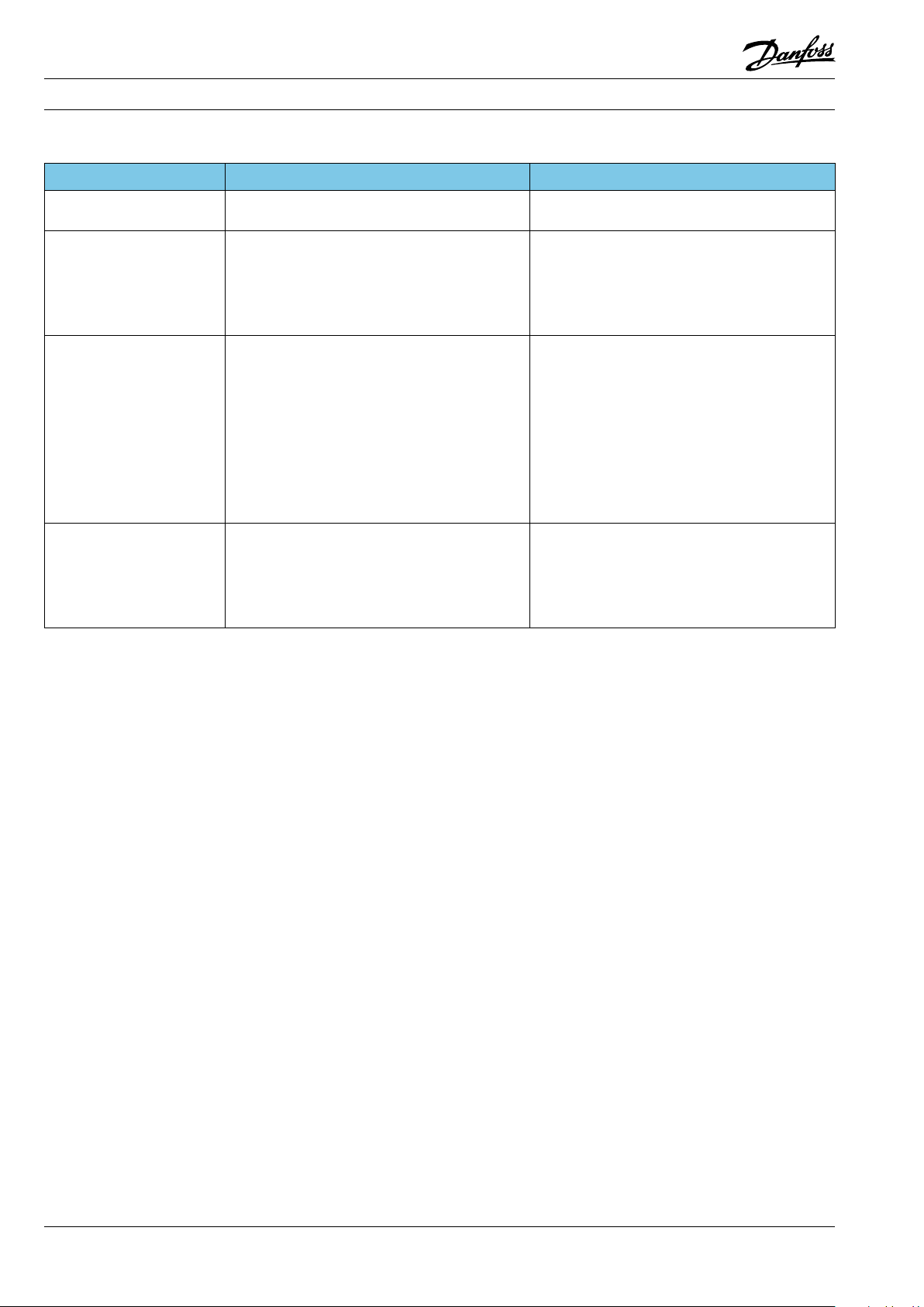
Fitters notes Trouble shooting - Fault location (Danfoss commercial refrigeration controls)
Fault location on the lter or sight glass
Symptom Possible cause Action
Sight glass indicator shows
yellow
Insucient evaporator
capacity
Bubbles in sight glass after
lter
Filter outlet side colder
than inlet side (can be iced
up)
* Rember to seal the old lter after removal.
Too much moisture in system. Replace lter drier*
Pressure drop across lter too high. Compare lter size with system capacity.
Replace lter drier*
Filter clogged. Replace lter drier*
Filter under-sized. Compare lter size with system capacity.
Replace lter drier*
Pressure drop across lter too high. Compare lter size with system capacity.
Replace lter drier*
Filter clogged. Replace lter drier*
Filter under-sized. Compare lter size with system capacity.
Replace lter drier*
Insucient sub-cooling. Check reason for insucient subcooling.
Do not charge refrigerant only because of
insucient sub-cooling.
Insucient refrigerant charge. Charge necessary refrigerant.
Pressure drop across lter too high. Compare lter size with system capacity.
Replace lter drier*
Filter clogged. Replace lter drier*
Filter under-sized. Compare lter size with system capacity.
Replace lter drier*
182 DKRCC.PF.000.G1.02 / 520H1459 © Danfoss A/S (AC-DSL/MWA), 10 - 2006
Page 39

Fitters notes Trouble shooting - Fault location (Danfoss commercial refrigeration controls)
Fault location on the KV pressure regulator
Symptom Possible cause Action
Room temperature
too high
Room temperature too low KVP evaporating pressure regulator set too low. Increase the setting of the evaporating pressure
Suction pressure hunts KVP evaporating pressure regulator too large. Replace evaporating pressure regulator with
Suction pressure too high KVC capacity regulator defective or set too high. Replace capacity regulator. Set capacity regulator
Condensing pressure
too high, air-cooled
condensers
Condensing pressure
too high, water-cooled
condensers
Crankcase pressure
regulator setting drift
Compressor discharge
pipe too hot
Temperature in receiver
too high
No subcooled liquid
KVP evaporating pressure regulator set too high. Reduce the setting of the evaporating pressure
regulator. The setting should be about 8-10 K
lower than required room temperature.
Remember to screw on protective cap after nal
setting.
Bellows leak in KVP evaporating pressure regulator. Slowly loosen protective cap.
If pressure or traces of refrigerant exist under the
cap, there is a leak in the bellows. Replace the
valve.
regulator. The setting should be about 8-10 K
lower than the required
room temperature. Remember to screw on protective cap after nal setting.
smaller size.
Remember to screw on the protective cap after
nal setting.
KVC capacity regulator too large. Replace capacity regulator with smaller size.
Remember to screw on protective cap after nal
setting.
at lower pressure.
Remember to screw on protective cap after nal
setting.
KVR condensing pressure regulator set too high. Set condensing pressure regulator at correct
pressure.
Remember to screw on protective cap after nal
setting.
Bellows in KVR condensing pressure regulator
might be leaking.
Slowly loosen protective cap. If pressure or traces
of refrigerant exist under the cap, there is a leak in
the bellows.
Replace valve.
Bellows leak in KVL crankcase pressure regulator. Slowly loosen protective cap. If pressure or traces
of refrigerant exist under the cap, there is a leak in
the bellows.
Replace the valve.
Probable bellows leak in KVC capacity regulator. Slowly loosen protective cap. If pressure or traces
of refrigerant exist under the cap, there is a leak in
the bellows.
Replace valve.
Hot gas quantity too large. If necessary, set the KVC capacity regulator at
lower pressure. An injection valve (e.g. TE2) can be
installed in the suction line.
KVD receiver pressure regulator set for too low a
pressure.
Set the receiver pressure regulator at a higher
pressure. It might also be necessary to increase the
setting of the condensing pressure regulator.
Bellows in KVD receiver pressure regulator might
be leaking.
Slowly loosen protective cap. If pressure or traces
of refrigerant exist under the cap, there is a leak in
the bellows.
Replace valve.
Trouble shooting
© Danfoss A/S (AC-DSL/MWA), 10 - 2006 DKRCC.PF.000.G1.02 / 520H1459 183
Page 40

Page 41

Fitters notes Trouble shooting - Fault location in refrigeration circuits with hermetic compressors
Contents Page
1.0 Compressor/system does not run (start) . . . . . . . . . . . . . . . . . . . . . . . . . . . . . . . . . . . . . . . . . . . . . . . . . . . . . . 187
2.0 The compressor/system runs, but with reduced refrigeration capacity. . . . . . . . . . . . . . . . . . . . . . . . . . 190
3.0 Power consumption too high. . . . . . . . . . . . . . . . . . . . . . . . . . . . . . . . . . . . . . . . . . . . . . . . . . . . . . . . . . . . . . . . . 193
4.0 Noise . . . . . . . . . . . . . . . . . . . . . . . . . . . . . . . . . . . . . . . . . . . . . . . . . . . . . . . . . . . . . . . . . . . . . . . . . . . . . . . . . . . . . . . . 195
© Danfoss A/S (AC-DSL/MWA), 10 - 2006 DKRCC.PF.000.G1.02 / 520H1459 185
Trouble shooting
Page 42

Notes
186 DKRCC.PF.000.G1.02 / 520H1459 © Danfoss A/S (AC-DSL/MWA), 10 - 2006
Page 43

Fitters notes Trouble shooting - Fault location in refrigeration circuits with hermetic compressors
1.0
Compressor/system
does not run (start)
1.1
Main switch drop-out Blown fuse
Short-circuiting to frame
Motor defect
Defective current lead-in
Electrical equipment
Compressor Compressor motor/motor protector mechanically blocked.
Overload
Voltage/frequency
Pressure irregularity
Refrigerant type
Pressure equalisation
Fan drop-out
High and low-pressure switches Mechanical defect
Incorrect connection
Incorrect dierential setting
Incorrect cutout setting
Pressure irregularity
Thermostat Mechanical defect
Incorrect connection
Dierential too small
Incorrect cutout value
If the main fuse blows, the cause must be found.
This will most often be a defect in the motor
windings or motor protector, short-circuiting to
frame or a burnt current lead-in which, in turn,
causes main fuse drop-out. If a compressor motor
refuses to start, always check the resistances
rst. All compressors have their main and start
windings located as shown in the sketch.
Resistance values are stated in the individual data
sheets.
1.2
1.3
As a rule, a motor protection is built into all
compressor motors. If the winding protector cuts
out the motor, due to the heat accumulated in
the motor the cut-out period can be relatively
long (up to 45 minutes). When the motor will
no longer run, resistance measurement will
conrm whether a motor protector has cut out
or whether a winding is defective. A mechanical
seizure in the compressor will show itself by
repeated start attempts accompanied by
high current consumption and high winding
temperatures that cause motor protector cutout.
Compressor overload can be recognised by the
compressor refusing to start or by starting and
then stopping again after a very short time (via
the motor protector). If the com-pressor is used
outside its allowed application limits the usual
result is overload. Application limits such as
voltage tolerances, frequencies, temperature/
pressure and refrige-rant type are given in the
individual data sheet. In systems not protected by
a high-pressure cut-out switch on the discharge
side, a fan motor which is defective or cut out
via a motor protector can lead to compressor
overload. Generally, the refrigerant quantity
must be determined precisely. In capillary tube
systems the most certain method is to take
temperature measurements on the evaporator
and suction line.
Am0_0075
Am0_0076
Trouble shooting
Am0_0077
© Danfoss A/S (AC-DSL/MWA), 10 - 2006 DKRCC.PF.000.G1.02 / 520H1459 187
Page 44

Fitters notes Trouble shooting - Fault location in refrigeration circuits with hermetic compressors
1.4
1.5
In systems with thermostatic expansion valve,
charging must be checked using a sight glass. In
both systems, the refrigerant quantity must be
less than the quantity that can be accommodated
in the free volume on the discharge side.
Am0_0078
Compressors for capillary tube systems are
usually equipped with a PTC LST starting
device. Starting via a PTC requires complete
pressure equalisation between the high and
low-pressure sides on every start. In addition,
before it can operate, the PTC requires a standstill
time of about 5 minutes to ensure that the
PTC component is cooled down in order to
achieve maximum starting torque. When a “cold”
compressor is started and the current is cut o
a short time after, conict can arise between the
PTC and the motor protector. Because the motor
retains heat, up to approx. 1 hour can elapse
before normal start is possible.
Am0_0079
1.6
1.7
1.8
In systems where pressure equalisation on
starting is not certain, the compressor must be
equipped with an HST starting device. This also
applies to capillary tube systems with a standstill
time of less than 5 minutes. Defective or incorrect
relays and starting capacitors can cause starting
problems or that the compressor is cut out via
the motor protector. Note the manufacturer’s
compressor data. If the starting device is thought
to be defective the whole equipment must
be replaced, including the relay and starting
capacitor.
The PTC (25 Ω for 220 V mains and approx. 5 Ω for
115 V mains) can be checked using an ohmmeter.
A starting relay can be checked with a lamp, see
sketch. The relay is in order if the lamp does not
light up when the relay is upright. The relay is also
in order if the lamp lights up when the relay is
upside down.
Am0_0080
Am0_0081
Am0_0082
188 DKRCC.PF.000.G1.02 / 520H1459 © Danfoss A/S (AC-DSL/MWA), 10 - 2006
Page 45

Fitters notes Trouble shooting - Fault location in refrigeration circuits with hermetic compressors
1.9
1.10
A starting capacitor can also be checked by
applying rated mains voltage to it for a few
seconds and then short-circuiting the leads. If
sparks appear, the capacitor is in order.
Am0_0083
In some markets, Danfoss oers condensing units
with combined high and low-pressure switches
that protect the compressor against excessive
pressure on the discharge side and too low
pressures on the suction side. If the high-pressure
switch has cut out the system, a check should
be made to see whether pressure irregularity is
occurring. If the low-pressure switch has cut out,
the cause can be insucient refrigerant amount,
leakage, evaporator icing and/or partial blockage
of the throttling device.
If there is no pressure irregularity on the high
or low-pressure sides, the pressure switch itself
must be checked. See also the chapter “Pressure
controls”.
1.11
The system can also cut out because of a
defective or incorrectly set/sized thermostat.
If the thermostat loses charge or if the
temperature setting is too high, the system will
not start. If the temperature dierential is set too
low, compressor standstill periods will be short
and there might be starting problems with an
LST starting device and shortened compressor
life with an HST starting device. The guideline for
pressure equalisation time using an LST starting
device is 5 to 8 minutes for refrigerators and 7 to
10 minutes for freezers.
If an HST starting device is used, the aim is
to keep the cut-in periods per hour as few as
possible. Under no circumstances must there
be more than ten starts per hour. See also the
chapter “Thermostats”.
Am0_0084
Am0_0085
Trouble shooting
© Danfoss A/S (AC-DSL/MWA), 10 - 2006 DKRCC.PF.000.G1.02 / 520H1459 189
Page 46

Fitters notes Trouble shooting - Fault location in refrigeration circuits with hermetic compressors
2.0
The compressor/system
runs, but with reduced
refrigeration capacity
2.1
2.2
Compressor Leakage
Pressure irregularity Blockage
Throttling device
Capillary tube/thermostatic expansion valve
Coking
Non-condensible gases
Moisture
Dirt
Fan defect
Refrigerant loss
Refrigerant overcharge
Icing
Static superheat setting
Orice size/diameter
Frequent causes of reduced refrigeration capacity
are coking, and copper plating which lead to
reduced life time of the compressor and burst
gaskets in the compressor valve system.
Coking occurs mainly as a result of moisture in
the refrigeration system. In high temperatures,
the presence of moisture also causes copper
plating on valve seats. The burst gaskets are the
result of an excessive condensing pressure and
excessively high short-lived pressure peaks >60
bar (liquid hammer).
Am0_0086
We recommend the installation of good quality
lter driers. If the lter material is of poor quality,
wear will occur which will not only cause the
partial blockage of capillary tube and the lter in
the thermostatic expansion valve, but it will also
damage the compressor (mainly seizure).
2.3
2.4
In general, commercial refrigeration systems
must be equippd with lters having a solid core,
e.g. type DML. See also the chapter “Filter driers &
sight glasses”.
The lter drier must be replaced after every
repair. When replacing a “pencil drier” (often used
in refrigerators) care must be taken to ensure
that the lter material used is suitable for the
refrigerant and that there is sucient material for
the application.
Poorly soldered joints can also cause system
blockage. Making good soldered joints is
conditional on using the correct soldering metal
containing the correct percentage of silver.
The use of ux should be limited and kept to as
minimum as possible.
Am0_0087
Am0_0088
Am0_0089
190 DKRCC.PF.000.G1.02 / 520H1459 © Danfoss A/S (AC-DSL/MWA), 10 - 2006
Page 47

Fitters notes Trouble shooting - Fault location in refrigeration circuits with hermetic compressors
2.5
2.6
Poorly soldered joints can also cause leakage
and thereby coking. In a refrigeration circuit the
proportion of non-condensible gases should
be kept below 2%, otherwise the pressure level
will rise. The main purpose of evacuation is
to remove non-condensible gases before the
refrigerant is charged. This also produces a drying
eect in the refrigeration system. Evacuation
can be performed either from both discharge
and suction sides, or from the suction side
only. Evacuation from both sides gives the best
vacuum. Evacuation from the suction side only
makes it dicult to obtain sucient vacuum
on the discharge side. Therefore, with onesided evacuation, intermediate ushing with
dry Nitrogen is recommended until pressure
equalisation is achieved.
Dirt on the condenser and a fan motor defect can
cause excessive condensing pressure and thereby
reduced refrigeration capacity. In such cases the
built-in high-pressure switch provides overload
protection on the condenser side.
Note: The built-in motor protector does not
give the compressor optimum protection if
the condensing pressure rises as a result of a
fan motor drop-out. The temperature of the
motor protector does not rise quickly enough
to ensure the protector cutout. This also applies
when the refrigerant quantity is greater than can
be accommodated in the free volume on the
discharge side.
Am0_0090
2.7
2.8
Am0_0091
It is important to determine the quantity of
refrigerant precisely – especially in capillary tube
systems. The guidelines are that the temperature
on the evaporator inlet must, as far as possible,
be the same as the temperature at its outlet, and
that as much superheating as possible must be
obtained between the evaporator outlet and the
compressor inlet. (The inlet temperature on the
compressor must be about 10 K less than the
condensing temperature).
Am0_0092
Overcharging of a refrigeration system equipped
with a thermostatic expansion valve becomes
critical when the charging quantity in liquid
condition is greater than can be accommodated
by the free volume in the receiver, i.e. the
condenser area is reduced and the condensing
pressure rises.
Trouble shooting
Am0_0093
© Danfoss A/S (AC-DSL/MWA), 10 - 2006 DKRCC.PF.000.G1.02 / 520H1459 191
Page 48

Fitters notes Trouble shooting - Fault location in refrigeration circuits with hermetic compressors
2.9
2.10
It is very seldom that there is too little refrigerant
in a system, unless leakage occurs. Irregular icing
on the evaporator is often a sign of insucient
refrigerant. This irregular icing does not only
reduce the refrigeration output, it can also give
problems in evaporator defrosting because the
defrost thermostat sensor does not register the
presence of ice. Therefore, precise determination
of the refrigerant charge is recommended as a
way of making sure that ice on the evaporator is
evenly distributed.
Am0_0094
The optimum system eciency is obtained when
a heat exchanger is tted to ensure subcooling:
about 5 K in systems with thermostatic expansion
valve and about 3 K in systems with capillary
tube. In systems with a thermostatic expansion
valve the suction and liquid lines must be
soldered together over a distance of 0.5 to 1.0 m.
In capillary tube systems the capillary tube and
suction line must be soldered together for 1.5 to
2.0 m.
Am0_0095
192 DKRCC.PF.000.G1.02 / 520H1459 © Danfoss A/S (AC-DSL/MWA), 10 - 2006
Page 49
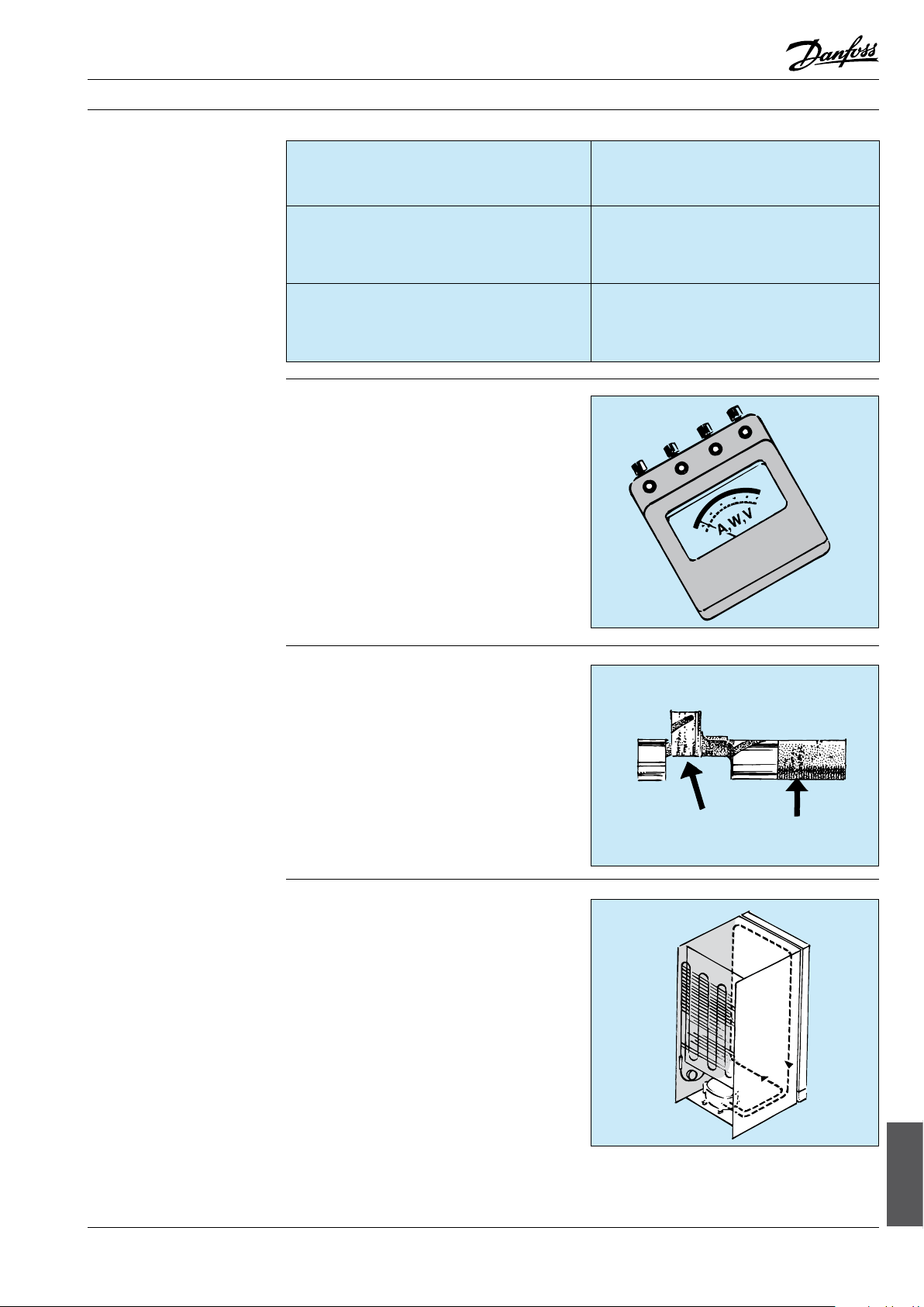
Fitters notes Trouble shooting - Fault location in refrigeration circuits with hermetic compressors
3.0
Power consumption
too high
3.1
Compressor Signs of compressor wear
Pressure irregularity Blockage
Overload Application limits exceeded
Motor defect
Reduced refrigeration capacity
Compressor cooling
Non-condensible gases
Moisture
Dirt
Fan defect
Voltage/frequency
Pressure irregularity
Temperature
Refrigerant type
Pressure irregularity and overload often cause
compressor defects that show themselves in the
form of increased power consumption. Refer to
the previous pages for information on problems
with pressure irregularity and compressor
overload seen from the system side.
Excessive evaporating and condensing pressures
cause compressor motor overload which leads to
increased power consumption. This problem also
arises if the compressor is not suciently cooled,
or if extreme overvoltage occurs. Undervoltage
is not normally a problem in Western Europe
because here the voltage rarely drops below
198 V.
Am0_0096
3.2
3.3
Constant overload will give signs of wear
in compressor bearings and valve systems.
Overload that causes frequent winding protector
cutouts can also produce an increased number of
electrical drop-outs.
In cases where the application limits are
exceeded, the system must be adapted. For
example, by the use of a thermostatic expansion
valve with an MOP that will limit the evaporating
pressure, a pressure regulator, or a condensing
pressure regulator. See also the chapter
“Thermostatic expansion valves” and the chapter
“Pressure regulators”.
Static cooling (in certain circumstances an
oil cooler) is sucient for most household
refrigeration appliances, provided that the
clearances specied by the manufacturer are
maintained, especially where a built-in appliance
is concerned.
Am0_0097
Am0_0098
© Danfoss A/S (AC-DSL/MWA), 10 - 2006 DKRCC.PF.000.G1.02 / 520H1459 193
Trouble shooting
Page 50

Fitters notes Trouble shooting - Fault location in refrigeration circuits with hermetic compressors
3.4 Commercial equipment should be fan-cooled.
The normal recommended air velocity across
condenser and compressor is 3 m/s.
Am0_0099
3.5
A further recommendation is regular service on
the refrigeration system, including cleaning of
the condenser.
Am0_0100
194 DKRCC.PF.000.G1.02 / 520H1459 © Danfoss A/S (AC-DSL/MWA), 10 - 2006
Page 51

Fitters notes Trouble shooting - Fault location in refrigeration circuits with hermetic compressors
4.0
Noise
4.1
Compressor Pressure circuit
Oil level
Clearance: piston/cylinder
Valve system
Fan Deformed fan blades
Bearing wear
Baseplate
Valves Whistling« from thermostatic expansion valves
»Chatter« from solenoid and check valves
System noise Liquid noise
(mainly in evaporator)
Installation Piping
Compressor, fan and condenser brackets
Danfoss compressors and condensing units
do not normally give rise to complaints about
noise. The noise level of compressors and, above
all, fans is well in agreement with the demands
made by the market. If occasional complaints are
received, they usually arise from installation or
system errors.
4.2
4.3
Am0_0101
The rare noise problems that do occur are mostly
because of production faults, e.g. discharge line
touching the compressor housing, oil level too
high/low, too much clearance between piston
and cylinder, faulty assembly of the valve system.
Such noise is easy to diagnose with a screwdriver
used as a "stethoscope".
Am0_0102
System noise is a critical factor in household
appliances. Here, liquid noise at the evaporator
inlet is characteristic. On the system side it is
dicult to remedy this problem because what
is involved is a mass produced equipment. If
the lter is mounted vertically, it might help to
mount it horizontally instead. However, it should
be remembered that noise can be amplied by
structure, e.g. with a built-in appliance. In such a
situation, the manufacturer should be contacted.
Trouble shooting
Am0_0103
© Danfoss A/S (AC-DSL/MWA), 10 - 2006 DKRCC.PF.000.G1.02 / 520H1459 195
Page 52

Fitters notes Trouble shooting - Fault location in refrigeration circuits with hermetic compressors
4.5
4.6
To prevent noise transfer, pipework should not
be allowed to touch the compressor, the heat
exchanger or the side walls.
When installing a compressor, the ttings and
grommet sleeves supplied must be used to avoid
the rubber pads being compressed so much that
they lose their noise-suppression properties.
Am0_0104
Fans are used mostly in commercial refrigeration
systems. Noise will be generated if the fan blades
become deformed or touch the heat exchanger
ns. Worn bearings also produce a great deal of
noise. Additionally, the fan unit must be rmly
secured so that it does not move in relation
to its mounting bracket. Normally, fans have a
higher noise level than compressors. In some
circumstances, it is possible to reduce the noise
level by installing a smaller fan motor, but this
can only be recommended when the condenser
area is over-sized.
4.7
Am0_0105
If the noise comes from the valves, the cause
is usually incorrect sizing. Solenoid and check
valves must never be sized to suit the pipe
connections, but in accordance with the kv value.
This ensures the min. pressure drop necessary to
open the valve and keep it open without valve
"chatter". Another phenomenon is "whistling"
in thermostatic expansion valves. Here a check
should be made to ensure that the size of the
orice corresponds to the system characteristics
and that above all there is sucient liquid subcooling ahead of the expansion valve [approx. 5 K].
Am0_0106
196 DKRCC.PF.000.G1.02 / 520H1459 © Danfoss A/S (AC-DSL/MWA), 10 - 2006
Page 53

Fitters notes Trouble shooting - Fault location overview (Danfoss compressors)
Contents Page
General . . . . . . . . . . . . . . . . . . . . . . . . . . . . . . . . . . . . . . . . . . . . . . . . . . . . . . . . . . . . . . . . . . . . . . . . . . . . . . . . . . . . . . . . . 199
Fault location. . . . . . . . . . . . . . . . . . . . . . . . . . . . . . . . . . . . . . . . . . . . . . . . . . . . . . . . . . . . . . . . . . . . . . . . . . . . . . . . . . . . 199
Electrical compressor quick check . . . . . . . . . . . . . . . . . . . . . . . . . . . . . . . . . . . . . . . . . . . . . . . . . . . . . . . . . . . . . . . . 199
Check main and start winding. . . . . . . . . . . . . . . . . . . . . . . . . . . . . . . . . . . . . . . . . . . . . . . . . . . . . . . . . . . . . . . . . . . . 200
Check protector . . . . . . . . . . . . . . . . . . . . . . . . . . . . . . . . . . . . . . . . . . . . . . . . . . . . . . . . . . . . . . . . . . . . . . . . . . . . . . . . . 200
Check relay. . . . . . . . . . . . . . . . . . . . . . . . . . . . . . . . . . . . . . . . . . . . . . . . . . . . . . . . . . . . . . . . . . . . . . . . . . . . . . . . . . . . . . 200
Check PTC. . . . . . . . . . . . . . . . . . . . . . . . . . . . . . . . . . . . . . . . . . . . . . . . . . . . . . . . . . . . . . . . . . . . . . . . . . . . . . . . . . . . . . . 201
Fault location (Most common fault reasons, detectable before dis-mounting compressor) . . . . . . . . . 202
© Danfoss A/S (AC-DSL/MWA), 10 - 2006 DKRCC.PF.000.G1.02 / 520H1459 197
Trouble shooting
Page 54

Notes
198 DKRCC.PF.000.G1.02 / 520H1459 © Danfoss A/S (AC-DSL/MWA), 10 - 2006
Page 55

Fitters notes Trouble shooting - Fault location overview (Danfoss compressors)
General
This section is directed especially to the service
network, for household appliances and similar. It
deals mainly with PL, TL, NL and FR compressors
for 220-240V.
For detailed information on compressors see the
data sheets.
Compressors type PL, TL, NL, FR and partly SC
are equipped with a PTC starting device (g. 1)
or a relay and start capacitor (g. 2). The motor
protector is built into the windings.
In the event of a start failure, with a cold
compressor, up to 15 minutes can elapse before
the protector cuts out the compressor.
When the protector cuts out and the compressor
is warm, it can take up to 1 hour before the
protector cuts in the compressor again.
The compressor must not be started without the
electrical equipment.
Fig. 1: PTC starting device
Am0_0069
Fig. 2: Starting relay
Fault location
Electrical compressor
quick check
Before beginning systematic fault location, a
good rule is to cut the supply voltage for at least
5 minutes. This ensures that the PTC starting
device has cooled o and is ready for start.
A voltage drop or blackout within the rst
minutes of a pull down of the appliance with cold
compressor, can lead to an interlocking situation.
To avoid unneccessary protector operation and
consequent waiting time, it is important to carry
out fault location in the sequence given below.
Tests are made according to desriptions on
following page.
Remove electrical equipment
Check electrical connection between main
and start pins of compressor terminal
Check electrical connection between main
and common pins of
Compressor terminal
Replace compressor, if above connection
checks failed
Else, replace electrical equipment
Am0_0070
A compressor with PTC can not start at non
equalized pressure and the PTC does not cool
down so fast. It can take more than 1 hour until
the appliance then operates normally again.
If the compressor still does not operate, most
probably it is no electrical compressor failure. For
more detailed fault location, see the tables.
Trouble shooting
© Danfoss A/S (AC-DSL/MWA), 10 - 2006 DKRCC.PF.000.G1.02 / 520H1459 199
Page 56

Fitters notes Trouble shooting - Fault location overview (Danfoss compressors)
Check main and
start winding
Resistance between pins M (main) and S (start)
on compressor terminals is measured with an
ohm-meter, see g. 3.
Connection → Main and start windings normally OK → Replace relay
No connection → Main or start winding defective → Replace compressor
At cold compressor (ca. 25°C) the values are
ca. 10 to 100 Ohm for 220-240 V compressors.
For partial short circuit detection, exact values
are needed from data sheets of the specic
compressor, which can be found on the Danfoss
Compressors homepage.
Fig. 3: Compressor terminals Fig. 4: Windings and protector
Am0_0071
Am0_0072
Check protector
Resistance between pins M (main) and
C (common) on compressor terminals is
measured with an ohm-meter, see g. 3 and 4.
Connection → Protector OK
No connection → Compressor cold → Protector defective → Replace compressor
Compressor hot → Protector could be OK, but cut out → Wait for reset
Check relay Remove relay from compressor.
Measure connection between connectors 10
and 12 (see g. 5):
No connection → Relay defective → Replace relay
Measure connection between connectors 10
and 11:
In normal vertical position (like mounted,
solenoid upward):
Connection → Relay defective → Replace relay
No connection → OK
In top-down position (solenoid downward):
Connection → OK
No connection → Relay defective → Replace relay
200 DKRCC.PF.000.G1.02 / 520H1459 © Danfoss A/S (AC-DSL/MWA), 10 - 2006
Page 57

Fitters notes Trouble shooting - Fault location overview (Danfoss compressors)
Check PTC
Remove PTC from compressor.
Shake by hand. Pin C can slightly rattle.
Internal rattle noise
(except pin C) →
PTC defect → Replace PTC
Measure resistance between pins M and S,
see g. 6.
Resistance value between 10 and 100 Ohm
at room temperature for 220 V PTC.
Connection → PTC working → OK
No connection → PTC defect → Replace PTC
Fig. 5: Relay connections Fig. 6: PTC connections (backside)
Am0_0073
Am0_0074
© Danfoss A/S (AC-DSL/MWA), 10 - 2006 DKRCC.PF.000.G1.02 / 520H1459 201
Trouble shooting
Page 58

Fitters notes Trouble shooting - Fault location overview (Danfoss compressors)
Fault location
Most common fault reasons, detectable before dis-mounting compressor.
Customer
claim
No/reduced
cooling
First
analysis
Compressor
does not run
Compressor
runs 100%
Possible cause
Compressor gets no or bad
power supply
Defective relay
Defective start cap
PTC defective
Compressor with PTC can
not start at pressure
difference
PTC defective
Relay defective
Compressor
overloaded
Defective motor
windings
Defective protector
Mechanically blocked
compressor
No or low refrigerant
charge
Check
Voltage at plug and fuse
Aplicance energized
Thermostat function
Cables and connections in appliance
Voltage at compressor terminals
Relay function by shaking to hear if
armature is working
Start capacitor function
PTC by shaking
PTC resistance 10 to 100 Ohm between
M and S pin
Stop time long enough for pressure
equalization
PTC resistance 10 to 100 Ohm between
M and S pin
Relay function by shaking, to hear moving
of armature
Condenser pressure and ventilation
Ambient temperature too high according
to type label of appliance
Check winding resistances
Check protector with ohmmeter
Start with proper starting equipment,
voltage and conditions,
windings and protector OK
Recharge and search for leaks
Activity
(depends on result)
Replace relay
Replace start capacitor
Replace if noise appears
Replace PTC, if not 10 to
100 Ohm
Adjust thermostat difference
Replace PTC
Replace relay and capacitor
Ensure proper ventilation
Replace compressor
Replace compressor
Replace compressor
Ensure leakfree system and
proper charge
Compressor
runs on/off
Too high ambient
temperature
Too high condensing
temperature
Capillary partly blocked
Valves coked or damaged
Thermostat not OK
Wrong refrigerant charge
Ice block built up on
evaporator
Compressors trips on
motor protector
Ambient temperature according to type
label of appliance
Condenser and compressor ventilation
Recharge and search for leaks, measure
suction pressure. Capillary blocked, if
pressure very low
Recharge and search for leaks
Thermostat type and function
Recharge and search for leaks
Check for ice on evaporator
Thermostat function and settings
Internal no-frost fan function
Compressor load, compressor and
condenser ventilation
Compressor voltage supply for
minimum 187 V
Compressor voltage supply for drop outs.
Check thermostat and appliance cables for
loose connections
Motor windings resistance for partly short
circuit or earth connection
Replace drier
Ensure proper ventilation and
wall distance
Replace compressor, if still not
cooling properly
Replace thermostat
Ensure leakfree system and
proper charge,
Replace drier
Defrost properly
Replace thermostat
Ensure proper ventilation and
wall distance
Ensure proper power supply
Fix all connections
Replace compressor
202 DKRCC.PF.000.G1.02 / 520H1459 © Danfoss A/S (AC-DSL/MWA), 10 - 2006
Page 59

Fitters notes Trouble shooting - Fault location overview (Danfoss compressors)
Fault location
(continued)
Customer
claim
Noise
Fuses are blown
by appliance
First analysis
Rattle or
humming
Banging at start
or stop of
compressor
Relay clicking
frequently after
start
Short circuit in
appliance
Short circuit in
compressor
Fuse blows at
compressor start
Starting capacitor
exploded
Starting relay cap
blown off
Possible cause
Tube touching cabinet
Compressor touching
cabinet
Broken internal suspension
spring or discharge tube
Resonance
Fan noise
Compressor block hitting
housing internally
Compressor overloaded
Relay defective
Defective cabling in
appliance
Defective thermostat
Ground connection
Defective terminals
Short circuit between
cables at terminals
Short circuit in
compressor motor
Supply voltage too low
Fuse loaded by too many
appliances
Resettable fuse too quick
acting
Partly short circuit to earth
Defective relay
Wrong relay type
Extremely many starts and
stops of compressor
Short circuit in compressor
motor
Check
Tube placing
Compressor mounting and rubber feet
Listen to compressor with screw-driver
against compressor with edge and to your
ear with grip
Find vibrating mounting parts
Vibration of fan or fan mounting
Compressor overload by pressure
Fan function
Refrigerant charge
Pressure equalization before start and number of on/off cycles
Ambient temperature according to type
label
Ventilation to compressor and
condenser. Check fan function
Right relay type for compressor
All connecting cables and power supply
cord for loose connections, short circuits
Thermostat connections
Resistance from line/neutral to earth
For burns on the terminal pins
Connectors and cables at compressor
Resistance values in windings
Resistance between terminals and earth
Supply voltage at compresor start >187 V
Total fuse load
Fuse load and type
Resistance between terminals and earth
Relay function by shaking, to hear moving
of armature
Relay type
Relay type
Thermostat defect or differences too small
Compressor motor resistances
Activity
(depends on result)
Bend tube to their right place,
carefully
Place rubber feet and
mounting accessories correctly
Replace compressor, if abnormal sounds
Place or fix correctly
Fix fan and blade, replace, if
defective
Clean condenser if dusty. Make
sure, that ventilation gaps for air
circulation are satisfactory
Recharge, if too high
Adjust thermostat, if stop time
less than 5 min
Take appliance out of function,
if ambient too hot
Clean condenser if dusty. Make
sure, that ventilation gaps for air
circulation are satisfactory
Replace relay, if wrong
Fix connections properly
Fix connections properly
Replace electrical
accessories
Insulate cables and
connectors
Replace compressor, if short
circuited
Connect applaince to
different fuse
If possible replace by slightly
slower type
Replace compressor, if short
circuited
Replace relay and capacitor
Replace relay and cap
Replace relay and cap
Adjust or replace thermostat
Replace compressor
© Danfoss A/S (AC-DSL/MWA), 10 - 2006 DKRCC.PF.000.G1.02 / 520H1459 203
Trouble shooting
 Loading...