

Page 1

User Guide
Easy and fast
Apply the MCXWeb tool with your MCX
To ensure that you correctly install your MCXWeb please follow this
user guide
www.danfoss.com/mcx
Page 2

User Guide | MCXWeb
Table of Contents
1. Introduction ........................................................................................... 3
2. MCXWeb components ....................................................................... 3
3. MCXWeb connections ........................................................................ 5
4. Web Server and MCX Update...........................................................6
4.1 Web server firmware update (xport) .................................. 6
4.2 Web Server software interface update (Web pages) ..... 6
4.3 MCX061V-MCX152V BIOS Update ...................................... 7
4.4 MCX061V-MCX152V Software Application Update ....... 7
5. Web Server User Guide ....................................................................... 8
5.1 Login ............................................................................................... 8
5.2 Main buttons ............................................................................... 9
5.3 Network Overview (home page) ........................................ 10
5.4 History .......................................................................................... 10
5.5 Alarms ..........................................................................................11
5.6 Configuration ............................................................................11
5.6.1 Configuration network ................................................12
5.6.2 Configuration Template & Files ................................13
5.6.2.1 Create the application template
with MCXShape ............................................................ 14
5.6.3 Configuration Users .....................................................15
5.6.4 Configuration System ..................................................15
5.6.4.1 Network .............................................................. 15
5.6.4.2 NTP ....................................................................... 16
5.6.4.3 Site ........................................................................ 16
5.6.4.4 Reboot ................................................................17
5.6.5 Configuration Update ................................................18
5.6.5.1 Application Update ........................................18
5.6.5.2 BIOS Update ...................................................... 18
5.6.6 Configuration History .................................................. 19
5.7 Device pages..............................................................................20
5.7.1 Device Overview ........................................................... 20
5.7.1.1 Customization of the Overview page ...... 21
5.7.2 Device Details ................................................................. 22
5.7.3 Device Alarms .................................................................23
5.7.4 Device Graphs ................................................................ 23
5.7.5 Device Back-up ..............................................................24
5.7.6 Device Restore ...............................................................24
5.7.7 Device Info ....................................................................... 25
6. MCXWeb Simulator ...........................................................................26
7. Appendix - Application template XML structure ....................28
© Danfoss | ADAP-KOOL® | 2017.07 2 | DKRCC.PS.RI0.Z1.02 |
Page 3
User Guide | MCXWeb
1. Introduction
2. MCXWeb components
MCXWeb is the online tool used to monitor software applications running into one or
more MCX devices connected in a CANbus network.
To monitor MCX devices using the MCXWeb you will need to have at least one MCX061V
or MCX152V device in the CANbus network, as these are the MCX models that supports
Web Server and an Ethernet connection.
The MCXWeb tool can also be used as a simulator for MCX software applications running
on a PC for testing and debugging.
IMPORTANT NOTE.
You can use MCXWeb with popular browsers like Chrome, Firefox, and Safari. Using it with
Internet Explorer is not recommended.
This manual refers to the following firmware version or later:
Web Server interface: 2v08
Web Server firmware: 2v23
MCX061V-MCX152V BIOS: 2v22
© Danfoss | ADAP-KOOL® | 2017.07
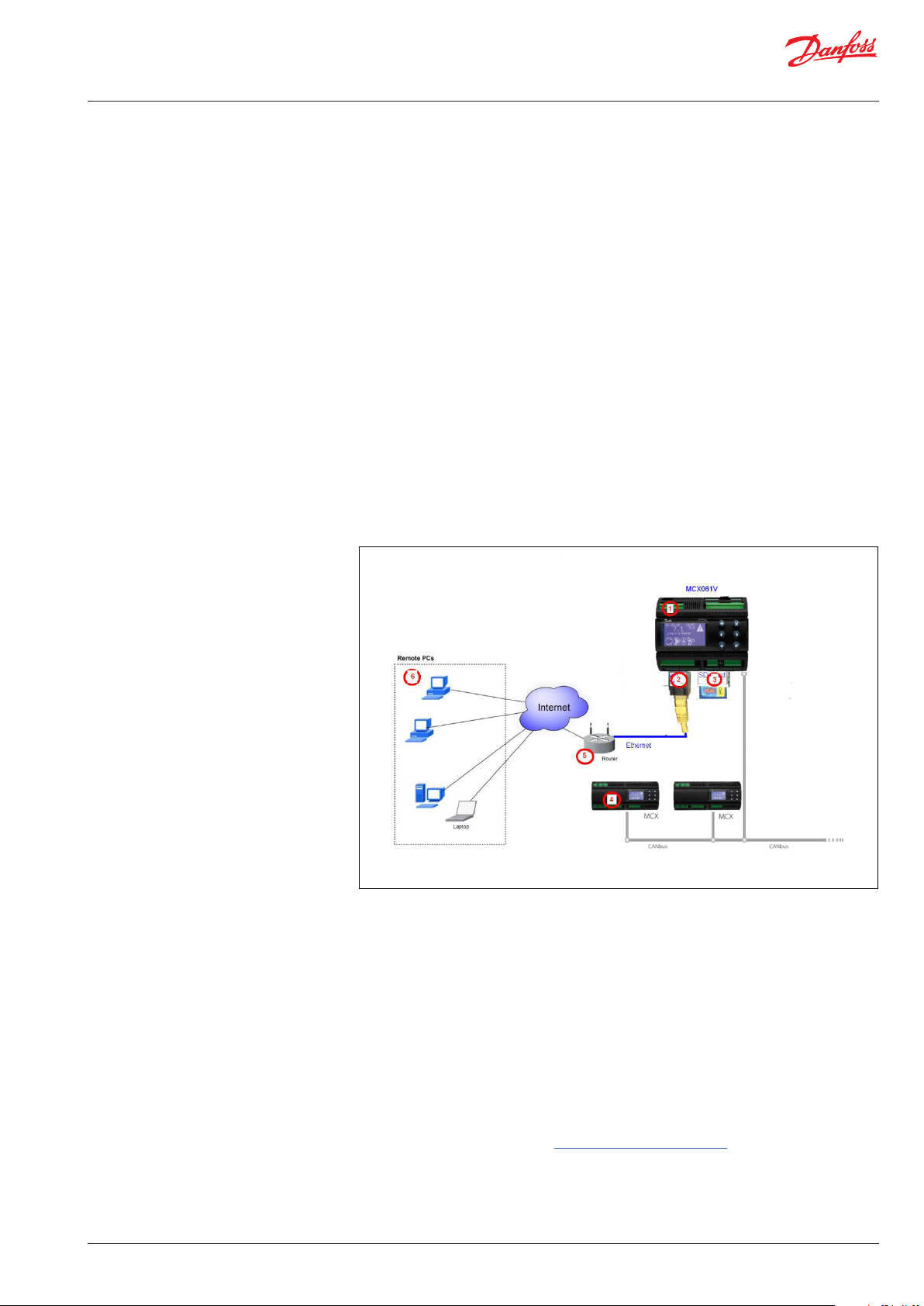
1. MCX061V and MCX152V are the MCX models with Web Server included.
Like all other MCX models, MCX061V and MCX152V are fitted with a BIOS and can run
application software.
2. Web Server is the software tool included with MCX061V and MCX152V, providing the
user with web pages that are displayed on a browser on remote PCs (6).
This service needs the following two software elements: Web Server firmware (xport
BIOS) and software interface (web pages).
- The Web Server firmware is the file xport_pro.romz
MCX061V and MCX152V are provided with Web Server’s firmware already installed
and should be upgraded only in case of special needs (see Paragraph 4.1 Web Server
firmware update).
The files needed to upgrade Web Server’s firmware (BIOS) are included in the MCXWeb update pack available at http://www.danfoss.com/mcx
DKRCC.PS.RI0.Z1.02 | 3
Page 4
User Guide | MCXWeb
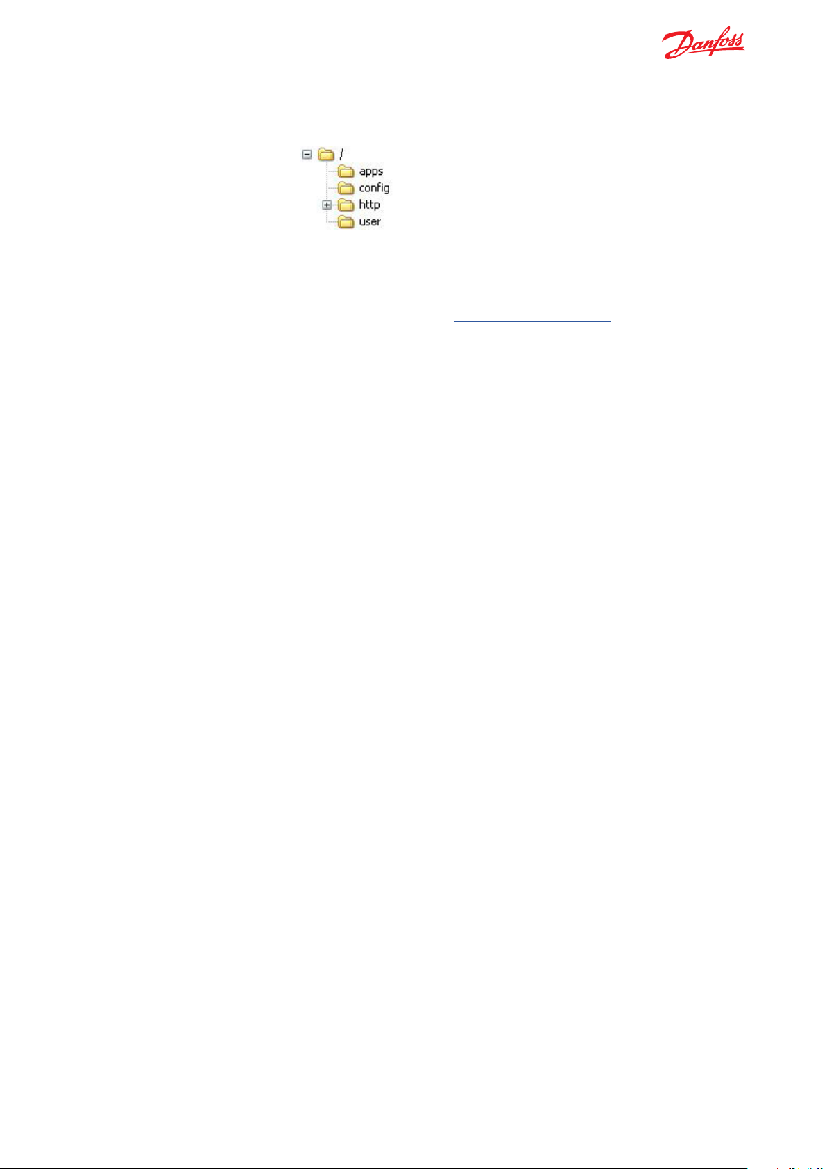
- The software interface is the set of the files in the following folders present in the root
of the server:
The MCX061V and MCX152V are provided with the Web Server software interface
already installed and should be upgraded only in case of special needs (see paragraph
4.2 Web Server software interface update).
All the files needed to upgrade Web Server’s software interface are included in MCXWeb update pack available at http://www.danfoss.com/mcx
The Web Server software interface includes the folders containing web pages and
additional files, for example, the software applications and templates used to configure the MCX present in the MCX CANbus network.
The configuration files should be added or upgraded every time a new MCX device
is added to the CANbus network or when there is an upgrade in the MCX firmware or
software (see Paragraph 5.6.1, Configuration Network).
3. A memory card is a hardware component used to upgrade the firmware and software of
Web Server and of the MCX, and to store log data.
4. MCX devices can be connected via CANbus to the MCX061V and MCX152V, which can
be used as web interfaces for all the MCX present in the CANbus network. Each MCX
is provided with its firmware (BIOS) and software application. MCX061V and MCX152V
must be configured with a template file for each MCX connected, representing the list of
variables involved in the communication.
5. A router is a device that connects MCX Web Server to the Internet
6. Remote PCs are the computers where MCXWeb pages are displayed through popular
browsers like Chrome, Firefox, and Safari. Using Internet Explorer is not recommended.
© Danfoss | ADAP-KOOL® | 2017.07 4 | DKRCC.PS.RI0.Z1.02 |
Page 5
User Guide | MCXWeb
3. MCXWeb connections
To start using MCXWeb, the first step is identifying the MCX061V or MCX152V in the local
network supporting the web server. There are two alternative options.
1) Enter in the BIOS menu of MCX061V or MCX152V by pressing and releasing the X and
ENTER key at power up.
Configure the TCP/IP settings by navigating to the “GEN SETTINGS” – “TCP/IP” screen.
You can manually assign the IP address or get it dynamically from the network via
DHCP.
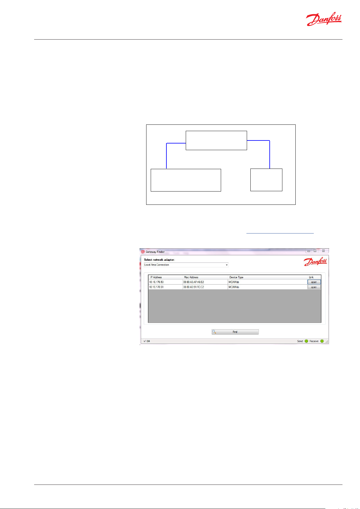
2) Realize a small local network as in Figure
LAN
MCX061V/MCX152V
IP = Auto
(DHCP enabled by factory default)
Ethernet Router
Server DHCP=ON
LAN
PC
IP = Auto
(DHCP)
Run the Gateway Finder program available at http://www.danfoss.com/mcx to find the
IP address of your MCX061V or MCX152V:
Using the Gateway Finder you get the IP address and MAC addresses of any MCX061V or
MCX152V connected to the LAN.
You can then establish a connection with MCX Web Server through a web browser or an
FTP client.
For the description of the web pages accessible through the web browser, see Paragraph
5, Web Server User Guide.
The FTP client is used to update the web server elements when needed. See Paragraph 4,
Web Server and MCX Update.
© Danfoss | ADAP-KOOL® | 2017.07
DKRCC.PS.RI0.Z1.02 | 5
Page 6
User Guide | MCXWeb
4. Web Server and MCX Update
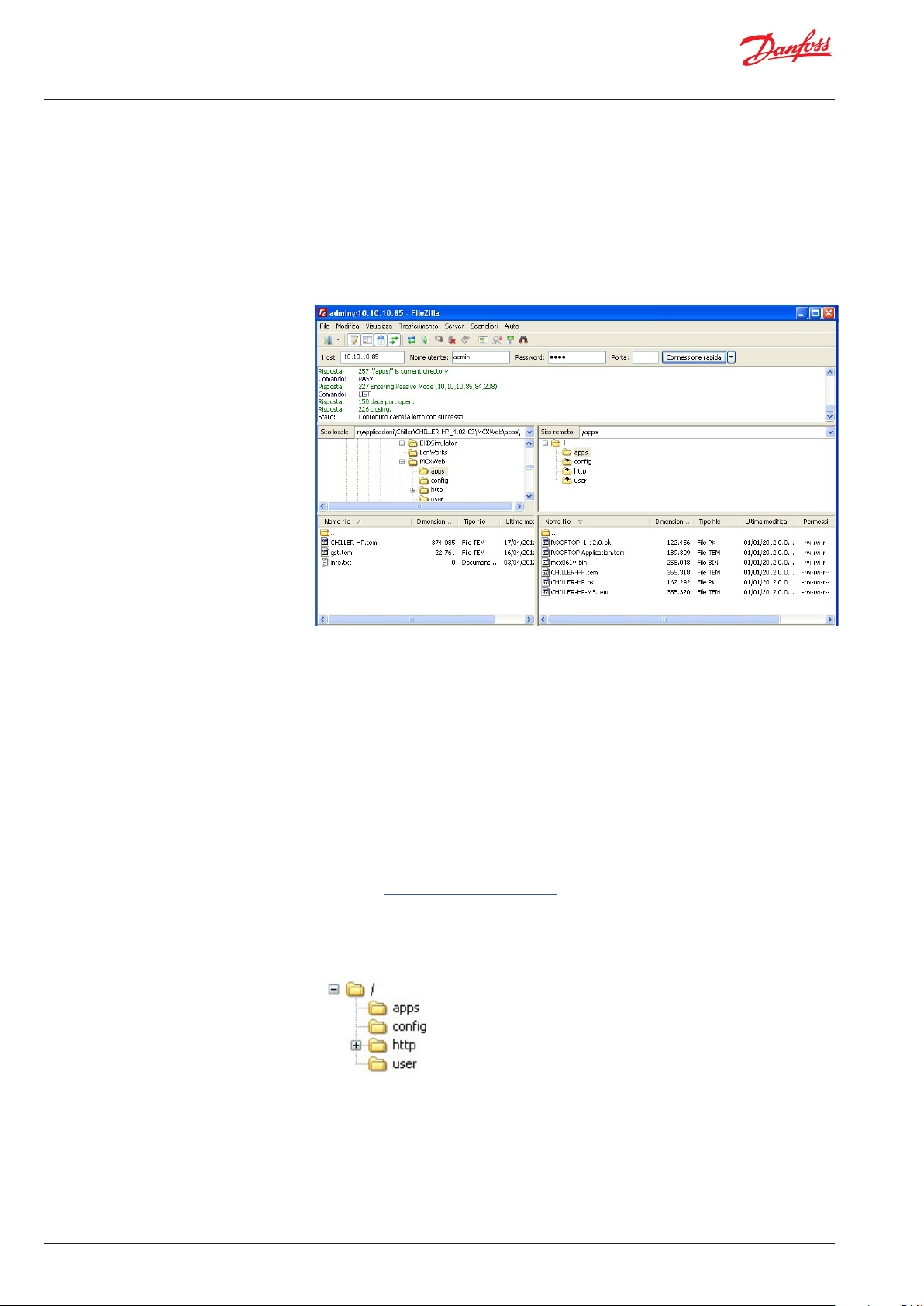
To update Web Server’s elements, use a FTP client. We suggest using FileZilla.
See Paragraph 3, MCXWeb Connection on how to establish a connection.
The parameters to configure the FTP client are as follows:
Host: MCX IP Address (e.g. 192.168.1.xxx)
Username: admin (Username is case sensitive)
Password: PASS (Password is case sensitive)
4.1 Web Server Firmware Update (xport)
4.2 Web Server Software Interface Update (web pages)
Establish the FTP connection with MCX Web Server as described in Paragraph 3, MCXWeb
connection.
To update MCX Web Server’s firmware, copy the file xport_pro.romz in the root of MCX
Web Server. The update procedure starts automatically after copying the files.
NOTE. The file will be automatically removed during the process.
WARNING: DO NOT power off the MCX061V/MCX152V for 2 minutes after the update.
If you have executed the Web Server firmware update as described in the previous
paragraph, wait two minutes from the start of that procedure before proceeding with
the Web Server software interface update.
To update the Web Server software interface, you will need the MCXWeb update pack
available at http://www.danfoss.com/mcx.
- Establish the FTP connection with MCX Web Server as described in Paragraph 3,
MCXWeb connection.
- Remove all the files and folders present on MCX Web Server
- Copy all the following folders, which the software interface is made of, in the root of
MCX Web Server.
WARNING: do not copy the Web Server firmware (romz file) with the software interface files,
otherwise the firmware update process will start (see the previous paragraph) and the web
pages will not be updated. If this happens, you must copy the folder of the wep pages in the
root of the MCX Web Server again two minutes after copying the firmware update.
WARNING: after an update operation, MCX Web Server may automatically run a defrag
operation to optimize space and performance; this operation makes the MCX Web Server
inaccessible for few minutes without any visible signal.
© Danfoss | ADAP-KOOL® | 2017.07 6 | DKRCC.PS.RI0.Z1.02 |
Page 7

User Guide | MCXWeb
4.3 MCX061V-MCX152V BIOS Update
4.4 MCX061V-MCX152V Software Application Update
The update for the MCX061V-MCX152V BIOS follows the same procedure of all the other
MCX models.
You can update via the CANbus using the MMYMYK or via serial communication using a
PC and a USB/485 converter.
In addition to the usual options, with MCX061V and MCX152V it is also possible to update
the BIOS via memory card and via web pages.
To update the BIOS via memory card, the procedure is as follows:
- copy the file mcx061v.bin or mcx152v.bin (the name is case sensitive) in the root of a
memory card
- switch off the MCX061V or MCX152V
- insert the memory card into the MCX slot
- switch on the MCX
The BIOS updating procedure will start automatically and the MCX display will show the
BIOS splash screen.
To update the BIOS via the web, follow the instructions in Paragraph 5.6.5.2, BIOS Update.
You can also update the BIOS of the MCX connected through CANbus to the MCX061VMCX152V using web pages.
The file needed to upgrade the BIOS is available in the BIOS
pack at http://www.danfoss.com/mcx
Updates to the application software running on MCX061V or MCX152V follow the same
procedure as all other MCX models.
You can update via the CANbus using the MMYMYK or via serial communication using a
PC and a USB/485 converter.
In addition to the standard update methods, MCX061V and MCX152V can also be
updated using an application, a memory card and web pages.
To update the application software via memory card, the procedure is as follows:
- copy the file app.pk (the name is case sensitive) in the root of a memory card
- switch off the MCX
- insert the memory card into the MCX slot
- power on the MCX.
The application will be automatically copied from memory to the MCX061V or MCX152V
and executed.
To update the application software using the web pages, follow the instructions in Paragraph
5.6.5.1, Application Update. When updating with web pages, you can also update the MCX’s
application software connected through the CANbus to the MCX061V-MCX152V.
© Danfoss | ADAP-KOOL® | 2017.07
DKRCC.PS.RI0.Z1.02 | 7
Page 8
User Guide | MCXWeb
5. Web Server User Guide
5.1 Login
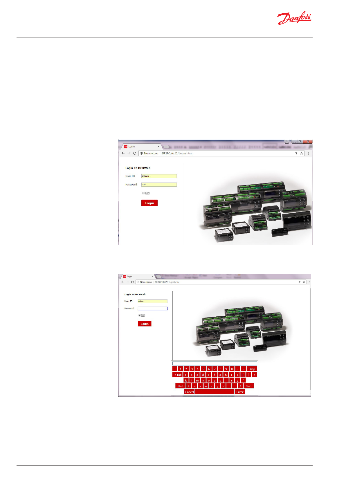
Launch an internet browser from the PC connected to the local network and type the IP
of the MCX061V or MCX152V (see Paragraph 3, MCXWeb Connection) in the address bar.
WARNING. You can use popular browsers like Chrome, Firefox, and Safari. Using Internet
Explorer is not recommended.
Enter your user name and password to log in to the MCXWeb interface
User name and password are defined in Configuration > Users. By default, they are admin
and PASS.
If you are using a virtual keyboard (e.g. for touch screens) check the box beside the keyboard
icon under the password field
© Danfoss | ADAP-KOOL® | 2017.07 8 | DKRCC.PS.RI0.Z1.02 |
Page 9
User Guide | MCXWeb
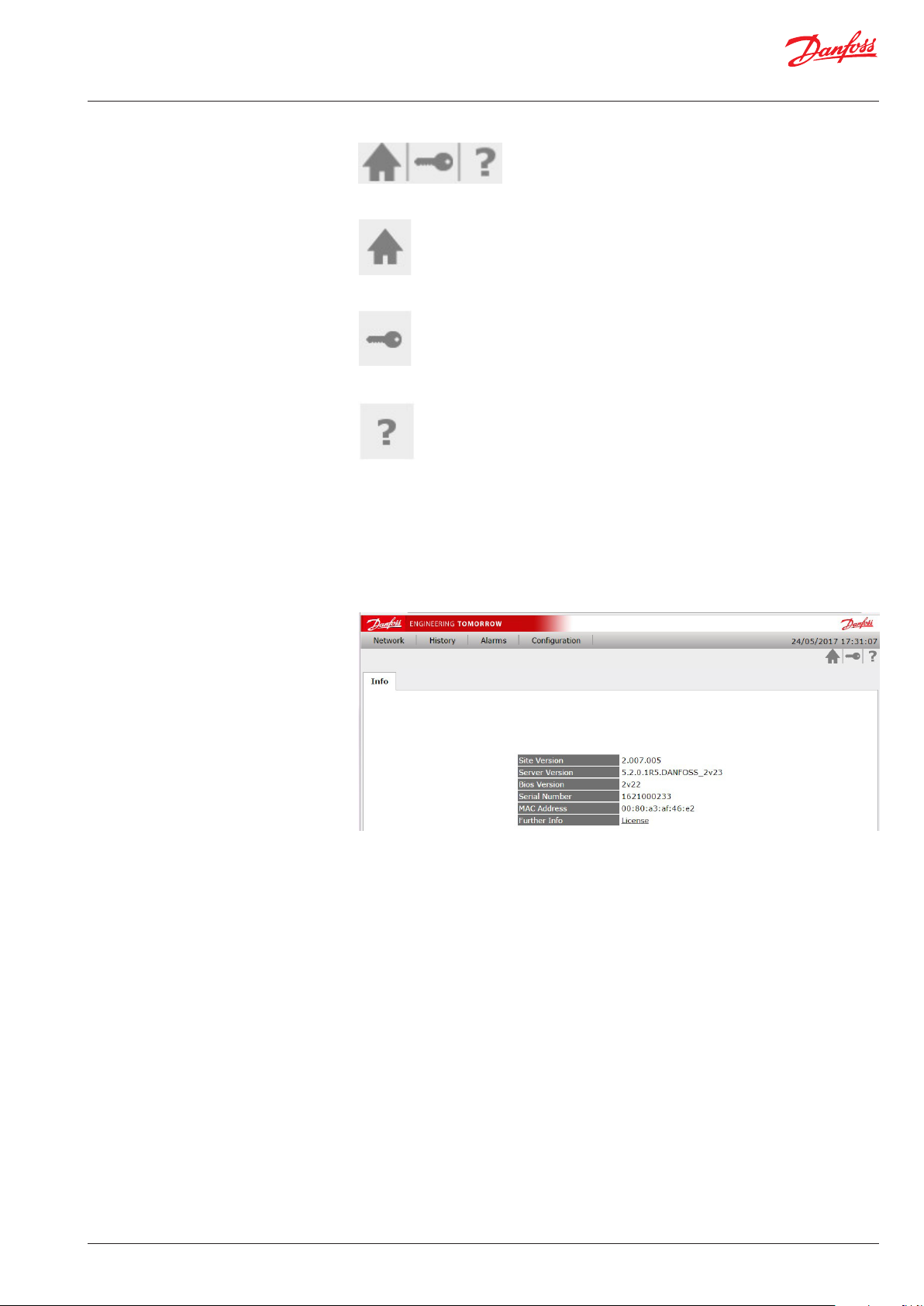
5.2 Main Buttons
The main buttons can be found at the top right of all the MCXWeb pages after login.
They are used for:
Back to home page (Network Overview)
Back to login page
Site information:
Version of the MCXWeb software interface
Version of the Web Server firmware in the MCX061V – MCX152V
Version of MCX061V-MCX152V BIOS
Serial number of the MCX061V – MCX152V
MAC address of the MCX061V – MCX152V
License information
© Danfoss | ADAP-KOOL® | 2017.07
DKRCC.PS.RI0.Z1.02 | 9
Page 10

User Guide | MCXWeb
5.3 Network Overview (home page)
The Network overview is used to list all the devices connected in the CANbus Network to
the MCX061V-MCX152V.
For each MCX device detected on the network, the following information is displayed:
• “Device Name” is the name defined in Configuration > Network
• “Node ID” is the CANbus address defined in the BIOS of the MCX device
• “Active” displays the device status:
A green dot means that the device is active (configured and connected)
A yellow dot means that the device is not configured: the template (tem) file has not
been associated with this device (see Paragraph 5.6.1, Configuration Network).
A grey dot means that the device is inactive and not connected.
If you click the line with the device you are interested in, you will enter the device
specific pages. If the device is active, you will see the pages populated with live values
(see Paragraph 5.7, Device Pages).
5.4 History
On this page you can graph historic data.
Select the variables you want to display as a graph, the date and period and then select Draw.
You can use the mouse wheel to zoom in and out of the graph and the arrows on the
bottom right corner to move the graph’s time period back and forward.
The graph may also display events (yellow flags); use the mouse to click a flag to view
additional information on the relevant event.
Press Export to export history data in CSV format.
© Danfoss | ADAP-KOOL® | 2017.07 10 | DKRCC.PS.RI0.Z1.02 |
Page 11

User Guide | MCXWeb
5.5 Alarms
5.6 Configuration
This page displays the list of the alarms active in all the devices connected to the
CANbus network.
The Configuration menu is used to configure items under the following headers: Network,
Template, Users, System, History.
Is also used to update the software (application) and firmware (BIOS) of the devices.
The configuration menu is visible only to users with service or admin access levels.
© Danfoss | ADAP-KOOL® | 2017.07
DKRCC.PS.RI0.Z1.02 | 11
Page 12

User Guide | MCXWeb
5.6.1 Configuration Network
This page shows which devices are connected in the CANbus network. You can also
manually add new devices by pressing the Add button and setting the ID (CANbus
address) of the device to be added.
For each device in the list you must specify the description (free text) and the
application template.
The application template is a file with a tem extension containing the description of
variables and parameters of the software application running in the MCX device.
Templates must be 1) created, 2) loaded and 3) associated
The template is associated to the device through the combo menu in the
Application column.
This combo menu is populated with all the tem files created with MCXShape and
transferred into the MCX061V-MCX152V following the instruction in the next paragraph.
Use the special entry “HIDDEN NODE” if you want to hide some nodes in the network
overview or if they do not have a template. This is typically used for nodes such as User
Interfaces (e.g. MMIGRS) or Accessories (e.g. MMIMYK)
Press Save to save the changes.
After the tem association, in the “Network Overview” page the device status changes from
Unconfigured to Active.
© Danfoss | ADAP-KOOL® | 2017.07 12 | DKRCC.PS.RI0.Z1.02 |
Page 13
User Guide | MCXWeb
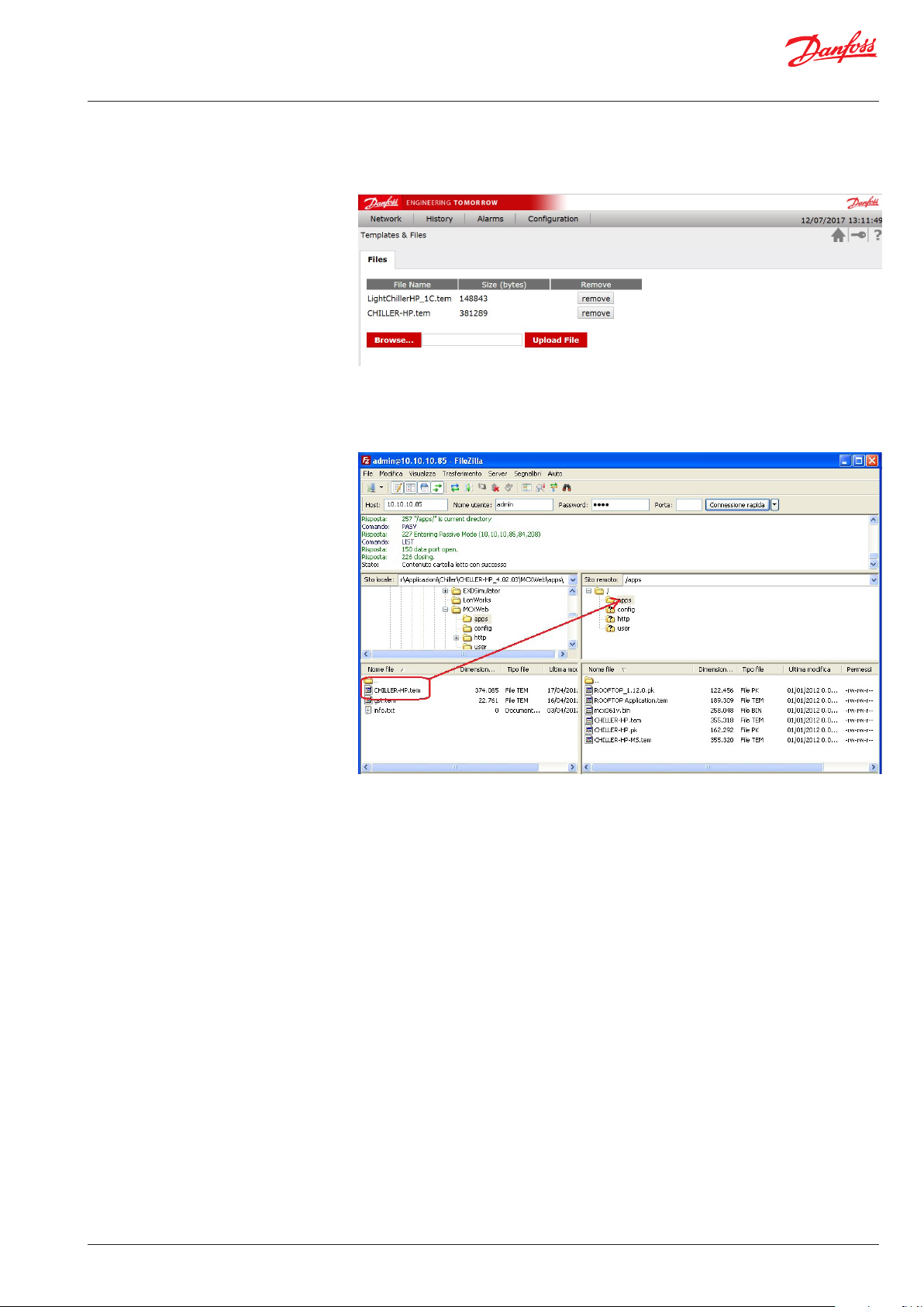
5.6.2 Configuration Template & Files This page is used to load the templates of the software applications running on the
MCX061V-MCX152V and other MCX connected to it into the MCX061V-MCX152V.
See the next paragraph for how to create a template.
The templates are loaded in the “apps” folder in the MCX.
You can also load them here via FTP:
Then the template must be associated to the MCX where the application software
described by that template is running (see the previous paragraph).
© Danfoss | ADAP-KOOL® | 2017.07
DKRCC.PS.RI0.Z1.02 | 13
Page 14

User Guide | MCXWeb
5.6.2.1 Create the application template with MCXShape
Before creating the template, use MCXShape to configure the MCX software application
according to your needs.
Then enable the generation of the template file from MCXShape. Go into the Tools-Gateway Configuration menu in MCXShape and select the “Enable Saving Web File” check box.
The template file of the MCX software application has the tem extension and it is created
during the “Generate and Compile” procedure.
The tem file is saved in the folder “MCXWeb\apps\” in the root of the software application.
© Danfoss | ADAP-KOOL® | 2017.07 14 | DKRCC.PS.RI0.Z1.02 |
Page 15

User Guide | MCXWeb
5.6.3 Configuration Users This lists all the users that can access to the MCXWeb interface. There are four possible
levels of access: guest, maintenance, service and admin. These levels correspond to the
levels assigned in the device template by the MCXShape tool.
Note that you can see only the users with the level equal or lower than the one you
logged in.
Select the "Mail Alarm" and "Mail Warning" check boxes to send notification emails to
the specified addresses when alarms and warnings occurs in any device present in the
CANbus network.
The destination email address is set in the Email column. See Paragraph 5.6.4.3, Site,
on how to set the SMTP mail server.
5.6.4 Configuration System
5.6.4.1 Network This page is used to configure the MCXweb inside the local network to which it belongs.
You can manually assign a static IP address (DHCP disabled) or a dynamic address via the
dynamic host configuration protocol.
If DHCP is enabled, the IP address of the MCXweb device will be automatically assigned
by the DHCP server.
If the DHCP is not enabled, the network setting (IP Default Gateway, Primary DNS and
Secondary DNS) must be manually configured
You can also set the HTTP port.
© Danfoss | ADAP-KOOL® | 2017.07
DKRCC.PS.RI0.Z1.02 | 15
Page 16

User Guide | MCXWeb
5.6.4.2 NTP Configure the NTP (network time protocol)
Set the NTP server you wish to syncronize with. The MCX061V or MCX152V real time
clock will then be synchronized and set according to the defined timezone and daylight
saving time.
Daylight Saving Time:
- OFF: deactivated
- ON: activated
- EU: Start=2nd Sunday of March – End=1st Sunday of November
- US: Start=Last Sunday of March – End=Last Sunday of October
WARNING. The time synchronization of the MCX connected via CANbus to the MCXWeb is
not automatic and must be performed by the application software.
5.6.4.3 Site Set the Site Configuration used when users are notified of alarms and warnings by email. The destination email address is specified when configuring the Users.
Site Name is name of the site used in the alarm email message.
Email Domain is the name of the simple mail transfer protocol (SMTP) server that you
want to use.
Email Address is the email address of the sender.
For the Email Port and Mode, refer to the configuration of the SMPT Server.
Unauthenticated and SSL or TLS connections are managed. For each mode,
the usual port is automatically proposed but you can manually change it afterwards.
Example of email sent by MCXWeb:
© Danfoss | ADAP-KOOL® | 2017.07 16 | DKRCC.PS.RI0.Z1.02 |
Page 17

User Guide | MCXWeb
The Test Email Address is the address to which an email can be sent to test your settings.
In the event of a problem you will receive one of the following error codes:
ERROR
CODE
50 MAIL_FAIL_LOADING_CA_ROOT_CERTIFICATE Contact Danfoss Product Support
51 MAIL_FAIL_LOADING_CLIENT_CERTIFICATE Contact Danfoss Product Support
52 MAIL_FAIL_PARSING_KEY Contact Danfoss Product Support
53 MAIL_FAIL_CONNECTING_SERVER There is no connection with the mail
54 MAIL_FAIL_SSL_CONFIG_DEFAULT Contact Danfoss Product Support
55 MAIL_FAIL_SSL_CONF_OWN_CERT Contact Danfoss Product Support
56 MAIL_FAIL_SSL_SETUP Contact Danfoss Product Support
57 MAIL_FAIL_SSL_SET_HOSTNAME Contact Danfoss Product Support
58 MAIL_FAIL_HANDSHAKE Contact Danfoss Product Support
59 MAIL_FAIL_GET_HEADER_FROM_SERVER Contact Danfoss Product Support
60 MAIL_FAIL_EHLO Contact Danfoss Product Support
61 MAIL_FAIL_START_TLS TLS mode is not supported by the
62 MAIL_FAIL_AUTHENTICATION Authentication failed.
63 MAIL_FAIL_WRITING Authentication was successful, but
DESCRIPTION ACTION
server.
Check the Email Domain and
Email Port settings.
Also check Network Settings and the
physical connection
mail server.
Check the Email Mode setting.
Check the Email Address and Email
Password settings
something went wrong later. Retry.
If the problem persists, contact Danfoss
Product Support
5.6.4.4 Reboot Pressing the reboot button restarts the system. This button is normally used after applications (software) and BIOS (firmware) update.
© Danfoss | ADAP-KOOL® | 2017.07
DKRCC.PS.RI0.Z1.02 | 17
Page 18

User Guide | MCXWeb
5.6.5 Configuration Update
5.6.5.1 Application Update Copy the software application file, created with the MCXShape with the pk extension, into
The page is used to upgrade applications (software) and BIOS (firmware)
The application is the file produced by the MCXShape tool with the pk extension; it is
executed by the MCX and contains the control strategy and the user interface.
The BIOS is the firmware pre-installed in the MCX control, so it is the first code run at
power on.
To proceed with the application and BIOS update, follow these steps:
the MCX061V/MCX152V in one of these two ways (used in alternative):
1) From the Configuration->Template & Files menu select the application file and upload
it
2) Establish the FTP connection with the MCX Web Server as described in paragraph 3
MCXWeb connection. Copy the application file into the folder “apps”
After the file upload, press F5 to refresh the web pages.
From the Configuration->Update page, select the Application tab and click with the
mouse on the line of the device you want to update.
Select from the combo menu which is showing all the pk files that you have loaded, the
application to download into the device.
Confirm the update by pressing the Update button.
5.6.5.2 BIOS Update Copy the BIOS file with the bin extension into the MCX061V/MCX152V in one of these two ways (used in alternative):
1) From the Configuration->Template & Files menu select the BIOS file and upload it
2) Establish the FTP connection with the MCX Web Server as described in paragraph 3
MCXWeb connection. Copy the BIOS file into the folder “apps”
After the file upload, press F5 to refresh the web pages.
Select the BIOS tab from the Configuration > Update menu and click the line of the device
you want to update.
Select the BIOS to be downloaded into the device from the combo menu.
Confirm the update by pressing the Update button.
If there is the appropriated BIOS (bin file) for the MCX model selected in the MCXWeb
server app folder, the BIOS update procedure is started, otherwise the “File not found”
message will be displayed.
© Danfoss | ADAP-KOOL® | 2017.07 18 | DKRCC.PS.RI0.Z1.02 |
Page 19

User Guide | MCXWeb
5.6.6 Configuration History
Define the variables to be shown in a graph (max 32) in the History pages.
You must define:
• Node to which the variable belongs.
WARNING. It is possible to plot a graph of data only from the MCX061V or MCX152V
where the web server is running, therefore you must select only this node.
• Parameter: variable to view in the History page. All the variables defined in the application software are listed but only the variables saved by application software must be
selected. Please refer to the documentation of the specific application software.
• Color: defines the line color (hex code) in the graph in the History page.
• File: defines the file from which the variable value is taken, whether it is stored in the
internal memory (0:/) or external memory card (1:/). Please refer to the documentation
of the specific application software.
• Position: the position (column) of the variable in the file. Please refer to the documentation of the specific application software.
Example of software developed with MCXDesign:
© Danfoss | ADAP-KOOL® | 2017.07
DKRCC.PS.RI0.Z1.02 | 19
Page 20

User Guide | MCXWeb
5.7 Device Pages
5.7.1 Device Overview The overview page is typically used to show the main application data.
From the home page, if you click on a specific device you will enter the
device-specific pages.
The default page is empty.
By pressing the Manage button you can select the main parameters to display in this page.
When you have selected all the variables you need, press Save and you will see them on
the Overview page
© Danfoss | ADAP-KOOL® | 2017.07 20 | DKRCC.PS.RI0.Z1.02 |
Page 21

User Guide | MCXWeb
5.7.1.1 Customization of the Overview Page
This page can be customized with images and command buttons, by defining the HTML
page to be used as interface.
The customized HTML page is placed in the /http folder of the MCX061V-MCX152V server.
The name is DeviceOverview_applicationname.html where applicationname is the name
of the application defined in the MCXShape tool.
© Danfoss | ADAP-KOOL® | 2017.07
DKRCC.PS.RI0.Z1.02 | 21
Page 22

User Guide | MCXWeb
5.7.2 Device Details This page gives you access to the different parameters and variable values by navigating the menu tree.
When the parameters are displayed, you can check the current value, the unit of
measurement and the minimum and maximum values for each of them.
To change the current value of the parameter, click on it.
© Danfoss | ADAP-KOOL® | 2017.07 22 | DKRCC.PS.RI0.Z1.02 |
Page 23

User Guide | MCXWeb
5.7.3 Device Alarms This page displays all the alarms active in the device.
5.7.4 Device Graphs This page lets you select the variables to populate the real-time graph.
Press “Change Selected”, navigate the menu tree and select the variable you want to
display in a graph.
The period to display in the graph window can be configured in the range of 1 to
24 hours.
Once variables and period have been selected, press the Draw button to start plotting the
graph using the real-time variables value.
© Danfoss | ADAP-KOOL® | 2017.07
DKRCC.PS.RI0.Z1.02 | 23
Page 24

User Guide | MCXWeb
5.7.5 Device Backup This page is used to save the current value of the parameters. It allows you to make a
backup of your configuration and to replicate the same configuration in a different device
where the same software application is running.
The parameters selected in this page (all by default) will be saved into the file specified in
a dialog box.
5.7.6 Device Restore
By default, the file name is ID_Applicationname.bak, where ID is the address in the CANbus
network and Applicationname is the name of the application running in the device.
The backup file is saved in the /user folder in the MCX061V-MCX152V server.
This page contains all the backup files in the \user folder in the MCX061V-MCX152V
server.
Only the backup file created with the same application running in the current device will
be accepted upon restoring.
To start the restore process of the saved parameters, click the selected backup file.
If you select a backup file that is not compatible with the application running in the current
device, you will stay in the previous page. Otherwise the following page will appear
© Danfoss | ADAP-KOOL® | 2017.07 24 | DKRCC.PS.RI0.Z1.02 |
Page 25

User Guide | MCXWeb
Then deselect the parameters you do not want to restore and press “Restore configuration”
to start the process. A pop up window will show you the progress and finally a status report.
5.7.7 Device Info This page displays the following information relating to the current device: Application name and version BIOS version Serial number of the hardware
© Danfoss | ADAP-KOOL® | 2017.07
DKRCC.PS.RI0.Z1.02 | 25
Page 26

User Guide | MCXWeb
6. MCXWeb Simulator
You can simulate the web interface of MCX061V-MCX152V with the Simulator in your
MCXShape-based software application in the following way:
• Ensure you have the latest MCXWeb folder in the root of your application software:
• Enable the generation of the template file from MCXShape. Go into the Tools-Gateway
Configuration menu in MCXShape and select the “Enable Saving Web File” check box.
• Generate and compile
• Run the Simulator and press the Configuration button: enable the MCXWeb simulation
if not done already.
© Danfoss | ADAP-KOOL® | 2017.07 26 | DKRCC.PS.RI0.Z1.02 |
Page 27

User Guide | MCXWeb
• A Web button will be displayed in the MCXSimulator to start the MCXWeb simulation.
• Press the Web button and the MCXWeb login page will be opened in your default web
browser. Insert login (admin) and password (PASS) and you are ready to start. Pages will
be populated with data from the simulator.
© Danfoss | ADAP-KOOL® | 2017.07
DKRCC.PS.RI0.Z1.02 | 27
Page 28

User Guide | MCXWeb
7. 7 Appendix Application template
XML structure
File name: /app/application_template_name.xml
XML structure:
<?xml version="1.0" encoding="UTF-8"?>
<Template>
<VarInfo>
<AppName></AppName>
<AppDescr></AppDescr>
<AppCode></AppCode>
<AppID></AppID>
<AppVer></AppVer>
<TemplateVer></TemplateVer>
</VarInfo>
<VarList>
<Var>
<VarCat></VarCat>
<VarName></VarName>
<VarAddr></VarAddr>
<VarType></VarType>
<VarLabel></VarLabel>
<VarDescr></VarDescr>
<VarBitMask></VarBitMask>
<VarShift></VarShift>
<VarScale></VarScale>
<VarOffset></VarOffset>
<VarDecimal></VarDecimal>
<VarMax></VarMax>
<VarMin></VarMin>
<VarDefault></VarDefault>
<VarAccess></VarAccess>
<VarRW></VarRW>
<VarVisibility></VarVisibility>
<VarConstant></VarConstant>
<VarEnumList><VarEnum>
</VarEnum></VarEnumList>
<VarGroupList>
<VarGroup></VarGroup>
</VarGroupList>
<VarAlarmGroup></VarAlarmGroup>
</Var>
….
</VarList>
<Template>
* <Var></Var> tag MUST be written in a single row with “\r\n” terminator.
© Danfoss | ADAP-KOOL® | 2017.07 28 | DKRCC.PS.RI0.Z1.02 |
Page 29

User Guide | MCXWeb
Var tag structure:
Tag Description Notes
VarCat Var category 0 undefined
1 parameter
2 DI /DO
3 alarms
4 status var
VarName Var identification
VarAddr Modbus address Decimal representation
VarType Var type s16
u16
s32
u32
VarLabel Var label
VarDescr Var description Max 60 chars
VarBitMask Bitmark filter ( used for packed
alarms )
VarShift Number of right shift to applied
after VarBitMask's filter.
VarScale Scale to be applied to the value
returned from read var request
VarOffset Offset to be applied to the value
returned from read var request
VarDecimal Number of decimals to be applied
to the value returned from read
var request
VarMax Maximum value
VarMin Minimum value
VarDefault Default value
VarRW Read Only / Read-Write 0 read only
VarVisibility Is visible 0 hidde
VarConstant Is constant 0 editable
VarEnumList List of VarEnum tag VarEnum tags represents the list
VarGroupList List of VarGroup tag VarGroup tag sequence rep-
VarAlarmGroup
Alarms group Identifier of alarms group.
32 bits bitmask
1 read write
1 visible
1 constant
of descriptions to be applied to
the value returned from read var
request.
resents the tree structure of
groups.
The value is considered as bitmask of 32 alarms.
© Danfoss | ADAP-KOOL® | 2017.07
DKRCC.PS.RI0.Z1.02 | 29
Page 30

© Danfoss | ADAP-KOOL® | 2017.07
DKRCC.PS.RI0.Z1.02 | MCXWeb| 30
 Loading...