

Page 1

User manual
MCXShape -
The easiest way to get control
of your HVAC/R system
One software to configure and optimize any HVAC/R application
www.danfoss.com/mcx
Page 2

User manual | MCXShape standard software
Index
1.0 General overview 4
2.0 Installation 5
3.0 File menu 6
4.0 View menu 10
5.0 Tools menu 11
5.1 Launch MyK Manager 11
5.2 Edit languages (advanded) 11
5.3 Import language file… 12
5.4 Export language file… 12
5.5 Export menu structure 13
5.6 Project Options 13
5.7 Gateway Configuration 14
5.8 Edit EDF settings 15
5.9 Edit measurements units 16
5.10 Edit VR function (advanced) 16
5.11 Edit I/O types (advanced) 16
6.0 Application data 17
7.0 Tabs description 18
7.1 Compile & Upload 18
7.2 Menu & Parameters 19
7.3 Alarms: 27
7.4 Digital input 29
7.5 Analog input 30
7.6 Digital output 31
7.7 Analogue output 32
7.8 Application strings 33
7.9 Functionalities 33
7.10 Enum 33
8.0 EDF file generation for connection with SC355/SM850 34
8.1 Tools Menu 34
8.2 Edit XML Tags 36
8.3 Edit EDF menu 37
8.4 Find in the EDF menu 38
8.5 Edit parameter properties in EDF menu 38
8.6 Menu & Parameters tab 39
8.7 EDF generation 39
9.0 CDF file generation 39
7.2.1 Menu & Parameters – Tree View 19
7.2.2 Menu & Parameters – Grid View 24
© Danfoss | DCS (ADAP-KOOL®) | 2019.01
DKRCC.PS.RJ0.E4.02 | 2
Page 3
User manual | MCXShape standard software
Table of new contents:
Manual
Version
V E2 V2.01
V E3 V3.06 All chapters have been changed for consistency with
E4 This
version
MCXShape
Software
Version
V4.01 All chapters have been changed for consistency with
New Contents
MCXShape v3.0x.
MCXShape v4.0x Updated the EDF generation
© Danfoss | DCS (ADAP-KOOL®) | 2019.01
DKRCC.PS.RJ0.E4.02| | 3
Page 4

User manual | MCXShape standard software
1.0 General overview
MCXShape is the tool used to configure the software application for downloading in the MCX
programmable control.
You can use this configuration tool to define the model of MCX, the structure of the user interface
menu, the default values for each parameter, the alarms set and actions, the I/O configuration, the
interface languages and much more.
Moreover, by using MCXShape you can compile the software application, execute the Simulator
software and download the software application in the MCX controller via serial communication or
by copying it to the MyK memory (see MMIMYK Programming module – 080G0073).
Note that when MCXShape is used within the MCXDesign environment, some functionalities may be
hidden.
© Danfoss | DCS (ADAP-KOOL®) | 2019.01
DKRCC.PS.RJ0.E4.02 | 4
Page 5
User manual | MCXShape standard software
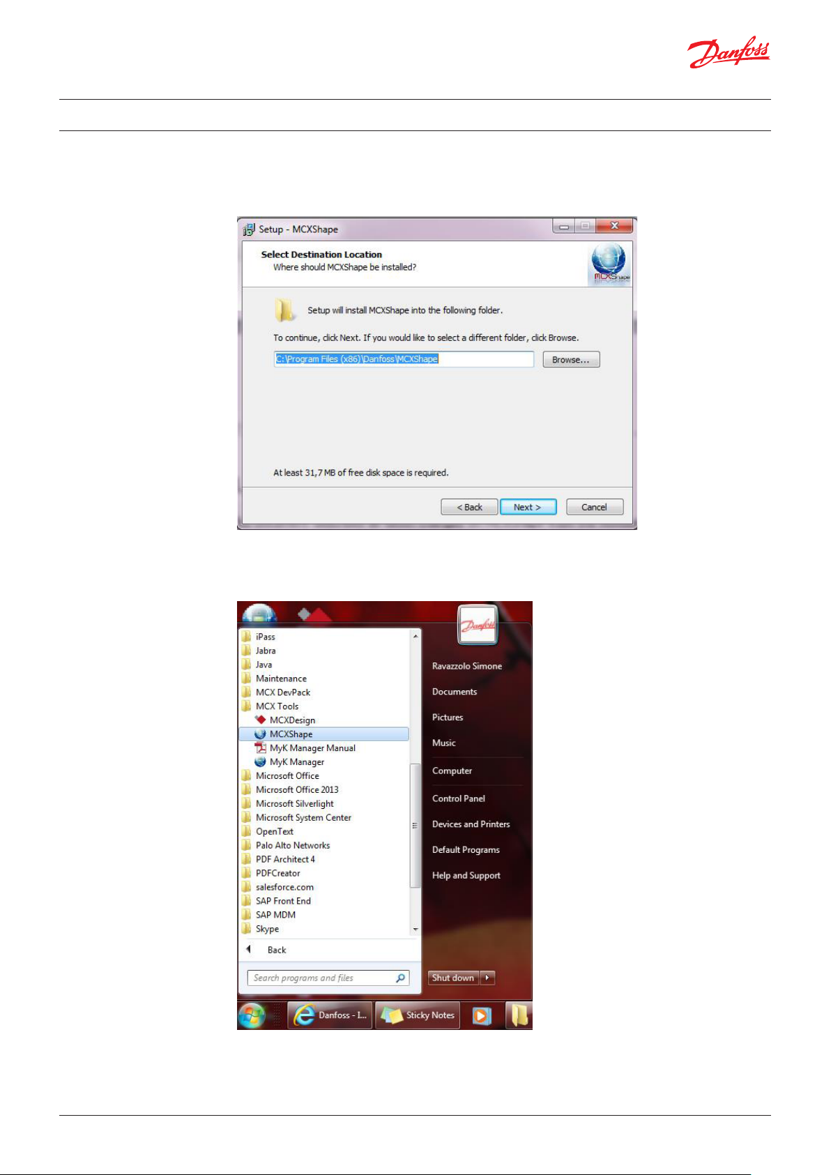
2.0 Installation
The name of the installation file is MCXShapeSetup.exe.
To install the program on your PC, execute the file, follow the installation instruction and select your
preferred options.
At the end of the installation you can run the tool using the icon on the desktop or from the program
menu.
© Danfoss | DCS (ADAP-KOOL®) | 2019.01
DKRCC.PS.RJ0.E4.02| | 5
Page 6
User manual | MCXShape standard software
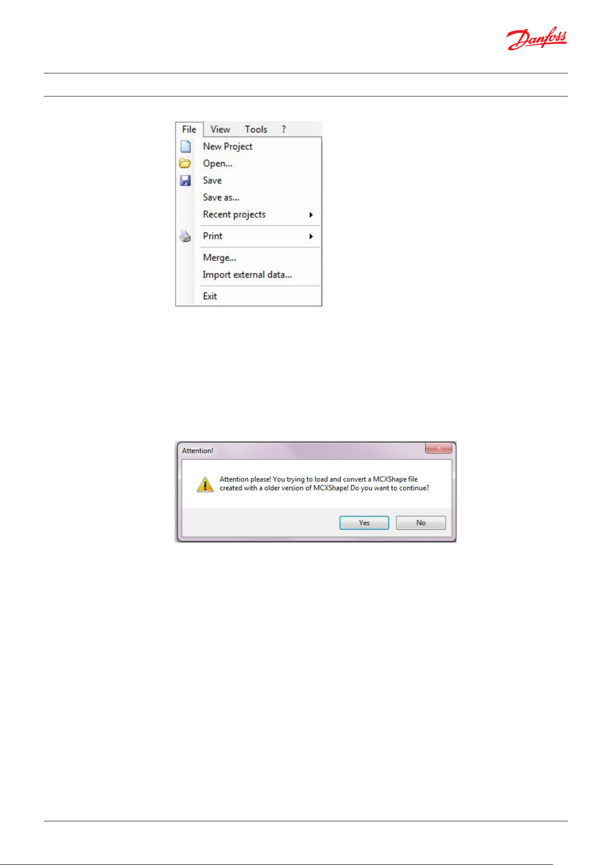
3.0 File menu
New Project (advanced):
to start a new empty project. Active only in combination with MCXDesign
Open:
the function to load the configuration file
The configuration file is located in the root of the software application. Its extension is MCXS.
NOTE:
If the .MCXS file that you are opening has been created with an older version of MCXShape, the
following panel will appear.
You can choose to convert this file to the new version 4.x of MCXShape or continue to work with the
previous version
Remember that you cannot use an old version of MCXShape to open a file already imported into the
new version.
If you do choose to convert the file to the new version, a backup file will be saved in the MCXShape
old version format.
Save:
to save the configuration in the original MCXS file
Save as:
to save the configuration in a new MCXS file
Recent projects:
to easily access recent projects
© Danfoss | DCS (ADAP-KOOL®) | 2019.01
DKRCC.PS.RJ0.E4.02 | 6
Page 7
User manual | MCXShape standard software
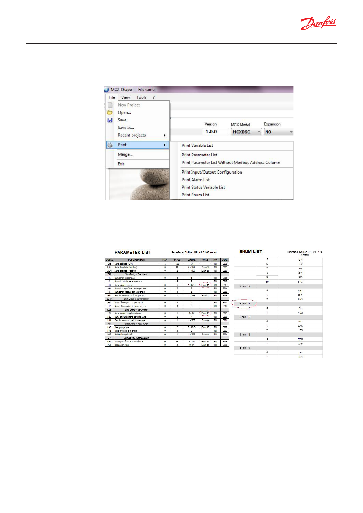
Print:
to print all of the project data (Variable List), the parameters with or without the Modbus address,
Input/Output configuration, alarms, status variables, enumerations (an enumeration is a string
associated with the value of a parameter, e.g. NO=0, YES=1)
Print Enum List:
For an explanation of the Enumeration elements listed in the UNIT column of a Print Report, you can
use the report generated by Print Enum List.
See, for example, E nu m 11 in the two images below where the first has been generated with the Print
Parameter List command.
© Danfoss | DCS (ADAP-KOOL®) | 2019.01
DKRCC.PS.RJ0.E4.02| | 7
Page 8
User manual | MCXShape standard software
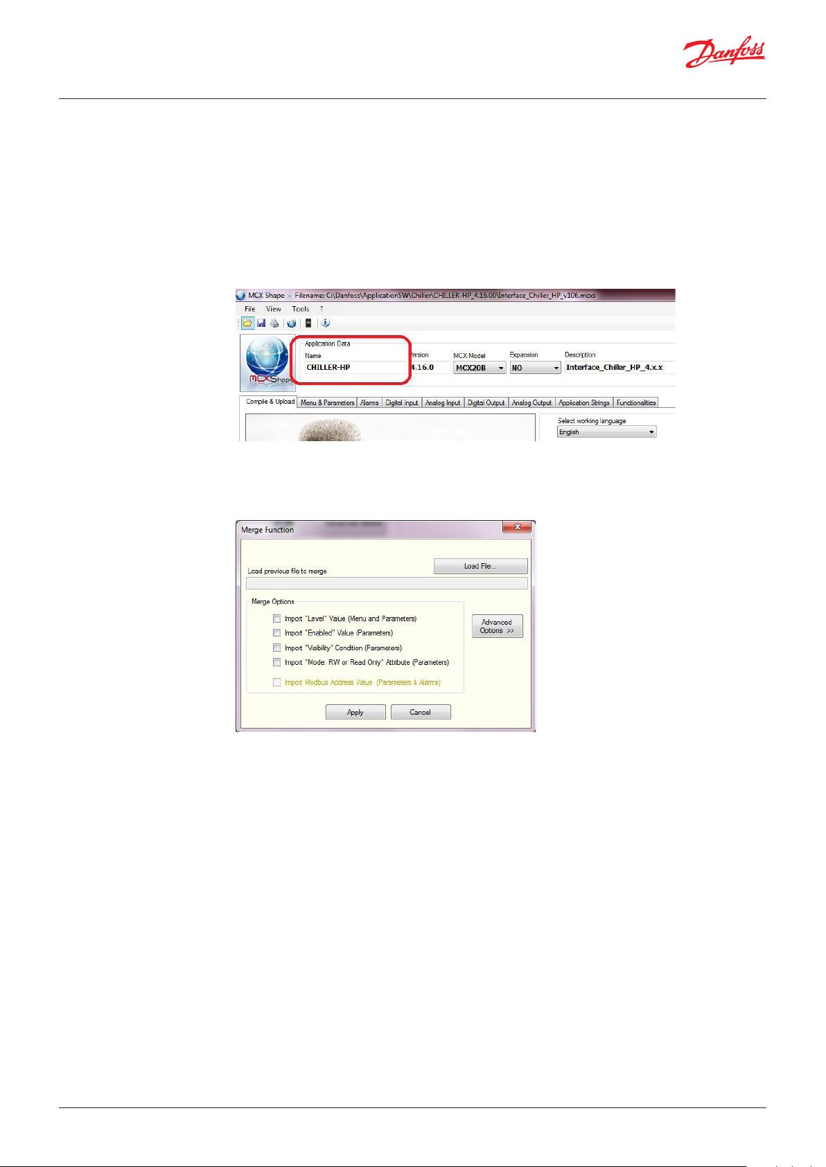
Merge:
The merge function is useful for importing a parameter configuration from an old MCXS file into a
new one.
The merge function is most commonly used to import a configuration already set for one application
into the configuration file of the newest version of the application.
The procedure for using the merge function is as follows:
• Open the new MCXS file.
• Verify the name filed in the application data: it must be the same for both new and old files.
• Select the merge function from the File menu and set the appropriate merge options as necessary.
Using the default basic options, the parameter values of the old file will overwrite the parameter
values of the new file. Usually this is all that you need to do. However, in the Merge Options you
can select other attributes for merging:
Level:
to import the access level for menus and parameters from the old file
Enabled:
to import the “enabled” attribute from the old file
Visibility:
to import the visibility conditions from the old file
RW or Read Only:
to import the R/W attribute from the old file
Modbus Address (in development):
to import the Modbus addresses from the old file and maintain compatibility with other devices
which refer to these addresses.
© Danfoss | DCS (ADAP-KOOL®) | 2019.01
DKRCC.PS.RJ0.E4.02 | 8
Page 9

User manual | MCXShape standard software
The descriptions of the parameters remain the same in the new file unless one of the advanced
options is selected. These can be used to import the following from the old file: the menu dictionary,
the parameters dictionary, the alarms dictionary, the strings dictionary and the I/O dictionary.
NOTE: Select these options only if you want to overwrite the descriptions in the new file with the
descriptions from the old file (not recommended).
• Click on the “Load File…” button to select the old file and then click on the Apply button.:
Import external data … (advanced)
Reserved
© Danfoss | DCS (ADAP-KOOL®) | 2019.01
DKRCC.PS.RJ0.E4.02| | 9
Page 10
User manual | MCXShape standard software
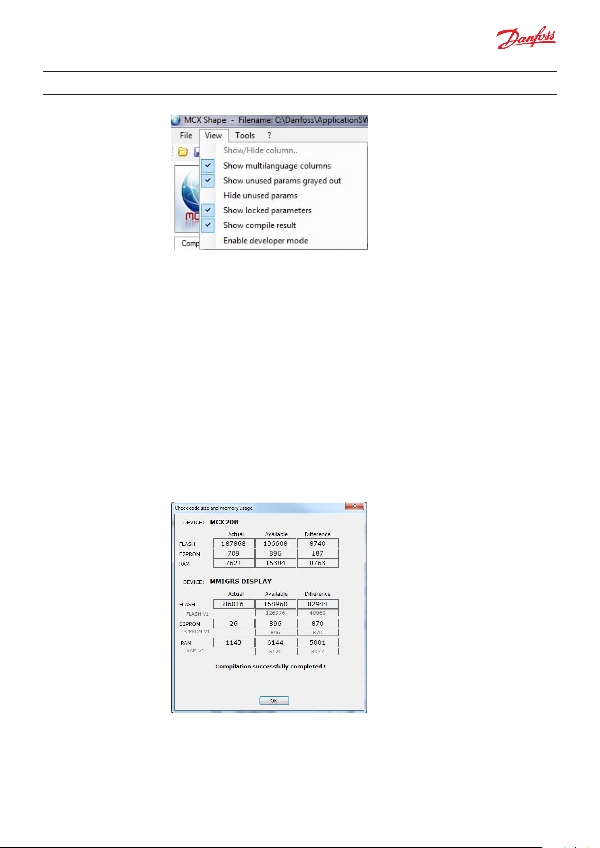
4.0 View menu
The View menu is useful for customising the way data appears in MCXShape.
Show/Hide column..:
to select a column to display. This is enabled only when the Menu & Parameters tab is selected
Show multilanguage columns:
to enable/disable the visualisation of the multilanguage columns on the right side of the workbench
Show unused params grayed out:
to grey out parameters not used and simplify the visualisation. Parameters are not used when their
visibility condition are not true or when the related functionality is not enabled.
Hide unused params:
to hide parameters not used and simplify the visualisation. Parameters are not used when their
visibility condition is not true or when the related functionality is not enabled.
Show locked parameters:
to highlight special parameters
Show compile result:
to show the report at the end of the compiling process. In this report you can find the used and
available value for each type of memory.
Enable developer mode: to enable the viusalization of advanced menu for developers (hereafter
“advanced”).
Close MCXShape to get back to normal mode.
© Danfoss | DCS (ADAP-KOOL®) | 2019.01
DKRCC.PS.RJ0.E4.02 | 10
Page 11
User manual | MCXShape standard software
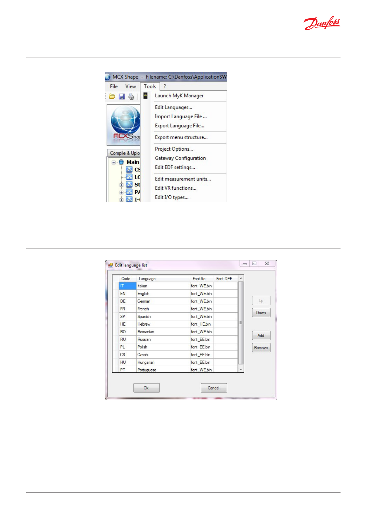
5.0 Tools menu
5.1 Launch MyK Manager
Launch MyK Manager to start the MyK Manager tool (see the MyKManager Manual).
5.2 Edit languages (advanded)
This is used to manage project languages. Here you can define the font for each language (advanced),
change the order of the languages using the Up and Down buttons and add a new language or
remove an existing one.
The available font files are in your project’s bin folder; for each font there are a couple of files with BIN
and DEF extensions. The structure of the font file name is font_XX, where XX = WE for Western
Europe, EE for Eastern Europe, RU for Russia etc.
For each language you must specify the name of the .BIN font file to be used. A .DEF file name can be
omitted if equal to .BIN.
© Danfoss | DCS (ADAP-KOOL®) | 2019.01
DKRCC.PS.RJ0.E4.02| | 11
Page 12
User manual | MCXShape standard software
5.3 Import language file…
This is used to import the application vocabulary from the special Excel file used for the translation.
The Excel file will have been created previously by the Export language file option.
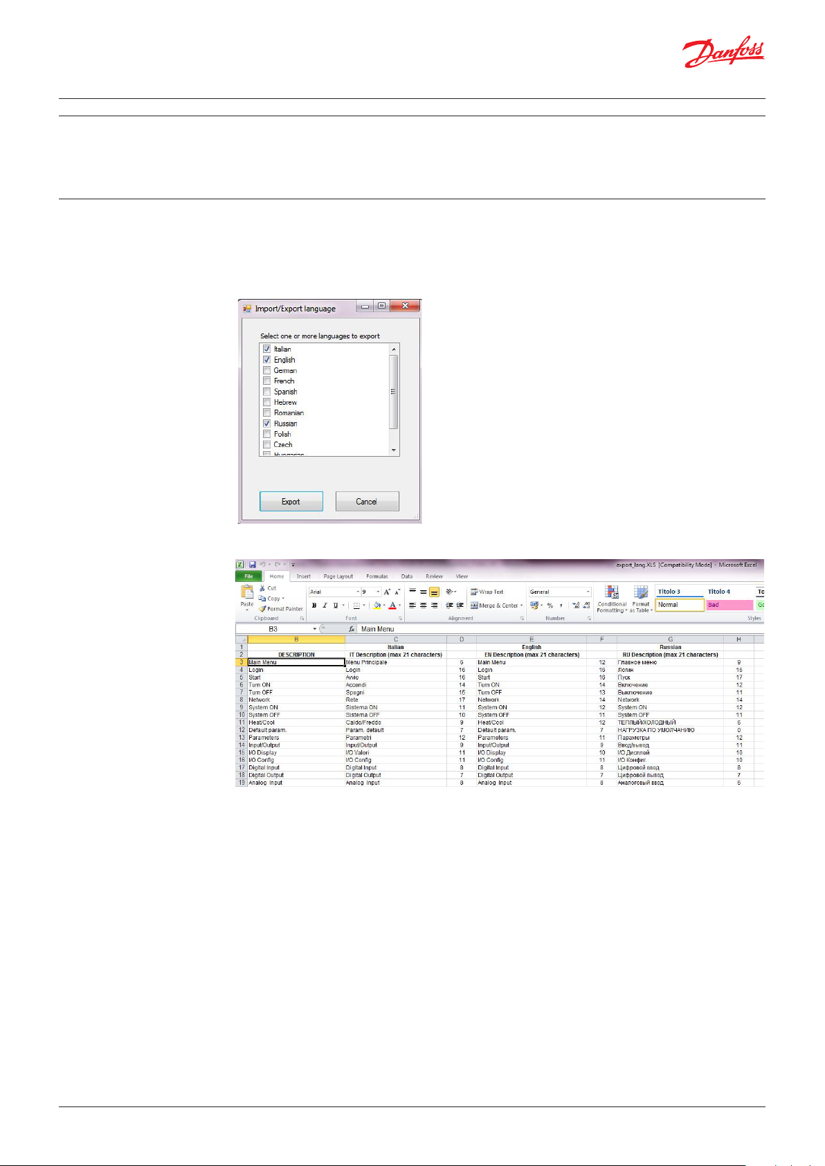
5.4 Export language file…
This is used to export all the application vocabulary of the selected languages in an Excel file. This
option is used to facilitate the translation of all the strings present in the user interface of the
application.
A pop-up window allows you to select the language you want to export:
Here is an example of the .XLS file that is generated:
To the right of each language you can find a number representing the number of characters still
available before reaching the maximum number generally allowed by standard applications. This is
only a guide, as the effective number is defined by the application and may change accordingly. The
number is typically 21 characters (1 line on the MMIGRS2 user interface) for menus and 42 characters
(2 lines) for parameters and alarms.
© Danfoss | DCS (ADAP-KOOL®) | 2019.01
DKRCC.PS.RJ0.E4.02 | 12
Page 13

User manual | MCXShape standard software
5.5 Export menu structure
This is used to save all menu items and parameters in Excel format.
5.6 Project Options
This is used when you save application files to the MyK accessory, as well as for some advanced
options.
MyK Files Settings
In the “MyK Files Settings” section you can select:
• the disk to copy files to: disk 0 (MyK internal memory) or disk 1 (memory card)
• the name of the destination folder within the Myk file system
© Danfoss | DCS (ADAP-KOOL®) | 2019.01
DKRCC.PS.RJ0.E4.02| | 13
Page 14

User manual | MCXShape standard software
Compile options:
This is used to set the name of the batch file executed when the Generate & Compile button on the
Compile & Upload tab is pressed.
Advanced Options
• Enable Modbus Address Editable for Parameters: Modbus addresses of Parameters and Status
Variables can be edited and/or kept unchanged between different application releases.
In order to enable this functionality, you must tick the “Enable Modbus Address Editable for
Parameters” check box which is not ticked by default.
• Lock I/O config in user mode: reserved
• Deny multiple virtual I/O assignment: reserved
5.7 Gateway Configuration
• Max label length set the maximum length of the labels, to give you a warning if you enter more
characters than expected
• AGF UI Menu allow you to select which menu will be exported to the AGF files
This tool is used to create the configuration file and application for external gateways that
communicate with external parts – for example, building management systems or remote
supervisors.
Files are created in individual folders within your project when you press the Generate & Compile
button.
The Netbiter Settings create within the NetBiter folder an .xml file for the configuration of the
Netbiter remote control gateway.
The BACnet Settings create within the BACnet folder the CVS files for configuring the gateway used
to communicate with external parts via the BACnet protocol.
© Danfoss | DCS (ADAP-KOOL®) | 2019.01
DKRCC.PS.RJ0.E4.02 | 14
Page 15

User manual | MCXShape standard software
Enable the EDE file to generate standard EDE files.
The serial number (device instance number) can be calculated from the MAC address of the gateway
by pressing the following button:
If more than one MCX unit must be connected to the network, tick “Enable Multi-Unit” and insert the
node ID of each unit, separated by semicolons.
The LonWorks Settings create within the LonWorks folder the CVS file for configuring the gateway
used to communicate with external parts via LonWorks protocol.
If more than one MCX unit must be connected to the network, tick “Enable Multi-Unit” and insert the
node ID of each unit, separated by semicolons.
5.8 Edit EDF settings
The EWON Settings create within the eWon folder the .txt file for configuring the eWon remote
control gateways (not supplied by Danfoss).
The CAN-RS485 Gateway creates within the Can-485 folder the application that must be
downloaded into the MCX used as a gateway (typically MCX06D is used), should you want to have at
your disposal an additional RS485 serial port for communicating with external parts via Modbus.
NOTE. This is not anymore needed if you load into the MCX the special application “Expansion and
Gateway Application SW”.
The MCX Web Template creates within the MCXWeb folder the template file to be used by MCX
models provided with an internal web server (e.g. MCX061V and MCX152V).
See chapter 8.0 EDF file generation for connection with SC355/SM850.
© Danfoss | DCS (ADAP-KOOL®) | 2019.01
DKRCC.PS.RJ0.E4.02| | 15
Page 16

User manual | MCXShape standard software
5.9 Edit measurements units
If you click on the menu item “Edit measurement units…”, an edit page will appear where you can
add or remove predefined measurement units.
Predefined measurement units are used when you create a new parameter.
5.10 Edit VR function (advanced) Reserved
5.11 Edit I/O types (advanced) To set the I/O types used in the I/O tabs.
© Danfoss | DCS (ADAP-KOOL®) | 2019.01
DKRCC.PS.RJ0.E4.02 | 16
Page 17

User manual | MCXShape standard software
6.0 Application data
This is where general information regarding the application is provided.
On the title there are the path and name of the configuration file.
Name
is a text field which specifies the name of the application. It is used as a control in the merge function
(see Merge).
Version
is a text field which specifies the version of the application.
MCX Model
is a combo box used to choose the model of MCX hardware that the application will be downloaded
to. When you choose the type of hardware, the MCXShape will guide you in choosing the I/O
configuration (e.g. number and types of I/O available).
Expansion
is used to select the model of the possible I/O expansion, if present.
NO means that no expansion is connected.
Yellow is the background colour of the additional I/O available in the expansion.
Description
is a text field which describes the application.
© Danfoss | DCS (ADAP-KOOL®) | 2019.01
DKRCC.PS.RJ0.E4.02| | 17
Page 18

User manual | MCXShape standard software
7.0 Tabs description
7.1 Compile & Upload
This is the first tab in the MCXShape workbench.
Select working language:
This allows you to select the default language to be used by the application and the language to be
used by MCXShape in the Description column of the other tabs.
Multilanguage (advanced):
If the Multilanguage box is ticked, it means that the application supports more than one language.
Languages can be selected directly in the user interface
Select one or more languages:
This is used to select which languages to download to the MCX.
Generate & Compile:
This button is used to generate the application code in the bin folder (and eventually the gateway
files in the root), based on current configuration settings. Once generated, the code is compiled to
create the app.pk application file in both the bin and MykFiles folders.
The files in the MykFiles folder represent the compiled software code to be downloaded into the
MCX.
Start PC Simulator:
This button is used to start the Simulator software, to test the debugger and get practice using the
application.
© Danfoss | DCS (ADAP-KOOL®) | 2019.01
DKRCC.PS.RJ0.E4.02 | 18
Page 19

User manual | MCXShape standard software
Upload Into Device:
This is used to upload the application to the MCX via serial communication. A USB to RS485 converter
is required (not provided by Danfoss).
Copy Application To MyK:
This is used to copy project files from the MykFiles folder to the MyK memory following the setting
defined in Tool/Project Options.
7.2 Menu & Parameters
7.2.1 Menu & Parameters – Tree View
In the left window of this tab, the user can define the menu and submenu structure and which menu
each parameter belongs to.
When you select a menu line in the Parameters section, the cursor automatically points to the
corresponding parameters in the right window.
With a right-click of the mouse over the Tree View area, a context menu will open, allowing you to
perform the following actions:
© Danfoss | DCS (ADAP-KOOL®) | 2019.01
DKRCC.PS.RJ0.E4.02| | 19
Page 20

User manual | MCXShape standard software
Find
Find an element in the grid. The Find function works for Label, Description and Variable name
(variable name only if the variable name column is selected when the search starts).
Add new menu, Add menu, Remove menu
Adding and removing menus and submenus is useful for changing the way parameters are grouped
and shown in the MCX user interface.
Once you have created a new menu with “Add new menu”, you can drag and drop a parameter into it.
“Add menu” is used to create a copy of an existing menu; parameters inside the menu will be cloned.
Edit menu
If you enter the Edit menu when a menu line is selected, you can change some properties of the
menu.
You can change the label (used in the LED display) and the description of the menu in all the available
languages.
Moreover, you can change the menu protection level from 0 up to 4.
At level 4 you can hide the menu. At level 0 the menu is always visible. Levels 1, 2 and 3 are associated
with a password defined in the parameters Params_Password1, Params_Password2 and Params_
Password3 respectively.
NOTE: The protection level is shown when you point the mouse at a menu title.
Out Code and Variable Name (automatically generated) are fields used by developers only.
Functionality is used to link a menu to a functionality and make it disappear when that functionality is
not enabled (see 7.9 Functionalities).
Visibility, in general, is used to specify a logical condition (visibility rule) which must be verified to show the
element in the MCX user interface and in the SM800Danfoss System Manager. In this case, the visibility rule
applied to a menu line has not any effect on the MCX user interface but only on the SM800 Danfoss System
Manager.
© Danfoss | DCS (ADAP-KOOL®) | 2019.01
DKRCC.PS.RJ0.E4.02 | 20
Page 21

User manual | MCXShape standard software
If you enter the Edit menu when a parameter is selected, you can change some properties of the
parameter, in the same way as you can do directly from the parameter grid. See chapter 7.2.2 Menu &
Parameters – Grid View.
Note that:
“Datalogging” in the Edit window corresponds to the “History” column in the parameter grid,
“Config lock” in the Edit windows is the opposite of “Writab. in ON” column in the grid. When “Config
lock” is checked, the parameter can be changed only when the unit is in OFF state.
Add New Parameter, Remove Parameter
You can also add/remove parameters. This is useful in Developer mode. But even if you are not a
developer, you can use the newly created parameters as limits or conditions for other parameters and
alarms.
Example 1:
- Add the new parameter TTT-Test, assuming only two values, NO and YES:
© Danfoss | DCS (ADAP-KOOL®) | 2019.01
DKRCC.PS.RJ0.E4.02| | 21
Page 22

User manual | MCXShape standard software
Add Parameter, Remove Parameter
You can also add/remove parameters. This is useful in Developer mode. But even if you are not a
developer, you can use the newly created parameters as limits or conditions for other parameters and
alarms.
Example:
- Add the new parameter TTT-Test, assuming only two values, NO and YES:
- Use the new parameter in the Visibility column of another existing parameter (e.g. L01 in the
next figure).
Now, by selecting TTT=YES or NO in the MCX user interface, the L01 parameter will be either visible or
invisible.
In the same way, you can add the label of a new parameter to the Min or Max column of an existing
parameter.
Example:
Now the range of the SC1 parameter is limited by the new SCL and SCH parameters.
Or you can add the label of a new parameter to any of the following columns in the Alarms tab.
In the example, the Reset type of A03 alarm is defined by setting the AFr parameter in the MCX user
interface.
© Danfoss | DCS (ADAP-KOOL®) | 2019.01
DKRCC.PS.RJ0.E4.02 | 22
Page 23

User manual | MCXShape standard software
Cut, Copy, Paste
You can copy a menu tree with the context menu Copy or Cut.
Then you can select a menu and paste the menu tree (including submenus and parameters) with the
context menu Paste.
You can also use the keyboard shortcuts CTRL+C, CTRL+X, CTRL+V.
You can copy menus from one project into another.
If a menu with the same variable name already exists, the content will be merged (new parameters
and submenus will be added).
If a parameter with the same name already exists, it will be added to the menu, but properties will not
be copied or updated.
If the parameter doesn’t exist, it will be created as new.
Moving a parameter or a menu
To move a parameter, drag and drop it over another menu. The parameter will be moved at the end of
the new menu. If you drop the parameter over an existing parameter in the same menu, the dropped
parameter will be placed before it.
You can move a parameter within its menu using the ALT-UP and ALT-DOWN arrows or using the
Move Up and Down commands.
Moving a menu
Moving a menu is the same process as moving a parameter.
Show EDF menu
See 8.0 EDF file generation for connection with SC355/SM850
© Danfoss | DCS (ADAP-KOOL®) | 2019.01
DKRCC.PS.RJ0.E4.02| | 23
Page 24

User manual | MCXShape standard software
7.2.2 Menu & Parameters – Grid View
In the window to the right of the Menu & Parameters tab, the user can define the following
information for each parameter:
Label and Description
of the parameters: In the LED display, only the Label is shown, whereas in the graphic display both the
Label and Description are shown.
Min and Max:
These are the minimum and maximum values permitted for these parameters. A parameter’s
permitted values will be in the range between the Min and Max values.
Value:
This is the default value for a parameter. It can be set as a number or it can be a value chosen in a
combo box (Enum). In the latter case, the elements of the combo box are defined in the Text Value
column, where the text shown in the user interface and the corresponding numeric value are
specified.
Unit:
This is the unit of measurement.
Decimals:
This refers to the number of digits after the dot (or comma). This number must be consistent with the
number set in the Value column. For example, if the value written in the Value column is 10.5, the
number of decimals must be 1.
Level:
This is the level of protection for a parameter. There are four levels. Level 0 has no password and is
accessible by all users. Level 4 is never visible.
The other three levels have an associated password. The password at Level 3 has maximum priority.
R/W Mode:
R/W (Read/Write) defines whether the parameter can be changed from the MCX user interface;
‘R’(Read) defines whether it can be shown only and not changed.
Enabled:
Only if this box is ticked is the parameter shown on the MCX user interface.
Writable in On:
If this box is ticked, the parameter value can be changed even if the unit is ON. Otherwise, it can only
be changed when the controller is switched OFF.
© Danfoss | DCS (ADAP-KOOL®) | 2019.01
DKRCC.PS.RJ0.E4.02 | 24
Page 25

User manual | MCXShape standard software
Visibility:
This field can be used to specify a logical condition which must be verified to show the parameter in
the MCX user interface. All logical operators and their combinations can be used. The most common
logical operators are:
- = or == equal to
- != or <> not equal to
- > greater than
- < lower than
- and or &&
- or / ||
Enumeration:
This defines the text elements of the combo box used in the Values column.
If you select an Enumeration field and click over it, a panel will open to help you manage the
enumerations.
When you close the panel, a dialogue box asks the user whether they want to apply the changes to all
parameters using the same enumeration.
If you select No, the change will be applied only to the enumeration of the current parameter.
Broadcast
(not used by all of the application’s software): This defines whether the parameters value must be
transmitted only to MCX that are directly connected to the programming tool (PC or MyK), or whether
it must be broadcast to all nodes present on the CANbus network. Broadcast the value = 1, Do not
broadcast the value = 0.
Notes:
This is a free-text field for adding a comments (reminder, legends, help etc.).
Modbus Address (ADU):
Modbus registers numbers = (address+1).
Status Var:
If this box is ticked, the element is not a parameter but a status variable.
Status variables are considered as parameters, with the difference being that parameters are saved in
EEPROM (persistent memory) and status variables are saved in RAM (volatile memory).
Status variables are available in the parameters table and in the menu tree. They are not visible in the
MCX user interface.
© Danfoss | DCS (ADAP-KOOL®) | 2019.01
DKRCC.PS.RJ0.E4.02| | 25
Page 26

User manual | MCXShape standard software
Typ e (advanced)
Data type of parameters and status variable: This is selectable by developers only for status variables.
Gateway:
A parameter or variable is exported to the external gateways (Lonworks, BACnet or Netbiter... ) only if
this box is ticked.
Functionality (advanced):
This defines which functionality a parameter or variable belongs to (see the Functionality tab).
Variable Name (advanced):
This is the name of the variable inside the code. This name must not be changed.
History (advanced):
A parameter or variable will be automatically logged by SC355/SM850 only if this box is ticked. If the
box is not ticked, it will not be logged automatically, but you can still select the variable to be logged.
If the box is grayed, the user will not be able to log the variable.
EDF r/o (advanced):
See chapter 8.0 EDF file generation for connection with SC355/SM850.
XML Tag (advanced):
See chapter 8.0 EDF file generation for connection with SC355/SM850.
EDF App Mode (advanced):
See chapter 8.0 EDF file generation for connection with SC355/SM850.
Copy Type: (advanced):
an application can use this property to define the way variables are managed by a backup/restore
functionality. “Copy” is used to identify the variables that must be saved and restored. “Clone” is used
to identify those variables that must be saved but can be excluded from restoring (e.g. useful for the
network settings, for not breaking an existing network communication after restoring).
Languages:
These are the columns where the user can translate the user interface into other languages. Every
column has a language name as its title (Italian, English etc.). When translating languages, it is
recommended that you do not work directly on the grid but use the export/import functions on the
Tools menu (5.0 Tools menu).
NOTE:
A context menu option is available by right-clicking over the grid.
© Danfoss | DCS (ADAP-KOOL®) | 2019.01
DKRCC.PS.RJ0.E4.02 | 26
Page 27

User manual | MCXShape standard software
This allows you to:
- Find an element in the grid. The Find function works for Label, Description and Variable name
(variable name only if the variable name column is selected when the search starts).
- Easily select or unselect all the parameters in the Gateway column.
- Regenerate Modbus addresses (advanced) prepared for future use.
- Copy all grid content to the clipboard (and eventually to paste it into an Excel file).
7.3 Alarms:
In the Alarms tab the user can define the alarms list, the conditions and the actions to be taken when
the alarm is active.
Code: This is the alarm code used in the LED user interface display.
Description: This is the alarm description used in the graphic user interface display.
Enable: 1 = alarm is enabled; 0 = alarm is disabled.
Reset: This is the type of reset for the alarm.
0 = manual. The reset must be done manually from the MCX user interface.
-1 = automatic. The reset is done automatically when the alarm conditions no longer exist.
>0 = semi-automatic, number of occurrences within the period. This means that the alarm is
automatically reset for the “Reset” number of attempts in the specified period of time, but if the alarm
occurs one more time, it becomes manual.
This column can be set to be equal to a parameter label, so it can be changed on field by the user.
Period: This is the period of time in which a semi-automatic alarm can occur and be reset a specific
number of times before becoming manual.
This column can be set to be equal to a parameter label, so it can be changed on field by the user.
Startup: This is the delay in the alarm during the start-up phase.
This column can be set to be equal to a parameter label, so it can be changed on field by the user.
Steady: This is the delay in the alarm during the steady phase, after start-up.
This column can be set to be equal to a parameter label, so it can be changed on field by the user.
© Danfoss | DCS (ADAP-KOOL®) | 2019.01
DKRCC.PS.RJ0.E4.02| | 27
Page 28

User manual | MCXShape standard software
Active in OFF: If this box is ticked, the alarm will be enabled even if the machine is in OFF condition.
Alarm relay: If this box is ticked, then when the alarm occurs, the corresponding digital output
(configured in the DO tab as “Alarm”) will be activated.
Warning relay: If this box is ticked, then when the alarm occurs, the corresponding digital output
(configured in the DO tab as ‘Warning’) will be activated.
Buzzer: If this box is ticked and the alarm occurs, an acoustic signal will be activated. It is not used by
all of the application software.
Modbus Address (ADU): This is the Modbus ADU address of the alarm (address+1).
Functionality: This defines which functionality the alarm belongs to (see the Functionality tab).
Variable: This is the name of the alarm variable inside the code. This name must not be changed.
Circuit/System:
In this column it is possible, when an alarm occurs, to stop for security reasons the elements specified
in the columns Compressors, Fans or Pumps in Evaporator/Condenser, and Heaters. This can be done
for the complete system (=SYSTEM), for the circuit where the alarm occurs (=CIRCUITx) or for the
single element only (=NO).
Not used by all application software.
Compressors:
In this column it is possible to stop the compressors for security reasons when the alarm occurs. The
compressors will be stopped according to the Circuit/System column.
Fan/Pump Evaporator:
In this column it is possible to stop the evaporator’s fans/pumps for security reasons when the alarm
occurs. The evaporator’s fans/pumps will be stopped according to the Circuit/System column.
Fan/Pump Condenser:
In this column it is possible to stop the condenser’s fans/pumps for security reasons when the alarm
occurs. The evaporator’s fans/pumps will be stopped according to the Circuit/System column.
Heaters:
In this column it is possible to stop the heaters for security reasons when the alarm occurs. The
heaters will be stopped according to the Circuit/System column.
Languages:
These are the columns where the user can translate the user interface into other languages. Every
column has a language name as its title (Italian, English etc.). When translating languages, it is
recommended that you do not work directly on the grid but use the export/import functions on the
Tools menu. (5.0 Tools menu)
© Danfoss | DCS (ADAP-KOOL®) | 2019.01
DKRCC.PS.RJ0.E4.02 | 28
Page 29

User manual | MCXShape standard software
7.4 Digital input
The digital input tab is used to configure the digital input of the MCX.
In the left part of the tab (in light blue) is a list of all the physical digital input available in the MCX
model. This is selected in the Application Data area (in light blue).
Pin:
This is the identification of the digital input. The same notation is used in the MCX controller.
Function:
This is the logic function associated with the input. The list of all the possible functions is on the right.
The user can make an association directly from the combo list, where, by pressing the initial letters of
a description, the cursor will position you on the right function.
For example, in this configuration the ON/OFF function starts the chiller if digital input 1 is energised
and stops the chiller if digital input 1 is de-energised.
Polarity:
This defines whether the digital input is active when it is closed (NO – Normally Open) or open (NC
– Normally Closed).
Typ e: type of input (not used)
In the right part of the tab is a list of all possible functions that can be associated with the digital
input.
The algorithm for each function has already been defined in the software. The user only needs to
associate it with the appropriate input on the left.
Index: progressive number
Label:
This is used to identify the function of devices with an LED display. If the label is duplicated, it is
highlighted in orange
Name (advanced):
This is the variable name used in the software code to identify the function. For this reason it must
never be changed.
Description:
This is a description of the function. It is used in the left part of the tab to associate the function with
the digital input.
Functionality:
This defines which functionality the input belongs to (see the Functionality tab).
Languages:
These are the columns where the user can translate the user interface into other languages. Every
column has a language name as its title (Italian, English etc.). When translating languages, it is
recommended that you do not work directly on the grid but use the export/import functions on the
Tools menu (5.0 Tools Menu)
© Danfoss | DCS (ADAP-KOOL®) | 2019.01
DKRCC.PS.RJ0.E4.02| | 29
Page 30

User manual | MCXShape standard software
7.5 Analog input
The analogue input tab is used to configure the analogue input of the MCX.
In the left part of the tab (in light blue) is a list of all physical analogue input available in the MCX
model. This is selected in the Application Data area.
Pin:
This is the identification of the analogue input. The same notation is used in the MCX controller.
Function:
This is the logic function associated with the input. A list of all possible functions is on the right. The
user can make an association directly from the combo list, where, by pressing the initial letters of a
description, the cursor will position you on the right function.
Min and Max:
This is the expected range of values of this input. If a value is outside of this range, an alarm can be
generated according to the over-range tick box.
Decimals:
This refers to the number of decimals after the comma (or dot) in the value read.
Percentage (%):
This is only for active probes. It is the percentage of reduction of the input signal range – e.g. 10% for
a 0-5V input sets the real working range of the probe from 0.5V to 4.5V.
Typ e:
This is the type of signal that MCX logic must read from this input. All the possibilities are listed in the
combo box. If the type chosen is not compatible with the model of hardware, the error will be marked
red.
In the right part of the tab is a list of all possible functions that can be associated with the analogue
input.
The algorithm for each function has already been defined in the software. The user only needs to
associate it with the appropriate input on the left.
Index: progressive number
Label:
This is used to identify the function of devices with an LED display.
Description:
This is a description of the function. It is used in the left part of the tab to associate the function with
the digital input.
Name (advanced):
This is the variable name used in the software code to identify the functionn. For this reason it must
never be changed.
Functionality:
This defines which functionality the input belongs to (see the Functionality tab).
Languages are the columns where the user can translate the user interface in other different
languages. Every column has the language name as its title (Italian, English etc.). When translating
languages, it is recommended that you do not work directly on the grid but use the export/import
functions on the Tools menu (5.0 Tools menu).
© Danfoss | DCS (ADAP-KOOL®) | 2019.01
DKRCC.PS.RJ0.E4.02 | 30
Page 31

User manual | MCXShape standard software
7.6 Digital output
The digital output tab is used to configure the digital output of the MCX.
In the left part of the tab (in light blue) is a list of all physical digital output available in the MCX
model. This is selected in the Application Data area
Pin:
This is the identification of the digital output. The same notation is used in the MCX controller.
Function:
This is the logic function associated with the output. A list of all possible functions is on the right. The
user can make an association directly from the combo list, where, by pressing the initial letters of a
description, the cursor will position you on the right function.
For example, in this configuration the Compressor1 function closes (energises) digital output 1 when
compressor 1 is requested to start.
Polarity:
This defines whether the relay is energised when the output is active (NO) or vice versa (NC).
Typ e: type of output (not used)
In the right part of the tab is a list of all possible functions that can be associated with the digital
output.
The algorithm for each function has already been defined in the software. The user only needs to
associate it with the appropriate output on the left.
Index: progressive number
Label:
This is used to identify the function of devices with an LED display.
Description:
This is a description of the function. It is used in the left part of the tab to associate the function with
the digital output.
Name (advanced):
This is the variable name used in the software code to identify the function. For this reason it must
never be changed.
Functionality:
This defines which functionality the output belongs to (see the Functionality tab).
Languages are the columns where the user can translate the user interface in other different
languages. Every column has the language name as its title (Italian, English etc.). When translating
languages, it is recommended that you do not work directly on the grid but use the export/import
functions on the Tools menu (5.0. Tools menu).
© Danfoss | DCS (ADAP-KOOL®) | 2019.01
DKRCC.PS.RJ0.E4.02| | 31
Page 32

User manual | MCXShape standard software
7.7 Analogue output
The analogue output tab is used to configure the analogue output of MCX.
In the left part of the tab (in light blue) is a list of all physical analogue output available in the MCX
model. This is selected in the Application Data area
Pin:
This is the identification of the analogue output. The same notation is used in the MCX controller.
Function:
This is the logic function associated with the output. A list of all possible functions is on the right. The
user can make an association directly from the combo list, where, by pressing the initial letters of a
description, the cursor will position you on the right function.
Dec (advanced): number of decimals
Typ e:
This is the type of signal the MCX logic generates from this output. All possibilities are listed in the
combo box. If the type chosen is not compatible with the model of hardware, the error will be marked
red.
In the right part of the tab is a list of all possible functions that can be associated with the analogue
output.
The algorithm for each function has already been defined in the software. The user only needs to
associate it with the appropriate output on the left.
Index: progressive number
Label:
This is used to identify the function of devices with an LED display.
Description:
This is a description of the function. It is used in the left part of the tab to associate the function with
the analogue output.
Name (advanced):
This is the variable name used in the software code to identify the function. . For this reason it must
never be changed.
Functionality:
This defines which functionality the output belongs to (see the Functionality tab).
Languages are the columns where the user can translate the user interface in other different
languages. Every column has the language name as its title (Italian, English etc.). When translating
languages, it is recommended that you do not work directly on the grid but use the export/import
functions on the Tools menu (5.0. Tools menu).
© Danfoss | DCS (ADAP-KOOL®) | 2019.01
DKRCC.PS.RJ0.E4.02 | 32
Page 33

User manual | MCXShape standard software
7.8 Application strings
This tab is used to translate the strings used inside the application, typically on special screens in the
user interface.
7.9 Functionalities
This tab is used to enable/disable the main functionality in the application in order to optimise the
memory used by the application and in order to facilitate the configuration reducing the number of
parameters.
7.10 E num
When a functionality is disabled, all the related parameters will also be disabled. You can see what
functionality each parameter belongs to by looking at the Functionality column in the Menu &
Parameters, Alarms and I/O tabs.
Description:
This is a description of the functionality.
Selected:
This is used to enable/disable the functionality.
Value:
This assigns a value to a specific property of the functionality.
Functionality Define (advanced):
This is used to identify the functionality and must not be changed.
Depend on the functionality (advanced):
This is used to define a dependency between functionalities. In the example, “Enable support for LDS
interface” can be enabled only if the “Enable led display” (LED_SUPPORT) functionality is also
enabled.
This tab is prepared for future use
© Danfoss | DCS (ADAP-KOOL®) | 2019.01
DKRCC.PS.RJ0.E4.02| | 33
Page 34

User manual | MCXShape standard software
8.0 EDF file generation for connection with SC355/SM850
This chapter describes how to generate an EDF for an application with MCXShape. This is only for
developers.
8.1 Tools Menu
From the Tools menu, select the “Edit EDF settings…” menu. This will open a configuration form that
can be used to customise the EDF generation:
First, ensure that Enable EDF is ticked.
The other options are explained below.
Export static I/O will generate variables related to the I/O configuration of your application.
This will generate one variable for each physical I/O configured in your application. The variable
description will match the description of the associated function; i.e. if analogue input 1 is associated
with room temperature, the description will be “room temperature” (and not the generic “analogue
input 1”).
Export virtual I/O
will generate variables related to the virtual I/O (I/O function) configuration.
This will generate one variable for each virtual I/O defined in your application, regardless of whether
or not the virtual I/O is used in the current configuration.
You may want to disable this function to reduce the number of variables in the EDF file.
Add label to description
will add the 3-character label to the description in EDF file.
If the 3-character label is relevant to your description, you should enable it. Remember that the
maximum length of the description in an EDF file is 20 characters, so adding the label will reduce the
number of characters that can be shown.
For example, for a variable with the label T01 and the description “Average room temperature”, the
description with this option enabled will be: “T01 - Average room t”. When this option is unticked, the
description will be: “Average room tempera”.
Note that in both cases the description is truncated at 20 characters.
You can set a specific description for the EDF file: see below for how to do this.
Enable dynamic I/O configuration
will add a few variables for each physical I/O in your application. Those variables are used to
dynamically configure the I/O. There will be one variable to set the associated virtual I/O function, one
to set the min/max range, one to set the I/O type and so on.
This option is available only if your application supports virtual I/O.
You may want to disable this function in order to reduce the number of variables in the EDF file.
© Danfoss | DCS (ADAP-KOOL®) | 2019.01
DKRCC.PS.RJ0.E4.02 | 34
Page 35

User manual | MCXShape standard software
EDF 1/2 menu allow you to configure EDF groups for EDF layout 1 and 2 (AK-SC255, AK-SC355).
You can select the menu from the list. If you select the main menu, the groups will be assigned
automatically, starting from the root menu.
EDF files have a limit of 300 parameters.
You can also edit the menu using the tree dot button on the right.
For more details see next chapter (Edit EDF menu).
EDF 3 menu allow you to configure groups for ED3 file (AK-SM850).
Same functionalities as for EDF 1/2 menu.
ED3 has the limit of 1000 parameters. Note that if you select the same menu for EDF and ED3, the limit
will be 300.
EDF 4 menu allow you to configure menu for ED4 file (AK-SM850).
Same functionalities as for ED3 menu.
AKA245: for Danfoss AKA245 gateway
Model: used by SM800
Category is the Category of the application. According to the SM800 definition, it can be:
Evaporator (Case controller), Pack/Rack controller, HVAC, Meter (Power meter), Fan (Fan
management), Light (Lighting control), Drive.
This is used to list your application in the proper group.
Family name is used by AK-PT50 in a similar way as the Category for SM800.
This is a free text, so it is more generic than category.
EDF Lang is the language used in the EDF
Device specific allow you to identify some special variables in your application, used by the SM800
to perform specific operations (like automatically turn on/off main switch).
You need to have specific instruction from the SM800 team, to use this feature.
In the EDF settings windows, press the “Device specific” button. The following form will be displayed:
© Danfoss | DCS (ADAP-KOOL®) | 2019.01
DKRCC.PS.RJ0.E4.02| | 35
Page 36

User manual | MCXShape standard software
The “Tag” column represents the tag available to the supervisor. Double-click on the “Value” column,
and the “Select Variable” form will be displayed. Parameters and status variables can be selected on
this form to be used by the supervisor.
XML Tags allows to edit the XML tags in the EDF file (see specific chapter).
Use default tag descr. When checked, the default XML tag description will be used in EDF files.
When not checked, the variable description will be used.
Normalized device allows you to identify some special variables in your application. See next
chapter.
EDF AppMode is used for backward compatibility and must be left blank.
8.2 Edit XML Tags
Here you can select one or more variables for each standard xml tag:
Click on the “value” cell once to select it, then click on the cell again to open the variable selection
window. The currently selected variable will be pre-selected.
Description can be edited if you want to use a custom description.
Leave it empty to use default description.
© Danfoss | DCS (ADAP-KOOL®) | 2019.01
DKRCC.PS.RJ0.E4.02 | 36
Page 37
User manual | MCXShape standard software
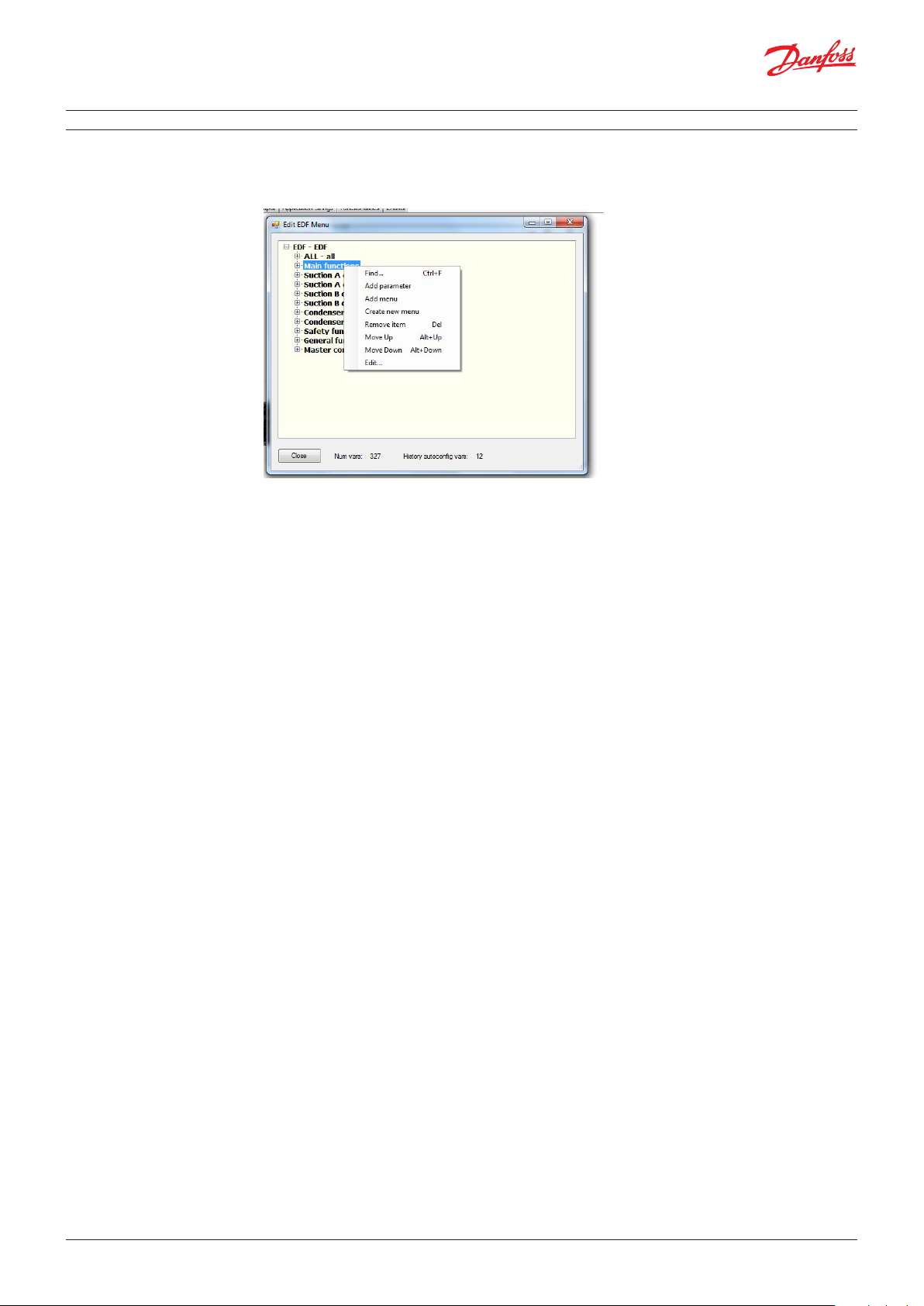
8.3 Edit EDF menu
The EDF menu editor allows to edit EDF groups for layout 1, 2 and 3 (ED3).
Press the “…” button to enter the menu editor
The context menu (mouse right-click) allow to:
• Find menu or parameter in the tree
• Add one parameter
• Remove one parameter or menu
• Create a new menu/sub-menu
• Clone a menu
• Move items up/down (keyboard shortcuts are handy)
• Edit parameter’s properties
If you want to clone an entire menu, remember that this will not be linked to the original menu, i.e. if
you later change the original menu, this will remain unchanged.
The “Num vars” counter will tell you how many variables you are exporting, and can be used as a
reference, because some front-end devices may not support high number of variables in the file.
The “History autoconfig vars” counter will tell you how many variables you have configured for auto
history.
The EDF menu editor and ED4 menu editor are very similar, but EDF has more restriction than ED4.
Adding variables to the “all” group will show them in all groups in the SM850.
You can add up to 15 groups (or submenus). If you try to add one, you will get an error message.
You can’t add a submenu to a menu.
You can’t remove the ALL group, as it is a “special” group.
The “Tag” column represents the tag available to the supervisor. Double-click on the “Value” column,
and the “Select Variable” form will be displayed. Parameters and status variables can be selected on
this form to be used by the supervisor.
© Danfoss | DCS (ADAP-KOOL®) | 2019.01
DKRCC.PS.RJ0.E4.02| | 37
Page 38

User manual | MCXShape standard software
8.4 Find in the EDF menu
The find menu for EDF tree can search in parameters and menu properties.
In the search toolbox, check the “Search in all column” flag to enable this function.
If the option is not checked, only visible text (menu label and description) will be searched.
If the option is checked, search will be extended to other properties. When a match is found, you can
edit the item properties to see all properties.
8.5 Edit parameter properties in EDF menu
The edit menu option allows you to edit properties for a specific parameter.
The datalogging combo box allow you to define (for each variable) if the history is enabled by default,
if it is possible to enable it (available) or if the user can’t enable it (e.g. for internal registers).
Remember: the properties are related to the variable, so if the same variable is available in multiple
menus, editing in one menu will also update the same variable in other menus.
© Danfoss | DCS (ADAP-KOOL®) | 2019.01
DKRCC.PS.RJ0.E4.02 | 38
Page 39

User manual | MCXShape standard software
8.6 Menu & Parameters tab
When EDF has been enabled, you will see a few more columns in the Menu & Parameters grid:
EDF r/o is used to force a variable to be read only in the EDF file, so that SM800 will not be able to
overwrite it.
EDF AppMode is used for backward compatibility and must be left blank.
8.7 EDF generation When you press the “Generate & Compile” button, a new folder called ADAP-KOOL is created within the BIN or App folder. It contains another folder EDF where you can find the EDF files.
9.0 CDF file generation
This is only for developers.
MCXShape automatically generates the CDF descriptor file. This can be used by external applications
(supervisory systems, touchscreen interfaces, etc.) to get information on the data shared by the
device.
When you press the “Generate & Compile” button, a new folder called ADAP-KOOL is created within
the BIN or App folder. It contains another folder EDF where you can find the CDF file.
© Danfoss | DCS (ADAP-KOOL®) | 2019.01
DKRCC.PS.RJ0.E4.02| | 39
Page 40

Danf
oss can accept no responsibility for possible errors in catalogues, brochures and other printed material. Danfoss reserves the right to alter its products without notice. This also applies to products
already on order pro
All trademarks in this material are property of the respec
vided that such alterations can be made without subsequential changes being necessary eady agreed.
tive companies. Danfoss and the Danfoss logotype are trademarks of Danfoss A/S. All rights reserved.
© Danfoss | DCS (ADAP-KOOL®) | 2019.01
DKRCC.PS.RJ0.E4.02 | 40
 Loading...