

Page 1

User Guide
User Guide
MCXDesign visual programming tool
ADAP-KOOL® Refrigeration Control System
www.danfoss.com
Page 2

User Guide | MCXDesign visual programming tool
Contents
Table of new contents ....................................................................................3
1.0 MCXDesign setup ...................................................................................4
2.0 MCXDesign first steps ...........................................................................4
2.1 Run ...................................................................................................4
2.2 MCXDesign project ........................................................................4
2.2.1 MCXShape and MCXDesign ...........................................5
2.2.2 Open a project .....................................................................5
2.2.3 Create a new project .........................................................5
2.2.4 Create a new library ...........................................................6
2.2.5 Open a library ...................................................................... 6
2.2.6 Import an existing library ................................................6
2.2.7 Update an existing project
made with a previous version of MCXDesign ..........7
3.0 MCXDesign workbench .......................................................................7
3.1 Area 1 - Resources/Components/Projects .............................7
3.1.1 Resources ..............................................................................7
3.1.2 Components ........................................................................8
3.1.3 Projects ................................................................................ 10
3.2 Area 2 - Working area ................................................................. 10
3.2.1 ”Electric Wiring” view ..................................................... 11
3.2.2 ”Logic” view ....................................................................... 11
3.2.3 ”User Interface” view ......................................................11
3.3 Area 3 – Property window ........................................................ 12
4.0 Debugger ................................................................................................ 13
5.0 HOW TO... ................................................................................................ 14
5.1 HOW TO create the PK application file for MCX ................14
5.2 HOW TO manage alarms ........................................................... 14
5.3 HOW TO add a resource ........................................................... 14
5.4 HOW TO create a special component...................................16
5.4.1 HOW TO create a Hotspot ............................................16
5.4.2 HOW TO create a Component ..................................... 16
5.4.3 HOW TO create a Brick ................................................... 17
5.4.4 HOW TO create a Box .....................................................18
5.4.5 HOW TO create a Frame ................................................ 19
5.4.6 HOW TO create a Screen ............................................... 19
5.5 HOW TO change the blocks’ execution order .................... 19
5.6 HOW TO manage commands .................................................. 20
5.7 HOW TO create your User Interface ...................................... 20
5.7.1 HOW TO create a Screen ............................................... 20
5.7.2 HOW TO create a loop of screens ..............................23
5.7.3 HOW TO associate a screen to a menu line ............ 23
5.7.4 HOW TO manage Icons..................................................24
5.7.5 System ON/OFF ................................................................ 25
5.8 HOW TO configure I/Os ............................................................. 25
5.8.1 Analogue Input ................................................................ 27
5.8.2 Digital Input and Digital Output ................................ 28
5.8.3 Analogue Output ............................................................ 28
5.9 HOW TO add an expansion ...................................................... 29
5.10 HOW TO search for a resource ................................................ 30
5.11 HOW TO manage Persistent (Eeprom) variables .............. 30
5.12 HOW TO manage internal EEV driver
(for MCX061V and MCX152V) ................................................. 32
5.13 HOW TO make a MODBUS master application ................. 33
5.14 HOW TO enable MODBUS Slave
on the second RS485 when available...................................34
5.15 HOW TO enable MODBUS TCP communication on
MCX15-20B2 controllers ........................................................... 34
5.16 HOW TO manage Datalogging on ......................................... 34
MCX15-20B2 controllers ........................................................... 34
5.17 HOW TO edit project configuration files ............................. 34
6.0 Release a Project (authorized users only) ................................ 35
7.0 FAQ ............................................................................................................ 35
© Danfoss | DCS (vt) | 2019.122 | BC326629593205en-000101
Page 3

User Guide | MCXDesign visual programming tool
Table of new contents
Manual
Version
Y2 V2.01 5.11 HOW TO manage Persistent (Eeprom) variables
Y3 V3.00 2.2 MCXDesign project
MCXDesign
Software
Version
New Contents
5.9 HOW TO add an expansion
5.8 HOW TO configure I/Os:
Note about physical input/output and virtual functions.
5.12 HOW TO manage internal EEV driver (for MCX061V and MCX152V)
5.13 HOW TO make a MODBUS master
6.0 Release a Project (authorized users only)
For releasing a project use the menu Tools Release
For a detailed description on how to use it, refer to the help online FAQ:
added some Q/A.
Updated figures
3.1.1 Resources
3.1.3 Project
5.4.1 HOW TO create a Hotspot
5.5 HOW TO change the blocks’ execution order
5.7.1 HOW TO create a Screen
5.7.4 HOW TO manage Icons
5.8 HOW TO configure I/Os
5.8.1 Analogue Input
5.13 HOW TO make a MODBUS master application
6.0 Release a Project (authorized users only)
For releasing a project use the menu Tools Release
For a detailed description on how to use it, refer to the help online FAQ.
This version V4.00 6.0 Release a Project (Repository)
5.15 HOW TO enable MODBUS TCP communication on MCX15-20B2 controllers
5.16 HOW TO manage Datalogging on MCX15-20B2 controllers
5.4.4 HOW TO create a Box: brick Skipbox
5.8 HOW TO configure I/Os: Easy switch among MCX15-20B-PV2-B2 models
5.8.1 Analogue Input: New AIs type
5.17 HOW TO edit project configuration files
© Danfoss | DCS (vt) | 2019.12 BC326629593205en-000101 | 3
Page 4

User Guide | MCXDesign visual programming tool
1.0 MCXDesign setup
2.0 MCXDesign first steps
1. From www.danfoss.com/mcx download the MCXDesign programming tool
2. Run MCXDesign setup and follow the indications (it is a good idea to keep the proposed installation
folders)
There is no need to install any other element, as all the necessary software tools are automatically
installed.
2.1 Run
To run MCXDesign double click on the icon on the desktop or select MCXDesign in the
MCXTools folder of the Start Menu folder.
If you do not have a licence you have three months’ free trial from the installation date. The expiry date
is displayed in the bottom right corner of the ”About” window that you can view by pressing “About”
menu.
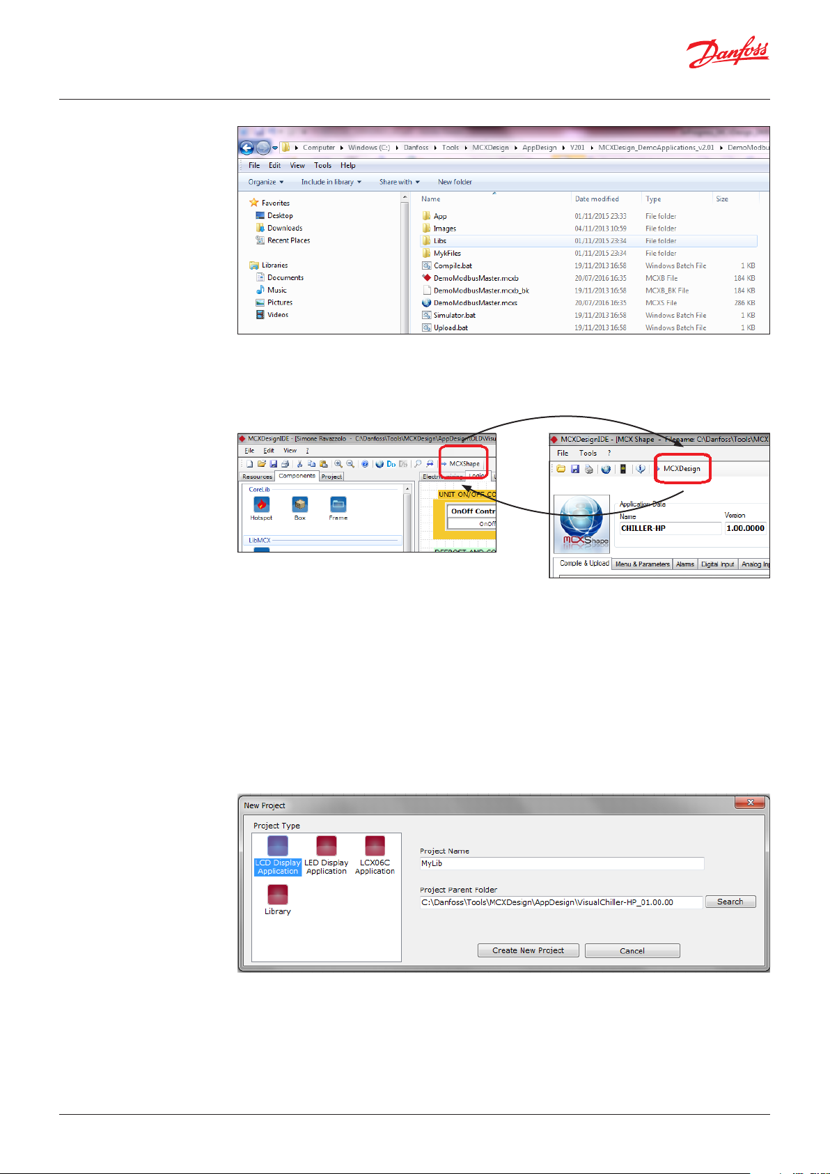
2.2 MCXDesign project
A project in MCXDesign is made of:
• MCXDesign project file (e.g. DemoApp.mcxb) and its backup (e.g. DemoApp.mcxb_bk)
• MCXShape configuration file (e.g. DemoApp.mcxs)
• Folder ”App” with application source files, libraries and icons
• Folder ”Libs” with all the libraries of graphic elements used in the project
• Folder ”MyKFiles” with the file to be loaded into the MMIMYK accessory to transfer the application
software into the MCX controller
• Folder “Images”: not used
• Other files (*.bat) used by MCXDesign
© Danfoss | DCS (vt) | 2019.124 | BC326629593205en-000101
Page 5
User Guide | MCXDesign visual programming tool
2.2.1 MCXShape and
MCXDesign
2.2.2 Open a project
2.2.3 Create a new project
• You can toggle between MCXDesign and MCXShape by pressing the command ”MCXShape” or
”MCXDesign” in the right part of the menu bar.
• Refer to the specific documentation for information about MCXShape usage
To open an existing project:
• Go to MCXDesign
• Select ”File Open” and select the *.mcxb file (e.g. DemoApp.mcxb)
• A backup copy of the *.mcxb and *mcxs file is automatically created into the Backup folder. The last
five back-up copies are maintained.
To create a new project:
• Go to MCXDesign
• Select ”File New”
• Select the icon for the type of application you are interested in: MCX with LCD display, MCX with
LED display, LCX06C
• Give a name to the new project and select the working folder (in a local path) where you have all the
projects
•
•
•
• Click on ”Create New Project”. This opens a new project with some elements already managed,
as per our default template (menu, few parameters, keyboard, alarms, alarm history, a few virtual
functions just as an example) in order to help you to get started.
© Danfoss | DCS (vt) | 2019.12 BC326629593205en-000101 | 5
Page 6

User Guide | MCXDesign visual programming tool
2.2.4 Create a new library
2.2.5 Open a library
A library is a collection of graphical logic blocks. To create a new library:
• Go to MCXDesign
• Select ”File New”
• Select the icon ”Library”
• Give a name to the new library folder in ”Project Name” and select the ”Libs” folder of the project
where you want to file the library.
Note: It is mandatory to have all the libraries in the ”Libs” folder.
A new folder with the name of your library is created inside the ”Libs” folder.
This folder will store all the files related to the elements of your library.
• Create the elements (bricks or components) of your library (see 3.1.2 Components)
• Save and reopen the project which the library belongs to in order to see the changes
To open an existing library:
• Go to MCXDesign
• Select ”File Open”
• Select the *.mcxlib type of files
• Select the desired library in the ”Libs” folder of your project (e.g. MyLib.mcxlib)
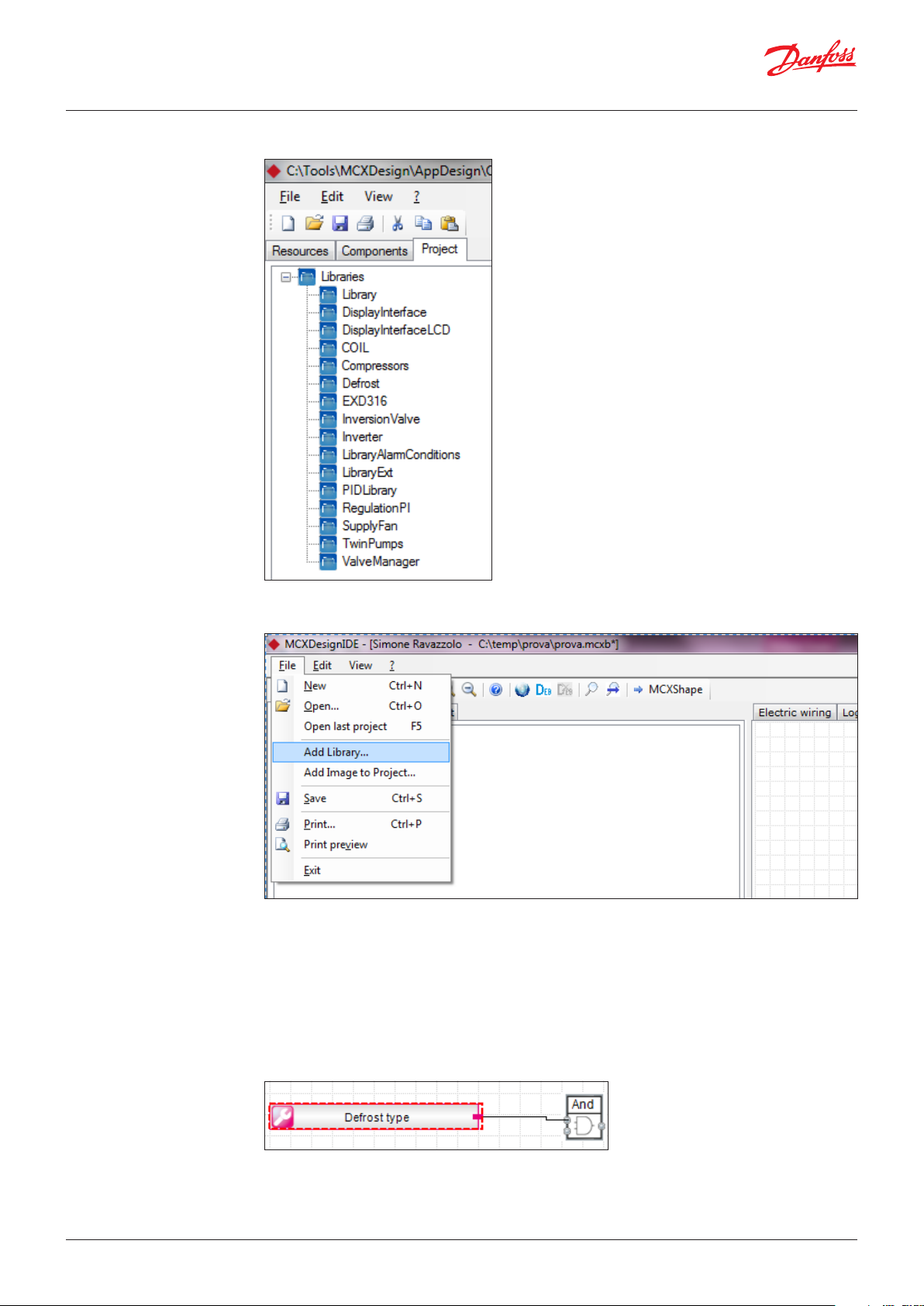
2.2.6 Import an existing library
• Go to MCXDesign
• Select ”File Add Library” and browse to the folder where the library is stored. The library will be
automatically copied into the ”Libs” folder of the current project. The project is then reloaded in
order to make the new library available.
Note: Libraries can be copied from one project to another simply by copying the related folder from
the ”Libs” folder of one project to the ”Libs” folder of the another.
© Danfoss | DCS (vt) | 2019.126 | BC326629593205en-000101
Page 7
User Guide | MCXDesign visual programming tool
2.2.7 Update an existing project
made with a previous
version of MCXDesign
3.0 MCXDesign workbench
To open and update an existing project made with a previous version of MCXDesign:
• Go to MCXDesign
• Select “File Open” and select the *.mcxb file of the existing project (e.g. DemoApp.mcxb)
• Select “File Open” and select “Update System“ libraries to update the system libraries in the project.
It is recommended to make a copy of the project before updating the system libraries.
Note: That the InitDefines.c file is updated in a smart way, keeping the customization you did.
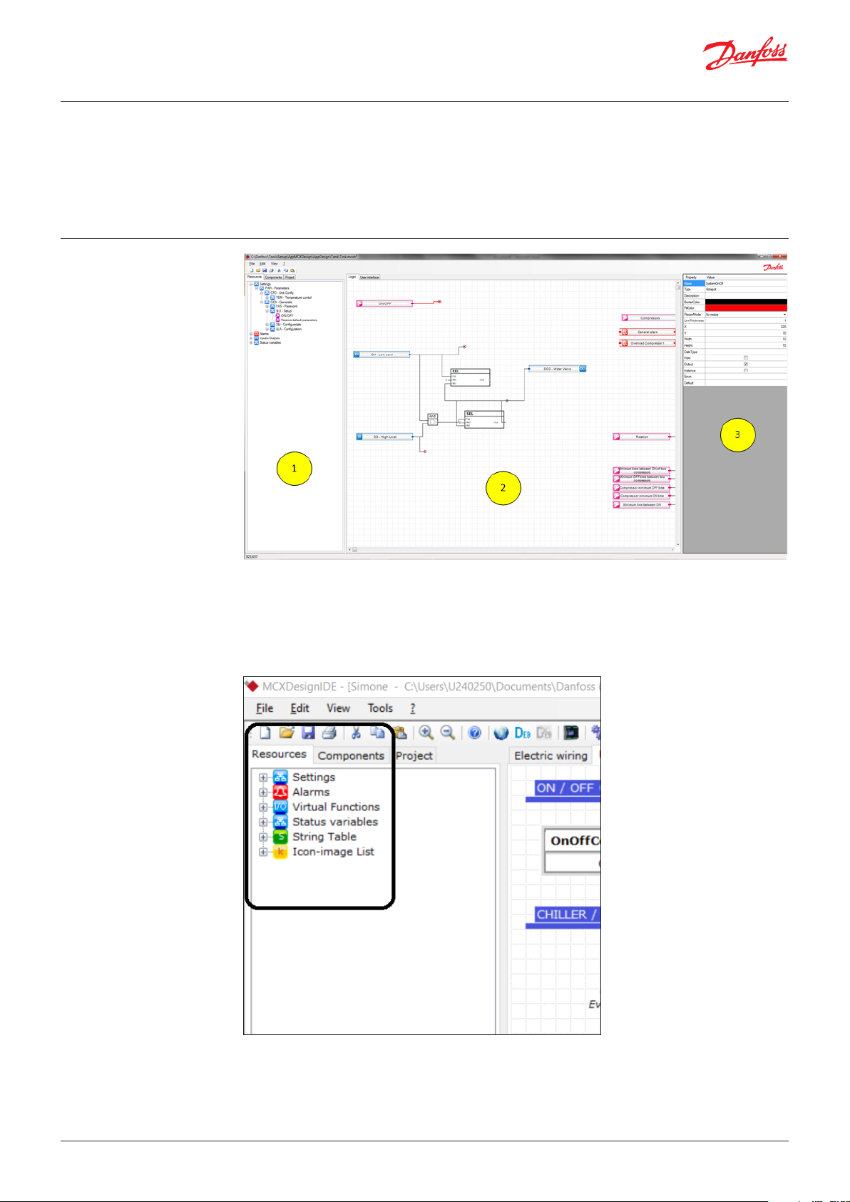
3.1 Area 1 - Resources/
Components/Projects
3.1.1 Resources
The MCXDesign working area is made of three parts.
List of all the available resources for the project: parameters, alarms, virtual functions, status variables,
strings, icons, parameter and alarm unique identifiers.
© Danfoss | DCS (vt) | 2019.12 BC326629593205en-000101 | 7
Page 8
User Guide | MCXDesign visual programming tool
Resources are created with MCXShape and MCXDesign.
• To add Parameters, Alarms and Strings, select ”MCXShape” and add them from there (see 5.3 HOW
TO add a Resource)
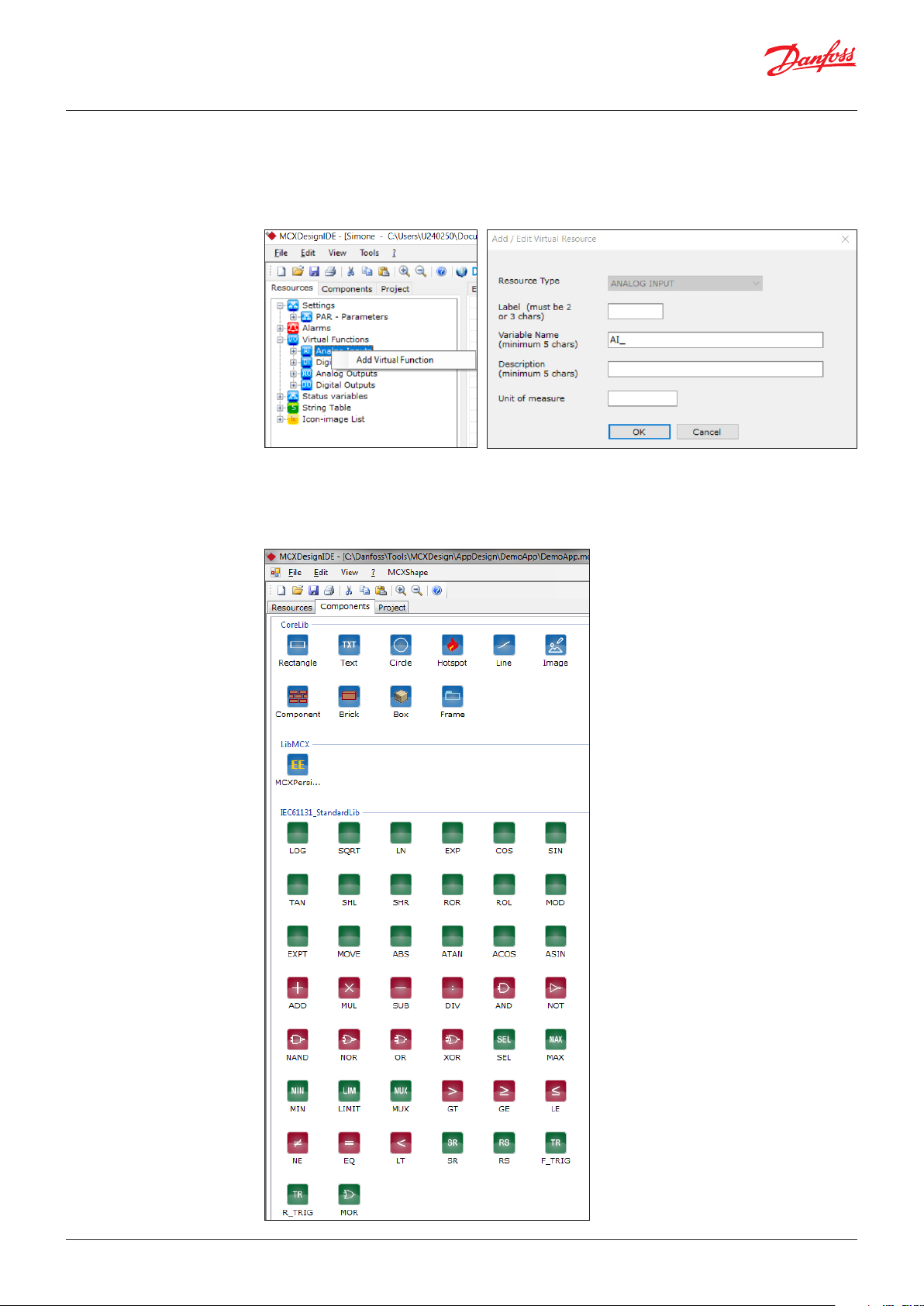
• To add Virtual Functions for I/Os, right-click over the desired Virtual Functions type on the Resources
panel of MCXDesign and fill in the form with the relevant information.
• To add Status Variables just add a Hotspot to the Logic sheet (see 3.1.2 Components)
3.1.2 Components
List of all the available components for designing your application software.
Components are grouped into libraries. There are some libraries delivered together with MCXDesign
and some others are related to a project and are loaded when the project is open.
© Danfoss | DCS (vt) | 2019.128 | BC326629593205en-000101
Page 9
User Guide | MCXDesign visual programming tool
• Red icons: basic logic blocks (e.g. AND, OR, etc.)
• Green icons: advanced logic blocks
• Blue icons: basic drawing tools, and some special components
• For each component there is an online help which explains its features. To access the online help,
select the component and press F1.
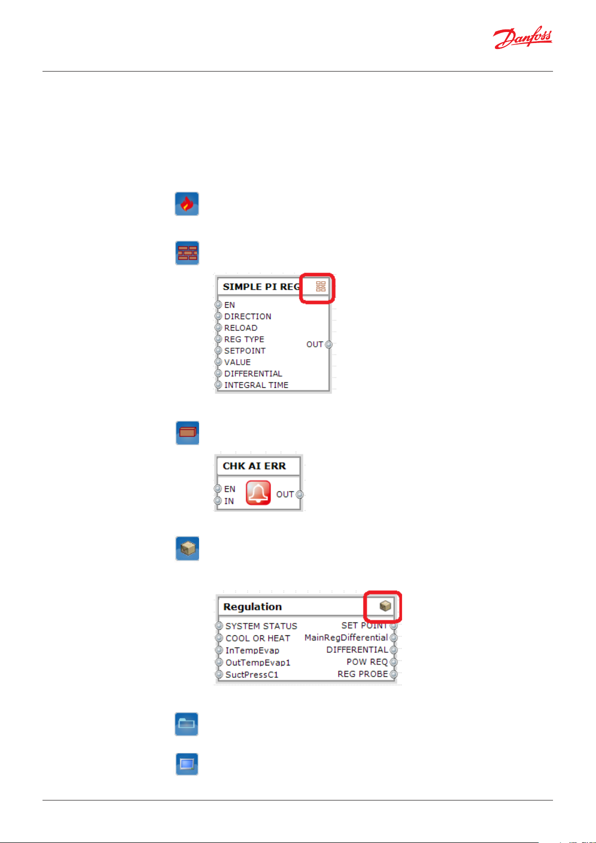
There are some special blocks in the CoreLib library that need a special description for their specifics
and importance in building the control strategy.
The special components are as follows:
A ”Hotspot” is a variable in RAM that is automatically exported to CAN and MODBUS networks.
Hotspot are also used to define input and output of the logic blocks and internal status
Hotspot
See 5.4.1 HOW TO create a Hotspot.
variables.
A Component is an element used to create a new component made of basic logic blocks.
A component is a part of a library which can be reused through all your projects.
A component is marked with a wall icon in the upper right corner.
Component
See 5.4.2 HOW TO create a Component.
A Brick is a component whose strategy is written in C++.
A Brick is a part of a library and can be reused through all your projects.
A Brick has no icon in the upper right corner.
Brick
See 5.4.3 HOW TO create a Brick.
A Box is a way of grouping together a part of logic made not only by bricks or components
but also including parameters, input and output.
A Box is not part of a library but is a part of your project. To reuse a Box in other projects
Box
you can simply cut and paste it.
A Box is marked with a box icon in the upper right corner.
See 5.4.4 HOW TO create a Box.
A Frame is a way of defining a comment to a piece of logic and is useful for describing its
features.
See 5.4.5 HOW TO create a Frame.
Frame
A Screen is a special component available only in the User Interface view. It is used to
create loops of user interface screens.
See 5.4.6 HOW TO create a Screen.
Screen
© Danfoss | DCS (vt) | 2019.12 BC326629593205en-000101 | 9
Page 10
User Guide | MCXDesign visual programming tool
3.1.3 Project
List of all the libraries that are used in the project.
3.2 Area 2 - Working area
To add or remove a library, access the ”Libs” project folder where all the libraries are stored.
You can also add a library from menu “File Add Library…”
Space where you can design the I/O Configuration, the control logic and the user interface of your
application.
Drag and drop here the elements taken from the ”Resources” and ”Components” groups.
Note:
• Ctrl + scroll wheel of your mouse to zoom
• Hold the mouse scroll wheel to move the drawing
• To delete a line, move the end of the line away from its connection point
• To add a line, drag the mouse from left (output of a component) to right (input of another
component)
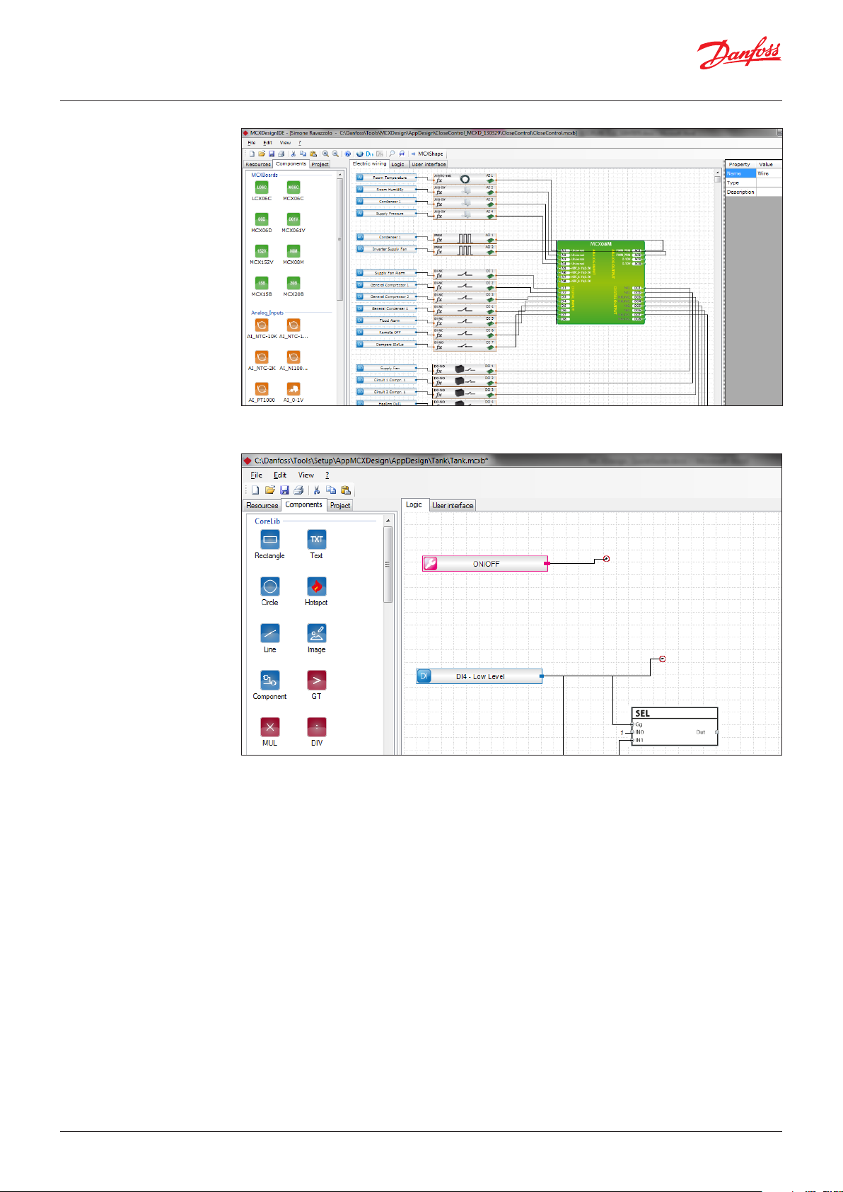
MCXDesign is made up of three views:
• ”Electric Wiring” view for designing the Input/Output configuration
• ”Logic” view for designing the control logic
• ”User Interface” view for designing the User Interface
© Danfoss | DCS (vt) | 2019.1210 | BC326629593205en-000101
Page 11
User Guide | MCXDesign visual programming tool
3.2.1 ”Electric Wiring” view
Define the type of each MCX’s physical input and output and assign a virtual function to it.
For more info see 5.8 HOW TO configure I/Os.
3.2.2 ”Logic” view
Connect the elements together in the ”Logic” view to design your control logic.
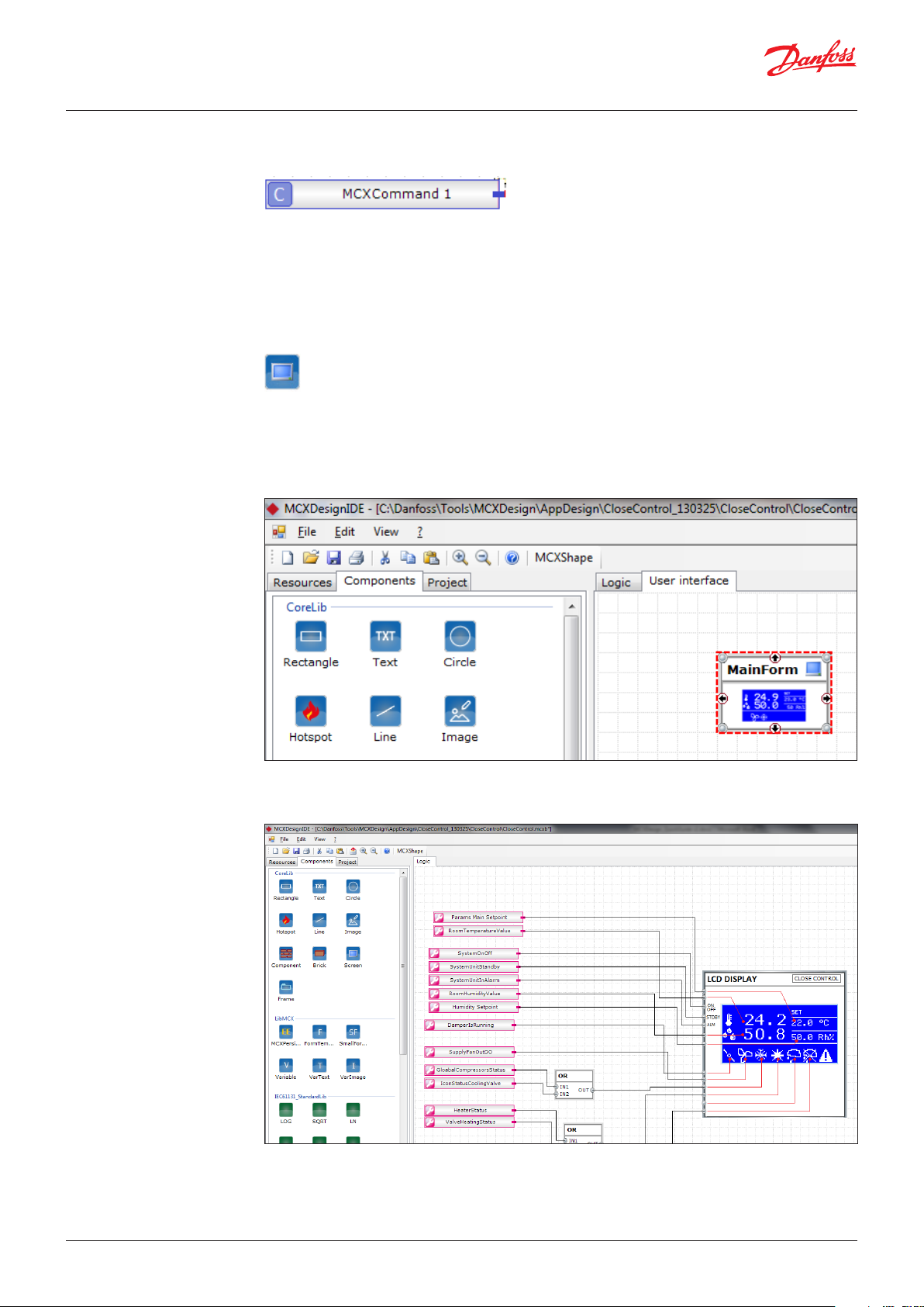
3.2.3 ”User Interface” view
© Danfoss | DCS (vt) | 2019.12 BC326629593205en-000101 | 11
Place and eventually connect the screen elements in the ”User Interface” view to design your user
interface.
See 5.7 HOW TO create your User Interface.
MENU and KEYBOARD
The menu appearance and the usage of some keys are defined by a standard template and cannot be
modified using MCXDesign.
The menu elements and their position in the menu tree are defined with MCXShape.
Main keys’ function in the main screen
• UP, DOWN, RIGHT, LEFT are used to navigate through the loop of screens according to what is
defined in MCXDesign
• ENTER to access the Main Menu
• X to access the Alarm Screen with the alarms list
• UP held for 3s to switch the unit ON or OFF
In the Alarm Screen
• X to exit
• ENTER held for 3s to reset manual alarms
Page 12

User Guide | MCXDesign visual programming tool
In the Main Menu screen
• UP and DOWN to scroll through the menu
• ENTER to go one level down in the menu tree or enter into Edit Mode
• X to go one level back in the menu tree
In Edit Mode
• UP and DOWN to edit the value
• ENTER to save and exit from edit mode
• X to exit from edit mode without saving
3.3 Area 3 – Property
window
Property window of each component or of the project.
To see the properties of an element, select it on the design sheet.
© Danfoss | DCS (vt) | 2019.1212 | BC326629593205en-000101
Page 13

User Guide | MCXDesign visual programming tool
4.0 Debugger
Run the Debugger by clicking on the button in the toolbar.
Click on to stop it.
When you run the Debugger:
• The Simulator is executed
• The Property window is used to show the input/output data of the selected element in the logic
sheet. The new function of the Property Window is signalled by the colour yellow.
Note:
• Remember to stop the Debugger before changing the control logic
• To see the values of User Interface data you must be in the right context. This means that you must
watch for the form that you want to debug on the simulator.
© Danfoss | DCS (vt) | 2019.12 BC326629593205en-000101 | 13
Page 14

User Guide | MCXDesign visual programming tool
5.0 HOW TO...
5.1 HOW TO create the PK
application file for MCX
5.2 HOW TO manage alarms
5.3 HOW TO add a resource
There are two ways:
1. Click the Save and Compile button on the MCXDesign toolbar
2. Generate & Compile from MCXShape
Note:
• The PK file is created inside the BIN folder
• You can run simulator, etc from MCXShape as before. See specific documentation about MCXShape.
• You can run the Debugger from MCXDesign
Alarms are configured in MCXShape. You set the alarm name, reset type, delay and actions in the MCXShape.
When you drag an alarm from the ”Resources” into the logic area you retain all these settings.
You simply have to define the trigger condition (see next picture).
Some resources can be added from MCXShape and others from MCXDesign.
From MCXShape you can add parameters, alarms and strings.
From MCXDesign you can add virtual functions for I/O and status variables.
To add a new resource from MCXShape:
• Go to MCXShape
• Right-click over the Menu & Parameters, Alarms or Applications Strings area in MCXShape and add/
change/delete the resource.
E.g. to add a parameter:
© Danfoss | DCS (vt) | 2019.1214 | BC326629593205en-000101
Page 15

User Guide | MCXDesign visual programming tool
E.g. to add a string
• SAVE changes
If now you go back to MCXDesign by clicking on the MCXDesign command that you will find in the
MCXShape menu bar, you will see the new resources available for the project.
To add a new resource from MCXDesign:
• To add Virtual Functions for I/Os, right-click on the Resources panel of MCXDesign
• To add Status Variables, just add a Hotspot on the Logic sheet (see 3.1.2 Components)
Note:
When you add a new resource (parameter, string, alarm, virtual function), you also must define the
name of the variable that will be used inside the code and that must be unique. It is suggested to use
the following name conventions and to start the names with these prefixes:
Parameters: Params_*** (e.g. Params_Setpoint)
Alarms: AL_*** (e.g. AL_HighPressure)
Strings: DESCR_*** (e.g. DESCR_String)
Analogue Input virtual function: AI_*** (e.g. AI_Temperature)
Analogue Output virtual function: AO_*** (e.g. AO_Inverter)
Digital Input virtual function: DI_*** (e.g. DI_MainSwitch)
Digital Output virtual function: DO_*** (e.g. DO_Compressor1)
© Danfoss | DCS (vt) | 2019.12 BC326629593205en-000101 | 15
Page 16

User Guide | MCXDesign visual programming tool
5.4 HOW TO create a special
component
5.4.1 HOW TO create a Hotspot
A ”Hotspot” on the main logic sheet (not inside a Box or a Component) is a variable in RAM
automatically exported to CAN and MODBUS networks.
Hotspots are also used to define input and output of the logic blocks and internal status
Hotspot
variables.
To add a hotspot, follow the steps below:
1. Drag the hotspot into the working area
2. Assign the hotspot a name in the Property window
3. Assign the hotspot a DataType (INT, BOOL, etc) in the Property window
Available DataTypes Size Description
BOOL 1 byte Boolean value. It can take one of two values: 0 or 1.
INT 2 bytes Integer
UINT 2 bytes Unsigned Integer
DINT 4 bytes Double Integer
4. Assign the hotspot a type from Input, Output, Instance, ticking the right check box in the Property
window. Instance means an internal variable that is neither input nor output.
5. Connect the hotspot to the component you want (draw a line from the component to the hotspot)
To delete connection from a hotspot, select the hotspot and right-click to open the context menu.
5.4.2 HOW TO create a
Component
A Component is an element used to create a new component made of basic logic blocks.
A Component is a part of a library.
A Component is marked with a wall icon in the upper right corner.
Component
© Danfoss | DCS (vt) | 2019.1216 | BC326629593205en-000101
Page 17

User Guide | MCXDesign visual programming tool
To create a new Component, follow the steps below:
1. Open an existing library or create a new one
Note: You can run a new instance of MCXDesign to create a new component.
2. Drag a component into the working area and double-click on it to enter the logic design view for
that component.
3. Place the hotspots you need
4. Design your logic, e.g.
5. Exit from the Component creation mode using the button on the toolbar
6. Give a new name to the component in the Property window
7. Save and exit
8. Reopen the project to see the new library and/or component
5.4.3 HOW TO create a Brick
A Brick is a component whose strategy is written in C++.
A Brick is a part of a library.
A Brick has no icon in the upper right corner.
Brick
To create a new Brick, follow the steps below:
1. Open an existing library or create a new one
Note: You can run a new instance of MCXDesign to create a new Brick.
2. Drag a Brick into the working area and double-click on it to enter the logic design view for that
component.
3. Give a name to the Brick (e.g. MyNewBrick).
Pay attention that the name of the Brick must be a valid name for a class in C language (no spaces
allowed).
4. Place the Hotspots that you need to define the input and output of the Brick, e.g.
5. Eventually place the Persistent variables you need. Persistent variables are variables that are stored
in non-volatile memory. Persistent variables are loaded from Eeprom at start-up and are saved
when the special BOOL ”Save” variable is set to 1 (see 5.11 HOW TO manage Persistent (Eeprom)
variables).
6. Exit from the Brick creation mode using the button on the toolbar
7. Save (and generate the code)
8. Go into the library folder and edit the file <name_of_the library>_Brick.c with your C++ editor.
Note: The *_Template.c file is automatically generated at each save, therefore use it only as
inspiration. All your logic must be inserted into the <name_of_the library>_ Brick.c file which is
created only once.
© Danfoss | DCS (vt) | 2019.12 BC326629593205en-000101 | 17
Page 18

User Guide | MCXDesign visual programming tool
5.4.4 HOW TO create a Box
9. Finally, add into the library folder the images to be shown inside the brick (img<name_of_the_
brick>.png) and in the Resources tree (<name_of_the_brick>.png).
A Box is a way of grouping together a part of logic made not only by bricks or components,
but which also includes parameters, input and output.
A Box is not part of a library but is a part of your project. To reuse a Box in other projects
Box
you can simply cut and paste it.
A Box is marked with a box icon in the upper right corner.
To create a Box, follow the steps below:
1. Drag and drop the Box component into your working area
2. If you have already designed the logic that you want to include in the Box, select the elements that
you want to be put into the Box; otherwise go to point 4.
3. Right-click and cut or copy the selected elements
4. Double-click on the Box to open it
5. Paste the elements or create a new logic inside the Box
6. Exit from the Box creation mode by using the button on the toolbar.
Once created, you can open a Box by double clicking it.
If you place the EnableDisableBox brick inside the Box, you can connect the Box with a
Functionality defined in the Functionality Tab of MCXShape. When that Functionality is not
Enable
Disable
Box
To connect a box with a Functionality, see the Help of the EnableDisableBox.
enabled, the software code defined in the Box is not compiled. It is used to save memory
resources in complex applications.
If you place the SkipBox brick inside the Box, you can skip the execution of the software
code defined in the Box when it is not enabled. It is used to reduce the main loop time of
SkipBox
The use of this brick does not reduce the memory used by your application (see
your application.
EnableDisableBox).
© Danfoss | DCS (vt) | 2019.1218 | BC326629593205en-000101
Page 19

User Guide | MCXDesign visual programming tool
5.4.5 HOW TO create a Frame
5.4.6 HOW TO create a Screen
A Frame is a way of defining a comment to a piece of logic, which is useful to describe its
features.
Frame
To create a Frame, follow the steps below:
1. Drag and drop the Frame element into your working area
2. Drag the bottom right corner of the Frame to resize it and move the Frame behind the logic you
want to highlight.
3. Using the Property window of the Frame, define the Frame’s appearance; and set the Description
and FillColor fields, e.g.
A Screen is a special component available only in the User Interface view. It is used to
create loops of user interface screens.
A Screen is like a Box but contains a screen and eventually some logic. As with a Box, it can
Screen
be opened by double-clicking it.
A Screen is characterised by having some special hotspots used for creating a loop of
Screens.
See the next section for information on how to create a Screen.
5.5 HOW TO change the
blocks’ execution order
To view the logic of the blocks’ execution order and/or to change it, right-click anywhere in your
current logic view and select ”Execution Order”.
A new window will open showing the list of all the logical blocks and hotspots used in the current
logic view, sorted according to their execution order.
You can change the position of the elements in the list, thus changing their execution order in two
ways. Select one element in the list and use the ”Move Up” and ”Move Down” buttons to position the
element in the desired place or use the “Move to Index” button to move the element directly to the
specified position.
© Danfoss | DCS (vt) | 2019.12 BC326629593205en-000101 | 19
Page 20
User Guide | MCXDesign visual programming tool
5.6 HOW TO manage
commands
5.7 HOW TO create your
User Interface
5.7.1 HOW TO create a Screen
To send a command to a block, use the MCXCommand element in the LibMCX library and connect it
to the input of the block.
Right-click on the MCXShape menu and Edit an existing menu line or create a new one; in the OUT
Code field, type the same name of the MCXCommand.
When this menu line is selected and executed, an impulse will be sent to the block input where the
MCXCommand is connected.
A Screen is a special component only available in the User Interface view. It is used to
create loops of user interface screens.
A Screen is like a Box but contains a display screen and eventually some logic. As with a
Screen
Box, it can be opened by double clicking it.
A Screen is characterised by having some special hotspots used for creating a loop of
Screens.
To create a Screen, follow the steps below:
1. From the CoreLib library, drag and drop the Screen component into your working area
2. Double-click on the Screen to open it
3. Drag the User Interface components you want to put into the Screen into the screen working area.
You can use ready-prepared templates or create your own custom screen.
© Danfoss | DCS (vt) | 2019.1220 | BC326629593205en-000101
Page 21

User Guide | MCXDesign visual programming tool
The User Interface components that you can use are the following:
• LCD and LED display templates already prepared for MCX display, taken from the
DisplayInterfaceLCD and DisplayInterfaceLED libraries.
Example of available templates:
© Danfoss | DCS (vt) | 2019.12 BC326629593205en-000101 | 21
Page 22
User Guide | MCXDesign visual programming tool
• Elements to create your own screen taken from the library LibMCX:
FormTemplate
To design your own screen for 128x64 pixel LCD displays (MCX08 or higher and MMIGRS)
If Fixed=0 in the Property window, you can move the form while keeping the other elements that
you have placed in the form fixed.
SmallFormTemplate
To design your own screen for 98x64 pixel LCD displays (MCX06D).
If Fixed=0 in the Property window, you can move the form while keeping the other elements that
you have placed in the form fixed.
Variable
To display a variable on your screen.
Set the following properties in the Property window:
• Name: name of the variable used in the source code
• Decimals: number of decimal places
• Font Size: 1 (small), 8 (normal ), 16 (large)
• Width: width of the variable
FormHorizLine
To draw a horizontal line.
Set the length of the line with the Width property in the Property window
FormVertLine
To draw a vertical line.
Set the length of the line with the Width property in the Property window
VarTe xt
To display a string into your screen. The text of the string can be written directly in the Property
window in the Value field, writing the text between double quotes.
However, to manage multiple languages, it is suggested to create the string in MCXShape. After
creating in MCXShape, the string will be available among the String Table Resources in MCXDesign
VarImage
To display an icon into your screen.
See 5.7.4 HOW TO manage icons
ProgressBar
To visualize the progress of an operation
4. Connects the hotspots of the elements above to resources in your project and eventually adds the
logic you need.
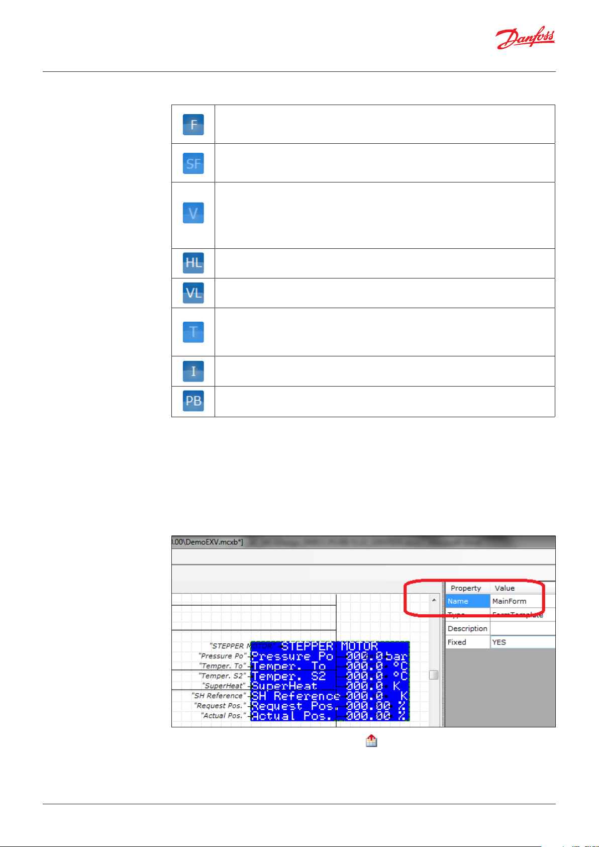
5. Give a name to the form.
If the name used here is also used in the OUT_CODE property of a menu line in MCXShape, then
the screen is linked to the menu (see 5.7.3 HOW TO associate a screen to a menu line).
Important Note:
At the minimum, your user interface is made up of a main screen, which is shown at start-up.
The main screen is defined by the name ”MainForm” in the Property window.
It is mandatory to have one MainForm.
6. Exit from the Screen creation mode by using the button on the toolbar (the name of the form
will be automatically assigned to the Screen).
© Danfoss | DCS (vt) | 2019.1222 | BC326629593205en-000101
Page 23

User Guide | MCXDesign visual programming tool
5.7.2 HOW TO create a loop of
screens
A loop of screens is a set of screens connected by the UP, DOWN, LEFT, RIGHT keys.
To create a loop of screens, follow the steps below:
1. Create the screens you need
2. Connect the screens in the desired order, drawing a connection line from the hotspot of the key
you want to use for navigating in the loop to any of the input hotspots of the next screen.
E.g. Loop made of two screens, UP and DOWN key to move from one to the other.
5.7.3 HOW TO associate a
screen to a menu line
You can add new screens or a loop of screens, associating them to specific menu lines, created with
MCXShape.
1. Right click on the MCXShape menu and edit an existing menu line or create a new one
2. In the field OUT Code, type the same name of your screen created with MCXDesign
© Danfoss | DCS (vt) | 2019.12 BC326629593205en-000101 | 23
Page 24

User Guide | MCXDesign visual programming tool
5.7.4 HOW TO manage Icons
1. Drag the VarImage component into the Screen
2. If you want to use one of the images already present in the project, jump to the next point.
If you want to create a new image, from menu “File Add Image to Project..” select the new bitmap.
It will be automatically copied into the App/image folder of your project and made available.
3. All the available images are listed in the “Icon-image List” within the Resources panel.
Drag the desired icon into the Screen and connect it to the IconIndex input of the VarImage
element.
4. Use the IconStatus input of the VarImage element to make it visible (1) or not (0)
Note:
• To change an image in a simple way you can simply edit an existing one with a Bitmap editor,
retaining its name.
• To delete an existing image (or change the name of an existing one) edit the ”images.xml” file inside
the ”images” folder.
© Danfoss | DCS (vt) | 2019.1224 | BC326629593205en-000101
Page 25

User Guide | MCXDesign visual programming tool
5.7.5 System ON/OFF
To function properly, the UI always needs the ”System ON/OFF” variable, even if it is not connected to
anything.
5.8 HOW TO configure I/Os
• Go to the Electric Wiring View
• From the Components panel, select the type of MCX you want to use and drag and drop it into the
working area.
Note:
• If you press F1 when the type of MCX is selected in the Electric Wiring view, the datasheet of the
corresponding MCX is displayed.
• If you right click over an MCX15x or MCX20x board, you can easily switch to another model through
the menu “Change Device”. All the valid I/O connections will be maintained, and you do not need to
rewire them. It is used to facilitate the switch to the new models: to the PV2 version with same I/Os
but additional memory or to the new generation of B2 controllers.
© Danfoss | DCS (vt) | 2019.12 BC326629593205en-000101 | 25
Page 26

User Guide | MCXDesign visual programming tool
• Define the type of each I/O connecting the available types to the physical I/O.
An automatic check of the connectable types is performed. It is not possible to assign a type that is
not managed by the specific hardware.
For example, AI2 is assigned to be NTC-10 K Ohm.
• Finally, assign a virtual function to the I/O.
Virtual functions are available in the Resources panel (see 5.3 - HOW TO add a Resource).
Virtual functions only refer to the input/output function (e.g. room temperature, compressor speed
control, fan speed control, etc.) without any reference to the physical location of the input/output in
the MCX.
© Danfoss | DCS (vt) | 2019.1226 | BC326629593205en-000101
Page 27

User Guide | MCXDesign visual programming tool
5.8.1 Analogue Input The following types of Analogue Inputs are available:
NTC-10K NTC 10K Ohm at 25 °C
NTC-100K NTC 100K Ohm at 25 °C
NTC-2K NTC 2K Ohm at 25 °C
NI1000TK5 NI 1000 Ohm at 0 °C
PT1000
4 – 20 mA
0 – 20 mA
0 – 1 V
0 – 5 V
0 – 5 V NOP
0 – 10 V
ON/OFF To use AI as DI
NTC-Tables
PT1000-Table
PT1000 HR
0 – 5 V Ratio
PT1000 Ohm at 0 °C
On MCX061V, MCX152V, MCX08M2, MCX15-20B2
use the input type PT1000_HR.
0/5 V without internal pull-up resistor for high
impedance inputs.
To add custom NTC (up to 3 types).
The NTC tables are in the file App/ IOUtils/
CustomNTCxParameters.c file in your project.
To add custom PT1000.
The PT1000 table is in the file App/ IOUtils/
CustomPT1000Parameters.c file in your project.
For PT1000 sensors on MCX061V, MCX152V,
MCX08M2, MCX15-20B2. Improved resolution.
For 0 – 5 V ratiometric sensors on MCX061V,
MCX152V, MCX08M2, MCX15-20B2. Improved
resolution.
Note: On the other MCXs use the brick 0 – 5 V
also for ratiometric types.
© Danfoss | DCS (vt) | 2019.12 BC326629593205en-000101 | 27
Page 28

User Guide | MCXDesign visual programming tool
Analogue input properties
When you configure Analogue Input, you must also set the following properties in the Property panel:
Decimals: number of decimals.
Minimum: minimum value that the input can assume.
Maximum: maximum value that the input can assume.
Overrange: 0 or 1. 0 means that it is not permitted to exit from the min-max range: an alarm is
generated in this case.
Per cent: only for active probes. Use Per cent=10 to reduce the input range of the probe by 10%.
Per cent=10 must be set for ratiometric pressure transmitters whose input ranges from 0.4 – 4.5 V.
5.8.2 Digital Input and Digital
Output
5.8.3 Analogue Output
You have two different objects to define Normally Open or Normally Closed contacts:
Note: You can easily switch from one type to the other after you have connected a normally open or
normally closed DI/DO by simply right-clicking on the object and selecting ”Invert Polarity”.
The following types of Analogue Outputs are available:
0 – 1 V
0 – 5 V
0 – 10 V
EXV Electronic Expansion Valve
PWM Pulse Width Modulation
PPM Pulse Position Modulation
FREQ Frequency Modulation
EXV
Electronic Expansion Valve (for MCX061V and
MCX152V only)
© Danfoss | DCS (vt) | 2019.1228 | BC326629593205en-000101
Page 29

User Guide | MCXDesign visual programming tool
5.9 HOW TO add an
expansion
The MCX and the expansion are connected via CANbus: they must be configured to have different
CAN ID and equal baud rate. Refer to the specific manual for the hardware requirements of a CANbus
network; remember to activate the R120 Ohm line termination on the first and last element of the
network by making a bridge (short circuit) between connectors CANH and R120 of the first and last
network nodes.
To add an expansion to your project:
• Go to the Electric Wiring View
• From the Components panel, in the MCXExpansions section, select the type of expansion you want
and drag and drop it into the working area.
Note:
• LCX06C is not able to manage an expansion (it is not equipped with CANbus communication). If you
add an expansion when your main board is LC06CX, you will get a warning at when compiling.
• You can use MCX061V and MCX152V as I/O expansions except for their EXV output.
Note: The word “Expansion” is added on the right of the expansion type to distinguish the expansion
board from the main board.
• Configure the expansion I/Os as you would do in a normal MCX
• In the Logic view it is suggested to add the ExpansionManager brick taken from the
ExpansionControlLib library. Without it, the expansion is supposed to have Node ID=10 and it is not
possible to generate an alarm in case of lost communication.
• Configure the Expansion Manager input pins:
– EN: expansion enable (0=NO, 1=YES)
– NODE ID: expansion address in the CANbus network (default=10)
• Connect the Expansion Manager output ERROR pin if you want to generate an alarm when the
communication with the expansion is not working. The ERROR pin must be connected to a special
alarm created in MCXShape, whose variable name is AL_Exp_NoLink.
© Danfoss | DCS (vt) | 2019.12 BC326629593205en-000101 | 29
Page 30

User Guide | MCXDesign visual programming tool
Example of “Expansion Manager” configuration:
For an exhaustive example of expansion usage download the application “DemoExpansion” from the
MCX FTP area.
5.10 HOW TO search for a
resource
5.11 HOW TO manage
Persistent (Eeprom)
variables
Select the resource you want to search for and press the search button on the toolbar.
The result is a message listing all the views where the resource is used.
Go to that view and press ”Search Next” to highlight the resource.
Persistent variables are variables that are stored in non-volatile memory (Eeprom). They can be created
only inside a Brick: see 5.4.3 HOW TO create a Brick.
Persistent variables are loaded from Eeprom at start-up and are saved when the special BOOL ”Save”
variable is set to 1. The value to be stored in Eeprom must be assigned to the special DINT ”Data” variable.
Example:
1. Add a persistent variable to a new brick as in the following example. The name of the variable must
be DATA.
2. Exit from the Brick creation mode using the button on the toolbar.
Save (and generate the code) using the button in the toolbar.
The resulting code after saving the library is in the LIBS folder and
is called <name_of_the_library>_Brick_Template.c. It looks like the following:
struct DemoCOUNTER
{
// public
BOOL EN;
DINT OUT;
BOOL RESET;
// private
DINT DATA; //copy of the value saved in eeprom
BOOLSAVE;//agtotriggerdatasavingineeprom
void Init()
{
}
void Main()
{
}
};
© Danfoss | DCS (vt) | 2019.1230 | BC326629593205en-000101
Page 31

User Guide | MCXDesign visual programming tool
3. Copy the template into the *_Brick.c file and add the logic you need.
Note: The *_Template.c file is automatically generated when the brick is saved, therefore just use it
as inspiration. All your logic must be inserted into the <name_of_the library>_ Brick.c file which is
created only once and will never be overwritten.
Example of how to store in non-volatile memory the running time (seconds) of one element of your
units. The time is saved every 20 minutes. Note that a higher frequency could affect the non-volatile
memory lifetime.
struct DemoCOUNTER
{
// public
BOOL EN; // enable counter
BOOL RESET; // reset counter
DINT OUT; // counter output
DINT DATA; //copy of the value saved in eeprom. NOTE: it’s a special
variable,don’tchangeit
BOOLSAVE;//agtotriggerdatasavingineeprom.NOTE:it’sa
specialvariable,don’tchangeit
// private
TTimerSec _tm; //timer declaration
BOOL _status;
// subclasses
void Init() {
_status = 0;
SAVE = 0;
}
void Main()
{
if(EN == 1) {
if(_status == 0) {
_tm.Start();
_status = 1;
}
if(_tm.ElapsedSec() > 20 * 60) { // save every 20 minutes
DATA=DATA+_tm.ElapsedSec();//updatewithlastcounting
SAVE = 1;
_tm.Start();
}
OUT = DATA + _tm.ElapsedSec();
}
else { // EN == 0
if(_status == 1) {
DATA=DATA+_tm.ElapsedSec();//updatewithlastcounting
_status = 0;
}
OUT = DATA;
}
if(RESET == 1) {
DATA = 0;
OUT = DATA;
SAVE = 1;
RESET = 0;
_tm.Start();
}
}
© Danfoss | DCS (vt) | 2019.12 BC326629593205en-000101 | 31
Page 32

User Guide | MCXDesign visual programming tool
5.12 HOW TO manage
internal EEV driver
(for MCX061V and
MCX152V)
For an example of how to manage the Electronic Expansion Valve driver, download the application
“DemoEXV” from the MCX FTP area at www.danfoss.com/mcx.
The main steps are the following:
1. In the Electric Wiring view select MCX061V or MCX152V: these are the MCX models equipped with
internal stepper motor drivers.
2. Configure the stepper motor output EXV1 and/or EXV2 connecting it to the AO_EXV analog output
type.
3. Define the virtual function associated to the output (Stepper Motor Position in the figure below).
4. In the Logic View use the StepperMotorDriver brick from the ExternalDevicesLib library to configure
the driver.
5. Now you can use your virtual function Stepper Motor Position to set the valve position.
As described in the following example, the valve position can be set by a parameter or by the result
of a calculation, like the one for controlling the Super Heat. In this case you can use the Super Heat
brick from the HVAC library. This library can be downloaded from the MCX FTP site. See 2.2.6 Import
an existing library for information about how to add a library to a project.
© Danfoss | DCS (vt) | 2019.1232 | BC326629593205en-000101
Page 33

User Guide | MCXDesign visual programming tool
5.13 HOW TO make a
MODBUS master
application
For an example of a MODBUS Master application download the application “DemoMODBUSMaster”
from the MCX FTP area at www.danfoss.com/mcx.
Important Note:
On MCX equipped with one RS485 serial ports you must add the following instruction in the file
InitDefines.c inside the App folder of your project: #define NO_COM. This instruction allows you to
use the serial port as MODBUS master but remember that now the port is not working anymore as
MODBUS slave. Therefore, you will be able to upload an application via RS485 into the MCX only in the
first five seconds after power up. After this period your new application will take control of the serial
communication.
All the bricks for building a MODBUS master application are inside the MCXMODBUSMasterLib library:
• MCXMODBUSMasterConfig is used to configure the MODBUS serial port
COM NUMBER=1 to use the RS485#1 in any MCX
COM NUMBER=2 to use the RS485#2 in MCX15 and MCX20
• MCXMODBUSMasterRead is used to read a group of consecutive variables (maximum 5). At the
NUMBER OF VALUES pin you specify the number of variables read by that brick.
If you want to read more variables you can add another MCXMODBUSMasterRead, but
you must connect it to the previous one through the OFFSET IN/OUT pins. Finally, each
MCXMODBUSMasterRead brick must have a unique and consecutive index at the INDEX input,
starting from 1.
In the example above, the brick with INDEX=1 allows you to read three registers (NUMBER OF
VALUES=3) from address 642 to 644 of device with MODBUS ID=1. The brick with INDEX=2 one
register with address 701 of the same device.
• MCXMODBUSMasterWrite is used to write one variable. The example below shows you how to write
register 701 with the setpoint value when there’s a change in its value.
You must add as many MCXMODBUSMasterWrite bricks as the number of variables to write.
To trigger a MODBUS write you can use also a command: see 5.6 HOW TO manage commands.
• MCXMODBUSMasterWriteDW is used to write on long or float variable
• MCXMODBUSMasterWriteCoil is used to write on coil variable
© Danfoss | DCS (vt) | 2019.12 BC326629593205en-000101 | 33
Page 34

User Guide | MCXDesign visual programming tool
5.14 HOW TO enable
MODBUS Slave on the
second RS485 when
available
5.15 HOW TO enable
MODBUS TCP
communication
on MCX15-20B2
controllers
5.16 HOW TO manage
Datalogging on
MCX15-20B2 controllers
5.17 HOW TO edit project
configuration files
Insert the following line code:
#define ENABLE_MODBUS_SLAVE_COM2
into the App/InitDefines.c file of your Project
and then use the brick MODBUSSlaveCOM2 in the MCXMODBUSSlaveLib.
You must use MCXDesign v4.02 or greater.
Insert the following line code:
#define ENABLE_MODBUS_SLAVE_COM3
into the App/InitDefines.c file of your Project
and then use the brick MODBUSSlaveCOM3 in the MCXMODBUSSlaveLib.
You must use MCXDesign v4.02 or greater.
Insert the following line codes:
#define EVENT_HISTORY_NOTIFIER_V2 to enable logging of events
#define EVENT_HISTORY_SAVE_PARAMS_CHANGE to save as event also a change to parameter values
into the App/InitDefines.c file of your Project
and then use the bricks in the library LogLibrary_v1.04.0000
You can edit the InitDefines.c file directly from MCXDesign using the button below:
You can edit any other file using the button below:
The editor is defined in “Tools Program Settings”.
© Danfoss | DCS (vt) | 2019.1234 | BC326629593205en-000101
Page 35

User Guide | MCXDesign visual programming tool
6.0 Release a Project
(authorized users only)
7.0 FAQ
For releasing a project use the menu “Tools Release”.
For a detailed description on how to use it, refer to the help online.
Q: Is possible to change the size of characters displayed in custom screens?
A: YES, use the property FontSize of the VarText component.
Font size = SMALL (6 pixel height fonts) for small font.
Font size = NORMAL (8 pixel height fonts).
Font size = LARGE (16 pixel height fonts) for double-sized font.
Q: Is MCXDesign able to manage Chinese fonts?
A: Yes. Further languages with double-sized fonts available are Korean and Japanese.
Q: Is MCXDesign able to manage an I/O Expansion?
A: Yes, from MCXDesign version 2. See 5.9 HOW TO add an expansion.
Q: How do I program the function associated to each key ?
A: The function of the keys is defined by the MCX default template. Via MCXDesign, you can define
which arrow keys to use for moving into screen loops.
Q: Is the size of an application developed with MCXDesign greater than an application developed
using C++?
A: Not necessarily, if the more critical parts are managed with bricks (whose logic is in C++).
Q: Can existing applications written in C++ be imported into MCXDesign?
A: No, they need to be rewritten. But you can copy the C code of subroutines into Bricks.
Q: Is LCX managed by MCXDesign?
A: Yes, from MCXDesign version 2.
Q: Are hotspots writable via MODBUS?
A: Yes, but the hotspot must be connected only to an input of a block otherwise its value will be
overwritten by the block output. Or it can be a “free” hotspots, not connected to a block but used
by the User Interface. In this case remember to set the INPUT property into the hotspot property
window.
Q: How to know the address map of variables exported to MODBUS?
A: Each parameter, alarm, and hotspot (status variable) is automatically exported to MODBUS.
Use the Print Variable List function of MCXShape inside the Print menu.
© Danfoss | DCS (vt) | 2019.12 BC326629593205en-000101 | 35
Page 36

© Danfoss | DCS (vt) | 2019.12 BC326629593205en-000101 | 36
ADAP-KOOL®
 Loading...