

Page 1
User Guide
MCX15B2/MCX20B2
Programmable controller
Ver 1.10
ADAP-KOOL® Refrigeration Control System
www.danfoss.com
Page 2

User Guide | MCX15B2/MCX20B2, Programmable controller
Contents
1. Overview .......................................................................................................................................................................................3
2. Login ....................................................................................................................................................................................... 3
3. Configuration ................................................................................................................................................................................. 3
3.1 First time configuration......................................................................................................................................................3
3.2 Settings .................................................................................................................................................................................... 4
3.2.1 Site name & localization settings ...................................................................................................................... 4
3.2.2 Network Settings ..................................................................................................................................................... 5
3.2.3 Date and Time acquisition mode ......................................................................................................................6
3.2.4 Email notifications .................................................................................................................................................. 6
3.2.4.1 Gmail configuration ............................................................................................................................................ 7
3.2.5 History ......................................................................................................................................................................... 7
3.2.6 System Overview ..................................................................................................................................................... 7
3.2.7 FTP ................................................................................................................................................................................ 7
3.2.8 Modbus TCP .............................................................................................................................................................. 7
3.2.9 Syslog .......................................................................................................................................................................... 7
3.2.10 Security ....................................................................................................................................................................... 8
3.2.10.1 Certificates ............................................................................................................................................... 8
3.3 Network Configuration ...................................................................................................................................................10
3.3.1 Node ID .....................................................................................................................................................................10
3.3.2 Description ..............................................................................................................................................................10
3.3.3 Application and CDF ............................................................................................................................................10
3.3.4 Alarm mail ................................................................................................................................................................11
3.4 Files .....................................................................................................................................................................................11
3.5 Users’ Configuration ..........................................................................................................................................................12
3.6 Diagnostic .............................................................................................................................................................................13
3.7 Info 13
3.8 Logout ....................................................................................................................................................................................13
4. Network .....................................................................................................................................................................................14
4.1 Network overview ..............................................................................................................................................................14
4.2 System overview.................................................................................................................................................................14
4.3 History ....................................................................................................................................................................................14
4.4 Network Alarm ....................................................................................................................................................................16
5. Device Pages .................................................................................................................................................................................17
5.1 Overview ...............................................................................................................................................................................17
5.1.1 Customization of the Overview page ............................................................................................................17
5.1.2 Creation of a Customized System Overview page ....................................................................................19
5.2 Parameter settings .............................................................................................................................................................20
5.3 Alarms.....................................................................................................................................................................................21
5.4 Physical I/O ...........................................................................................................................................................................21
5.5 Runtime chart ......................................................................................................................................................................21
5.6 Copy/Clone ...........................................................................................................................................................................21
5.6.1 Backup .......................................................................................................................................................................21
5.6.2 Copy from File ........................................................................................................................................................21
5.6.3 Clone from file ........................................................................................................................................................21
5.7 Upgrade .................................................................................................................................................................................22
5.7.1 Application Upgrade ............................................................................................................................................22
5.7.2 BIOS Upgrade .........................................................................................................................................................22
5.8 Device Info ............................................................................................................................................................................22
6. Install web pages updates .....................................................................................................................................................23
7. USB .....................................................................................................................................................................................24
7.1 Read current network configuration without web interface .............................................................................24
7.2 BIOS and Application upgrade ......................................................................................................................................24
7.2.1 Install application upgrades from USB flash drive ....................................................................................24
7.2.2 Install BIOS upgrades from USB flash drive .................................................................................................24
7.3 Emergency actions through USB ..................................................................................................................................24
7.4 Datalogging .........................................................................................................................................................................25
8. Security .....................................................................................................................................................................................25
8.1 Security architecture .........................................................................................................................................................25
8.1.1 Foundation ..............................................................................................................................................................25
8.1.2 Core ............................................................................................................................................................................25
8.1.2.1 Authorization ...........................................................................................................................................25
8.1.2.2 Policies .......................................................................................................................................................25
8.1.2.3 Secure Update .........................................................................................................................................25
8.1.2.4 Factory Configuration ...........................................................................................................................26
8.1.2.5 Certificates ................................................................................................................................................26
8.1.2.6 Reset Default Settings and Recovery ..............................................................................................26
8.1.3 Monitoring ...............................................................................................................................................................26
8.1.3.1 Response ...................................................................................................................................................26
8.1.3.2 Log and email ..........................................................................................................................................26
2 | BC337329499681en-000201
© Danfoss | DCS (vt) | 2021.01
Page 3
User Guide | MCX15B2/MCX20B2, Programmable controller
Table of new contents
1. Overview
Manual Version Software Version New or modified Contents
1.00 Site version: 2v30 First release
1.10 Site version: 2v35 3.2.10 Security
The MCX15/20B2 controller provides a Web Interface that can be accessed with the mainstream
internet browsers.
The Web Interface has the following main functionalities:
• Access to local controller
• Gateway to access controllers connected with fieldbus (CANbus)
• Displays log data, real time graphs and alarms
• System configuration
• Firmware and application software update
This user manual covers the features of the Web Interface and few other aspects mainly related to
connectivity.
Some pictures in this manual may look a bit different in the actual version. This is because newer
software versions may slightly change the layout. Pictures are only provided to support the
explanation and may not represent the current implementation of the software.
Disclaimer
This user manual does not describe how the MCX15/20B2 is expected to work. It describes how to
perform most of the operations that the product allows.
This user manual provides no guarantee that the product is implemented and works as described in
this manual.
This product can be changed at any time, without previous notice, and this user manual may be
outdated.
Security cannot be guaranteed, as new ways to break into systems are found every day.
This product uses the best security strategies to provide the required functionalities.
Updating the product regularly is critical to keep the product secure.
2. Login
3. Configuration
3.1 First time configuration
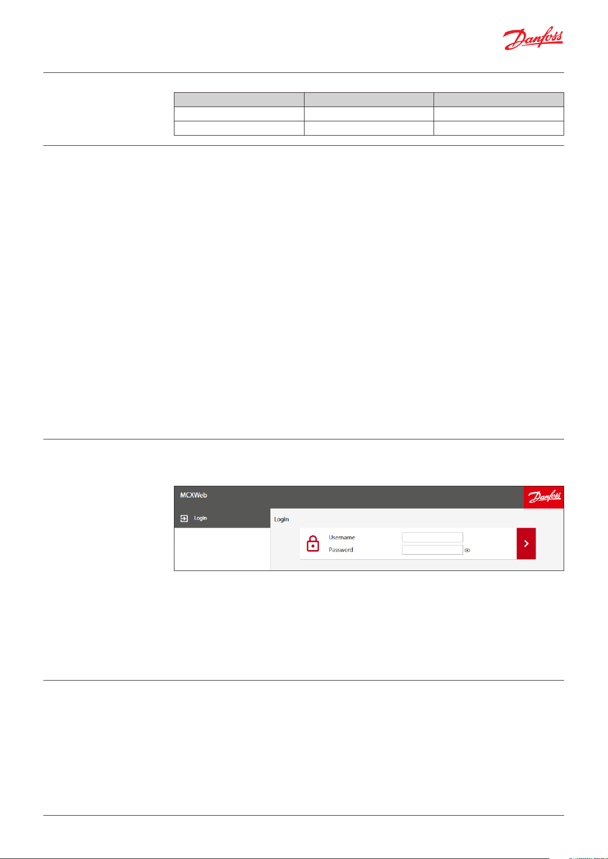
To login navigate with an HTML5 browser (e.g. Chrome) to the IP address of the gateway.
The screen will appear as follows:
Enter the username in the first box and the password in the second then press the right arrow.
The default credentials to access all configuration settings are:
• Username = admin
• Password = PASS
Password change is requested at first login.
Note: after each login attempt with wrong credentials a progressive delay is applied.
See 3.5 Users’ Configuration on how to create users.
The controller is provided with an HTML user interface that can be accessed with any browser.
By default, the device is configured for dynamic IP address (DHCP):
You can get the MCX15/20B2 IP address in several ways:
• Through USB. Within 10 minutes after power up, the device writes a file with configuration settings
into a USB flash drive, if present (see 7.1 Read current network configuration without web interface).
• Through the local display of MCX15/20B2 (in models where it is present). Press and release X+ENTER
immediately after power up to enter the BIOS menu. Then select GEN SETTINGS > TCP/IP.
• Through the software tool MCXWFinder, which you can download from the MCX website.
© Danfoss | DCS (vt) | 2021.01
BC337329499681en-000201 | 3
Page 4
User Guide | MCX15B2/MCX20B2, Programmable controller
Once connected for the first time, you can start to:
• configure the Web Interface. See 3.2 Settings
• configure the users. See 3.5 Users’ Configuration
• configure the main device MCX15/20B2 and any network of devices connected to the main
MCX15/20B2 through the fieldbus (CANbus). See 6. Install web pages updates.
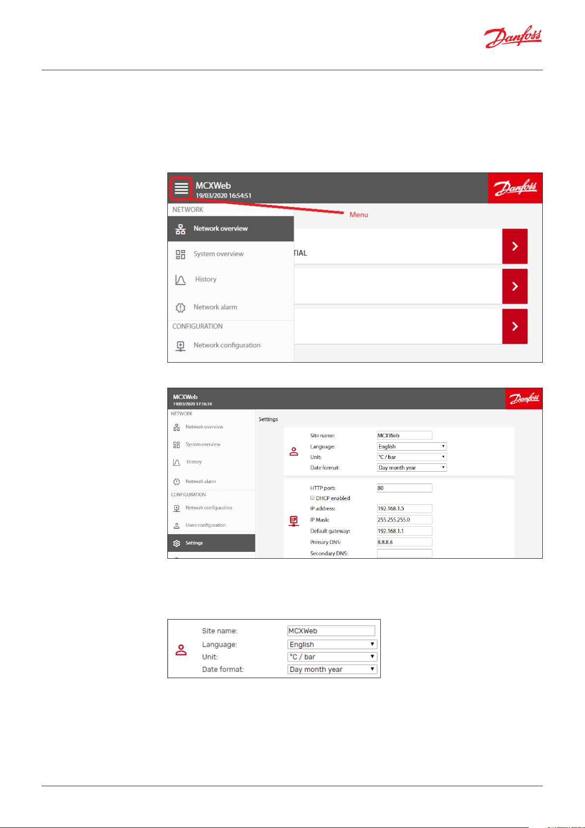
Note: the main menu is available in the left side of any page or can be displayed by clicking on the
menu symbol in the top left corner when it is not visible due to the page dimension:
3.2 Settings
3.2.1 Site name & localization
settings
To install updates, follow the instructions in 6. Install web pages updates.
The Settings menu is used to configure the Web Interface.
The Settings menu is visible only with the appropriate access level (Admin).
All the possible settings are described here below.
4 | BC337329499681en-000201
– Site name is used when alarms and warnings are notified with an email to the users (see 3.2.4 Email
notifications).
– Language of the Web Interface: English/Italian.
© Danfoss | DCS (vt) | 2021.01
Page 5
User Guide | MCX15B2/MCX20B2, Programmable controller
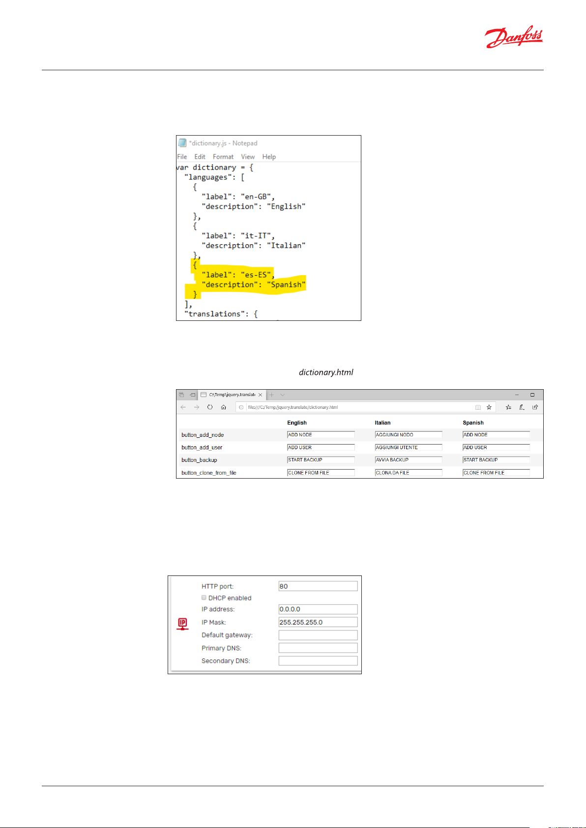
Further languages can be added following this procedure (for advanced users only):
• Copy the folder http\js\jquery.translate from the MCX to your computer via FTP
• Edit the dictionary.js file and add your language in the “languages” section of the file.
e.g. For Spanish, add the following two lines:
Note: you must use the languages code based on RFC 4646, which specifies a unique name for
each culture (e.g. es-ES for Spanish), if you want to retrieve the correct translation of the application
software data from the CDF file (see 3.3.3 Application and CDF).
3.2.2 Network Settings
• Using your browser, open the file and you will see an additional column with the
Spanish language
• Translate all the strings and press SAVE at the end. Strings that might be too long are highlighted in
red.
• Copy the new generated file dictionary.js into the MCX, in the http\js\jquery.translate folder
overwriting the previous one.
– Units of measurement used by the Web Interface: °C/bar or °F/psi
– Date format: Day month year or Month day year
© Danfoss | DCS (vt) | 2021.01
– HTTP port: You can change the default listening port (80) to any other value.
– DHCP: if DHCP is enabled by ticking the DHCP enabled box, the network settings (IP address, IP mask,
Default gateway, Primary DNS, and Secondary DNS) will be automatically assigned by the DHCP
server. Otherwise they must be manually configured.
BC337329499681en-000201 | 5
Page 6
User Guide | MCX15B2/MCX20B2, Programmable controller
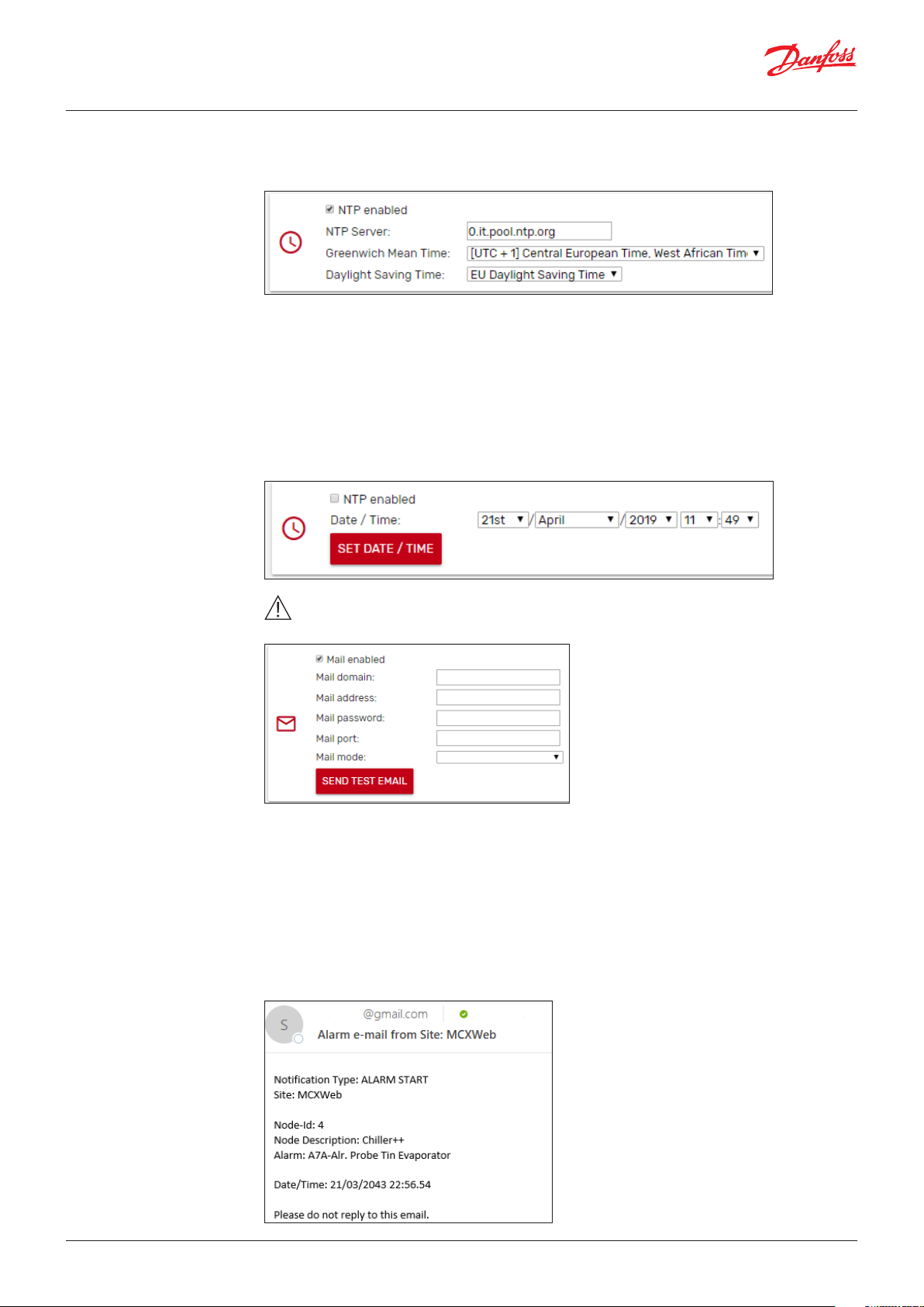
3.2.3 Date and Time acquisition
mode
The NTP protocol is used to automatically synchronize the time setting in the local controller.
By ticking the NTP enabled box, the Network Time Protocol is enabled, and the Date/Time is
automatically obtained from an NTP time server.
Set the NTP server you wish to synchronize with. If you don’t know the most convenient NTP server
URL of your region, use pool.ntp.org. The MCX15/20B2 real time clock will then be synchronized and
set according to the defined time zone and eventual daylight saving time.
Daylight Saving Time:
– OFF: deactivated
– ON: activated
– US: Start=Last Sunday of March – End=Last Sunday of October
– EU: Start=2nd Sunday of March – End=1st Sunday of November
If the NTP enabled box is not ticked, you can set the date and time of the MCX15/20B2 manually.
3.2.4 Email notifications
Warning: the time synchronization of the MCX controllers connected via fieldbus (CANbus) to
the MCXWeb is not automatic and must be implemented by the application software.
The device can be configured to send a notification via email when the status of the application alarm
changes.
Tick on Mail enabled to allow MCX15/20B2 to send an email after every change of the alarm status.
Mail domain is the name of the Simple Mail Transfer Protocol (SMTP) server that you want to use.
Mail address is the email address of the sender.
Mail password: password to authenticate with the SMTP server
For the Mail port and Mail mode refer to the configuration of the SMPT Server. Both unauthenticated
and SSL or TLS connections are managed. For each mode, the typical port is automatically proposed
but you can manually change it afterward.
Example of email sent by the device:
6 | BC337329499681en-000201
© Danfoss | DCS (vt) | 2021.01
Page 7
User Guide | MCX15B2/MCX20B2, Programmable controller
There are two types of notifications: ALARM START and ALARM STOP.
Send Test Email is used to send an email as a test to the Mail address above. Save your settings before
sending the test email.
The email destination is set when configuring the users (see 3.5 Users’ Configuration).
In case of mailing problems, you will receive one of the following error codes:
50 - FAIL LOADING CA ROOT CERTIFICATE
51 - FAIL LOADING CLIENT CERTIFICATE
52 - FAIL PARSING KEY
53 - FAIL CONNECTING SERVER
54 -> 57 - FAIL SSL
58 - FAIL HANDSHAKE
59 - FAIL GET HEADER FROM SERVER
60 - FAIL EHLO
61 - FAIL START TLS
62 - FAIL AUTHENTICATION
63 - FAIL SENDING
64 - FAIL GENERIC
Note: do not use private email accounts to send emails from the device as it has not been designed to
be GDPR compliant.
3.2.4.1 Gmail configuration
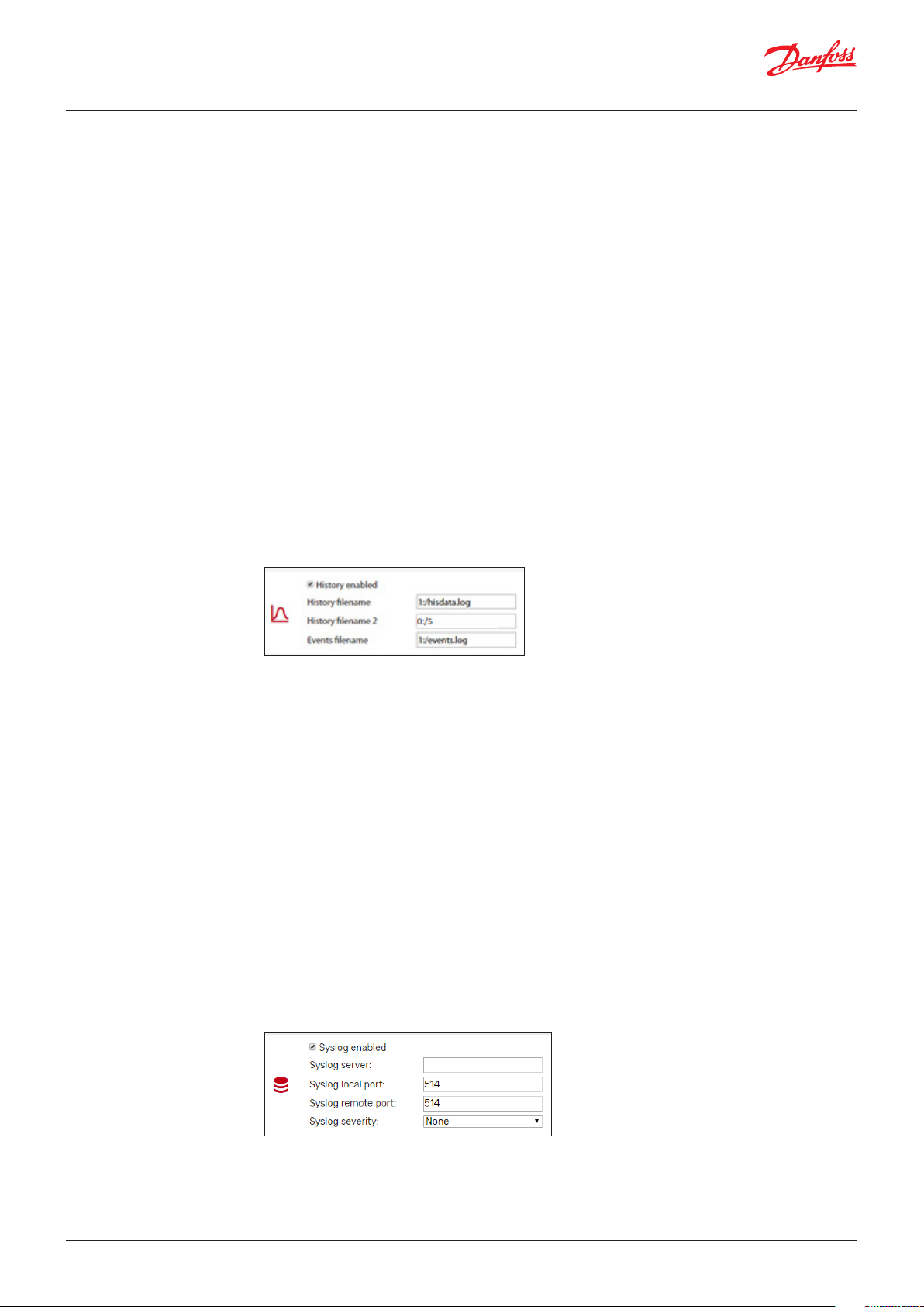
3.2.5 History
3.2.6 System Overview
3.2.7 FTP
3.2.8 Modbus TCP
Gmail may require you to enable access to less secure apps in order to send emails from embedded
systems.
You can enable this feature here: https://myaccount.google.com/lesssecureapps.
Specify the name and position of the datalog files as defined by the MCX application software.
If the name starts with 0: the file is saved in the internal MCX15/20B2 memory. In the internal memory
it is possible to have max. one datalog file for variables and the name must be 0:/5.
If the name starts with 1: the file is saved in the USB flash drive connected to the MCX15/20B2.
In the external memory (USB flash drive), it is possible to have one file for logging variables (the name
must be 1:/hisdata.log) and one for events like alarm start and stop (the name must be 1:/events.log)
See 4.3 History for a description on how to view historical data.
Tick on System Overview enabled to create a page with the overview of the main system data including
those coming from all devices connected to the main controller’s FTP communication (see 5.1.2
Creation of a Customized System Overview page).
Tick on FTP enabled to allow FTP communication.
FTP communication is not secure, and it is not recommended that you enable it. It can be useful if you
need to upgrade the web interface however (see 6. Install web pages updates)
Tick on Modbus TCP Slave enabled to enable Modbus TCP slave protocol, connecting over port 502.
Note that the COM3 communication port must be managed by the application software on the MCX
to have the Modbus TCP protocol working.
In MCXDesign applications, the brick ModbusSlaveCOM3 must be used and in the InitDefines.c file in
the App folder of your project the instruction #define ENABLE_MODBUS_SLAVE_COM3 must be present
in the right position (see the help of the brick).
3.2.9 Syslog
© Danfoss | DCS (vt) | 2021.01
Tick on Syslog enabled to enable Syslog protocol. Syslog is a way for network devices to send event
messages to a logging server for diagnostic and troubleshooting purposes.
Specifies the IP address and port for connections to the server.
Specifies the kind of messages, by severity level, to be sent to the syslog server.
BC337329499681en-000201 | 7
Page 8
User Guide | MCX15B2/MCX20B2, Programmable controller
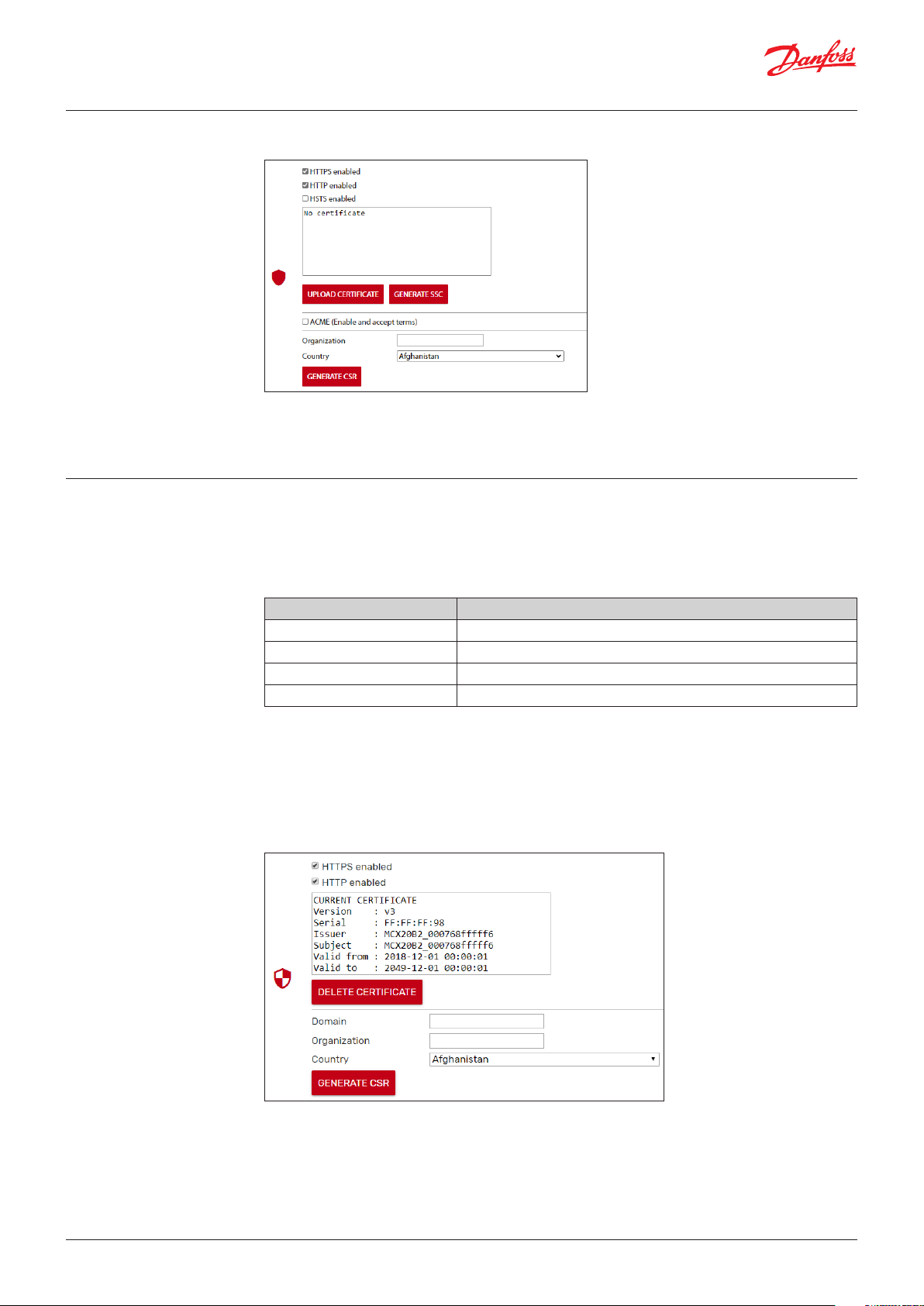
3.2.10 Security
3.2.10.1 Certificates
See 8. Security for further information on MCX15/20B2 security.
Enable HTTPS with personalized server certificate if the device is not in a secure environment.
Enable HTTP if the device is in a secure LAN with authorized access available (also VPN).
Enable HSTS if you want to force web browsers to interact with the device only via secure HTTPS
connections (and never HTTP). This helps to prevent protocol downgrade attacks.
A dedicated certificate is needed to access the webserver over HTTPS.
The certificate management is the responsibility of the user. In order to generate a certificate, it is
necessary to follow the steps below.
Creating a self-signed certificate
• Click GENERATE SSC to generate a self-signed certificate
PROs of Self-Signed Certificates CONs
Immediate availability Does not protect against Man In The Middle (no authentication with PKI)
Rises alerts in browsers
Supported by few browsers
Support could cease
Creating and assigning a CA-signed certificate
• Fill in the requested data about Domain, Organization, and Country
• Click GENERATE CSR to generate a Private key and Public key pair and a Certificate Sign Request
(CSR) in PEM and DER format
• The CSR can be downloaded and sent to Certification Authority (CA), public or other, to be signed
• The signed certificate can be uploaded into the control clicking the UPLOAD CERTIFICATE. Once
completed the certificate information is shown in the text box, see the example below:
8 | BC337329499681en-000201
© Danfoss | DCS (vt) | 2021.01
Page 9

User Guide | MCX15B2/MCX20B2, Programmable controller
PROs of CA-Signed Certificates CONs
Higher security Complex process
Supported by browsers CA certificate must be installed on client devices
Automatic Certificate Management
An automatic management system takes care of issuing and updating the certificate
• You need a normal router and DDNS service. Open port 443, port 80
• Tick on ACME to enable the Automatic Certification Management
• Fill in the requested data about Domain, and Email
After few minutes, if the device is connected to the Internet, you should see some messages
appearing in the text box as in the picture below.
At the end you will have a certificate installed in your device, signed by an ACME enabled Certification
Authority. At the present stage, MCX15/20B2 relies on Let’s Encrypt Certification Authority.
Certificates must be renewed manually
Could have costs
PROs of ACME CONs
High security
Immediate availability
Supported by Browsers
Set and forget
© Danfoss | DCS (vt) | 2021.01
BC337329499681en-000201 | 9
Page 10

User Guide | MCX15B2/MCX20B2, Programmable controller
3.3 Network Configuration
3.3.1 Node ID
In this page, you configure which devices you want to access through the MCX Web interface.
Press ADD NODE to configure each device of your network.
Press SAVE to save the changes.
After the configuration, the device is shown in the Network Overview page.
Select the ID (CANbus address) of the node that will be added.
The devices which are physically connected to the network are automatically displayed in the
dropdown list of Node Id.
3.3.2 Description
3.3.3 Application and CDF
You can also add a device which is not connected yet, selecting the ID that it will have.
For each device in the list you can specify a description (free text) that will be displayed in the Network
overview page.
For each device in the list you must specify the application description file (CDF).
The application description file is a file with CDF extension containing the description of variables and
parameters of the software application running in the MCX device.
CDF must be 1) created 2) loaded 3) associated.
1. Create the CDF with MCXShape
Before creating the CDF, use MCXShape tool to configure the MCX software application according
to your needs.
The CDF file of the MCX software application has the CDF extension and it is created during the
“Generate and Compile” procedure by MCXShape.
The CDF file is saved in the folder App\ADAP-KOOL\edf of the software application.
It is required MCXShape v4.02 or higher.
2. Load the CDF
Load the CDF in the MCX15/20B2 as described in 3.4 Files
3. Associate the CDF
Finally, the CDF must be associated to the device through the combo menu in the Application field.
This combo is populated with all the CDF files created with the MCXShape and loaded into the
MCX15/20B2.
Note: when you change a CDF file that was already associated to a device, a red star appears aside
of the Network configuration menu and you get the following warning message in the Network
configuration page: CDF MODIFIED, PLEASE CONFIRM THE CONFIGURATION. Press over it to confirm the
change after checking the Network configuration.
10 | BC337329499681en-000201
© Danfoss | DCS (vt) | 2021.01
Page 11

User Guide | MCX15B2/MCX20B2, Programmable controller
3.3.4 Alarm mail
3.4 Files
Tick on Alarm mail to allow email notification from the device.
Email target is set in Users’ configuration (see 3.5 Users’ Configuration).
The email account of the sender is set in Settings (see 3.2.4 Email notifications)
Below shows an example of an email sent by a device. The Date/Time of the alarm start or stop is when
the webserver recognizes that event: this may be different from when it occurred, for example after a
power off, the Date/Time will be the power on time.
This is the page used to load any file into the MCX15/20B2 related to the MCX15/20B2 itself and to the
other MCX connected to it. Typical files are:
• Application software
• BIOS
• CDF
• Pictures for the overview pages
© Danfoss | DCS (vt) | 2021.01
BC337329499681en-000201 | 11
Page 12

User Guide | MCX15B2/MCX20B2, Programmable controller
Press UPLOAD and select the file that you want to load into the MCX15/20B2.
Example of CDF file
3.5 Users’ Configuration This is the list of all the users that can access the Web interface. Click on ADD USER to add a new user or
on “-“to delete it.
There are 4 possible levels of access: guest (0), maintenance (1), service (2), and admin (3). These levels
correspond to the levels assigned in the CDF by the MCXShape tool.
Each level has associated specific permissions:
Permissions Admin (3) Service (2) Maintenance (1) Guest (0)
Parameter settings
Modify overview page
Alarms
Runtime chart
Backup / Copy / Clone
Upgrade
Device info
Network overview
History
Network alarms
Network configuration
User configuration
Settings
Diagnostic
Files
Info
12 | BC337329499681en-000201
Note: you can see only the users with the level equal or lower than the one you are logged in with.
Select the Alarm Notification check box to send notification emails to the user when alarms occur in
any device in the CANbus network enabled to send email (see 3.3 Network Configuration).
The target address for emails is defined in the Mail field of the user.
See also 3.2.4 Email notifications, on how to set the SMTP mail server.
The password must be at least 10 characters in length.
© Danfoss | DCS (vt) | 2021.01
Page 13

User Guide | MCX15B2/MCX20B2, Programmable controller
3.6 Diagnostic
This section is useful for verifying your network configuration and seeing which protocols are active
and whether the corresponding destinations are reachable, if relevant. In addition, a System log is
displayed where events of major importance concerning security are recorded.
3.7 Info
This page displays the following information relating to the current MCX15/20B2 device:
Id: address in the CANbus network
Site version: version of the web interface
BIOS version: version of the MCX15/20B2 firmware
Serial number of MCX15/20B2
Mac address of MCX15/20B2
Further Info: license information
3.8 Logout
© Danfoss | DCS (vt) | 2021.01
Select this to log out.
BC337329499681en-000201 | 13
Page 14
User Guide | MCX15B2/MCX20B2, Programmable controller
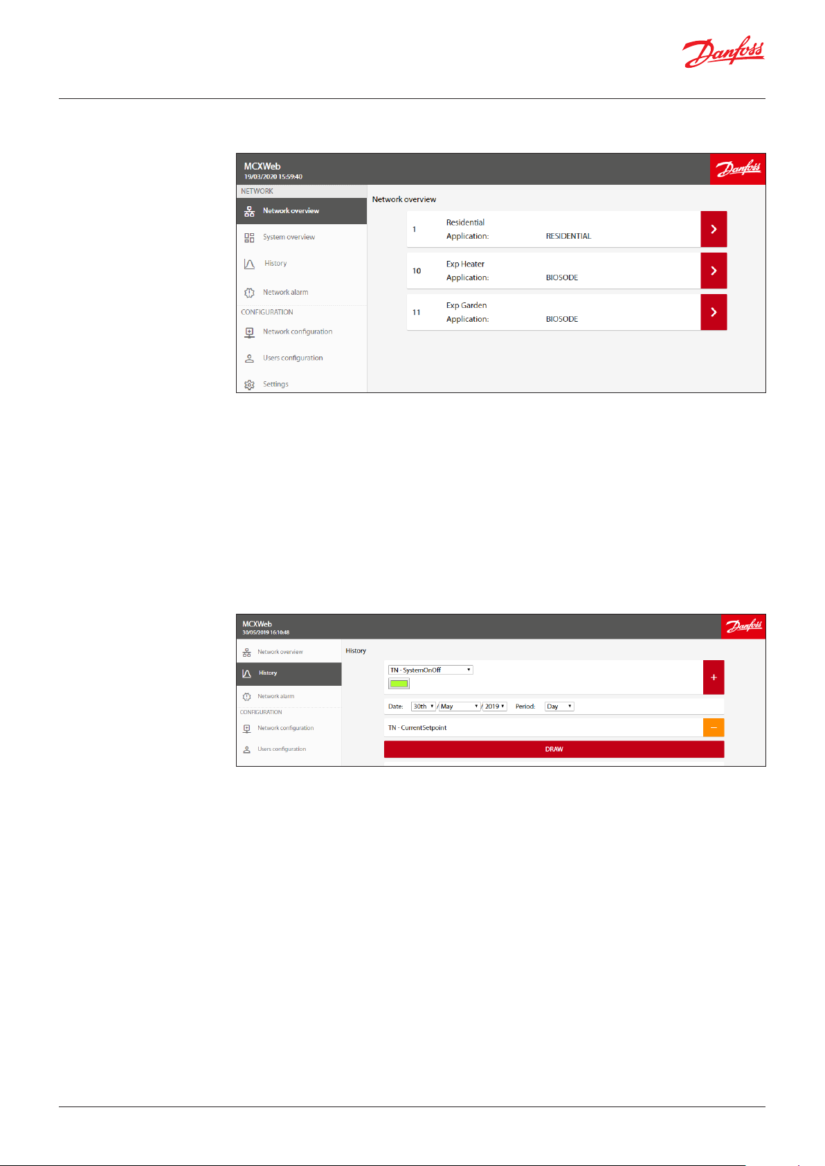
4. Network
4.1 Network overview
The Network overview is used to list the main controller MCX15/20B2 and all the devices configured in
the Network Configuration and connected to the main controller through fieldbus (CANbus).
For each configured MCX the following information is displayed:
• Node ID, which is the CANbus address of the device
•
Device Name (e.g. Residential), which is the name of the device. This is defined in Network Configuration
• Application, this is the name of the application software running in the device (e.g. RESIDENTIAL).
The application is defined in Network Configuration.
• Communication status. If the device is configured but not connected, a question mark is shown on
the right side of the device line. If the device is active, a right arrow is displayed
If you click over the right arrow of the line with the device you are interested in, you will enter the
device specific pages (see 5. Device Pages).
4.2 System overview
4.3 History
See 5.1.2 Creation of a Customized System Overview page.
The History page will show the historical data stored in the MCX15-20B2, if the application software on
the MCX has been developed to store them.
Note:
• Your application on the MCX must use the software library LogLibrary v1.04 and MCXDesign v4.02 or
greater.
• History must be enabled in Settings (see 3.2.5 History).
Each MCX software application defines the set of variables that are logged. The drop-down list only
shows the variables that are available.
If you can’t see any variables, check that the name of the history file in Settings is correct and
corresponds to the name used by the application software (see 3.2.5 History).
Select the variable you want to view, the colour of the line in the graph, and set the date/time interval.
Press “+“to add the variable and “-“ to remove it.
14 | BC337329499681en-000201
© Danfoss | DCS (vt) | 2021.01
Page 15

User Guide | MCX15B2/MCX20B2, Programmable controller
Then press DRAW to view the data.
Use your mouse to zoom in on your graph by using the click+drag option.
This feature is not available on the mobile version of the pages.
Press the camera icon to take a snapshot of the chart.
Press the File icon to export displayed data in CSV format. In the first column you have the time stamp
of points in Unix Epoch time, that is the number of seconds that have elapsed since 00:00:00 Thursday,
1 January 1970.
Note that you can use Excel formulas to convert the Unix time, e.g.
=((((LEFT(A2;10) & “,” & RIGHT(A2;3))/60)/60)/24)+DATE(1970;1;1) where A2 is the cell with the Unix time.
The cell with the formula should then be formatted as dd/mm/yyyy hh:mm:ss or similar.
© Danfoss | DCS (vt) | 2021.01
BC337329499681en-000201 | 15
Page 16

User Guide | MCX15B2/MCX20B2, Programmable controller
4.4 Network Alarm
16 | BC337329499681en-000201
This page shows the list of the alarms active for all the devices connected to the fieldbus (CANbus).
Alarms for each individual device are also available on the device pages.
© Danfoss | DCS (vt) | 2021.01
Page 17

User Guide | MCX15B2/MCX20B2, Programmable controller
5. Device Pages
From the Network overview page, if you click over the right arrow of a specific device you will enter
the device specific pages.
The fieldbus address and node description of the selected device are shown at the top of the menu:
5.1 Overview
5.1.1 Customization of the
Overview page
The overview page is typically used to show the main application data.
By pressing the Favourite icon on the left side of a variable, you make it automatically visible in the
Overview page.
Pressing the Gear icon in the Overview page, you can customize it further using a predefined format.
© Danfoss | DCS (vt) | 2021.01
BC337329499681en-000201 | 17
Page 18

User Guide | MCX15B2/MCX20B2, Programmable controller
The format is as follows:
Example of Customized Overview page Predefined sections
Main parameter
(1 maximum)
Additional parameters
(8 maximum)
Run time chart
(7 maximum)
Editable parameters
Custom view
Custom image with
parameter values
The Editable Parameters are those selected by pressing the Favourite icon on the left side of a variable
(see 5.1 Overview).
You can add or remove new parameters to this list from this Overview configuration page.
The Custom View is the section where you define which image you want to display in the Overview
and what the data is for the values you want to show over the picture.
18 | BC337329499681en-000201
© Danfoss | DCS (vt) | 2021.01
Page 19

User Guide | MCX15B2/MCX20B2, Programmable controller
To create a Custom view, follow these steps:
1. Load an image, e.g. VZHMap4.png in the figure above
2. Select a variable to display over the image, e.g. the input Tin Evaporator
3. Drag and drop the variable over the image in the desired position. Drag and drop it outside the
page to remove it
4. Right click over the variable to change the way it will be displayed. The following panel will appear:
If you select the Type=On/Off Image:
5.1.2 Creation of a Customized
System Overview page
the Image on and Image off fields can be used to associate different images to the ON and OFF value of
a Boolean variable. A typical usage is to have different icons for the alarm ON and OFF states. The On/
Off images must have been loaded previously through the Files menu (see 3.4 Files).
A System Overview page is a page that collects data from different devices in the network.
If you follow the instructions below you can create a System Overview page and display data over a
picture of the system.
• In Settings, tick on System Overview enabled to enable the System Overview page. In the Network
section of the menu the line System Overview will appear.
© Danfoss | DCS (vt) | 2021.01
• Press the Gear icon in the System Overview page to customize it.
• Select the node in the network from which you want to select the data and then follow the steps 1-4
described in 5.1.1 Customization of the Overview page.
BC337329499681en-000201 | 19
Page 20

User Guide | MCX15B2/MCX20B2, Programmable controller
5.2 Parameter settings On this page you have access to the different parameters, virtual input/output (I/O functions) values
and main commands by navigating the menu tree.
The menu tree for the application is defined with MCXShape.
When the parameters are displayed, you can check the current value and the unit of measurement for
each of them.
To change the current value of a writable parameter, click on the down arrow.
Edit the new value and click outside the text field to confirm.
Note: Min. and max. value are monitored.
To move through the parameter tree, you can click on the desired branch at the top of the page.
20 | BC337329499681en-000201
© Danfoss | DCS (vt) | 2021.01
Page 21

User Guide | MCX15B2/MCX20B2, Programmable controller
5.3 Alarms
5.4 Physical I/O
5.5 Runtime chart
On this page are all the alarms active in the device.
On this page are all the physical inputs/outputs.
On this page you can select the variables to populate the real-time graph.
Navigate the menu tree and select the variable you want to graph. Press “+”to add it and “-“ to delete it.
In the X axis of the graph is the number of points or samples.
The period to display in the graph window is defined by Refresh time x Number of points.
5.6 Copy/Clone
5.6.1 Backup
Press the camera icon to take a snapshot of the chart.
Press the File icon to export displayed data in CSV format. In the first column you have the time stamp of
points in Unix Epoch time, that is the number of seconds that have elapsed since 00:00:00 on Thursday,
1 January 1970.
Note that you can use Excel formulas to convert the Unix time, e.g.
=((((LEFT(A2;10) & “,” & RIGHT(A2;3))/60)/60)/24)+DATE(1970;1;1) where A2is the cell with the Unix time.
The cell with the formula should then be formatted as dd/mm/yyyy hh:mm:ss or similar.
This page is used to save and restore the current value of parameters. It allows you to make a back-up
of your configuration and to replicate, if necessary, the same configuration or a subset of it in a different
device when the same software application is running.
The selection of parameters to be backed up and restored is made when you configure your MCX application
through the MCXShape configuration tool. In MCXShape, when the Developer mode is enabled, there is
a column “Copy Type” with three possible values:
• Don’t Copy: identifies parameters which you do not want to save in the backup file (e.g. Read Only
parameters)
• Copy: identifies parameters that you want to save in the backup file and that can be restored with
the Copy and the Clone functionalities in the web interface (see 5.6.2 Copy from File)
• Clone: identifies parameters that you want to save in the backup file and that will be restored only
with the Clone functionality in the web interface (see 5.6.3 Clone from file) and that will be skipped
by the Copy functionality (e.g. CANbus ID, baudrate, etc).
When you press on START BACKUP, all the parameters with the attributes Copy or Clone in the column
Copy Type of MCXShape configuration tool will be saved into the file BACKUP_ID_Applicationname
in your Download folder, where ID is the address in the CANbus network and Applicationname is the
name of the application running in the device.
5.6.2 Copy from File
5.6.3 Clone from file
© Danfoss | DCS (vt) | 2021.01
The Copy function allows you to copy some of the parameters (those marked with the attribute Copy
in the column Copy Type of MCXShape configuration tool) from the backup file to the MCX controller.
Parameters marked with Clone are excluded from this type of copy.
The Clone function allows you to copy all the parameters (marked with the attribute Copy or Clone in
the column Copy Type of MCXShape configuration tool) from the backup file to the MCX controller.
BC337329499681en-000201 | 21
Page 22

User Guide | MCX15B2/MCX20B2, Programmable controller
5.7 Upgrade
5.7.1 Application Upgrade
This page is used to upgrade the applications (software) and BIOS (firmware) from remote.
The target controller can be both the MCX15-20B2 device or other controllers connected through the
fieldbus (CANbus), where the upgrade progress is shown in the upgrade tab.
To proceed with the application and/or BIOS update, follow these steps:
• Copy the software application file, created with the MCXShape with the pk extension, into the
MCX15/20B2 as described in 3.4 Files.
• On the Upgrade page, select from the Application combo menu the application you wish to upgrade
on the device from all the pk files you have loaded.
• Confirm the update by pressing the upgrade icon (up arrow).
It is recommended that you power off the device after the upgrade.
5.7.2 BIOS Upgrade
5.8 Device Info
After the application upgrade, also remember to upgrade the related CDF file (see 3.4 Files) and the
Network configuration (see 3.3.3 Application and CDF).
Note: applications can also be upgraded via USB, see 7.2.1 Install application upgrades from USB flash
drive.
Copy the BIOS file, with the bin extension, into the MCX15/20B2 as described in 3.4 Files.
Note: do not change the file name of the BIOS or it will not be accepted by the device.
On the Upgrade page, select from the Bios combo menu the BIOS you wish to upgrade on the device
from all the BIOS files you have loaded.
Confirm the update by pressing the upgrade icon (up arrow).
If you have selected the appropriated BIOS (bin file) for the current MCX model, then the BIOS update
procedure will start.
Note: if the BIOS of the MCX you are connected to the web interface with is upgraded, you will need
to log into the web interface again once the device has completed the reboot.
Note: The BIOS can also be upgraded via the USB, see 7.2.2 Install BIOS upgrades from USB flash drive.
22 | BC337329499681en-000201
On this page the main information relating to the current device is displayed.
© Danfoss | DCS (vt) | 2021.01
Page 23

User Guide | MCX15B2/MCX20B2, Programmable controller
6. Install web pages
updates
New web pages can be updated via FTP, if enabled (see 3.2.7 FTP):
The web pages package is made by files grouped in four folders which must replace the ones in the
MCX15/20B2.
To update the pages, it is enough to overwrite the HTTP folder, as the others will be created
automatically.
Notes:
• It is recommended that you stop running the application on MCX15/20B2 before starting the FTP
communication. To do this, press and release X+ENTER immediately after power up to enter the
BIOS menu. At the end of the FTP communication, select APPLICATION from the BIOS menu to start
the application again.
• After the upgrade of the web pages, it is mandatory to clean the cache of your browser (e.g. with
CTRL+F5 for Google Chrome).
© Danfoss | DCS (vt) | 2021.01
BC337329499681en-000201 | 23
Page 24

User Guide | MCX15B2/MCX20B2, Programmable controller
7. USB
7.1 Read current network
configuration without
web interface
7.2 BIOS and Application
upgrade
7.2.1 Install application
upgrades from USB flash
drive
If you can’t access the web interface, you can still read the network configuration using a USB flash
drive:
• Make sure the USB flash drive is formatted as FAT or FAT32.
• Within 10 minutes of MCX15/20B2 powering up, insert the USB flash drive into the USB connector of
the device.
• Wait about 5 seconds.
• Remove the USB flash drive and insert into a PC. The file mcx20b2.cmd will contain the basic
information about the product.
Here is an example of the content:
[node_info]
ip=10.10.10.45/24
mac_address=00:07:68:::f6
sw_descr=MCX20B2 0c41
node_id=1
CANBaud=50000
Key=bsFJt3VWi9SDoMgz
< - Current ip address
< - Mac address
< - Bios software description
< - CANbus Node ID
< - CANbus baudrate
< - Temporary key generated at le
creation
A USB flash drive can be used to upgrade the BIOS and application of MCX15-20B2.
Both can also be upgraded via web pages, see 5.7 Upgrade.
To update the MCX15-20B2 application from a USB flash drive:
• Make sure the USB flash drive is formatted as FAT or FAT32.
• Save the firmware in a file named app.pk in the root folder of the USB flash drive.
• Insert the USB flash drive into the USB connector of the device; turn it off and on again and wait a
few minutes for the update.
Note: do not change the file name of the application (it must be app.pk) or it will not be accepted by
the device.
7.2.2 Install BIOS upgrades
from USB flash drive
7.3 Emergency actions
through USB
To update the MCX15-20B2 BIOS from USB flash drive:
• Make sure the USB flash drive is formatted as FAT or FAT32.
• Save the BIOS in the root folder of the USB flash drive.
• Insert the USB flash drive into the USB connector of the device; turn it off and on again and wait a
few minutes for the update.
Note: do not change the file name of the BIOS or it will not be accepted by the device.
It is possible to recover the unit in case of emergency situations by providing some commands
through the USB.
These instructions are for expert users and assume familiarity with INI file format.
The available commands allow the user to perform the following operations:
• Reset the network settings
• Reset the user configuration to default
• Format the partition that contains pages and configurations
Procedure
• Follow instructions in 7.1 Read current network configuration without web interface to generate the
file mcx20b2.cmd.
• Open the file with a text editor and add the following lines to perform special operations as
described in the table below.
Command Function
ResetNetworkConfig=1 Reset the network settings:
• DHCCP enabled
• FTP enabled
• HTTPS disabled
ResetUsers=1 Reset the user configuration to default:
• User=admin
• Password=PASS
Format Format the partition containing web pages and configurations
• Insert the USB flash drive back into the MCX15/20B2 to execute the commands
24 | BC337329499681en-000201
© Danfoss | DCS (vt) | 2021.01
Page 25

User Guide | MCX15B2/MCX20B2, Programmable controller
Example:
[node_info]
ip=10.10.10.45/24
mac_address=00:07:68:::f6
sw_descr=MCX20B2 0c41
node_id=1
CANBaud=50000
Key=bsFJt3VWi9SDoMgz
ResetNetworkCong=1
This will reset the network settings.
Note: the commands will not be re-executed if you remove and insert the USB flash drive again. The
Key line in the node-info section is ensuring this. To execute new commands, you must delete the
mcx20b2.cmd file and re-generate it.
7.4 Datalogging
8. Security
8.1 Security architecture
8.1.1 Foundation
8.1.2 Core
A USB flash drive can be used to store historical data, see 4.2 History.
Security information
MCX15/20B2 is a product with functions that support the security in operation of machines, systems
and networks.
Customers are responsible for preventing unauthorized access to their machines, systems and
networks. These must be connected to a corporate network only or to the Internet if and to the
extent that such connection is necessary and only when appropriate security measures are in place
(e.g. firewall). Contact your IT department to ensure that the device is installed according to your
company’s security policies.
MCX15/20B2 is continuously developed to make it safer, therefore is recommended that you apply
product updates as they become available and use the latest product versions. Use of product
versions that are no longer supported and failure to apply the latest updates may increase customers’
exposure to cyber threats.
MCX15/20B2 architecture for security is based on elements that can be grouped in three main
building blocks:
• foundation
• core
• monitoring and threats
The foundation is the part of hardware and basic low-level drivers that ensure access restriction at HW
level, that the device is operated with a genuine Danfoss software and includes the basic building
blocks needed by the core components.
The core building blocks are the central part of the security infrastructure. It includes the support for
cipher suites, protocols, user and authorization management.
8.1.2.1 Authorization
8.1.2.2 Policies
8.1.2.3 Secure Update
© Danfoss | DCS (vt) | 2021.01
• User Management
• Access control to configuration
• Access control to application/machine parameters
• Strong password enforcement:
• A change of the default password is enforced on first access. This is mandatory as it would be a
major security leak.
• In addition, a strong password is enforced according to minimum requirements policy: at least 10
characters.
• Users are managed only by the administrator
• User passwords are stored with cryptographic hash
• Private keys are never exposed
The update manager software library verifies that the new firmware has a valid digital signature before
starting the update process.
• Cryptographic Digital Signature
• Firmware roll-back guaranteed if not valid
BC337329499681en-000201 | 25
Page 26

8.1.2.4 Factory Configuration
From the factory, the web interface will be accessible without security.
• HTTP, FTP (disabled by default)
• 1st access administrator password selection with strong password is required
8.1.2.5 Certificates
8.1.2.6 Reset Default Settings
and Recovery
8.1.3 Monitoring
8.1.3.1 Response
8.1.3.2 Log and email
A dedicated certificate is needed to access the web server over HTTPS.
The certificate management including any updates is the responsibility of the customer.
The Reset to default parameters is available through a special command with the USB port. Physical
access to the device is considered to be an authorized access. As such the reset of network settings or
reset of user passwords can be executed without further restrictions.
Track, inform and respond to security threats.
There are some response strategies implemented to mitigate the risk of brute force cyber-attack.
This kind of attack can work on different levels:
• on the login API, thus trying continuously different credentials for access
• using different session tokens
In the first instance, progressive delays are implemented to mitigate the risk, whilst for the second one
a warning email is sent out and a log entry is written.
To keep track and inform the user/IT about threats the following services are available:
• Log of security related events
• Reporting of events (email to the administrator)
Events relevant for security are:
• Too many attempts to login with wrong credentials
• Too many requests with wrong session ID
• Changes to account settings (password)
• Changes to security settings
© Danfoss | DCS (vt) | 2021.01 BC337329499681en-000201 | 26
ADAP-KOOL®
 Loading...