

Installation Guide
Electronic controller
080R9340
MCX15B2/20B2
General features:
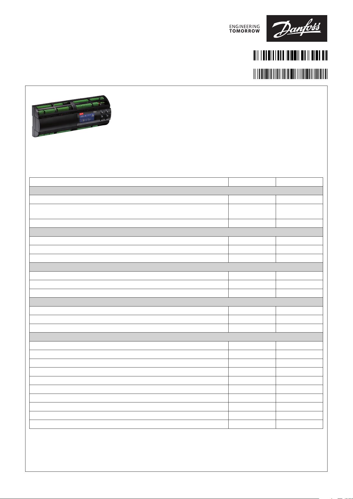
MCX15B2/MCX20B2 is an electronic controller that stands on the top of the MCX range,
thanks to the large number of its inputs and outputs, the enhanced CPU capabilities and
connectivity features.
It holds all the typical functionalities of MCX controllers: programmability, connection to the
CANbus local network, up to two Modbus RS485 serial interfaces with galvanic isolation.
Furthermore, it is fitted with an ultra wide range (24/110/230 V AC) power supply in the
same product variant, with USB and Ethernet connection for embedded Web server and IP
protocols management.
It is available in several models, with or without graphic LCD display and with 15 or 20 digital
output.
MC X15B2 MCX20B2
ANALOG INPUTS
NTC, 0/1 V, 0/5 V, 0 / 10 V PT1000, selectable via software 4 6
Universal NTC, Pt1000, 0/1 V, 0/5 V, 0/10 V, ON/OFF, 0/20 mA, 4/20 mA, selectable via
software
Total number 10 16
DIGITAL INPUTS
Voltage free contact/24V AC sensing 18 18
24/230 V AC optoinsulated 4 4
Total number 22 22
ANALOG OUTPUTS
0/10 V DC optoinsulated 6 6
0/10 V, PWM, PPM selectable via software 2 2
Total number 6 6
DIGITAL OUTPUTS
SPDT relay 16 A (changeover contacts) 2 2
SPST relay 5 A (normally open contacts) 13 18
Total number 15 20
OTHERS
Power supply 24-110-230 V AC / 40-230 V DC • •
Connection for programming key and for remote display and keyboard • •
Buzzer - RTC clock • •
Modbus RS485 serial interface x1 x2
CANbus • •
Ethernet for Webserver/Modbus TCP • •
USB for firmware/application software update and datalogging • •
Dimensions (DIN modules) 16 16
Mounting DIN rail DIN rail
AN320819413085en-000401
6 10
© Danfoss | DCS (vt) | 2020.10
AN320819413085en-000401 | 1

General features and warnings
Plastic housing features
• DIN rail mounting complying with EN 60715
• Self extinguishing V0 according to IEC 60695-11-10 and glowing/hot wire test at 960 °C according to IEC 60695-2-12
• Ball test: 125 °C according to IEC 60730-1. Leakage current: ≥ 250 V according to IEC 60112
Other features
• Operating conditions CE: -20T60 / UL: 0T50, 90% RH non-condensing
• Storage conditions: -30T80, 90% RH non-condensing
• To be integrated in Class I and/or II appliances
• Index of protection: IP40 only on the front cover
• Period of electric stress across insulating parts: long
• Suitable for use in environments with degree of pollution 2
• Category of resistance to heat and fire: D
• Immunity against voltage surges: category II, category III for versions without display
• Software class and structure: class A
Compliance
CE mark
This product is designed to comply with the following EU standards:
• Low voltage directive LVD 2014/35/EU:
– EN60730-1: 2011 (Automatic electrical control for household and similar use. General requirements)
– EN60730-2-9: 2010 (Particular Requirements for Temperature Sensing Controls)
• Electromagnetic compatibility EMC directive 2014/30/EU:
– EN 61000-6-3: 2007 +A1: 2011 (Emission standard for residential, commercial and light-industrial environments)
– EN 61000-6-2: 2005 (Immunity for industrial environments)
• RoHS directive 2011/65/EU and 2015/863/EU:
– EN50581: 2012
UL approval:
• UL file E31024
General warnings
• Every use that is not described in this manual is considered incorrect and is not authorised by the manufacturer
• Verify that the installation and operating conditions of the device respect the ones specified in the manual, specially concerning the
supply voltage and environmental conditions
• This device contains live electrical components therefore all the service and maintenance operations must be performed by qualified
personnel
• The device can’t be used as a safety device
• Liability for injury or damage caused by the incorrect use of the device lies solely with the user
Installation warnings
• Mounting position recommended: vertical
• The installation must be executed according the local standards and legislations of the country
• Always operate on the electrical connections with the device disconnected from the main power supply
• Before carrying out any maintenance operations on the device, disconnect all the electrical connections
• For safety reasons the appliance must be fitted inside an electrical panel with no live parts accessible
• Don’t expose the device to continuous water sprays or to relative humidity greater than 90%.
Avoid exposure to corrosive or pollutant gases, natural elements, environments where explosives or mixes of flammable gases are
present, dust, strong vibrations or shock, large and rapid fluctuations in ambient temperature that in combination with high humidity
can condensate, strong magnetic and/or radio interference (e.g. transmitting antennae)
• When connecting loads beware of the maximum current for each relay and connector
• Use cable ends suitable for the corresponding connectors. After tightening the screws of connectors, slightly tug the cables to check
their tightness
• Use appropriate data communication cables. Refer to the Installation Guide “MCX hardware network specification” for the kind of cable
to be used and setup recommendations
• Reduce the path of the probe and digital inputs cables as much as possible, and avoid spiral paths enclosing power devices. Separate
from inductive loads and power cables to avoid possible electromagnetic noises
• Avoid touching or nearly touching the electronic components fitted on the board to avoid electrostatic discharges
• The product is not suitable to be exposed directly to the Internet
2 | AN320819413085en-000401
© Danfoss | DCS (vt) | 2020.10
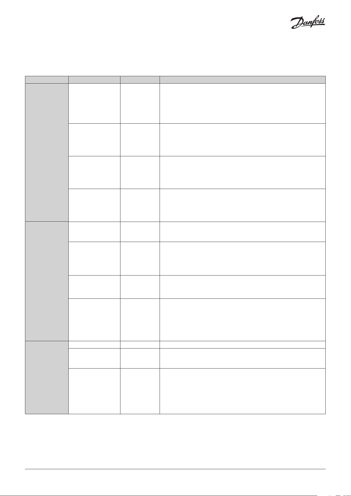
Technical specifications
Power supply
• 21 – 265 V AC, 50/60 Hz. Maximum power consumption: 15 W. Insulation between power supply and the extra-low voltage: reinforced
• 40 – 230 V DC
I/O TYPE NUM SPECIFICATIONS
Analog
inputs
Digital
inputs
NTC
0 / 1 V
0 / 5 V
0 / 10 V
PT1000
ON/OFF
0 / 20 mA
4 / 20 mA
Auxiliary Supplies 15 V+ and 5 V+
16 (MCX20B2)
10 (MCX15B2)
10 (MCX20B2)
6 (MCX15B2)
Total number: 16 on MCX20B2; 10 on MCX15B2
Analog Input type selectable via software
Max 13.5 V input voltage
Do not connect voltage sources without current limitation (overall 80 mA)
to analog inputs while unit is not powered
Open circuit HW diagnostics available for all analog inputs
AI1 to AI16 on MCX20B2
AI1 to AI10 on MCX15B2
NTC, default 10 kΩ at 25 °C, Beta 3435
0/xV type: impedance is greater than 1 MΩ
AI1 to AI6, AI11 to AI14 on MCX20B2
AI1 to AI6 on MCX15B2
100 Ωs as measuring resistance for current measurements.
The inputs can be used to sense voltage free contacts with contact
cleaning current 10 mA
5 V+ max: 200 mA (total on all outputs)
15 V+ max: 200 mA (total on all outputs)
All power outputs are protected against short circuit and have an
automatic recovery from overload condition.
Total number: 22
Digital Input type selectable via software between 24 V AC or voltage free
Analog
outputs
Voltage free contacts
or 24 V AC
24 V opto-insulated 4 DI1, DI2, DI3, DI4
230 V opto-insulated 4 DIH1, DIH2, DIH3, DIH4
0 / 10 V 6 AO1, AO2, AO3, AO4, AO5, AO6
PWM-PPM 2 AO5, AO6
18 DI5 to DI22
As the inputs are not isolated, caution has to be used when applying 24
V AC: the same polarity of the supply MUST always be used on COM/GND
connection.
Counting function with max frequency of 16.6 Hz (30 ms minimum pulse
time)
Inputs opto isolated, 24 V AC 50/60 Hz or 24 V DC
Rated current: 5 mA @24 V AC
Inputs opto isolated, 86 – 265 V AC / 50/60 Hz
Reinforced isolation
Rated current: 2,5 mA @ 265 V AC
Note: when the 230 V AC DH1 input is used, the corresponding 24 V DI1
input is not available anymore; the same for the couple of inputs DIH2
and DI2, DIH3 and DI3, DIH4 and DI4
Total number: 6
Analog Outputs 0/10 V, galvanically isolated, minimum load 1K Ω (10 mA)
for each output
Asynchronous PWM
Voltage output: max VLO= 0.6 V, min VHI= 6.5 V
Frequency range 15Hz…1kHz
Synchronous PWM and PPM
Voltage output: max VLO= 0.6 V, min VHI= 6.5 V
Frequency: Mains frequency x2
© Danfoss | DCS (vt) | 2020.10
AN320819413085en-000401 | 3
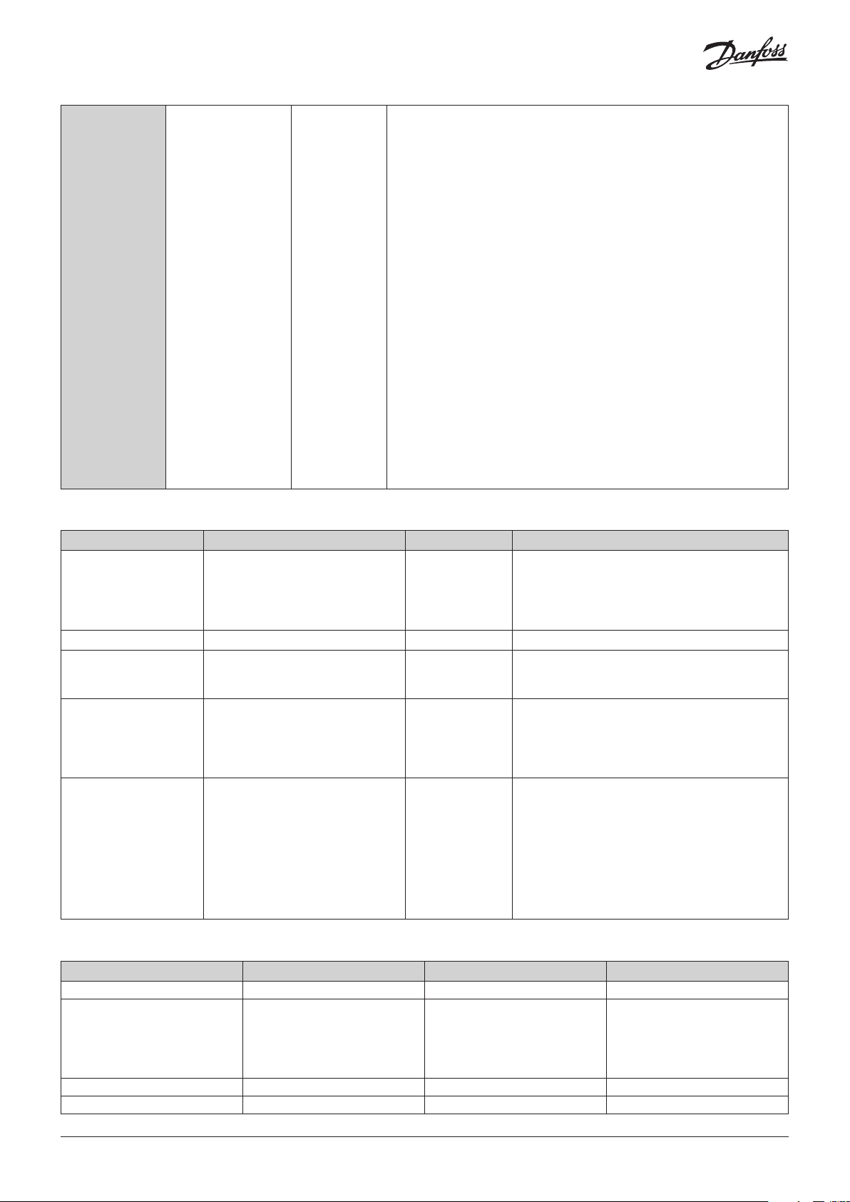
Digital
output
Communication interface
Interface Use Connector label Technical data
CANbus Fieldbus for connection to user
USB device Prepared for future use USB-DEV Plug: Type Mini B
USB host For connection to Flash drive
RS485-1
RS485-2 (MCX20B2 only)
Ethernet For web server functionality,
Relay 20 (MCX20B2)
15 (MCX15B2)
interfaces, MCX controllers, service
tools etc.
for application software update,
datalogging and service
Communication bus to BMS (e.g.
Modbus slave), service tools, smart
devices (e.g. Modbus master)
RS485-1 can be polarized as master
from the application
integration (e.g. Modbus TCP)
NOTICE! Do not route cable outside
of buildings.
Connect only to IT equipment
compliant with EN 60950 or EN
62368 (Information technology
equipment. Safety. General
requirements)
Concerning the insulation distance there are three groups of relays:
• group 1: relays 1 to 8
• group 2: relays 9 to 13
• group 3: relays 14 to 20
Insulation between relays of the same group: functional
Insulation between relays of different groups: reinforced
Insulation between relays and the extra-low voltage parts: reinforced
Total current load limit: 65 A
C1-NO1 to C13-NO13, C16-NO16 to C20-NO20 on MCX20B2
C1-NO1 to C13-NO13 on MCX15B2
Normally open contact relays 5 A
Characteristics of each relay:
– 5 A 250 V AC for resistive loads - 100,000 cycles
– 3 A 250 V AC for inductive loads - 100,000 cycles with cos(phi) = 0.4
– UL: 3 A resistive, 250 V AC, 100,000 cycles; 1/8 hp, 125/250 V AC,
30,000 cycles; C300 pilot duty, 125/250 V AC, 30,000 cycles
C14-NO14-NC14, C15-NO15-NC15
Changeover contact relays 16 A
Characteristics of each relay:
– 7 A 250 V AC for resistive loads - 100,000 cycles
– 3.5 A 250 V AC for inductive loads - 230,000 cycles with cos(phi) = 0.4
– UL: NO contact: 6 A resistive, 240 V AC, 30.000 cycles; 1/2 hp, 240
V AC, 30.000 cycles; 470 VA pilot duty, 240 V AC, 30.000 cycles. NC
contact: 6 A resistive, 6.000 cycles
C3 NO3 to C6 NO6
Optionally they can be solid state relays
Characteristics of each relay:
15-280 Vrms, 0.5 A
UL: 0.5 A resistive, 240 V AC, 30,000 cycles
CAN
CAN-RJ
USB-H Plug: Type A
RS485-1
RS485-2
ETHERNET Interface type: 10 BASE-T and 100 BASE-TX, IEEE
Physical layer according to ISO 11898-2 High
Speed CAN bus
Frame format according to CAN 2.0B specification
Transceiver not isolated (power supply has
reinforced isolation)
Physical layer according to EIA 485 Ref3
Provide 500 V peak transient galvanic isolation
802.3.
MDI-X (Automatic medium-dependent interface
crossover)
Wire lengths
Interface Max wire length (m) Max. baudrate (bps) Min. wire size
Ethernet 100 10/100 M
CANbus 1000
500
250
80
30
RS485 1000 125 K AWG22
Signal wiring 30
4 | AN320819413085en-000401
50 K
125 K
250 K
500 K
1 M
AWG18
AWG22
AWG24
AWG26
AWG26
© Danfoss | DCS (vt) | 2020.10
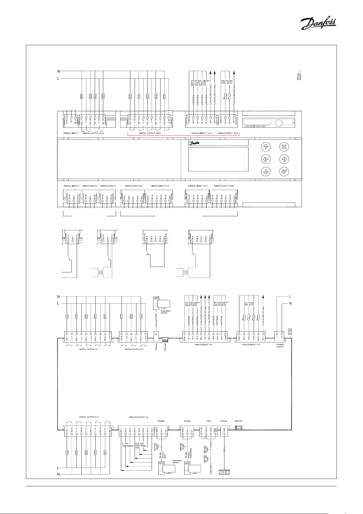
Connection diagram
L
TOP BOARD
MCX20B2 only
N
BOTTOM BOARD
230 V or 24 V DIGITAL INPUT
(DI1 - DI4)
N
L
VOLTAGE FREE or 24 V DIGITAL INPUT
(DI5 - DI22)
24 V230 VOR OR
24 V
SELV
e.g. DIGITAL INPUT 5e.g. DIGITAL INPUT 1
N
L
24 VVOLTAGE FREE
24 V SELV
*)
© Danfoss | DCS (vt) | 2020.10
*)
NOTE: connection has to be made on the first and
last local network units, make the connection as
close as possible to the connector
AN320819413085en-000401 | 5

Connection
Connectors Type Dimensions
Top Board
Digital input 1 connector 3 way screw plug-in connector type • pitch 5 mm
• section cable 0.2 – 2.5 mm²
Digital output 14-15 connector 6 way screw plug-in connector type • pitch 5 mm
• section cable 0.2 – 2.5 mm²
Digital output 16-20 connector (MCX20B2) 10 way screw plug-in connector type • pitch 5 mm
• section cable 0.2 – 2.5 mm²
Analog input 11-14 connector (MCX20B2) 7 way screw plug-in connector type • pitch 5 mm
• section cable 0.2 – 2.5 mm²
Analog input 15-16 connector (MCX20B2) 4 way screw plug-in connector type • pitch 5 mm
• section cable 0.2 – 2.5 mm²
Digital input 2 connector 3 way screw plug-in connector type • pitch 5 mm
• section cable 0.2 – 2.5 mm²
Digital input 3 connector 3 way screw plug-in connector type • pitch 5 mm
• section cable 0.2 – 2.5 mm²
Digital input 4 connector 3 way screw plug-in connector type • pitch 5 mm
• section cable 0.2 – 2.5 mm²
Digital input 5-8 connector 5 way screw plug-in connector type • pitch 5 mm
• section cable 0.2 – 2.5 mm²
Digital input 9-13 connector 6 way screw plug-in connector type • pitch 5 mm
• section cable 0.2 – 2.5 mm²
Digital input 14-17 connector 5 way screw plug-in connector type • pitch 5 mm
• section cable 0.2 – 2.5 mm²
Digital input 18-22 connector 6 way screw plug-in connector type • pitch 5 mm
• section cable 0.2 – 2.5 mm²
Bottom Board
Digital output 1-5 connector 10 way screw plug-in connector type • pitch 5 mm
• section cable 0.2 – 2.5 mm²
Digital output 6-8 connector 6 way screw plug-in connector type • pitch 5 mm
• section cable 0.2 – 2.5 mm²
Ethernet connector 8 / 8 way RJ 45 plug type
USB host connector USB Type A
Analog input 1-6 connector 11 way screw plug-in connector type • pitch 5 mm
• section cable 0.2 – 2.5 mm²
Analog input 7-10 connector 6 way screw plug-in connector type • pitch 5 mm
• section cable 0.2 – 2.5 mm²
Power supply connector 2 way screw plug-in connector type • pitch 5 mm
• section cable 0.2 – 2.5 mm²
Digital output 9-13 connector 10 way screw plug-in connector type • pitch 5 mm
• section cable 0.2 – 2.5 mm²
Analog output 1-6 connector 8 way screw plug-in connector type • pitch 5 mm
• section cable 0.2 – 2.5 mm²
RS485 -2 connector 3 way screw plug-in connector type • pitch 5 mm
• section cable 0.2 – 2.5 mm²
RS485-1connector 3 way screw plug-in connector type • pitch 5 mm
• section cable 0.2 – 2.5 mm²
CAN connector 4 way screw plug-in connector type • pitch 5 mm
• section cable 0.2 – 2.5 mm²
CAN-RJ connector 6/6 way telephone RJ12 plug type
USB DEV connector USB Mini B
6 | AN320819413085en-000401
© Danfoss | DCS (vt) | 2020.10

Dimensions
LCD Display No Display
User interface
LCD Display
display mode: STN blue transmissive
back-light: white LED back-light adjustable via software
display format: 128 x 64 dots
active visible area : 58 x 29 mm
contrast: adjustable via software
Keyboard
number of keys: 6
keys function is settled by the application software
Display settings adjustment
Setting of the LCD display like contrast and brightness might need to be adjusted due to external ambient factors. Press and release
simultaneously the Enter and X key after power ON to access the BIOS menu and select the DISPLAY menu. Use UP and DOWN arrow
keys to adjust the contrast or the brightness of the display at the desired level.
Product part numbers
Description Code No.
MCX15B2, RS485, S 080G0327
MCX15B2, LCD, RS485, S 080G0328
MCX20B2, 2xRS485, I (12 pieces) 080G0329
MCX20B2, LCD, 2xRS485, S 080G0330
MCX20B2, LCD, 2xRS485, I (12 pieces) 080G0331
MCX20B2, LCD, 4 SSR, 2xRS485, S 080G0332
Note: single pack codes (S) include standard kit connectors,
industrial pack codes (I) don’t include standard kit connectors
Accessories part numbers
Description Code No.
MCX20B2 CONNECTORS KIT 080G0404
© Danfoss | DCS (vt) | 2020.10
AN320819413085en-000401 | 7

Replacement of MCX15B-20B with MCX15B2-20B2 through wiring kit
MCX15/20B2
11
From the unit to MCX15/20B
You can replace MCX15/20B with an equivalent model of MCX15/20B2. The same application software runs on both versions
without any change and the universal power supply (24 V AC - 110 V AC - 230 VAC) of MCX15/20B2 facilitates the selection of the
equivalent model.
But there are the following differences that must be taken into consideration:
• The pinout is slightly different for some of the Input/Output (see below the suggested connection diagram)
• The NC (Normally Closed) signals for relay DO10, DO11, DO12 and DO13 are not available in MCX15/20B2. But they are
available for DO14 (as in MCX15B) (and for DO15 as in MCX15/20B). An external relay must be used if these signals are needed.
Alternatively, the application can be changed to take advantage of the additional NC14 signal of MCX20B2.
• The Analogue Outputs (AO) in MCX15/20B2 are internally powered, therefore you must not connect the L1 signal
• 24 V DC power supply is not supported by MCX15/20B2 (40 – 230 V DC)
• The Digital Inputs are both contact free and 24 V sensing in MCX15/20B2, but the DI common signals (DIC) in MCX15/20B2 are
internally connected, therefore you must ensure that DIC are connected to the same phase before the replacement.
For facilitating the replacement of MCX15/20B with B2, you can build a wiring kit following these instructions:
Wiring kit specifications:
Cables:
L = 200 mm H05V-K WHITE
DO: section = 1 mm²
DI: section = 0.5 mm²
AO: section = 0.5 mm²
Connectors:
Phoenix FKIC (or equivalent): Wire strip lenght = 10 mm
Phoenix MSTP (or equivalent): End sleeves = PKD 508/PKD 108 (Danfoss P/N: 080G0404, provided with MCX15/20B2 Single Pack)
D09-12
11 ways
1
D013
3 ways
Phoenix FKIC
Connector
(not provided)
Wiring kit (example)
Connector
provided with
MCX15/20B2
(Single Pack)
D09-13
10 ways
Danfoss
80G465
8 | AN320819413085en-000401
© Danfoss | DCS (vt) | 2020.10

From the unit to
Wiring kit
32
65
11
33
55
77
Connection diagram – from MCX20B to MCX20B2
MCX20B to be
replaced
DIGITAL OUTPUT
DO1-5
10 ways
DO6-8
6 ways
DO9-12
11 ways
1C9
2NO9
3NC10
4C10
5NO10
6NC11
7C11
8NO11
9NC12
10 C12
11 NO12
DO13
3 ways
1NC13
2C13
3NO13
Phoenix FKIC
1910762
1
2
3
4
5
6
7
8
9
10
11
Phoenix FKIC
1910681
1
2
3
Wiring Kit
direct connection
direct connection
DO9-13
10 ways
1)
1)
1)
1)
NOTE: an external relay must be
used if the NC contact is
needed. See the note at the end
of this guide.
Phoenix MSTB
(MCX20B2
connectors)Phoenix FKIC Wires
DO9-13
10 ways
1
C9
2
NO9
3
C10
4
NO10
5
C11
6
NO11
7
C12
8
NO12
9
C13
10
NO13
MCX20B2
board
DO1-5
DO6-8
DO9-13
Danfoss
80G466
Danfoss
DO14-16
7 ways
Phoenix FKIC
1910720
1C16 1
DO14-15
6 ways
80G467
2NO162 1NC15
3C15
4NO154 3NO15
5NC145 4NC14
6C14
C15
DO14-15
C14
7NO147 6NO14
DO17-20
8 ways
1C20
Phoenix FKIC
1910733
DO16-20
10 ways
C20
2NO202 2NO20
3C19
4NO194 4NO19
5C18
6NO186 6NO18
7C17
8NO178 8NO17
DIGITAL INPUT
DI1
3 ways
DI2
3 ways
DI3
3 ways
direct connection
direct connection
direct connection
C19
C18
C17
9
C16
10 NO16
DO16-20
DI1
DI2
DI3
DI4
3 ways
DI5-8
5 ways
© Danfoss | DCS (vt) | 2020.10
direct connection
direct connection
DI4
DI5-8
AN320819413085en-000401 | 9

11
DI9-13
55
54
54
ANALOGUE OU
11
22
33
44
DI9-12
Danf
80G468
5 ways
1DI9
Phoenix FKIC
1910704
6 ways
DI9
2DI102 2DI10
3DI113 3DI11
4DI124 4DI12
5DIC
DI13-16
5 ways
Phoenix FKIC
1910704
1DI131
DI13
6DIC
DI14-17
5 ways
DI9-13
2DI142 1DI14
3DI153 2DI15
4DI164 3DI16
5DIC
DI17
DI14-17
5DIC
DI17-20
5 ways
1DI171
Phoenix FKIC
1910704
DI18-22
6 ways
2DI182 1DI18
3DI193 2DI19
4DI204 3DI20
5DIC
DI21
DI18-22
5DI22
6DIC
DI21-22
4 ways
Phoenix FKIC
1910694
1DI211
2DI222
3DIC 3
4DIC 4
NOTE: the DIC signals in MCX20B2 are internally connected, therefore you
must ensure that DIC are connected to the same phase before the
replacement
ANALOG INPUT
AI1-6
11 ways
AI7-10
6 ways
AI11-14
7 ways
AI15-16
4 ways
TPUT
AO1-4
6 ways
Phoenix FKIC
1910717
1AO1
2AO2
3AO3
4AO4
5L15 5AO5
direct connection
direct connection
direct connection
direct connection
AO1-6
8 ways
AO1
AO2
AO3
AO4
AI1-6
AI7-10
AI11-14
AI15-16
AO1-6
6N16 6AO6
AO5-6
4 ways
1AO6 1
2AO5 2
3N13
4N14
Phoenix FKIC
1910694
NOTE: the AO signals in MCX20B2 are internally
powered, therefore you must not connect L1
7AOC
8AOC
oss
10 | AN320819413085en-000401
© Danfoss | DCS (vt) | 2020.10

Connection diagram – from MCX15B to MCX15B2
42
75
08
21
Wiring Kit
From the unit to
Danf
80G469
MCX15B to be
replaced
(MCX15B2
connectors)Phoenix FKIC Wires
MCX15B2
board
DIGITAL OUTPUT
Phoenix MSTB
DO1-5
10 ways
DO6-8
6 ways
DO9-12
11 ways
Phoenix FKIC
1910762
1C91
2NO9 2
3NC103 1C9
1)
4C10
5NO105 3C10
6NC116 4NO10
1)
7C11
8NO118 6NO11
9NC129 7C12
1)
10 C121
11 NO12 11 9C13
direct connection
direct connection
DO9-13
10 ways
NO9
C11
NO12
DO1-5
DO6-8
DO9-13
NO1310
DO13
3 ways
1NC131
2C13 2
3NO133
DO15
3 ways
1NC151
2C15
Phoenix FKIC
1910681
Phoenix FKIC
1910720
1)
NOTE: an external relay must be
used if the NC contact is
needed. See the note at the end
of this guide.
DO14-15
6 ways
NC15
3NO153 2C15
DO14
3 ways
1NC141
2C14 2
3NO143
Phoenix FKIC
1910720
4NC14
5C14
6NO14
3NO15
DO14-15
DIGITAL INPUT
DI1
3 ways
DI2
3 ways
DI3
3 ways
DI4
3 ways
DI5-8
5 ways
© Danfoss | DCS (vt) | 2020.10
direct connection
direct connection
direct connection
direct connection
direct connection
DI1
DI2
DI3
DI4
DI5-8
oss
AN320819413085en-000401 | 11

Phoenix FKIC
11
DI9-13
55
54
32
43
11
22
33
44
DI9-12
5 ways
1DI9
1910704
6 ways
DI9
2DI1 02 2DI10
3DI1 13 3DI11
4DI1 24 4DI12
5DIC
DI13-16
5 ways
1DI1 31
Phoenix FKIC
1910704
DI13
6DIC
DI14-17
5 ways
DI9-13
2DI142 1DI14
3DI153 2DI15
4DI164 3DI16
5DIC
DI17
DI14-17
5DIC
DI17-18
4 ways
1DI1 71
Phoenix FKIC
1910694
DI18-22
6 ways
2DI182 1DI18
3DIC
4DIC
NOTE: the DIC signals in MCX15B2 are
internally connected, therefore you must
DI19
DI20
4DI21
5DI22
6DIC
DI18-22
ensure that DIC are connected to the
same phase before the replacement.
ANALOGUE INPUT
AI1-6
11 ways
direct connection
AI1-6
AI7-10
6 ways
AI11-14
7 ways
AI15-16
4 ways
ANALOGUE OUTPUT
AO1-4
6 ways
Phoenix FKIC
1910717
1AO1
2AO2
3AO3
4AO4
5L15 5AO5
direct connection
direct connection
direct connection
AO1-6
8 ways
AO1
AO2
AO3
AO4
AI7-10
AI11-14
AI15-16
AO1-6
6N16 6AO6
AO5-6
4 ways
1AO6 1
2COM 2
3AO5 3
Phoenix FKIC
1910720
NOTE: the AO signals in MCX15B2 are
internally powered, therefore you
7AOC
8AOC
must not connect L1.
NOTE: AO5,6 are not isolated in
MCX15B, and the COM is in common
with other signals.
AO5,6 are isolated in MCX15B2, and the
reference is AOC.
12 | AN320819413085en-000401
Danfoss
80G470
© Danfoss | DCS (vt) | 2020.10

Phoenix FKIC
42
75
08
DO9-12
80G471
1
) External Relay connection diagram
(when the NC10, NC11, NC12, NC13 signals are needed).
Example for NC13
11 ways
1C91
2NO9 2
1910762
DO9-13
10 ways
3NC103 1C9
4C10
NO9
5NO105 3C10
6NC116 4NO10
7C11
C11
8NO118 6NO11
9NC129 7C12
10 C121
NO12
11 NO12 11 9C13
NO1310
DO13
3 ways
1NC131
2C13 2
Phoenix FKIC
1910681
External Relay
24 VAC
3NO133
DO9-13
Danfoss
© Danfoss | DCS (vt) | 2020.10
AN320819413085en-000401 | 13

Via San Giuseppe 38/G
Danf
already on order pro
All trademarks in this material are property of the respec
31015 Conegliano
(TV) Italy
Tel: +39 0438 336611
Fax: +39 0438 336699
info.mcx@danfoss.com
www.danfoss.com
oss can accept no responsibility for possible errors in catalogues, brochures and other printed material. Danfoss reserves the right to alter its products without notice. This also applies to products
vided that such alterations can be made without subsequential changes being necessary eady agreed.
tive companies. Danfoss and the Danfoss logotype are trademarks of Danfoss A/S. All rights reserved.
© Danfoss | DCS (vt) | 2020.10
AN320819413085en-000401 | 14
 Loading...