

Page 1
Data Sheet
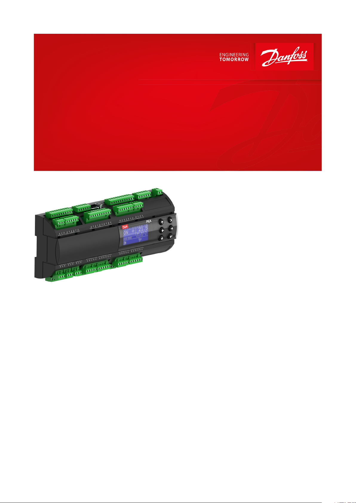
Programmable controller, 15 and 20 relays
Type MCX15B2 and MCX20B2
Electronic controller suitable for all HVAC/R software application needs.
MCX15B2 and MCX20B2 is an electronic
controller that stands on the top of the MCX
range, thanks to the large number of its inputs
and outputs, the enhanced CPU capabilities
and connectivity features.
It holds all the typical functionalities of MCX
controllers:
• programmability
• connection to the CANbus local network
• up to two Modbus RS485 serial interfaces
with galvanic isolation
Furthermore, it is tted with an ultra wide
range (24/110/230 V AC) power supply in the
same product variant, with USB and Ethernet
connection for embedded Web server and IP
protocols management. It is available in several
models, with or without graphic LCD display
and with 15 or 20 digital output.
AI320818679084en-000401
Page 2
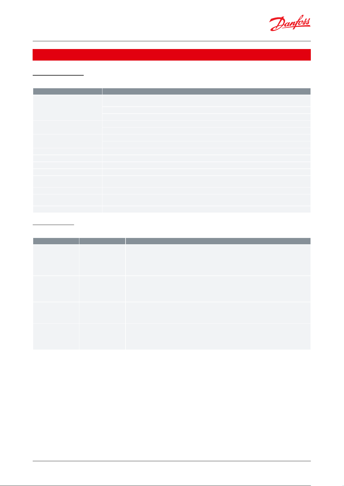
MCX family
MCX06C
MCX06D
MCX061V
MCX08M2
MCX152V
MCX15B2
MCX20B2
Product image
Power supply
24 V
24 V
24 V or
110/230 V
24 V or
110/230 V
24 V or
110/230 V
24/110/230 V
24/110/230 V
Built-in display (optional)
LED
LCD
LCD
LCD
LCD
LCD
LCD
Analog Inputs44781410
16
Digital Inputs68881822
22
Analog Outputs
2334666
Digital Outputs66681515
20
EXV driver embedded
1
2
RS485111121
2
CANbus••••••
•
Ethernet / Web server
optional
optional••
USB/Memory Card
•••
•
Dimensions
(1 DIN module = 17,5
mm)
33 x 75 mm
4 DIN
8 DIN
8 DIN
16 DIN
16 DIN
16 DIN
Programmable controller, 15 and 20 relays, type MCX15B2 and MCX20B2
Features
• MCX20B2
⁃ 16 analog and 22 digital inputs
⁃ 6 analog and 20 digital outputs
• MCX15B2
⁃ 10 analog and 22 digital inputs
⁃ 6 analog and 15 digital outputs
• Ultra wide range power supply from 24 – 230 V AC
• USB connector for easy software upload and datalogging
• Ethernet with Web server feature and several IP protocols
• Remote access to data through CANbus connection for additional display and keyboard
• RTC clock for managing weekly time programs and data logging information with supercapacitor as temporary
backup power
• Up to two Modbus RS485 opto-isolated serial interface
• Available with and without graphic LCD display
• Dimensions 16 DIN modules
Portfolio overview
Table 1: Portfolio overview
© Danfoss | Climate Solutions | 2021.03 AI320818679084en-000401 | 2
Page 3
Features
Description
Power supply
21 – 265 V AC, 50/60 Hz
40 – 230 V DC
Maximum power consumption: 15 W
Isolation between power supply and the extra-low voltage: reinforced
Plastic housing
DIN rail mounting complying with EN 60715
Self-extinguishing V0 according to IEC 60695-11-10 and glowing / hot wire test at 960 °C according to IEC 60695-2-12
Ball test
125 °C according to IEC 60730-1
Leakage current: ≥ 250 V according to IEC 60112
Operating conditions
CE: -20T60 / UL: 0T50, 90% RH non-condensing
Storage conditions
-30T80, 90% RH non-condensing
Integration
In Class I and / or II appliances
Index of protection
IP40 only on the front cover
Period of electric stress across insulating parts
Long
Resistance to heat and re
Category D
Immunity against voltage surges
Category II
Category III for versions without display
Software class and structure
Class A
Type
Num
Specications
Total number: 16 on MCX20B2; 10 on MCX15B2
Analog Input type selectable via software.
Max 13.5 V input voltage.
Do not connect voltage sources without current limitation (overall 80 mA) to analog inputs while unit is not
powered.
Open circuit HW diagnostics available for all analog inputs.
NTC
0 / 1 V
0 / 5 V
0 / 10 V
PT1000
16 (MCX20B2)
10 (MCX15B2)
AI1 to AI16 on MCX20B2
AI1 to AI10 on MCX15B2
NTC, default 10 kΩ at 25 °C, Beta 3435
0/xV type: impedance is greater than 1 MΩ
ON/OFF
0 / 20 mA
4 / 20 mA
10 (MCX20B2)
6 (MCX15B2)
AI1 to AI6, AI11 to AI14 on MCX20B2
AI1 to AI6 on MCX15B2
100 Ω as measuring resistance for current measurements.
The inputs can be used to sense voltage free contacts with contact cleaning current 10 mA.
Auxiliary Supplies
15 V+ and 5 V+
5 V+ max: 200 mA (total on all outputs)
15 V+ max: 200 mA (total on all outputs)
All power outputs are protected against short circuit and have an automatic recovery from overload
condition.
Programmable controller, 15 and 20 relays, type MCX15B2 and MCX20B2
Product specication
General features
Table 2: General features
Input/Output
Table 3: Analog inputs
© Danfoss | Climate Solutions | 2021.03 AI320818679084en-000401 | 3
Page 4

Type
Num
Specications
Total number: 22
Digital Input type selectable via software between 24 V AC or voltage free
Voltage free contacts or
24 V AC
18
DI5 to DI22
As the inputs are not isolated, caution has to be used when applying 24 V AC: the same polarity of the supply
MUST always be used on COM/GND connection. Counting function with max frequency of 16.6 Hz (30 ms
minimum pulse time).
24 V opto-insulated
4
DI1, DI2, DI3, DI4
Inputs opto isolated, 24 V AC 50/60 Hz or 24 V DC
Rated current: 5 mA @24 V AC
230 V opto-insulated
4
DIH1, DIH2, DIH3, DIH4
Inputs opto isolated, 86 – 265 V AC / 50/60 Hz
Reinforced isolation
Rated current: 2,5 mA @ 265 V AC
NOTE:
When the 230 V AC DH1 input is used, the corresponding 24 V DI1 input is not available anymore; the same
for the couple of inputs DIH2 and DI2, DIH3 and DI3, DIH4 and DI4.
Type
Num
Specications
Total number: 6
0 / 10 V
6
AO1, AO2, AO3, AO4, AO5, AO6
Analog Outputs 0/10 V, galvanically isolated, minimum load 1K Ω (10 mA) for each output.
PWM-PPM
2
AO5, AO6
Asynchronous PWM
Voltage output: max VLO= 0.6 V, min VHI= 6.5 V
Frequency range 15 Hz…1 kHz
Synchronous PWM and PPM
Voltage output: max VLO= 0.6 V, min VHI= 6.5 V
Frequency: Mains frequency x2
I/O
Type
Num
Specications
Digital output
Relay
20 (MCX20B2)
15 (MCX15B2)
Concerning the insulation distance there are three groups of relays:
• group 1: relays 1 to 8
• group 2: relays 9 to 13
• group 3: relays 14 to 20
Insulation between relays of the same group: functional
Insulation between relays of dierent groups: reinforced
Insulation between relays and the extra-low voltage parts: reinforced
Total current load limit: 65 A
C1-NO1 to C13-NO13, C16-NO16 to C20-NO20 on MCX20B2
C1-NO1 to C13-NO13 on MCX15B2
Normally open contact relays 5 A
Characteristics of each relay:
•
5 A 250 V AC for resistive loads - 100,000 cycles
•
3 A 250 V AC for inductive loads - 100,000 cycles with cos(phi) = 0.4
• UL: 3 A resistive, 250 V AC, 100,000 cycles; 1/8 hp, 125/250 V AC, 30,000 cycles; C300 pilot
duty, 125/250 V AC, 30,000 cycles
C14-NO14-NC14, C15-NO15-NC15
Changeover contact relays 16 A
Characteristics of each relay:
• 5 A 250 V AC for resistive loads - 100,000 cycles
• 3.5 A 250 V AC for inductive loads - 230,000 cycles with cos(phi) = 0.4
• UL: NO contact: 6 A resistive, 240 V AC, 30.000 cycles; 1/2 hp, 240 V AC, 30.000 cycles; 470
VA pilot duty, 240 V AC, 30.000 cycles. NC contact: 6 A resistive, 6.000 cycles
C3 NO3 to C6 NO6
Optionally they can be solid state relays
Characteristics of each relay:
• 15 – 280 Vrms, 0.5 A
• UL: 0.5 A resistive, 240 V AC, 30,000 cycles
Programmable controller, 15 and 20 relays, type MCX15B2 and MCX20B2
Table 4: Digital inputs
Table 5: Analog outputs
Table 6: Digital outputs
© Danfoss | Climate Solutions | 2021.03 AI320818679084en-000401 | 4
Page 5

Interface
Use
Connector label
Technical data
CANbus
Fieldbus for connection to user interfaces, MCX
controllers, service tools etc.
CAN
CAN-RJ
Physical layer according to ISO 11898-2 High Speed CAN bus
Frame format according to CAN 2.0B specication Transceiver
not isolated (power supply has reinforced isolation)
USB device
Prepared for future use
USB-DEV
Plug: Type Mini B
USB host
For connection to Flash drive for application software update, datalogging and service
USB-H
Plug: Type A
RS485-1
RS485-2 (MCX20B2
only)
Communication bus to BMS (e.g. Modbus slave),
service tools, smart devices (e.g. Modbus master)
RS485-1 can be polarized as master from the application
RS485-1
RS485-2
Physical layer according to EIA 485 Ref3
Provide 500V peak transient galvanic isolation
Ethernet
For web server functionality, integration (e.g.
Modbus TCP) NOTICE! Do not route cable outside
of buildings. Connect only to IT equipment compliant with EN 60950 or EN 62368 (Information
technology equipment. Safety. General requirements)
ETHERNET
Interface type: 10 BASE-T and 100 BASE-TX, IEEE 802.3. MDI-X
(Automatic medium-dependent interface crossover)
Interface
Max wire length (m)
Max. baudrate (bps)
Min. wire size
Ethernet
100
10/100 M
CANbus
1000
520
250
80
30
50 K
125 K
250 K
500 K
1 M
AWG18
AWG22
AWG24
AWG26
AWG26
RS485
1000
125 K
AWG22
Signal wiring
30
Programmable controller, 15 and 20 relays, type MCX15B2 and MCX20B2
Communication interface
Table 7: Communication interface
Wire lengths
Table 8: Wire lengths
© Danfoss | Climate Solutions | 2021.03 AI320818679084en-000401 | 5
Page 6

24 V
SELV
24 V SELV
230 V or 24 V DIGITAL INPUT
(DI1 - DI4)
24 V230 V OR
OR
N
L
N
L
N
L
24 VVOLTAGE FREE
VOLTAGE FREE or 24 V DIGITAL INPUT
(DI5 - DI22)
e.g. DIGITAL INPUT 5
e.g. DIGITAL INPUT 1
MCX20B2 only
Programmable controller, 15 and 20 relays, type MCX15B2 and MCX20B2
Connection diagram
Top board
Figure 1: Top board
© Danfoss | Climate Solutions | 2021.03 AI320818679084en-000401 | 6
Page 7

*)
Connectors
Type
Dimensions
Digital input 1 connector
3 way screw plug-in connector type
• pitch 5 mm
• section cable 0.2 – 2.5 mm²
Digital output 14-15 connector
6 way screw plug-in connector type
• pitch 5 mm
• section cable 0.2 – 2.5 mm²
Digital output 16-20 connector (MCX20B2)
10 way screw plug-in connector type
• pitch 5 mm
• section cable 0.2 – 2.5 mm²
Analog input 11-14 connector (MCX20B2)
7 way screw plug-in connector type
• pitch 5 mm
• section cable 0.2 – 2.5 mm²
Analog input 15-16 connector (MCX20B2)
4 way screw plug-in connector type
• pitch 5 mm
• section cable 0.2 – 2.5 mm²
Digital input 2 connector
3 way screw plug-in connector type
• pitch 5 mm
• section cable 0.2 – 2.5 mm²
Digital input 3 connector
3 way screw plug-in connector type
• pitch 5 mm
• section cable 0.2 – 2.5 mm²
Digital input 4 connector
3 way screw plug-in connector type
• pitch 5 mm
• section cable 0.2 – 2.5 mm²
Digital input 5-8 connector
5 way screw plug-in connector type
• pitch 5 mm
• section cable 0.2 – 2.5 mm²
Programmable controller, 15 and 20 relays, type MCX15B2 and MCX20B2
Bottom board
Figure 2: Bottom board
NOTE:
Connection has to be made on the rst and last local network units, make the connection as close as possible to the
connector.
Connection
Table 9: Top board
© Danfoss | Climate Solutions | 2021.03 AI320818679084en-000401 | 7
Page 8

Connectors
Type
Dimensions
Digital input 9-13 connector
6 way screw plug-in connector type
• pitch 5 mm
• section cable 0.2 – 2.5 mm²
Digital input 14-17 connector
5 way screw plug-in connector type
• pitch 5 mm
• section cable 0.2 – 2.5 mm²
Digital input 18-22 connector
6 way screw plug-in connector type
• pitch 5 mm
• section cable 0.2 – 2.5 mm²
Connectors
Type
Dimensions
Digital output 1-5 connector
10 way screw plug-in connector type
• pitch 5 mm
• section cable 0.2 – 2.5 mm²
Digital output 6-8 connector
6 way screw plug-in connector type
• pitch 5 mm
• section cable 0.2 – 2.5 mm²
Ethernet connector
8 / 8 way RJ 45 plug type
USB host connector
USB Type A
Analog input 1-6 connector
11 way screw plug-in connector type
• pitch 5 mm
• section cable 0.2 – 2.5 mm²
Analog input 7-10 connector
6 way screw plug-in connector type
• pitch 5 mm
• section cable 0.2 – 2.5 mm²
Power supply connector
2 way screw plug-in connector type
• pitch 5 mm
• section cable 0.2 – 2.5 mm²
Digital output 9-13 connector
10 way screw plug-in connector type
• pitch 5 mm
• section cable 0.2 – 2.5 mm²
Analog output 1-6 connector
8 way screw plug-in connector type
• pitch 5 mm
• section cable 0.2 – 2.5 mm²
RS485 -2 connector
3 way screw plug-in connector type
• pitch 5 mm
• section cable 0.2 – 2.5 mm²
RS485-1 connector
3 way screw plug-in connector type
• pitch 5 mm
• section cable 0.2 – 2.5 mm²
CAN connector
4 way screw plug-in connector type
• pitch 5 mm
• section cable 0.2 – 2.5 mm²
CAN-RJ connector
6/6 way telephone RJ12 plug type
USB DEV connector
USB Mini B
Programmable controller, 15 and 20 relays, type MCX15B2 and MCX20B2
Table 10: Bottom board
Dimensions
Figure 3: Dimensions
© Danfoss | Climate Solutions | 2021.03 AI320818679084en-000401 | 8
Page 9

Type
Features
Description
LCD display
Display
STN blue transmissive
Backlight
White LED backlight adjustable via software
Contrast
Adjustable via software
Format
128 x 64 dots
Active visible area
58 x 29 mm
Keyboard
Number of keys
6
Keys function
Set by the application software
Description
Code No.
MCX15B2, RS485, S
080G0327
MCX15B2, LCD, RS485, S
080G0328
MCX20B2, 2xRS485, I (12 pieces)
080G0329
MCX20B2, LCD, 2xRS485, S
080G0330
MCX20B2, LCD, 2xRS485, I (12 pieces)
080G0331
MCX20B2, LCD, 4 SSR, 2xRS485, S
080G0332
Description
Code No.
MCX20B2 Connectors Kit
080G0404
File name
Document type
Document topic
Approval authority
080R1230.01
EU Declaration of conformity
EMC directive 2014/30/EU:
EN61000-6-3: 2007 +A1: 2011
EN61000-6-2: 2005
LVD directive 2014/35/EU:
EN60730-1: 2011
EN60730-2-9: 2010
RoHS directive 2011/65/EU and 2015/863/EU:
EN 50581: 2012
Danfoss
UL E31024
Electrical - Safety
Certicate
–
UL
Programmable controller, 15 and 20 relays, type MCX15B2 and MCX20B2
User interface
Table 11: User interface
Ordering
Product part numbers
Table 12: Product part numbers
NOTE:
Single pack codes (S) include standard kit connectors, industrial pack codes (I) don’t include standard kit connectors.
Accessories part numbers
Table 13: Accessories part numbers
Certicates, declarations, and approvals
The list contains all certicates, declarations, and approvals for this product type. Individual code number may have
some or all of these approvals, and certain local approvals may not appear on the list.
Some approvals may change over time. You can check the most current status at danfoss.com or contact your local
Danfoss representative if you have any questions.
Table 14: Certicates, declarations, and approvals
© Danfoss | Climate Solutions | 2021.03 AI320818679084en-000401 | 9
Page 10

Online support
Danfoss oers a wide range of support along with our products, including digital product information, software,
mobile apps, and expert guidance. See the possibilities below.
The Danfoss Product Store
The Danfoss Product Store is your one-stop shop for everything product related—no matter where
you are in the world or what area of the cooling industry you work in. Get quick access to essential
information like product specs, code numbers, technical documentation, certications, accessories,
and more.
Start browsing at store.danfoss.com.
Find technical documentation
Find the technical documentation you need to get your project up and running. Get direct access to
our ocial collection of data sheets, certicates and declarations, manuals and guides, 3D models
and drawings, case stories, brochures, and much more.
Start searching now at www.danfoss.com/en/service-and-support/documentation.
Danfoss Learning
Danfoss Learning is a free online learning platform. It features courses and materials specically
designed to help engineers, installers, service technicians, and wholesalers better understand the
products, applications, industry topics, and trends that will help you do your job better.
Create your Danfoss Learning account for free at www.danfoss.com/en/service-and-support/learning.
Get local information and support
Local Danfoss websites are the main sources for help and information about our company and
products. Find product availability, get the latest regional news, or connect with a nearby expert—all
in your own language.
Find your local Danfoss website here: www.danfoss.com/en/choose-region.
Danfoss can accept no responsibility for possible errors in catalogues, brochures and other printed material. Danfoss reserves the right to alter its
products without notice. This also applies to products already on order provided that such alterations can be made without subsequential
changes being necessary in specications already agreed. All trademarks in this material are property of the respective companies. Danfoss and
the Danfoss logotype are trademarks of Danfoss A/S. All rights reserved.
© Danfoss | Climate Solutions | 2021.03 AI320818679084en-000401 | 10
 Loading...