

Page 1
Installation Guide
520H9703
®
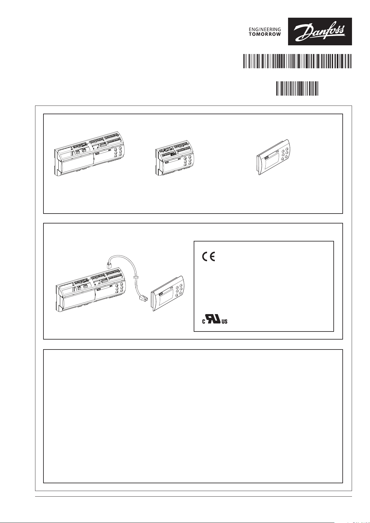
MCX rooftop controller
Instruction guide
Identication:
520H9703
MCX152V
Ordering no.
080G0304 = 110/230vac
Connection:
MCX08M (Optional)
Ordering no.
080G0029 = 110/230vac
DKRCC.PI.RI0.L1.22
520H9703
MMIGRS2 (Optional)
Ordering no.
080G0294
IP 20
-20 – 60 °C (0 – 140 °F)
RH max. 90% non condensing
CE COMPLIANCE
This product is designed to comply with the following EU standards:
Low voltage guideline: 73/23/EEC Electromagnetic compatibility EMC:
89/336/EEC and with the following norms:
EN61000-6-1, EN61000-6-3 (immunity for residential, commercial and
light-industrial environments)
EN61000-6-2, EN61000-6-4 (immunity and emission standard for
industrial environments)
EN60730 (Automatic electrical controls for household and similar use)
UL APPROVAL
UL file: E31024
Technical data:
Supply Voltage
85 – 265 V AC, 50/60 Hz
Maximum power consumption: 27 W, 48 VA
DO - Digital outputs, 15 pcs. DO1 – DO15
DO1 - DO15, all are relays, no solid state relays
The relays are de-rated to the specified values
Insulation between power supply and the extra-low
voltage: reinforced
AO - Analog output, 6 pcs. AO1 – AO6
Outputs are 0 – 10 V DC by default
Plugs normally not used
Stepper Motor 1, Stepper Motor 2, Stepper Backup,
RS485-2, Digital Input 18
AI - Analog Inputs, 14 pcs. AI1 – AI14
All temperature sensors default to PT1000, Pressure
transducers default to 0.5 – 4.5 V DC ratiometric with
Modbus
5 V DC supply. All other inputs are 0 – 5 V DC by default
It is important that the installation of the data
communication cable be installed correctly.
Remember to terminate each end of the bus.
See separate literature No. RC8AC.
© Danfoss | DCS (za) | 2015.08 Installation guide | MCX rooftop controller
DI - Digital switch inputs DI1 – DI17
All Dry contacts except DI17,
(24 V AC or 230 V AC driven)
DKRCC.PI.RI0.L1.22 / 520H9703 | 1
Page 2
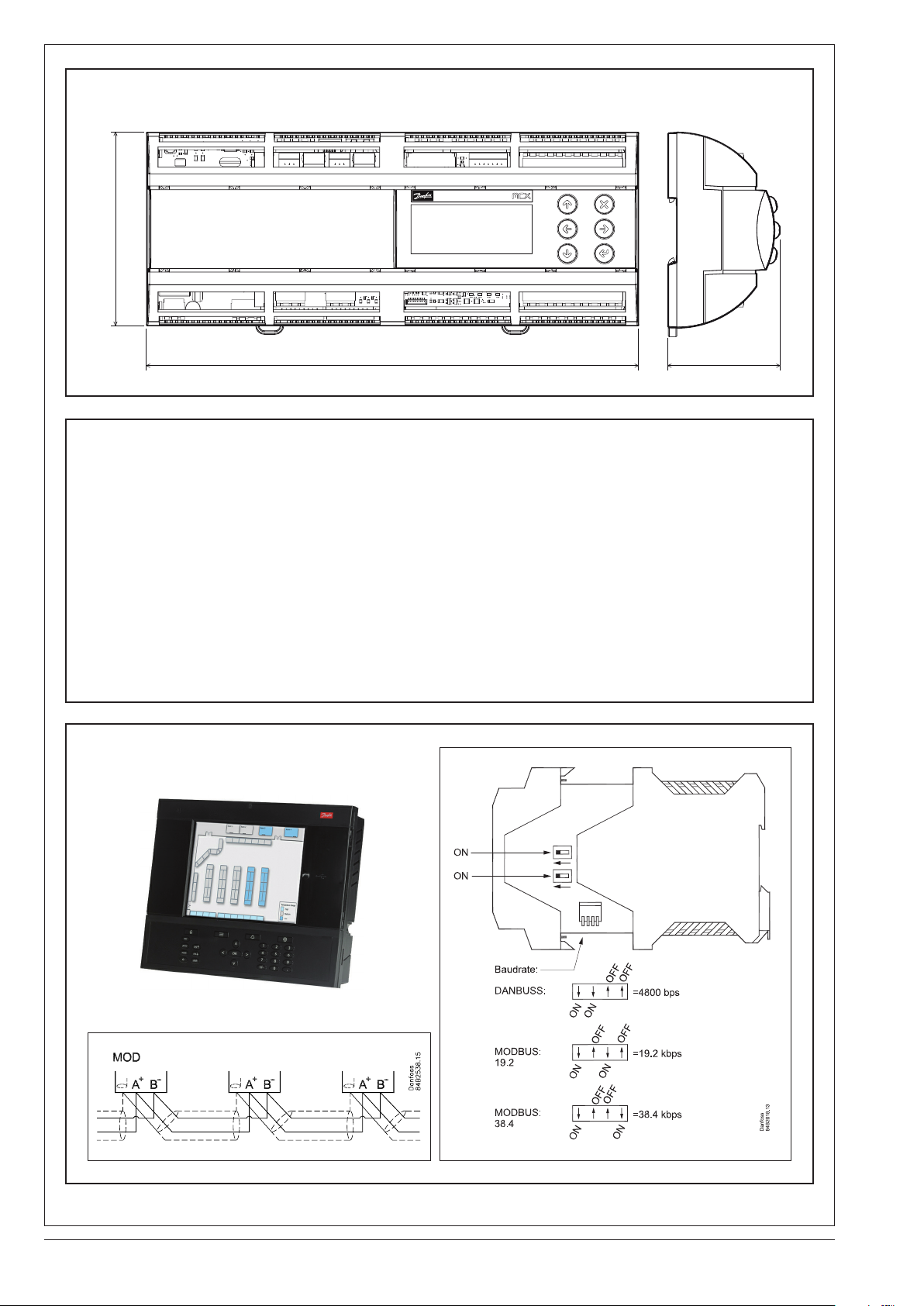
Dimensions:
110 mm - 4.33 in.
280 mm - 11.02 in. 63 mm - 2.48 in.
Modbus topology:
The cable must be EIA485 rated. The cable is connected from controller to controller, and no branches are allowed on the
cable. If the cable length exceeds 1200 m a repeater must be inserted. One repeater must be added for every 32 controllers.
If the data communication cable runs through an electrically noisy environment which impairs the data signal, one or more
repeaters must be added to stabilise the signal.
When configuring Modbus devices on the control bus, the highest device address that can be used is 124
(max 120 modbus control devices in total - max 45 MCX RTC).
The wires are looped from device to device. A is connected to A and B is connected to B. The screen must be connected to the
system device, all controller and any repeaters. A screen must always be looped from device to device.
The screen must not be connected to anything else.
See AK-SM800 User Guide for system 485 wiring instructions.
Manual can be found at: http://food-retail.danfoss.com/knowledge-center/software/ak-sm-800/
Be sure to configure the Modbus repeater AKA 222 (code#084B2240) to the correct baud rate.
MCX-RTU baud rate must be set to 38.4 K when used with the AK-SM800. MCX-RTU cannot be on the same 485 bus with SLVs.
AK-SM800:
Repeater
Termination
2 |DKRCC.EI.RL0.I1.02 / 520H9646 © Danfoss | DCS (za) | 2015.08Installation guide | MCX rooftop controller
Page 3

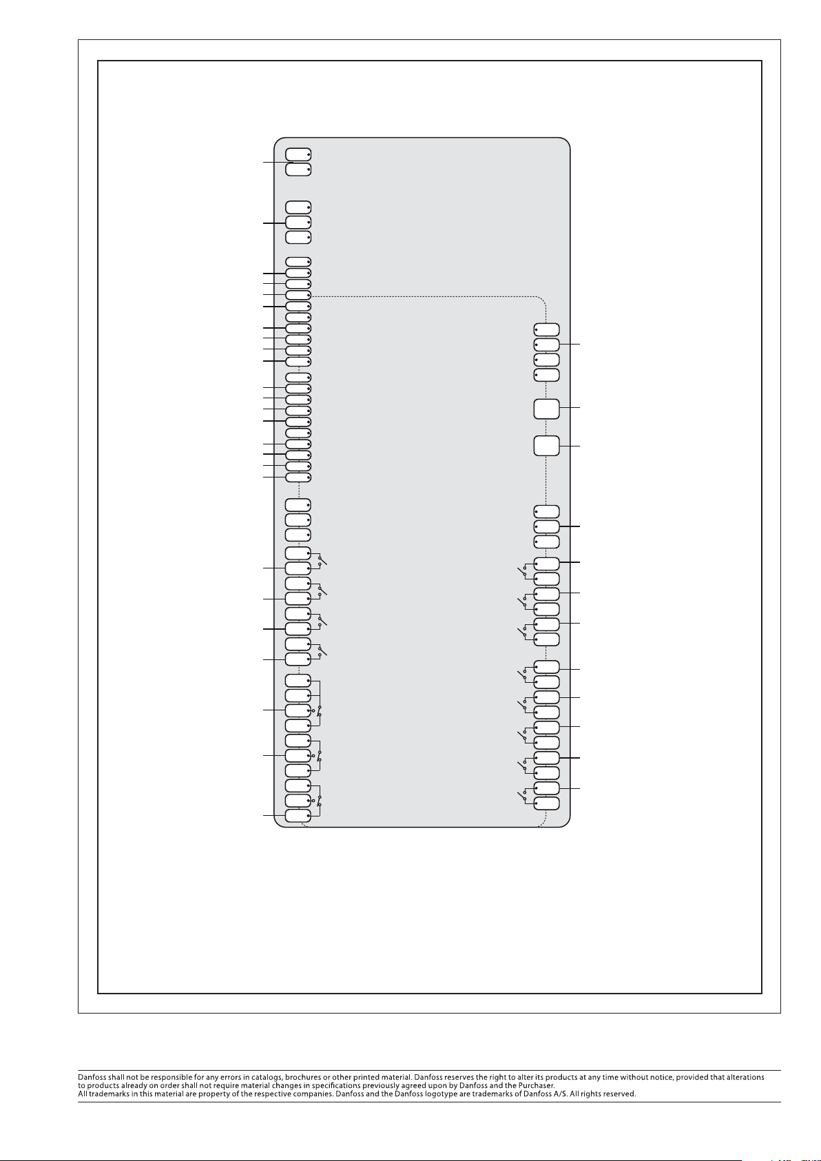
Wiring Diagram MCX152V -bottom and top
COM 1
Modbus connection
D1 +
D1 -
COM 2
D2 +
D2 -
RS485-1
RS485-2
MCX152V TOP
MOTOR 2
STEPPER
MOTOR 1
STEPPER
MEMORY CARD
ST2 4
ST2 3
ST2 2
ST2 1
ST1 4
ST1 3
ST1 2
ST1 1
Not used
SD/MMC
Mixed Air (PT1000)
Outdoor Temp (PT1000)
Fan CT (0 – 5 V DC)
Compr 1 Press (5 V DC)
Compr 2 Press (5 V DC)
Compr 3 Press (5 V DC)
Compr 4 Press (5 V DC)
AI 8
AI 9
AI 10
AI 11
5V+
15V+
COM
COM
AI 12
AI 13
AI 14
ANALOG INPUT 8-14
AO 6
ANALOG OUTPUT 1-6 ANALOG INPUT 1-7
AO 5
AO 4
COM
AO 3
AO 2
AO 1
COM
AI 7
AI 6
AI 5
COM
COM
15V+
5V+
AI 4
AI 3
AI 2
AI 1
Damper AO
VS compressors 4
VS compressors 3
VS compressors 2
VS compressors 1
Fan AO
DP Outside/Mixed Air
Zone CO2(0 – 5 V DC)
Outdoor RH(0 – 5 V DC)
Zone RH(0 – 5 V DC)
Return Air(PT1000)
Supply Air(PT1000)
Zone Temp(PT1000)
DKRCC.EI.RL0.I1.02 / 520H9646 | 3© Danfoss | DCS (za) | 2015.08 Installation guide | MCX rooftop controller
Page 4
Wiring Diagram MCX152V -bottom and top
SUPPLY
Input Voltage
110 – 230 V AC
Stepper Backup
NOT USED
Fan Proof
Phase Loss
Shutdown 1
Shutdown 2
Fan Drive Fault
Compr 1 Drive Fault
Compr 2 Drive Fault
Compr 3 Drive Fault
Compr 4 Drive Fault
Filter Clogged Fault
Damper Override
Title 24
Schedule Override
Cool 1 Proof
Cool 2 Proof
Cool 3 Proof
Reheat (N.O.)
Damper (N.O.)
Heat Reclaim 1 (N.O.)
Heat Reclaim 1 (N.O.)
Heat Pump (N.O.)
Fan Low Speed (N.O.)
Fan High Speed (N.C.)
L
N
COM
+ BATT
15V+
COM
DI 1
DI 2
DI 3
DI 4
COM
DI 5
DI 6
DI 7
DI 8
COM
DI 9
DI 10
DI 11
DI 12
COM
DI 13
DI 14
DI 15
DI 16
DI 18H
DI 18
COM 18
C 9
NO 9
C 10
NO 10
C 11
NO 11
C 12
NO 12
C 13
C 13
NO 13
NC 13
C 14
NO 14
NC 14
C 15
NO 15
NC 15
POWER
STEPPER BACKUP DIGITAL INPUT 1-8 DIGITAL INPUT 9-16
DIGITAL INPUT 18
DIGITAL OUTPUT 9-12 DIGITAL OUTPUT 13-15
MCX152V BOTTOM
COM
CANCAN-RJ
CANL
CANH
R120
CAN-RJ
ETHERNET DIGITAL INPUT 17
ETH
COM 17
DI 17
DI 17H
DIGITAL OUTPUT 6-8
NO 8
C 8
NO 7
C 7
NO 6
C 6
NO 5
C 5
DIGITAL OUTPUT 1-5
NO 4
C 4
NO 3
C 3
NO 2
C 2
NO 1
C 1
Optional IO Expansion
Optional - Remote Display
Not Used
Cool 4 Proof
Aux Heat 4 (N.O.)
Aux Heat 3 (N.O.)
Aux Heat 2 (N.O.)
Aux Heat 1 (N.O.)
Cool 4 (N.O.)
Cool 3 (N.O.)
Cool 2 (N.O.)
Cool 1 (N.O.)
Contact info:
www.danfoss.com
© Danfoss | DCS (za) | 2015.08
Installation guide | MCX rooftop controller DKRCC.EI.RL0.I1.02 / 520H9646 | 4
 Loading...