

Installation Guide
Electronic controller
080R9348
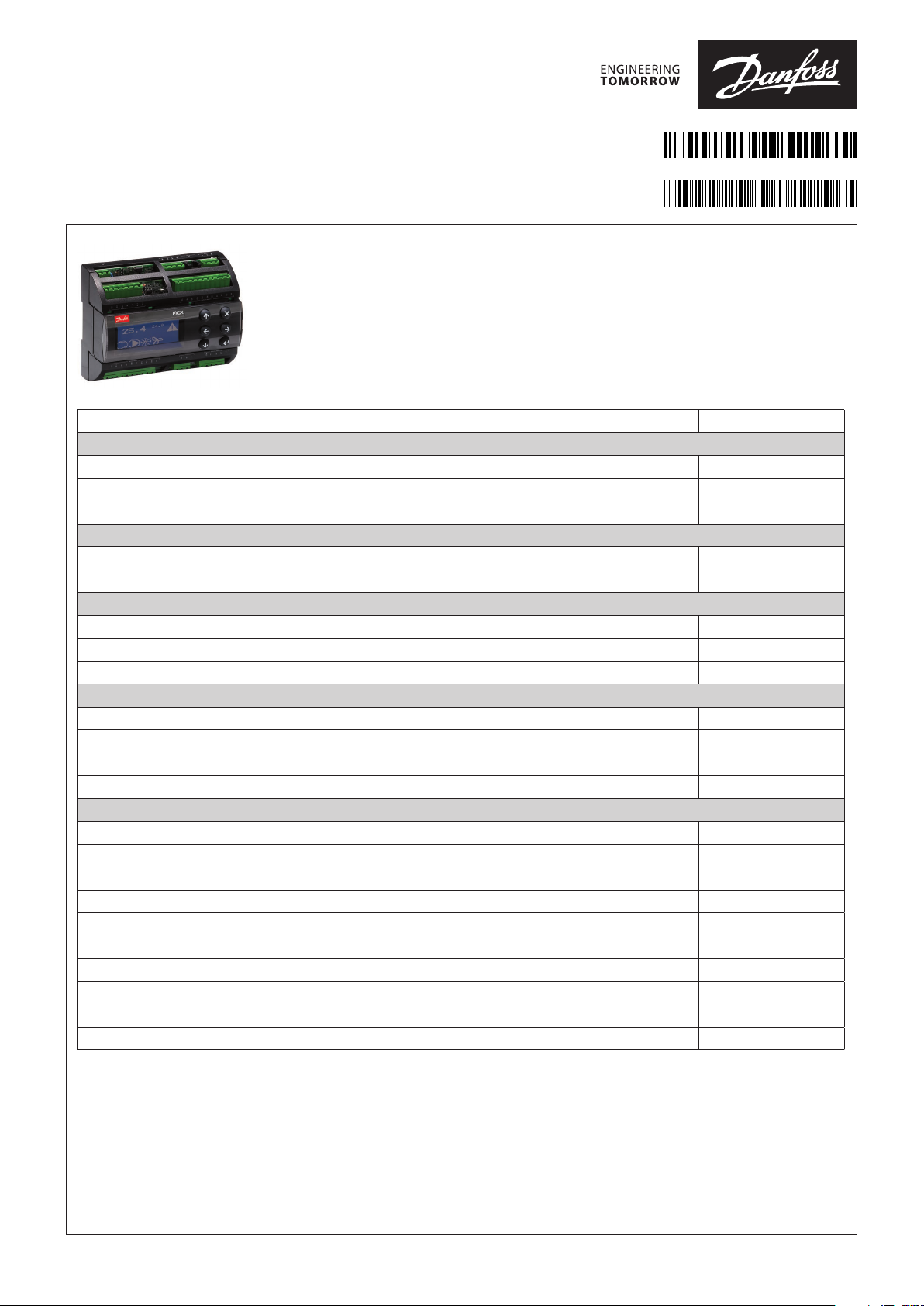
MCX08M2 with TTL
General features:
MCX08M2 is an electronic controller that holds all the typical functionalities of MCX controllers
in the compact size of 8 DIN modules: programmability, connection to the CANbus local
network, Modbus RS485 serial communication interface.
MCX08M2 with TTL version is moreover available in the version with display and power supply
110 – 230 V AC.
ANALOG INPUTS
NTC, 0/1 V, 0/5 V, 0/10 V, PT1000, selectable via software 4
Universal NTC, Pt1000, 0/1 V, 0/5 V, 0/10 V, ON/OFF, 0/20 mA, 4/20 mA, selectable via software 4
Total number 8
DIGITAL INPUTS
Voltage free contact 8
Total number 8
ANALOG OUTPUTS
0/10 V DC optoinsulated 2
0/10 V DC, PWM, PPM selectable via software 2
Total number 4
DIGITAL OUTPUTS
SPST relay 16 A (normally open contacts) 2
SPST relay 8 A (normally open contacts) 2
SPDT relay 8 A (changeover contacts) 4
Total number 8
OTHERS
Power supply 110 V / 230 V AC •
Connection for programming key •
Connection for remote display and keyboard •
Buzzer •
CANbus •
RTC clock •
Modbus RS485 serial interface •
Serial TTL •
Dimensions (DIN modules) 8
Mounting DIN rail
AN358818754869en-000201
MCX08M2 with TTL
© Danfoss | DCS (vt) | 2021.01
AN358818754869en-000201 | 1

General features and warnings
Plastic housing features
• DIN rail mounting complying with EN 60715
• Self extinguishing V0 according to IEC 60695-11-10 and glowing/hot wire test at 960 °C according to IEC 60695-2-12
• Ball test: 125 °C according to IEC 60730-1. Leakage current: ≥ 250 V according to IEC 60112
Other features
• Operating conditions CE: -20T60 / UL: 0T55, 90% RH non-condensing
• Storage conditions: -30T80, 90% RH non-condensing
• To be integrated in Class I and/or II appliances
• Index of protection: IP40 only on the front cover
• Period of electric stress across insulating parts: long
• Suitable for use in environments with degree of pollution 2
• Category of resistance to heat and fire: D
• Immunity against voltage surges: category II
• Software class and structure: class A
Compliance
This product is designed to comply with the following EU standards:
• Low voltage directive LVD 2014/35/EU:
– EN60730-1: 2011 (Automatic electrical control for household and similar use. General requirements)
– EN60730-2-9: 2010 (Particular Requirements for Temperature Sensing Controls)
• Electromagnetic compatibility EMC directive 2014/30/EU:
– EN 61000-6-3: 2007 +A1: 2011 (Emission standard for residential, commercial and light-industrial environments)
– EN 61000-6-2: 2005 (Immunity for industrial environments)
• RoHS directive 2011/65/EU and 2015/863/EU:
– EN50581: 2012
UL approval:
• UL file E31024
General warnings
• Every use that is not described in this manual is considered incorrect and is not authorised by the manufacturer
• Verify that the installation and operating conditions of the device respect the ones specified in the manual, specially concerning the
supply voltage and environmental conditions
• This device contains live electrical components therefore all the service and maintenance operations must be performed by qualified
personnel
• The device can’t be used as a safety device
• Liability for injury or damage caused by the incorrect use of the device lies solely with the user
Installation warnings
• Mounting position recommended: vertical
• The installation must be executed according the local standards and legislation of the country
• Always operate on the electrical connections with the device disconnected from the main power supply
• Before carrying out any maintenance operations on the device, disconnect all the electrical connections
• For safety reasons the appliance must be fitted inside an electrical panel with no live parts accessible
• Don’t expose the device to continuous water sprays or to relative humidity greater than 90%.
Avoid exposure to corrosive or pollutant gases, natural elements, environments where explosives or mixes of flammable gases are
present, dust, strong vibrations or chock, large and rapid fluctuations in ambient temperature that in combination with high humidity
can condensate, strong magnetic and/or radio interference (e.g. transmitting antennae)
• When connecting loads beware of the maximum current for each relay and connector
• Use cable ends suitable for the corresponding connectors. After tightening the screws of connectors, slightly tug the cables to check
their tightness
• Use appropriate data communication cables. Refer to the Fieldbus Installation Guide for the kind of cable to be used and setup
recommendations
• Reduce the path of the probe and digital inputs cables as much as possible, and avoid spiral paths enclosing power devices. Separate
from inductive loads and power cables to avoid possible electromagnetic noises
• Avoid touching or nearly touching the electronic components fitted on the board to avoid electrostatic discharges
Disposal instruction
Equipment containing electrical components may not be disposed together with domestic waste. It must be separately collected
with electrical and electronic waste according to local and valid legislation.
2 | AN358818754869en-000201
© Danfoss | DCS (vt) | 2021.01

Technical specifications
Power supply
• 85 – 265 V AC, 50/60 Hz. Maximum power consumption: 20 VA. Insulation between power supply and the extra-low voltage: reinforced
• 20 – 60 V DC e 24 V AC ± 15% 50/60 Hz SELV. Maximum power consumption: 10 W, 17 VA. Insulation between power supply and the
extra-low voltage: functional
I/O TYPE NUM SPECIFICATIONS
Analog
inputs
Digital
input
Analog
outputs
Digital
output
NTC
0 / 1V
0 / 10V
PT1000
Universal 4 AI1, AI2, AI3, AI4
Voltage free contact 8 DI1, DI2, DI3, DI4, DI5, DI6, DI7, DI8
0 / 10 V DC optoins 2 AO3, AO4
PWM
PPM
0 / 10 V DC
Relay 8 Insulation between relay: functional
4 AI5, AI6, AI7, AI8
Analog inputs selectable via software between:
• 0 / 1 V, 0 / 5 V, 0 / 10 V : impedance is greater than 1M Ω
• NTC (10 kΩ at 25 °C)
• Pt1000
Universal analog inputs selectable via software between:
• ON/OFF (current: 20 mA)
• 0/1 V, 0/5 V, 0/10 V : impedance is greater than 1M Ω
• 0/20 mA, 4/20 mA
• NTC (10 kΩ at 25 °C)
• Pt1000
12 V+ power supply 12 V DC, 120 mA max for 4/20 mA transmitter (total
on all outputs)
5 V+ power supply 5 V DC, 100 mA max for 0/5 V transmitter (total on all
outputs)
Current consumption: 10 mA
• Analog outputs optoinsulated 0/10 V DC minimum load 1K Ω (10 mA)
for each output
2 AO1, AO2
Analog outputs selectable via software between:
• 0/10 V dc minimum load 1K Ω (10 mA) for each output
• pulsing output, synchronous with the line, at modulation of impulse
position (PPM) or modulation of impulse width (PWM)
• pulsing output, at modulation of impulse position (PPM) with range 20
Hz to 1 KHz: open circuit voltage: 6.8 V
Insulation between relays and the extra-low voltage parts: reinforced
Total current load limit: 32 A
C1-NO1, C2-NO2
High inrush current (80 A - 20 ms) normally open contact relays 16 A
Characteristics of each relay:
• 10 A 250 V AC for resistive loads - 100.000 cycles
• 3.5 A 230 V AC for inductive loads - 230.000 cycles with cos(phi) = 0.5
C5-NO5, C6-NO6
Normally open contact relays 8 A
Characteristics of each relay:
• 6 A 250 V AC for resistive loads - 100.000 cycles
• 4 A 250 V AC for inductive loads - 100.000 cycles with cos(phi) = 0.6
C3-NO3-NC3, C4-NO4-NC4, C7-NO7-NC7, C8-NO8-NC8
Changeover contacts relay 8 A
Characteristics of each relay:
• 6 A 250 V AC for resistive loads - 100.000 cycles
• 4 A 250 V AC for inductive loads - 100.000 cycles with cos(phi) = 0.6
© Danfoss | DCS (vt) | 2021.01
AN358818754869en-000201 | 3

Connection diagram
TOP BOARD
PWM-PPM
0/10 Vdc
0/10 V
optoinsulated
Not
used
To the AI
(120 mA max)
To the AI
(100 mA max)
only for 080G0335
TTL
MCX08M2 - TOP
BOTTOM BOARD
COM
RXTXDIR
5V/AUX
NTC, 0/1 V, 0/5 V,
0/10 V, PT1000
Danfoss
80G8036.04
4 | AN358818754869en-000201
MCX08M2 - BOTTOM
© Danfoss | DCS (vt) | 2021.01

Connection
110
Connectors Type Dimensions
Top Board
Analog output 1-4 connector 7 way screw plug-in connector type
Analog input 1-4 connector 11 way screw plug-in connector type
Digital input 1-8 connector 10 way screw plug-in connector type
Analog input 5-8 connector 5 way screw plug-in connector type
TTL connector (only for 080G0335) 5 way spring plug-in connector type
Bottom Board
Power supply connector 2 way screw plug-in connector type
CAN connector 4 way screw plug-in connector type
CAN-RJ connector 6/6 way telephone RJ12 plug type
RS485 connector 3 way screw plug-in connector type
Digital output 1-2 connector 4 way screw plug-in connector type
Digital output 3-4 connector 6 way screw plug-in connector type
Digital output 5-6 connector 4 way screw plug-in connector type
Digital output 7-8 connector 6 way screw plug-in connector type
• pitch 5 mm
• section cable 0.2 – 2.5 mm²
• pitch 5 mm
• section cable 0.2 – 2.5 mm²
• pitch 5 mm
• section cable 0.2 – 2.5 mm²
• pitch 5 mm
• section cable 0.2 – 2.5 mm²
• pitch 2.5 mm
• section cable 0.2 – 2.5 mm²
• pitch 5 mm
• section cable 0.2 – 2.5 mm²
• pitch 5 mm
• section cable 0.2 – 2.5 mm²
• pitch 5 mm
• section cable 0.2 – 2.5 mm²
• pitch 5 mm
• section cable 0.2 – 2.5 mm²
• pitch 5 mm
• section cable 0.2 – 2.5 mm²
• pitch 5 mm
• section cable 0.2 – 2.5 mm²
• pitch 5 mm
• section cable 0.2 – 2.5 mm²
User interface
LCD Display
Display mode: STN blue transmissive
Backlight: white LED backlight adjustable via software
Display format: 128 x 64 dots
Active visible area : 58 x 29 mm
Contrast: adjustable via software
Keyboard
Number of keys: 6
Keys function is settled by the application software
Display settings adjustment
Setting of the LCD display like contrast and brightness might need to be adjusted due to external ambient factors. Press and release
simultaneously the Enter and X key after power ON to access the BIOS menu and select the DISPLAY menu. Use UP and DOWN arrow
keys to adjust the contrast or the brightness of the display at the desired level.
Dimensions
LCD Display No Display
Danfoss
80G8037.01
140 6063
© Danfoss | DCS (vt) | 2021.01
AN358818754869en-000201 | 5

Product part numbers
Description Code No.
MCX08M2, 230 V, LCD, RS485, TTL, Single Pack 080G0335
Accessories part numbers
Description Code No.
MCX08M CONNECTORS KIT 080G0180
6 | AN358818754869en-000201
© Danfoss | DCS (vt) | 2021.01
 Loading...