

Page 1
Data Sheet
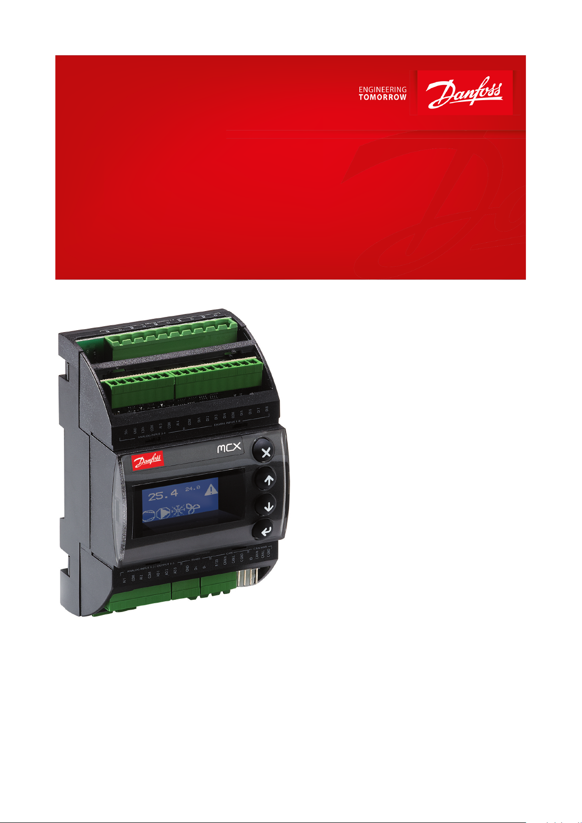
Programmable controller, 6 relays
Type MCX06D
Electronic controller suitable for all HVAC/R software application needs.
MCX06D is tted with graphic LCD display or
without display. It is an electronic controller
that holds all the typical functionalities of MCX
controllers in the compact size of 4 DIN
modules:
• programmability
• connection to the CANbus local network
• Modbus RS485 opto-insulated serial interface
Features:
• 4 analog and 8 digital inputs
• 3 analog and 6 digital outputs
• Power supply 20 / 60 V DC - 24 V AC
• Remote access to data through CANbus
connection for additional display (LCD
available) and keyboard
• RTC clock for managing weekly time
programs and data logging information
• Modbus RS485 opto-insulated serial interface
• Available with graphic LCD display or without
display for showing the desired information
• Dimensions 4 DIN modules
AI183786420819en-000601
Page 2
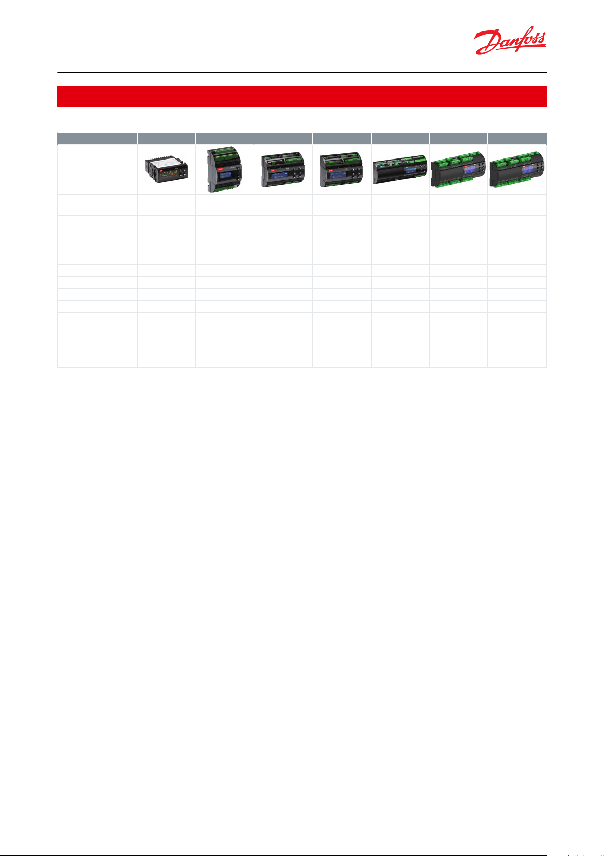
MCX family
MCX06C
MCX06D
MCX061V
MCX08M2
MCX152V
MCX15B2
MCX20B2
Product image
Power supply
24 V
24 V
24 V or
110/230 V
24 V or
110/230 V
24 V or
110/230 V
24/110/230 V
24/110/230 V
Built-in display (optional)
LED
LCD
LCD
LCD
LCD
LCD
LCD
Analog Inputs44781410
16
Digital Inputs68881822
22
Analog Outputs
2334666
Digital Outputs66681515
20
EXV driver embedded
1
2
RS485111121
2
CANbus••••••
•
Ethernet / Web server
optional
optional••
USB/Memory Card
•••
•
Dimensions
(1 DIN module = 17,5
mm)
33 x 75 mm
4 DIN
8 DIN
8 DIN
16 DIN
16 DIN
16 DIN
Programmable controller, 6 relays, type MCX06D
Portfolio overview
Table 1: Portfolio overview
© Danfoss | Climate Solutions | 2021.03 AI183786420819en-000601 | 2
Page 3
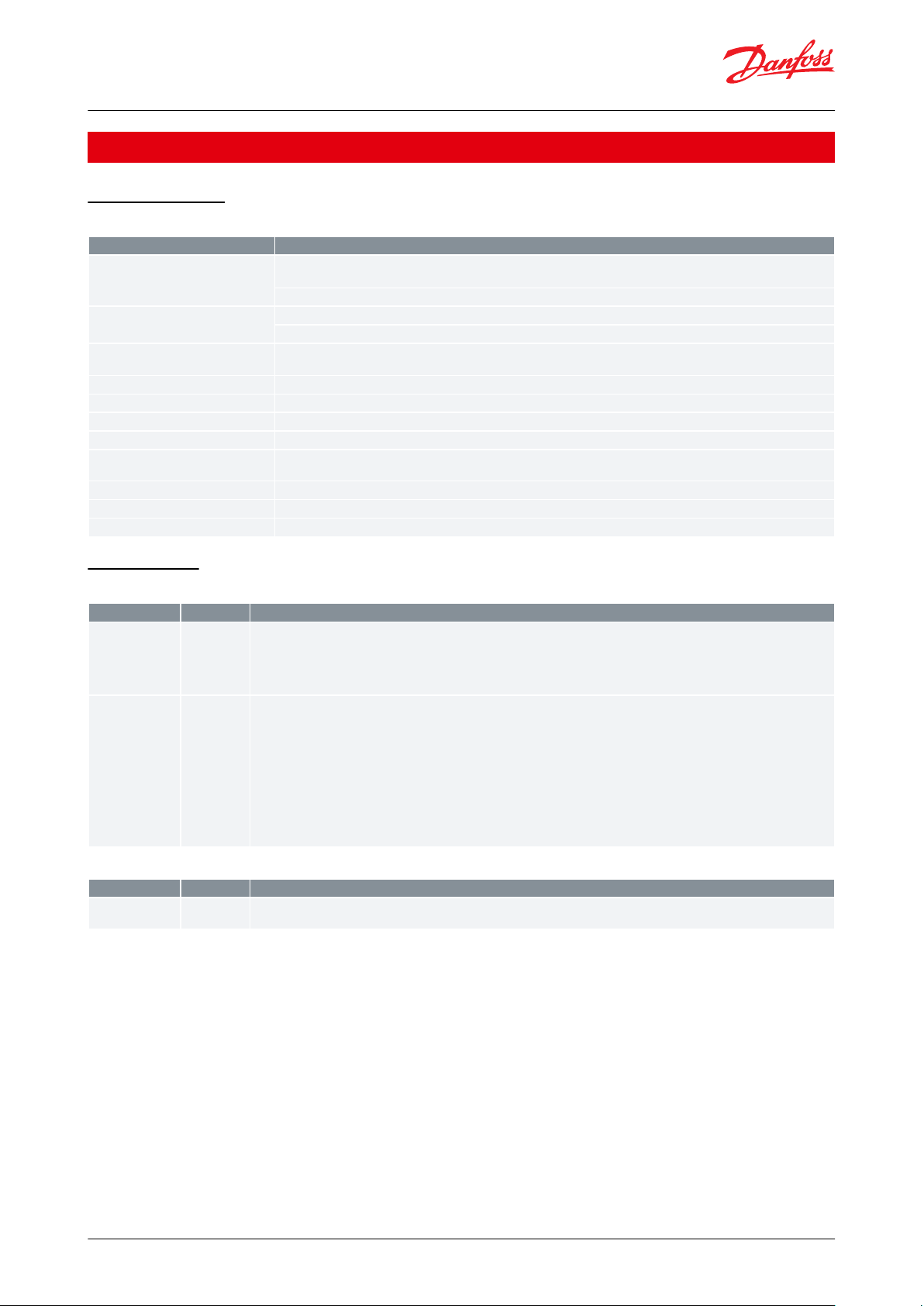
Features
Description
Power supply
20 / 60 V DC and 24 V AC ± 15% 50/60 Hz SELV
Maximum power consumption: 6 W, 9 VA
Insulation between power supply and the extra-low voltage: functional
Plastic housing
DIN rail mounting complying with EN 60715
Self extinguishing V0 according to IEC 60695-11-10 and glowing / hot wire test at 960 °C according to IEC 60695-2-12
Ball test
125 °C according to IEC 60730-1
Leakage current: ≥ 250 V according to IEC 60112
Operating conditions
CE: -20T60 / UL: 0T55, 90% RH non-condensing
Storage conditions
-30T80, 90% RH non-condensing
Integration
In Class I and / or II appliances
Index of protection
IP40 only on the front cover
Period of electric stress across insulating parts
Long
Resistance to heat and re
Category D
Immunity against voltage surges
Category II
Software class and structure
Class A
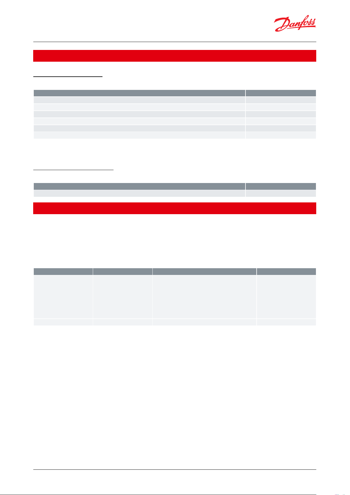
Type
Num
Specications
NTC
0 / 1 V
0 / 5 V
2
AI1, AI2
Analog inputs selectable via software between:
• NTC temperature probes, default: 10 kΩ at 25 °C
• Pressure transducers with 0/5 V output
• 0/5V type: impedance is 18 kΩ
Universal
2
AI3, AI4
Universal analog inputs selectable via software between:
• ON/OFF (current: 20 mA)
• 0 / 1 V, 0 / 5 V, 0 / 10 V
• 0 / 20 mA, 4 / 20 mA
• NTC (10 kΩ at 25 °C)
• Pt1000
12 V+ power supply 12 V DC, 50 mA max for 4 / 20 mA transmitter (total on all outputs)
5 V+ power supply 5 V DC, 80 mA max for 0 / 5 V transmitter (total on all outputs)
0/5V type: impedance is 18 kΩ
0/10V type: impedance is 2 kΩ
Type
Num
Specications
Voltage free contact
6
DI1, DI2, DI3, DI4, DI5, DI6, DI7, DI8
Current consumption: 5 mA
Programmable controller, 6 relays, type MCX06D
Product specication
General features
Table 2: General features
Input/Output
Table 3: Analog inputs
Table 4: Digital inputs
© Danfoss | Climate Solutions | 2021.03 AI183786420819en-000601 | 3
Page 4

Type
Num
Specications
0 / 10 V
PWM
PPM
1
AO1, AO2
Analog outputs selectable via software between:
• pulsing output, synchronous with the line, at modulation of impulse position (PPM) or modulation of impulse width (PWM):
◦ open circuit voltage: 6.8 V
◦ minimum load 1 kΩ (10 mA)
• pulsing output, at modulation of impulse width (PWM) with range 100 – 500 Hz:
◦
open circuit voltage: 6.8 V
◦ minimum load 1 kΩ (10 mA)
• 0 / 10 V DC non optoinsulated output, referred to the ground
◦ minimum load 1 kΩ (10 mA)
PWM
PPM
1
AO3
Analog output selectable via software between:
• pulsing output, synchronous with the line, at modulation of impulse position (PPM) or modulation of impulse width (PWM):
◦ open circuit voltage: 6.8 V
◦ minimum load 1 kΩ (10 mA)
• pulsing output, at modulation of impulse width (PWM) with range 100 – 500 Hz:
◦
open circuit voltage: 6.8 V
◦ minimum load 1 kΩ (10 mA)
Type
Num
Specications
Relay6Insulation between relays 1 to 5: functional
Insulation between relay 6 and the other relays: reinforced
Insulation between relays and the extra-low voltage parts: reinforced
Total current load limit: 33 A
C1-NO1, C2-NO2, C3-NO3, C4-NO4, C5-NO5
Normally open contact relays 5 A
Characteristics of each relay:
•
5 A 30 V DC / 250 V AC for resistive loads - 100.000 cycles
• 0.7 A 250 V AC for inductive load - 100.000 cycles with cos(phi) = 0.5
• UL: 250 V AC - 3 A resistive - 1.5 FLA - 9.0 LRA - 144 V A pilot duty 30.000 cycles
NC6-C6-NO6
Changeover contacts relay 8 A
Characteristics of each relay:
•
8 A 250 V AC for resistive loads - 100.000 cycles
• 4 A 250 V AC for inductive loads - 100.000 cycles with cos(phi) = 0.6
•
UL: 240 V AC - 6 A resistive - 4.9 FLA - 29.4 LRA - 470 V A pilot duty 30.000 cycles
Programmable controller, 6 relays, type MCX06D
Table 5: Analog outputs
Table 6: Digital outputs
© Danfoss | Climate Solutions | 2021.03 AI183786420819en-000601 | 4
Page 5

MCX06D - TOP
MCX06D - BOTTOM
To the AI (80 mA max)
To the AI (50 mA max)
*
CANbus
DI 8
DI 7
DI 6
DI 5
COM
DI 4
DI 3
DI 2
DI 1
COM
AI 4
COM
AI 3
COM
12V+
GND
5V+
AO 3
AO 2
AO 1
D -
R 120
CAN H
CAN L
ID
CAN H
CAN L
D +
GND
COM
AI 2
COM
AI 1
CAN CAN MMIRS485
PWM-PPM
0-10 V PWM-PPM
0-10 V PWM-PPM
N TC 0/5 V
N TC 0/5 V
ANALOG I/O
ANALOG INPUT 3-4 DIGITAL INPUT 1-8
RS485
(Modbus)
supervisory network
CANbus
UNIVERSAL
UNIVERSAL
AO1
AO2
AO3
local network
Power
supply
board
CAN GND
CAN GND
DI 1
DI 2
DI 3
DI 4
DI 5
DI 6
DI 7
DI 8
NTC, Pt1000,
ON/OFF, 0/1 V, 0/5 V,
0/10 V, 0/20 mA
4/20 mA
optoinsulated
RS485
8 A
8 A
5 A
5 A
5 A
5 A
5 A
24 V AC 20÷60 V DC
N
24 V AC Phase sync
NO 1
C 1
NO 2
C 2
NO 3
C 3
NO 4
C 4
NO 5
C 5
N 1
L 1
N SYNC
L SYNC
DIGITAL OUTPUT 1-5
DIGITAL OUTPUT 6SYNCPOWER SUPPLY
L
N
L
N
L
NO 6
C 6
NC 6
N
L
**
Connectors
Type
Dimensions
Analog input 3-4 connector
7 way screw plug-in connector type
• pitch 3.5 mm
• section cable 0.08 – 1.5 mm²
Digital input 1-8 connector
10 way screw plug-in connector type
• pitch 3.5 mm
• section cable 0.08 – 1.5 mm²
Analog I/O connector
7 way screw plug-in connector type
• pitch 3.5 mm
• section cable 0.08 – 1.5 mm²
Programmable controller, 6 relays, type MCX06D
Connection diagram
Figure 1: Connection diagram
NOTE:
*Connection has to be made on the rst and last local network units, make the connection as close as possible to
the connector.
**When AO is used as synchronised output, the sync input must be in phase with the load on AO.
Connection
Table 7: Top board
© Danfoss | Climate Solutions | 2021.03 AI183786420819en-000601 | 5
Page 6

Connectors
Type
Dimensions
RS485 connector
3 way screw plug-in connector type
• pitch 3.5 mm
• section cable 0.08 – 1.5 mm²
CAN connector
4 way screw plug-in connector type
• pitch 3.5 mm
• section cable 0.08 – 1.5 mm²
CAN MMI connector
4 way Connection 2515
Series type
(2515-2041) crimping contact type: Connection
(2500-2001) instrument for the crimp type 1190-1298
• section cable AWG22-28 (0.32 – 0.08 mm²)
Connectors
Type
Dimensions
Digital output 1-5 connector
10 way screw plug-in connector type
• pitch 5 mm
• section cable 0.2 – 2.5 mm²
Power supply connector
2 way screw plug-in connector type
• pitch 3.5 mm
• section cable 0.08 – 1.5 mm²
Sync connector
2 way screw plug-in connector type
• pitch 3.5 mm
• section cable 0.08 – 1.5 mm²
Digital output 6 connector
3 way screw plug-in connector type
• pitch 5 mm
• section cable 0.2 – 2.5 mm²
110
70 63 60
Danfoss
80G8053
Type
Features
Description
LCD display
Display
STN blue transmissive
Backlight
White LED backlight adjustable via software
Contrast
Adjustable via software
Format
98 x 64 dots
Active visible area
29.4 x 19.2 mm
Keyboard
Number of keys
4
Keys function
Set by the application software
Programmable controller, 6 relays, type MCX06D
Table 8: Bottom board
Dimensions
Figure 2: Dimensions
User interface
Table 9: User interface
© Danfoss | Climate Solutions | 2021.03 AI183786420819en-000601 | 6
Page 7
Description
Code No.
MCX06D, 24 V, LCD, S
080G0111
MCX06D, 24 V, LCD, RS485, RTC, S
080G0112
MCX06D, 24 V, RS485, RTC, S
080G0115
MCX06D, 24 V, LCD, I (32 pieces)
080G0166
MCX06D, 24 V, LCD, RS485, RTC, I (32 pieces)
080G0167
MCX06D, 24 V, RS485, RTC, I (32 pieces)
080G0169
Description
Code No.
MCX06D/EXC06D Connectors Kit
080G0179
File name
Document type
Document topic
Approval authority
080R1224.01
EU Declaration of conformity
EMC directive 2014/30/EU:
EN61000-6-4: 2007 +A1:2011
EN61000-6-2: 2005
LVD directive 2014/35/EU:
EN60730-1: 2011
EN60730-2-9: 2010
RoHS directive 2011/65/EU and 2015/863/EU:
EN 50581: 2012
Danfoss
UL E31024
Electrical - Safety
Certicate
–
UL
Programmable controller, 6 relays, type MCX06D
Ordering
Product part numbers
Table 10: Product part numbers
NOTE:
Single pack codes (S) include standard kit connectors, industrial pack codes (I) don’t include standard kit connectors.
Accessories part numbers
Table 11: Accessories part numbers
Certicates, declarations, and approvals
The list contains all certicates, declarations, and approvals for this product type. Individual code number may have
some or all of these approvals, and certain local approvals may not appear on the list.
Some approvals may change over time. You can check the most current status at danfoss.com or contact your local
Danfoss representative if you have any questions.
Table 12: Certicates, declarations, and approvals
© Danfoss | Climate Solutions | 2021.03 AI183786420819en-000601 | 7
Page 8

Online support
Danfoss oers a wide range of support along with our products, including digital product information, software,
mobile apps, and expert guidance. See the possibilities below.
The Danfoss Product Store
The Danfoss Product Store is your one-stop shop for everything product related—no matter where
you are in the world or what area of the cooling industry you work in. Get quick access to essential
information like product specs, code numbers, technical documentation, certications, accessories,
and more.
Start browsing at store.danfoss.com.
Find technical documentation
Find the technical documentation you need to get your project up and running. Get direct access to
our ocial collection of data sheets, certicates and declarations, manuals and guides, 3D models
and drawings, case stories, brochures, and much more.
Start searching now at www.danfoss.com/en/service-and-support/documentation.
Danfoss Learning
Danfoss Learning is a free online learning platform. It features courses and materials specically
designed to help engineers, installers, service technicians, and wholesalers better understand the
products, applications, industry topics, and trends that will help you do your job better.
Create your Danfoss Learning account for free at www.danfoss.com/en/service-and-support/learning.
Get local information and support
Local Danfoss websites are the main sources for help and information about our company and
products. Find product availability, get the latest regional news, or connect with a nearby expert—all
in your own language.
Find your local Danfoss website here: www.danfoss.com/en/choose-region.
Danfoss can accept no responsibility for possible errors in catalogues, brochures and other printed material. Danfoss reserves the right to alter its
products without notice. This also applies to products already on order provided that such alterations can be made without subsequential
changes being necessary in specications already agreed. All trademarks in this material are property of the respective companies. Danfoss and
the Danfoss logotype are trademarks of Danfoss A/S. All rights reserved.
© Danfoss | Climate Solutions | 2021.03 AI183786420819en-000601 | 8
 Loading...