

Page 1
DESCRIPTION
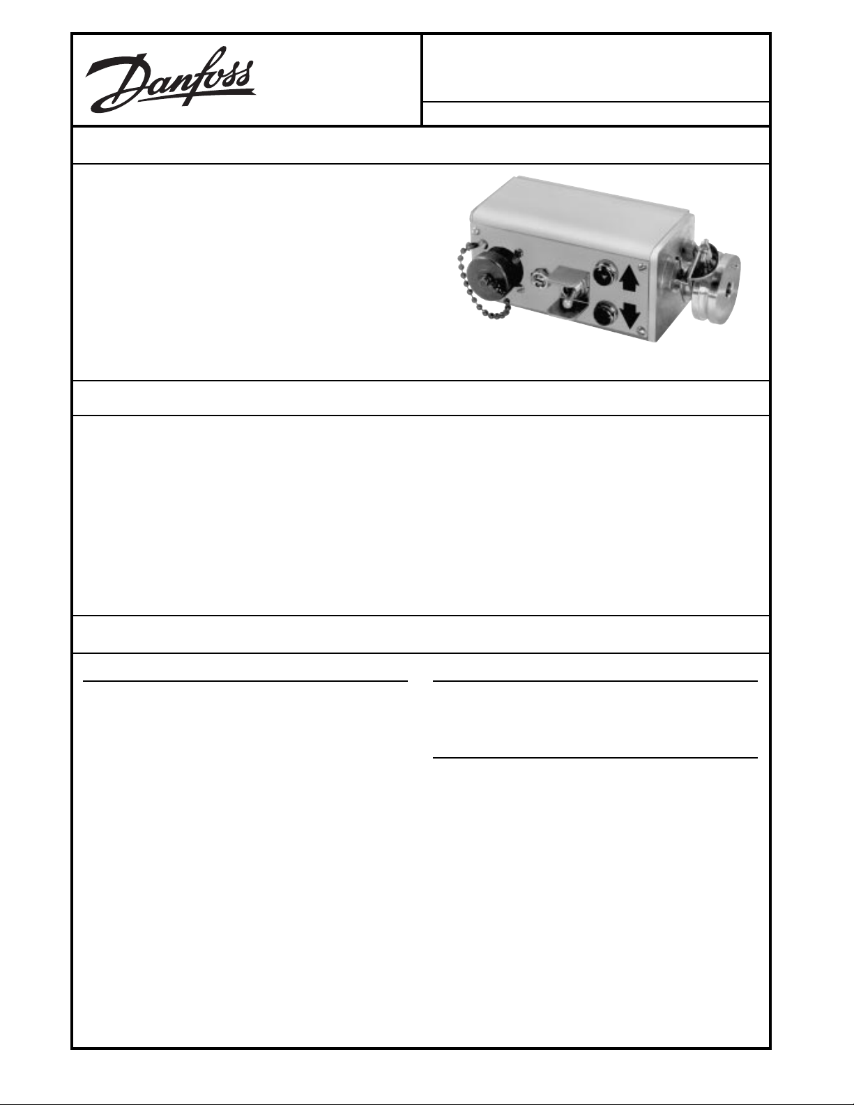
The MCW102B Proportional Rotary Position Controller provides automatic grade and steering control on paving,
curbing and planing machines. It uses a follower arm riding
on a stringline or a ski riding on the prepared surface as a
grade reference. In steering applications, the MCW102B
uses a vertical follower arm riding against a stringline reference. The MCW102B controls servovalves to position a
screed, form cutting drum, or steer cylinder.
FEATURES
MCW102B
Proportional Rotary Position Controller
BLN-95-8970-4 Issued: January 1995
• Non-contacting sensing element for long life
• Fully burned-in components for added reliability
• Bright up/down lights for easy nulling
• Adjustable sensitivity
• Run/Standby switch for manual or automatic control
• Remote setpoint or steering feedback connections available
TECHNICAL DATA
ELECTRICAL
SUPPLY VOLTAGE
12 or 24 Vdc
0.5 amps Does not include output current to load.
MAXIMUM OUTPUT CURRENT @ 14 VDC SUPPLY
170 ± 20 mA with 23 ohm load
The MCW102B drives a number of Danfoss
servovalves.
MAXIMUM REVERSED POLARITY VOLTAGE
50 Vdc for 5 minutes
SHORT CIRCUIT PROTECTION
The controllers are protected against short circuits
across the valve coil as well as shorts between the
outputs and ground. A short circuit is defined as 1 ohm
maximum resistance for 5 minutes maximum.
LOAD DUMP
Protected against load dump per SAE J2.20.97
• Reverse polarity and short circuit protection
• Rugged aluminum housing
• Withstands high vibration and shock
• Moisture and corrosion resistant
• Easy to mount
• Adjustable tracking force
.
MECHANICAL
Physical stops limit the rotation to approximately ± 23° from
null.
ENVIRONMENTAL
OPERATING TEMPERATURE
-18° to 77° C (0° to 170° F)
STORAGE TEMPERATURE
-30° to 65° C (-22° to 150° F)
HUMIDITY
After being placed in a controlled atmosphere of 95%
humidity at 38° C for 10 days, the controller will perform
within specification limits.
RAIN
The controller will withstand exposure to a 15 minute
shower with cold water after reaching the maximum
storage temperature.
© Danfoss, 2013-09 BLN-95-8970-4 1
Page 2
TECHNICAL DATA
(continued)
VIBRATION
Withstands a vibration test designed for mobile equipment controls consisting of two parts:
1. Cycling from 5 to 2000 Hz in each of the three axes.
2. Resonance dwell for one million cycles for each
resonant point in each of the three axes.
Run from 1 g to 8 g’s. Acceleration level varies with
frequency.
DIMENSIONS
SHOCK
50 g for 11 milliseconds. Three shocks in both directions
of the three mutually perpendicular axes for a total of 18
shocks.
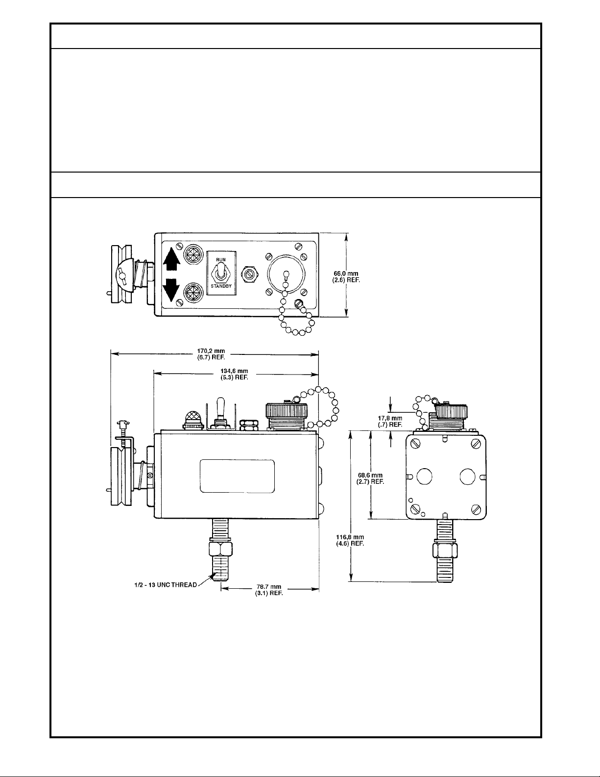
DIMENSIONS
See the Dimensions Drawing.
BLN-95-8970-4
1304
Dimensions of the MCW102B in Millimeters (inches).
2
Page 3
TECNICAL DATA
(continued)
PERFORMANCE
TEST CONDITIONS
SUPPLY: 14 Vdc or 24 Vdc
GAIN: Maximum (full cw)
RUN/STANDBY SWITCH: Run
TEMPERATURE: 25° C
Shaft rotation measured at end of 4.25 inch long horizontal arm. (Equivalent to a standard 6 inch long sensing
arm trailing at 45°).
MAXIMUM TORQUE
6.0 in-gms required to rotate the shaft from either side of
null to the stop.
NULL CENTERING
With the shaft roll pin centered between the stops,
electrical null will occur within ± .37 inches.
GAIN SETTING
Electrical null will vary .01 inch maximum from maximum
to minimum gain.
MAXIMUM TEMPERATURE NULL SHIFT
.15 inch vertical deflection over the range from 0° to 50°
C (32° to 122° F). A larger null shift may occur over a
greater temperature span. It is recommended that the
user re-null the MCW102B each morning before using.
See the Adjustment section.
PROPORTIONAL BAND
.30 ± .10 inches
INDICATOR LAMPS DEADBAND (MCW102B)
.05 inches maximum
GAIN SETTING EFFECT ON INDICATOR NULL
.01 maximum from maximum to minimum gain. Indicator and valve null track within less than .01 inches
equivalent at the grade sensing point.
CENTERING
Lamps will come on within .04 inches of each other.
NULL POINT STABILITY
Changes in supply voltage from 11 to 15 Vdc will not
change the null point more than .02 inches.
REMOTE SETPOINT/STEERING FEEDBACK PHASING
With the feedback potentiometer turned fully clockwise
(toward the positive end of the potentiometer), the
MCW102B shaft must rotate clockwise to null facing the
hub.
NULL SETTING WITH REMOTE SETPOINT/STEERING
FEEDBACK
With the feedback potentiometer at either end, the
MCW102B will null within 15° of the null point without
remote input.
PHASING
Facing the hub with the lamps up, a clockwise shaft
rotation will make pin F positive with respect to pin E.
The right lamp will come on. If desirable, this phasing
can be reversed. Model MCW102B1020 has reverse
phasing.
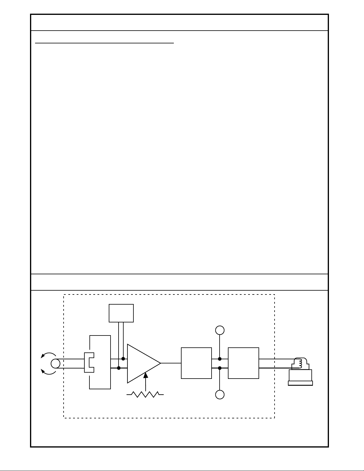
BLOCK DIAGRAM
OSCILLATOR
HALL EFFECT
SENSOR
GAIN LIGHT
RUN/STANDBY SWITCH
On Standby, output will be 0 ± 1 mA.
LIGHT
POWER
DRIVE
RUN
STANDBY
MCW102
KVF
FLOW CONTROL
SERVOVALVE
(TYPICAL)
1740
3
BLN-95-8970-4
Page 4

THEORY OF OPERATION
The MCW102B Proportional Rotary Position Controller consists of two stages: a sensor input and an amplifying/
controlling section. See the MCW102B Block Diagram. The
sensor input section accepts steering or grade information
through either a right angle or straight tube follower. Right
angle followers are used to sense grade and are either
tubular (for stringlines) or skate and ski (for firm reference
surfaces). Straight followers are used to sense a steering
path and are tubular. As the reference is raised or lowered left or right for steering - the hub shaft is rotated so that the
follower maintains contact.
As the hub shaft turns, it rotates a U-shaped magnet that is
attached inside the device housing. A Hall Effect sensor is
mounted to the housing between the poles of the magnet, and
as the angle of the flux lines passing through the Hall sensor
changes with the follower, the voltage from the sensor varies.
The output voltage is approximately proportional to the angle
of rotation over the sensing range.
The amplifying/controlling section of the MCW102B compares the voltage output of the Hall sensor against the
midpoint of a 200 Hz square wave that alternately puts a high
voltage on one side and then the other of the output pins to
a proportional valve. See the Typical Output Signal diagram.
In steering applications, the square wave midpoint varies up
and down in response to the ACX104C Feedback Sensor
signal. When the midpoint of the square wave equals the Hall
null output voltage, the duration of the signals alternately
placed on pins E and F is equal, and the valve remains
centered due to the high frequency of the cycling. But if the
two voltages become non-symmetrical the voltage duration
becomes biased towards the appropriate side of the valve.
The appropriate incandescent light will fire when the vertical
deviation from the sensor exceeds ± .025 inches vertical
deflection from null.
TYPICAL OUTPUT SIGNAL
PIN E
PIN F
PULSE RELATION AT NULL
PIN E
PIN F
PULSE DRIVING TOWARD PIN E
PIN E
PIN F
PULSE DRIVING TOWARD PIN F
+6
+6
+6
+6
+6
+6
966
MOUNTING
Determine the mounting location, and drill a 9/16-inch (14
mm) hole for the mounting stud. Remove the nut and
lockwasher. Mount the MCW102B with the shaft horizontal.
Tighten the nut against the lockwasher, but not too tightly,
since it must be loosened in the adjustment procedure.
Attach the appropriate follower to the hub. Note the guide
hole location and direction of travel. Guide holes in the
mounting bracket for the grade/steering followers, part number KG07002, are located as shown in the Guide Hole
Identification diagram. Part number KG07002 is only used
for steering applications.
After the follower has been installed, adjust the spring on the
hub so the follower exerts a very light pressure on the
stringline or reference surface.
A skate assembly, part number KG06001, and ski assembly,
part number KG02001, may be used with the right angle
follower, part number KG04003 when a firm reference surface is used. When using these devices, hub spring tension
is comparatively unimportant.
GUIDE HOLE IDENTIFICATION
BREAKAWAY JOINT
STEERING
LEFT HUB
GRADE
RIGHT
1
HUB
THE RIGHT HUB IS DEFINED AS THE ONE WITH
1
THE SPRING BIAS ADJUSTMENT THUMBSCREW
STEERING
RIGHT HUB
LEFT
HUB
1
952B
BLN-95-8970-4
4
Page 5

WIRING
All wiring connections are made through an MS Connector
located on the end of the front panel of the device. A two-foot
coiled cable that extends to ten feet is available with plugs for
easy connection and removal. A straight plug is provided on
one end and a right angle plug on the other (part number
CONNECTION DIAGRAM
MCW102B
PROPORTIONAL ROTARY POSITION CONTROLLER
KW01013
CABLE ASS'Y
MATING CABLE
KW02001
KW01013), or two straight plugs (part number KW01014).
Use an MS3102A18-1P connector (part number K03989) on
the machine for cable connections. See the Connection
diagram.
K04825
TERMINAL BLOCK
A
B
C
D
E
F
G
H
C
ON
+12 VOLTS
OFF
KVF
FLOW CONTROL
SERVOVALVE
MANIFOLD
KK03509
ADJUSTMENT
1. Place the Run/Standby switch on Standby.
2. Loosen the locknut on the front of the housing, which
captures the gain adjustment potentiometer.
3. Turn the deadband potentiometer fully clockwise to
maximum gain.
4. Apply electrical power to the system. Hydraulic power is
not necessary at this time.
5. With the equipment at the correct grade position, adjust
the vertical position of the MCW102B until an equivalent
angular deflection causes the lamps to fire. Lock the
controller in place.
B
A
STEERING CYLINDER
1621A
6. Turn the potentiometer back approximately 1/4 turn.
7. Turn on the hydraulic power and place the Run/Standby
switch on Run.
8. Observe the response of the machine. If it oscillates
when returning to null, turn the potentiometer counterclockwise. If the machine slowly approaches null but
stops short, turn the potentiometer clockwise.
9. Tighten the locknut to hold the gain adjustment potentiometer.
5
BLN-95-8970-4
Page 6

TROUBLESHOOTING
Keep the following facts in mind while troubleshooting
the system:
• The lights will indicate deviations whenever power is
applied to the MCW102B, regardless of the Run/
Standby switch position.
• In the Run position, amplifier output is connected to the
valve. In the Standby position, it is not.
• If the gain potentiometer is turned fully counterclockwise
(minimum gain), a larger deviation will be needed to
command an output to the proportional valve.
• Preliminary checks should include examination of the
cables and leads for damaged or broken wire. Examine
areas where shorting may occur. Check the power
supply to be sure it is greater than 11 volts.
ORDERING INFORMATION
SPECIFY
1. Time proportional or proportional output
2. Valve load to be driven
3. Accessories
4. Service parts
ACCESSORIES
1. KG07002, Steering Follower
Straight tubular follower, 20.1 inches long overall with
breakaway joint. For steering only.
2. KG04003, Right Angle Grade Follower
With breakaway joint. For grade applications only.
Follows a stringline. Also used with skate assembly, or
skate and ski assembly for following hard reference
surface.
1. Check for free rotation, proper spring loading and tightness in all sensor grid parts.
2. Unhook the MCW102B cables and manually operate
the valves to check for correct operations. Re-connect
the cables.
3. Check the lights when the controller is in the Standby
mode. Vary the machine position manually and note the
indication. One light and then the other should glow as
the conditions are reversed.
4. If another controller is available, set it on the same
surface as the other and plug the MS connector into the
replacement unit. Check system operation. If the
problem disappears, the controller is defective. Substitute the replacement and return the old device as
outlined in the Ordering Information.
4. KG06001, Skate Assembly
For grade applications. Used with right angle grade
follower (part number K09274) on hard reference surface.
5. KG02001, Ski Assembly
For grade applications. Used with right angle grade
follower (part number K09274), and skate assembly
(part number KG06001) on hard reference surface.
6. KW01013, Cable Assembly
Two foot coiled cable that extends to ten feet. Has right
angle connector on one end and straight connector on
the other to make connections between the MCW102B
and Bendix Type No. MS3102A18-1P plug (part number K03989).
7. K00702 Lens (service part)
3. K09274, Right Angle Grade Follower Less Sensing Arm
For grade applications utilizing the skate and/or skate
and ski assembly. Same as part number KG04003
above, but without the sensing arm and breakaway joint.
ORDER NUMBER INPUT ELECTRICAL DESCRIPTION DRIVES
MCW102B1004 12 Vdc No Remote Setpoint/Steering Connections KVF
MCW102B1020 12 Vdc Pins C/D Common For Remote Setpoint or KVF
MCW102B1038 12 Vdc Pins C/D Common For Remote Setpoint or V7509
MCW102B1046 12 Vdc No Remote Setpoint/Steering Connections V7509
MCW102B1053 24 Vdc Lamp Phasing Reversed KVF
Requires ± 20° Shaft Rotation To Re-null,
Pins C/D Common For Remote Setpoint or
MCW102B1061 12 Vdc Pins C(+) and D(-) Are Separate Remote KVF
Setpoints or Steering Feedback Connections
MCW102B1085 24 Vdc Pins C/D Common For Remote Setpoint or KVF
BLN-95-8970-4
8. K03891 Lamp (service part)
Steering Feedback
Steering Feedback
Steering Feedback
Steering Feedback
6
Page 7

CUSTOMER SERVICE
NORTH AMERICA
ORDER FROM
Danfoss (US) Company
Customer Service Department
3500 Annapolis Lane North
Minneapolis, Minnesota 55447
Phone: (763) 509-2084
Fax: (763) 559-0108
DEVICE REPAIR
For devices in need of repair or evaluation, include a
description of the problem and what work you believe
needs to be done, along with your name, address and
telephone number.
RETURN TO
Danfoss (US) Company
Return Goods Department
3500 Annapolis Lane North
Minneapolis, Minnesota 55447
EUROPE
ORDER FROM
Danfoss (Neumünster) GmbH & Co.
Order Entry Department
Krokamp 35
Postfach 2460
D-24531 Neumünster
Germany
Phone: 49-4321-8710
Fax: 49-4321-871-184
7
BLN-95-8970-4
 Loading...