

Page 1
DESCRIPTION
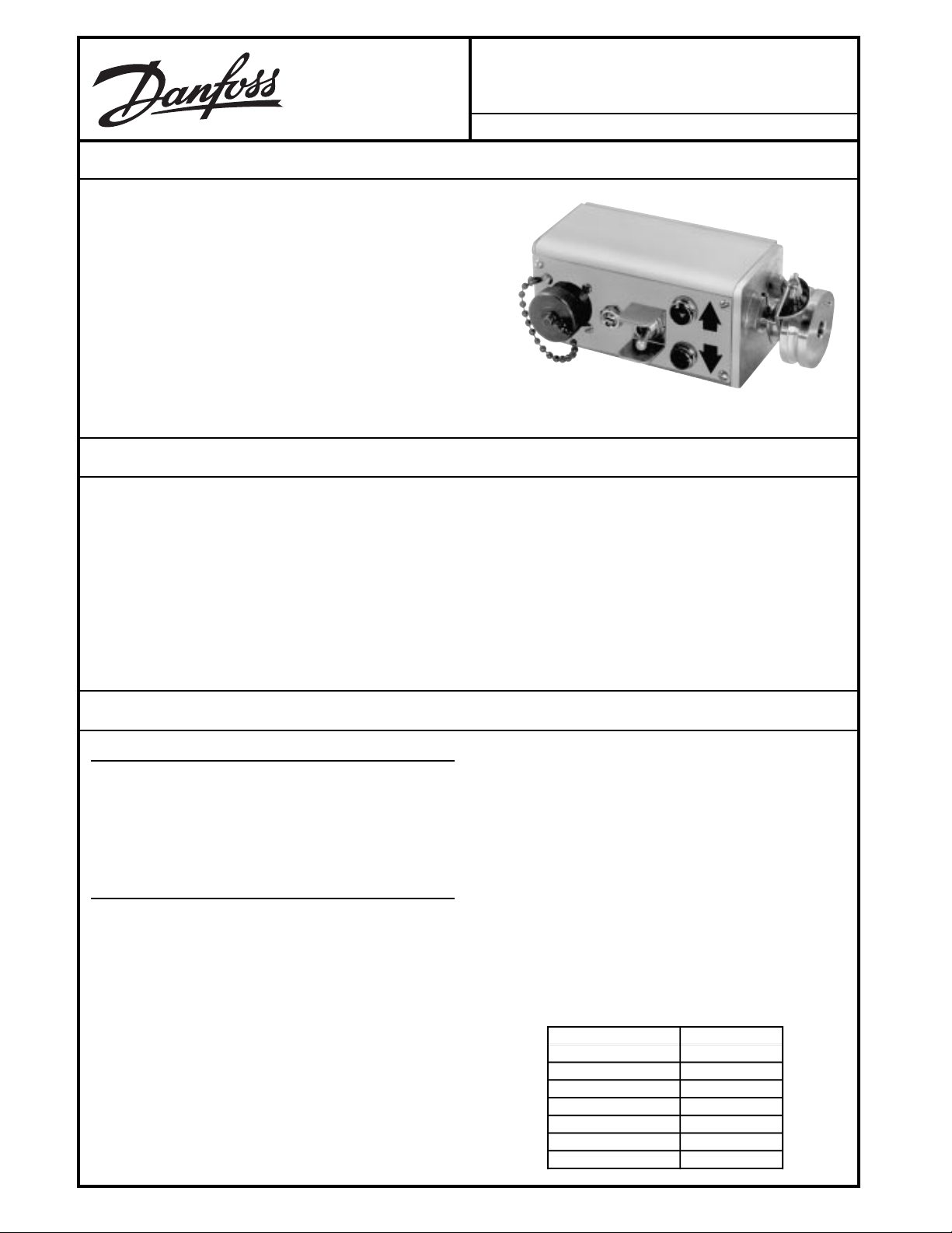
The MCW102A and MCW102C Time Proportional Rotary Position Controllers provide automatic grade control on paving,
curbing and planing machines. The Controller uses a follower arm
riding on a stringline or a ski riding on the prepared surface as a
grade reference. The controllers activate solenoid valves to
position a screed, form cutting drum, or steer cylinder.
The MCW102A and C are time proportional devices having valve
on - time proportional to grade error. This feature causes the
output to the solenoid to be on a greater percentage of the time for
larger grade deviations, allowing greater sensitivity to grade
deviations than would otherwise be possible. The “A” model is
ground-side switched and the “C” model is high-side switched.
FEATURES
MCW102A,C
Time Proportional Rotary Position Controller
BLN-95-9048 Issued: March 1995
• Non-contacting sensing element for long life
• Fully burned-in components for added reliability
• Bright up/down lights for easy nulling
• Adjustable deadband sensitivity
• Run/Standby switch for manual or automatic control
• Reverse polarity and short circuit protection
ORDERING INFORMATION
SPECIFY
1. Model Number MCW102A1005 (ground-side switching)
Model Number MCW102C1002 (high-side switching)
2. Valve load to be driven
3. Accessories
4. Service parts
ACCESSORIES
1. KG04003, Right Angle Grade Follower
With breakaway joint. For grade applications only.
Follows a stringline. Also used with skate assembly, or
skate and ski assembly for following hard reference
surface.
2. K09274, Right Angle Grade Follower Less Sensing Arm
For grade applications utilizing the skate and/or skate
and ski assembly. Same as part number KG04003
above, but without the sensing arm and breakaway joint.
3. KG06001, Skate Assembly
For grade applications. Used with right angle grade
follower (part number K09274) on hard reference sur-
face.
• Rugged aluminum housing
• Withstands high vibration and shock
• Moisture and corrosion resistant
• Easy to mount
• Adjustable tracking force
4. KG02001, Ski Assembly
For grade applications. Used with right angle grade
follower (part number K09274), and skate assembly
(part number KG06001) on hard reference surface.
5. Cable Assemblies:
KW01013 – Two-foot coiled cable that extends to ten
feet. Has right angle connector on one end and straight
connector on the other to make connections between
the MCW102 and Bendix Type No. MS3102A18-1P
plug (part number K03989).
KW01035 – Two-foot coiled cable that extends to ten
feet. Has right angle connector on one end and straight
connector on the other to make connections between
the MCW102A and the paving machine bulkhead.
STRAIGHT 90°
CONNECTOR CONNECTOR
AA
BB
CE
DF
EC
FD
© Danfoss, 2013-09 BLN-95-9048 1
.
.
Page 2
ORDERING INFORMATION
KW01015 – Two-foot coiled cable that extends to ten
feet. Has two straight connectors to make connections
between the MCW102C and the paving machine bulk-
head.
KW01034 – Two-foot coil cable that extends to ten feet,
has right angle connector on one end and straight
connector on the other end to make connections between the MCW101 and paving machine bulkhead.
STRAIGHT 90°
CONNECTOR CONNECTOR
AA
BB
(continued)
FE
EF
6. K00702 Lens (service part)
7. K03891 Lamp (service part)
TECHNICAL DATA
ELECTRICAL
SUPPLY VOLTAGE
12 volts
0.5 amps
Does not include output current to load.
MAXIMUM OUTPUT CURRENT @ 14 VDC SUPPLY
2.5 amp with 5 ohm load
The MCW102A has ground-side switching
The MCW102C has high-side switching
MAXIMUM REVERSED POLARITY VOLTAGE
50 Vdc for 5 minutes
SHORT CIRCUIT PROTECTION
The controllers are protected against short circuits
across the valve coil as well as shorts between the
outputs and ground. A short circuit is defined as 1 ohm
maximum resistance for 5 minutes maximum.
LOAD DUMP
Protected against load dump per SAE J2.20.97
MECHANICAL
Physical stops limit the rotation to approximately ± 23° from
null.
ENVIRONMENTAL
OPERATING TEMPERATURE
-18° to 65° C (0° to 150° F)
STORAGE TEMPERATURE
-30° to 65° C (-22° to 150° F)
HUMIDITY
After being placed in a controlled atmosphere of 95%
humidity at 38° C for 10 days, the controller will perform
within specification limits.
RAIN
The controller will withstand exposure to a 15 minute
shower with cold water after reaching the maximum
storage temperature.
VIBRATION
Withstands a vibration test designed for mobile equipment controls consisting of two parts:
1. Cycling from 5 to 2000 Hz in each of the three axes.
2. Resonance dwell for one million cycles for each
resonant point in each of the three axes.
Run from 1 g to 8 g’s. Acceleration level varies with
frequency.
SHOCK
50 g for 11 milliseconds. Three shocks in both directions
of the three mutually perpendicular axes for a total of 18
shocks.
DIMENSIONS
See the Dimensions Drawing.
2
BLN-95-9048
Page 3

DIMENSIONS
Dimensions of the MCW102A, C in Millimeters (Inches).
1304
3
BLN-95-9048
Page 4
TECHNICAL DATA
(continued)
PERFORMANCE
TEST CONDITIONS
SUPPLY: 14 Vdc
LOAD: 5 ohm minimum
DEADBAND: Maximum (full ccw)
RUN/STANDBY SWITCH: Run
TEMPERATURE: 25° C
Shaft rotation measured at end of 4.25 inch long horizontal arm. (Equivalent to a standard 6 inch long sensing
arm trailing at 45°).
MAXIMUM TORQUE
6.0 in-gms required to rotate the shaft from either side of
null to the stop.
NULL CENTERING
With the shaft roll pin centered between the stops,
electrical null will occur within ± 0.37 inches.
MAXIMUM TEMPERATURE NULL SHIFT
0.15 inch vertical deflection over the range from 0° to 50°
C (32° to 122° F). A larger null shift may occur over a
greater temperature span. It is recommended that the
user re-null the Controller each morning before using.
See the Adjustment section.
PHASING
Facing the hub with the lamps up, a clockwise shaft
rotation will make pin F positive with respect to pin E.
The right lamp will come on.
PROPORTIONAL BAND
.33 ± .08 inches
FREQUENCY OF OUTPUT PULSES
MCW102A1005 3 ± 1 Hz
MCW102C1002
MCW102C1011
MCW102A1013 4.5 ± 1 Hz
MINIMUM OUTPUT PULSE WIDTH
MCW102A1005 37 ± 12 ms
MCW102C1002
MCW102C1011
MCW102A1013 50 ± 12 ms
DEADBAND ADJUSTMENT
Overlap to a minimum of 0.12 inches
NULL POINT STABILITY
Changes in supply voltage from 11 to 15 Vdc will not
change the null point more than 0.02 inches.
RUN/STANDBY SWITCH
On Standby, output will be 0 ± 1 mA.
THEORY OF OPERATION
Both the MCW102A and MCW102C Controllers consist of
two stages: a sensor input and an amplifying/controlling
section. See the MCW102A and MCW102C Block Diagrams.
The sensor input section accepts steering or grade information through either a right angle or straight tube follower.
Right angle followers are used to sense grade and are either
tubular (for stringlines) or skate and ski (for firm reference
surfaces). As the reference is raised or lowered the hub shaft
is rotated so that the follower maintains contact.
As the hub shaft turns, it rotates a U-shaped magnet that is
attached inside the device housing. A non-contact sensor is
mounted to the housing between the poles of the magnet,
and as the angle of the flux lines passing through the sensor
changes with the follower, the voltage from the sensor varies.
The timed output voltage is proportional to the angle of
rotation over the sensing range.
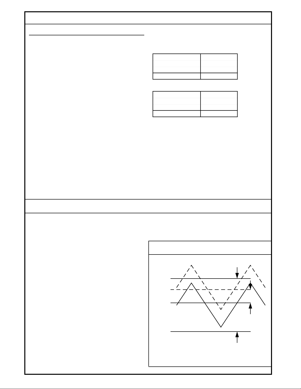
The amplifier sums the error signal from the sensor with a 3
Hz triangular wave to effect the time proportioning. See the
Triangular Wave drawing.
The sum is compared to an upper and lower reference
voltage to drive the output. The separation between the
references (the deadband) is adjustable through a trim potentiometer on the front panel. At minimum sensitivity (wide
deadband), a ± 0.06 inch (six inch grid arm at a 45° angle)
error signal will produce valve drive. At maximum sensitivity
(narrow deadband), both valve drives occur at the peaks of
the triangular waves, even when the system receives no
error signal. Two front-panel incandescent lamps light as the
valve drive trigger is activated.
TRIANGULAR WAVE
DEADBAND
ADJUST
UP
VALVE
ON
OFF NULL
NULL
ERROR
SIGNAL
DOWN
VALVE
ON
1150A
Triangular Wave Summed With Error Voltage In Null
(Solid Line) And Off Null (Broken Line) Conditions.
4
BLN-95-9048
Page 5

MCW102A BLOCK DIAGRAM (Ground Side Switching)
3 Hz
V
t
+
∑
+
V
t
HALL EFFECT
SENSOR
VOLTAGE
FUSE
-+
BATTERY
REGULATOR
V
V
t
t
MCW102C BLOCK DIAGRAM (High Side Switching)
3 Hz
V
t
DEADBAND
POTENTIOMETER
1741
FUSE
BATTERY
+
∑
+
HALL EFFECT
SENSOR
VOLTAGE
REGULATOR
V
-+
t
V
t
DEADBAND
POTENTIOMETER
V
t
1742
5
BLN-95-9048
Page 6

MOUNTING
Determine the mounting location, and drill a 9/16-inch (14
mm) hole for the mounting stud. Remove the nut and
lockwasher. Mount the MCW102 with the shaft horizontal.
Tighten the nut against the lockwasher, but not too tightly,
since it must be loosened in the adjustment procedure.
Attach the appropriate follower to the hub. Note the guide
hole location and direction of travel.
WIRING
All wiring connections are made through a 10 Pin MS Connector located on the end of the front panel of the device. A
two-foot coiled cable that extends to ten feet is available with
plugs for easy connection and removal. A straight plug is
provided on one end and a right angle plug on the other (part
ADJUSTMENT
1. Place the Run/Standby switch on Standby.
2. Loosen deadband potentiometer locknut.
3. Turn the deadband potentiometer fully counterclockwise to minimum deadband.
4. Apply electrical power to the system. Hydraulic power is
not necessary at this time.
After the follower has been installed, adjust the spring on the
hub so the follower exerts a very light pressure on the
stringline or reference surface.
A skate assembly, part number KG06001, and ski assembly,
part number KG02001, may be used with the right angle
follower, part number KG04003 when a firm reference surface is used. When using these devices, hub spring tension
is comparatively unimportant.
number KW01013), or two straight plugs (part number
KW01014). Use an MS3102A18-1P connector (part number
K03989) on the machine for cable connections. See the
MCW102A and MCW102C Connection Diagrams.
6. Turn the potentiometer back approximately 1/4 turn.
7. Turn on the hydraulic power and place the Run/Standby
switch on Run.
8. Observe the response of the machine. If it oscillates
when returning to null, turn the potentiometer clockwise.
If the machine slowly approaches null but stops short,
turn the potentiometer counterclockwise.
5. With the equipment at the correct grade position, adjust
the vertical position of the MCW102 until the lights are
blinking for the same amount of time, or until an equivalent angular deflection causes the lamps to fire. Lock the
controller in place.
TROUBLESHOOTING
Keep the following facts in mind while troubleshooting
the system:
• The lights will indicate deviations whenever power is
applied to the MCW102, regardless of the Run/Standby
switch position.
• In the Run position, amplifier output is connected to the
solenoid. In the Standby position, it is not.
• If the deadband potentiometer is turned fully clockwise
(maximum deadband), a large deviation will be needed
to command an output to the solenoid.
• Preliminary checks should include examination of the
cables and leads for damaged or broken wire. Examine
areas where shorting may occur. Check the power
supply to be sure it is greater than 11 volts.
9. Tighten locknut on deadband potentiometer.
1. Check for free rotation, proper spring loading and tightness in all sensor grid parts.
2. Unhook the MCW102 cables and manually operate the
solenoids to check for correct operations. Re-connect
the cables.
3. Check the lights when the controller is in the Standby
mode. Vary the machine position manually and note the
indication. One light and then the other should glow as
the conditions are reversed.
4. If another controller is available, set it on the same
surface as the other and plug the MS connector into the
replacement unit. Check system operation. If the
problem disappears, the controller is defective. Substitute the replacement and return the old device as
outlined in the Ordering Information.
6
BLN-95-9048
Page 7

MCW102A CONNECTION DIAGRAM
MCQ/Q625
REMOTE SETPOINT
ABCD
A
B
C
D
E
F
AMPLIFIER
MCW101B1006
SLOPE CONTROLLER
A
B
LEFT
SIDE
C
KW01034 SLOPE CABLE
D
RUN
STANDBY
(NO LEFT/RIGHT SWITCH)
ON
OFF
UP
DOWN
+ 12 V
5A
LEFT
SOLENOID
VALVE
+12 VDC
AMPLIFIER
STANDBY
MCW102A1005
GRADE CONTROLLER
HUB LEFT
ON
5A
RIGHT
SOLENOID
VALVE
OFF
UP
DOWN
RUN
+12 V
UP
DOWN
RIGHT
SIDE
A
B
C
D
E
F
A
B
C
D
KW01035 GRADE CABLE
E
F
JOG
UP
DOWN
PAVING MACHINE
UP
DOWN
JOG
E
F
MCW102A Used in a Grade and Slope System with Ground-Side Switching and Four Pin Machine Connection.
7
BLN-95-9048
1743
Page 8

MCW102C CONNECTION DIAGRAM
Q625A1136
REMOTE SETPOINT
ABCD
A
AMP LIFIE R
AMP LIFIE R
A
RUN
STANDBY
MCW101A1023
SLOP E CO NT ROLLER
A
B
C
D
DOWN
+12 V
GRADE
SLOPE
ON
OFF
UP
UP
DOWN
B
C
D
E
F
JOG
LEFT
SOLENOID
VALVES
KW01015
CABLE
5A
+12 VDC
RUN
STANDBY
MCW102C1002
GRADE CONT ROLLER
HUB TOWARD
OUTSIDE
ON
5A
RIGHT
SOLENOID
VALVES
JOG
OFF
UP
DOWN
UP
DOWN
+12 V
B
C
D
E
F
KW01015
CABLE
A
B
C
D
E
F
E
F
PAVI NG MACHINE
MCW102C Used in a Grade and Slope System with High-Side Switching and Six Pin Machine Connection.
8
1744
BLN-95-9048
Page 9

CUSTOMER SERVICE
NORTH AMERICA
ORDER FROM
Danfoss (US) Company
Customer Service Department
3500 Annapolis Lane North
Minneapolis, Minnesota 55447
Phone: (763) 509-2084
Fax: (763) 559-0108
DEVICE REPAIR
For devices in need of repair, include a description of the
problem, a copy of the purchase order and your name,
address and telephone number.
RETURN TO
Danfoss (US) Company
Return Goods Department
3500 Annapolis Lane North
Minneapolis, Minnesota 55447
EUROPE
ORDER FROM
Danfoss (Neumünster) GmbH & Co.
Order Entry Department
Krokamp 35
Postfach 2460
D-24531 Neumünster
Germany
Phone: 49-4321-8710
Fax: 49-4321-871-184
9
BLN-95-9048
 Loading...