

Page 1
MCW100C, MCW100E
Time Proportional Rotary Position Controller
BLN-95-9013-1Issued: March 1995
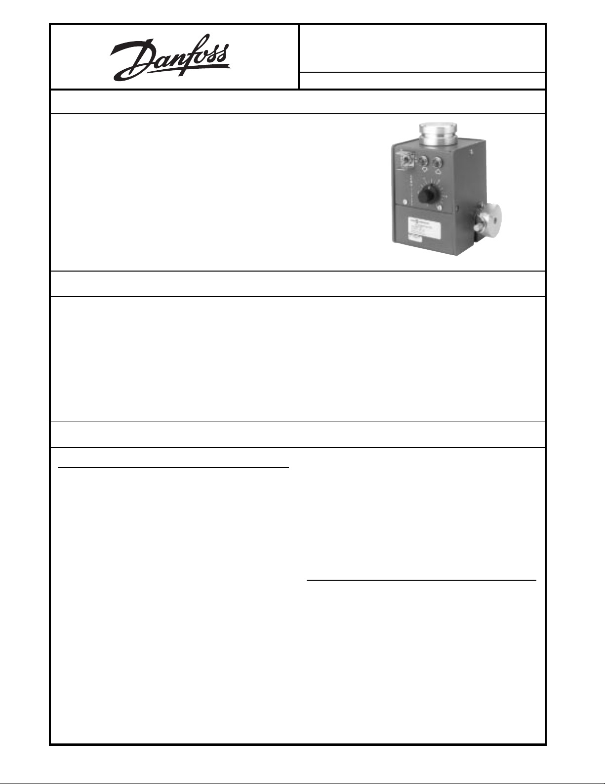
DESCRIPTION
The MCW100C,E Time Proportional Rotary Position Controller provides
automatic grade or steering control of paving, trenching and curbing machines. The Controller uses a wand follower to sense the grade level or
steering command from a stringline or flat surface.
Two modules are housed in the case of the Controller. The grade sensing
module electromagnetically measures the machine's deviation from a grade
reference. The amplifier module receives the signal from the sensor module
and produces a voltage output to drive solenoid valves which, on a typical
paving machine, operate lift cylinders. Within the amplifier's proportional
band, the percent of time the output is on is proportional to the grade error. The
MCW100C,E may be used together with the MCW101 Time Proportional
Level Controller to control both parameters simultaneously.
FEATURES
• May be mounted on either side of machine
• Adjustable tracking force
• Dual UP/DOWN lamps show deviation from setpoint in
RUN and STANDBY modes
• Adjustable deadband varies sensitivity
• Run/Standby switch permits operator to switch to
manual control
ORDERING INFORMATION
ACCESSORIES
1. STEERING FOLLOWER
Straight tubular follower, 16 inches long overall with
breakaway joint. For steering only. Part number
KG07002.
2. RIGHT ANGLE GRADE FOLLOWER
With breakaway joint. For grade applications only. Follows a stringline. Also used with skate assembly, or
skate and ski assembly for following hard reference
surface. Part number KG04003.
3. RIGHT ANGLE GRADE FOLLOWER LESS SENSING
ARM
For grade applications utilizing the skate and/or skate
and ski assemblies. Same as Part number KG04003,
above, but without the sensing arm and breakaway joint.
Part number K09274.
4. SKATE ASSEMBLY
For grade applications. Use with right angle grade follower (Part number K09274) on hard reference surface
Part number KG06001.
5. SKI ASSEMBLY
For grade applications. Used with right angle grade
• Flexible joint on follower prevents breakage
• Rugged aluminum housing
• 12 Vdc or 24 Vdc supply voltage
• Reverse polarity and short circuit protected
• Moisture and corrosion resistant
• Withstands vibration and shock
follower (Part number K09274), and skate assembly
(Part number KG06001) on hard reference surface. Part
number KG02001.
6. CABLE ASSEMBLY
KW01015 two-foot coiled cable that extends to ten feet
(3 meters). Has right angle connector on one end
and straight connector on the other end to make
connections between the MCW100C,E and Bendix
Type No. MS3102A18-1P plug. (Part number K03989).
SERVICE PARTS
1. AMPLIFIER MODULE
Removable modular amplifier can be exchanged with
other voltage compatible grade controllers:
Part Number K02910 (12 volt, MCW100C)
K02911 (24 volt, MCW100C)
K10654 (12 volt, MCW100E)
K10655 (24 volt, MCW100E)
2. K00702 Lens
3. K00706 Lamp (12 volt models)
K00707 Lamp (24 volt models)
4. K00665 RUN/STANDBY Switch
©Copyright 2001, Danfoss (US) Company.
1
All rights reserved. Contents subject to change.
Page 2
ORDERING INFORMATION (
CONTROLLER SUPPLY VOLTAGE TYPE OF OUTPUT
MCW100C1007 12 Vdc Ground side switching
MCW100C1015 24 Vdc Ground side switching
MCW100E1005 12 Vdc High side switching
MCW100E1013 24 Vdc High side switching
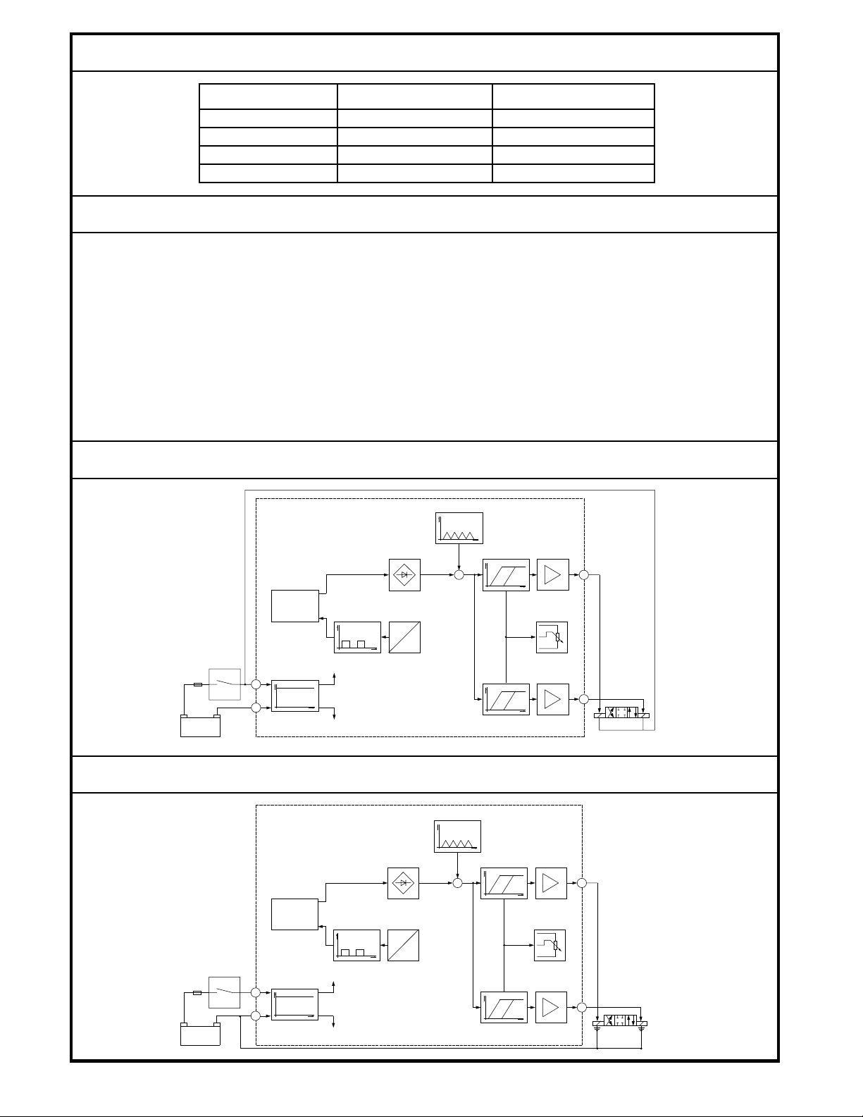
TECHNICAL DATA
continued)
OPERATING VOLTAGE
12 Volt Model: 11 to 15 Vdc
REVERSE POLARITY PROTECTION
200 Vdc, maximum
24 Volt Model: 22 to 30 Vdc
SHORT CIRCUIT PROTECTION
SUPPLY CURRENT
Full, with 0.5 Ω maximum resistance
0.6 A, maximum, not including output current to the valve
TIME PROPORTIONAL OUTPUT FREQUENCY
MAXIMUM VOLTAGE DROP (3 A load current)
f = 3 Hz ± 1 Hz
3.5 Vdc
MINIMUM PULSE WIDTH
CURRENT OUTPUT
t = 37 ms ± 12 ms
3 A, maximum
BLOCK DIAGRAM MCW100C - Ground Side Switching
V
3 Hz
t
+
V
+
Microsyn
-
V
440 Hz
f
V
t
t
potentiometer
Sensitivity
F
+
-
Battery
Voltage regulator
V
t
BLOCK DIAGRAM MCW100E - High Side Switching
V
3 Hz
+
-
+
Microsyn
BLN-95-9013
V
F
+
-
Battery
Voltage regulator
V
t
440 Hz
f
V
t
2
V
t
1812
t
V
t
Sensitivity
potentiometer
V
t
1842
Page 3
THEORY OF OPERATION
The MCW100C,E Time Proportional Grade Controller consists of a grade-sensing transducer and an amplifier. The
sensor and amplifier are housed in a single aluminum channel and can be removed easily for repair or replacement.
They are connected with a MS-connector.
Steering and grade information is sent to the Controller
through either a right angle or straight tube follower. Right
angle followers are used to sense grade and are either
tubular (for stringlines) or skate and ski (for firm reference
surfaces). Straight followers are used to sense a steering
path and are tubular. As the reference is raised or lowered left or right for steering - the transducer shaft is rotated so that
the follower maintains contact.
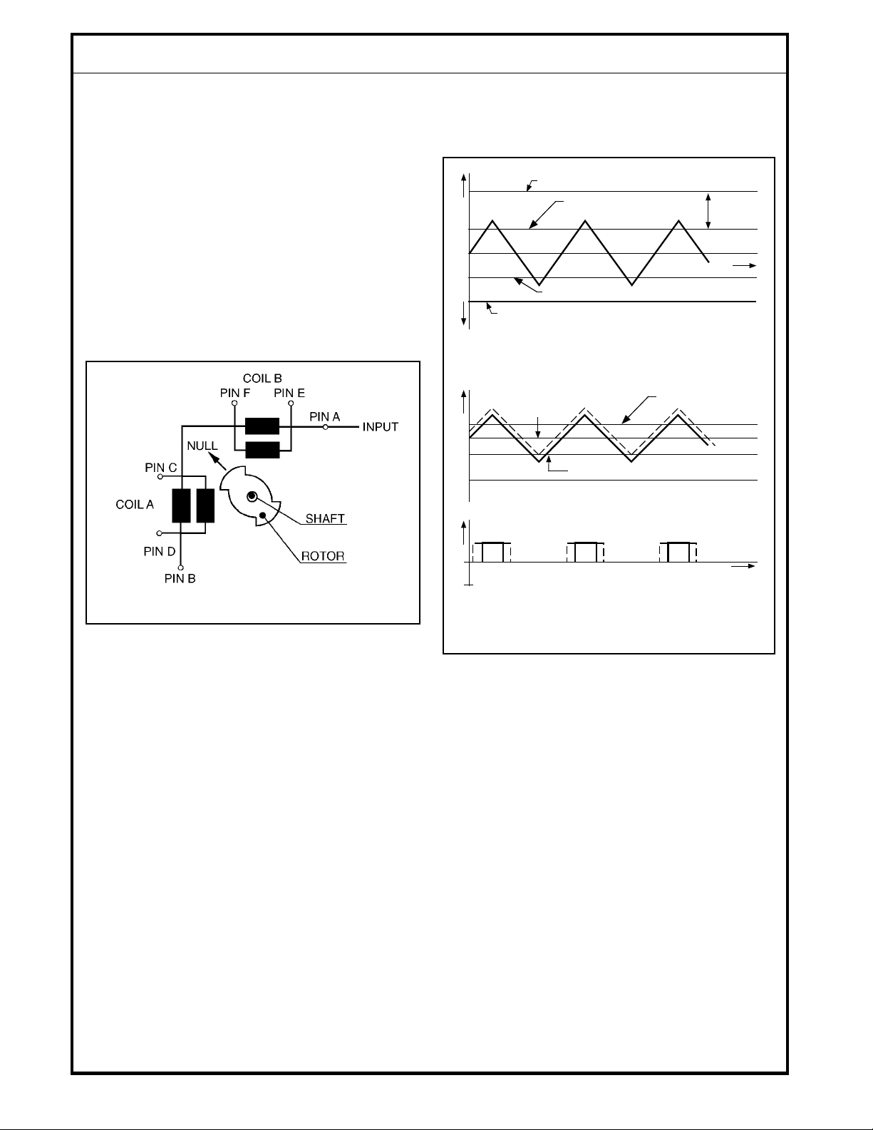
The transducer transforms this shaft rotation into an electrical
signal through the rotor/stator interaction. (See Figure 1.)
The secondary voltages are demodulated in the amplifier to
power a bridge network. A 3 Hz triangular wave is summed
with the error signal, defined by the difference between the
voltages, to effect the time proportioning. (See Figure 2.)
min. sensitivity
max. sensitivity
0
max. sensitivity
min. sensitivity
no output signal to the solenoid valve
0
error
upper trigger level
adjust
sensitivity
t
lower trigger level
upper trigger level
1814
Figure 1.
A 440 Hz square wave from the amplifier is applied to the
primaries of coils A and B. The stator position with respect to
the rotor determines the voltages from the coil secondaries.
output signal to the solenoid valve
0
Figure 2.
t
1815
The sum is compared to a reference voltage by two Schmitt
triggers, which drive the solenoids. As the slope sensor
rotates, the triangular wave moves up or down with respect
to zero error signal. When the triangle crosses the upper or
lower trigger level the output signal is turned on. When a
Remote Setpoint is used, the difference between the voltages is kept proportional to the commanded slope. The
separation between the reference voltages (the deadband)
is adjustable through a trim potentiometer in the front panel.
At minimum sensitivity (maximum deadband), a 0.4% slope
error signal will fire the triggers. At maximum sensitivity
(minimum deadband), both triggers will fire alternately at the
peaks of the triangular waves, even when the system is level.
The sensitivity adjustment controls the difference between
the upper and lower trigger from overlap to 0.5% slope.
3
BLN-95-9013
Page 4
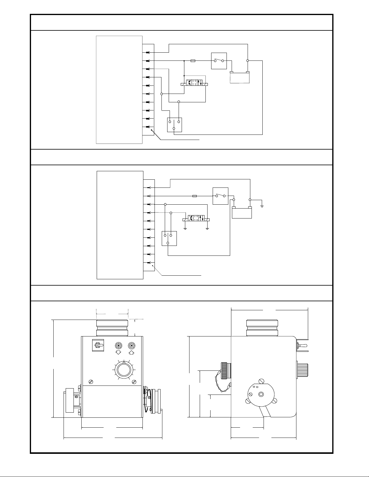
CONNECTION DIAGRAM MCW100C - Ground Side Switching
A
B
C
D
E
F
DOWN
G
H
I
DOWN
J
F
5A
BATTERY
UP
JOG
UP
-+
MS-CONNECTOR, 10-PIN
CONNECTION DIAGRAM MCW100E - High Side Switching
A
B
C
F
5A
D
E
F
G
H
DOWN UP
JOG
DOWNUP
I
J
MS-CONNECTOR, 10-PIN
DIMENSIONS
63,5
(2.5)
31,8
(1.25)
S
T
A
O
N
N
D
B
Y
46
S
190,5
(7.5)
E
N
S
I
T
2
I
V
I
T
Y
8
158,8
(6.25)
86,6
(3.4)
+
BATTERY
1816
-
1817
136,7
(5.44)
BLN-95-9013
117,1
(4.61)
188
(7.4)
39,4
(1.55)
Dimensions in Millimeters (Inches)
4
39,1
(1.54)
114
(4.5)
1818
Page 5

INSTALLATION - LOCATION
The MCW100C,E can be mounted on either side of the
machine, oriented according to the location of the reference
surface or stringline. It may be used with a right angle grade
follower, Part number KG04003, or straight tubular follower,
Part number KG07002.
The right angle follower may be attached to the MCW100C,E
hub horizontally, at a 45° angle downward, or at a 45°
upward. (See Figure 3.) The flat on the hub should be parallel
to the grade reference.
Figure 3.
1825
The follower may be attached at a 45° angle upward. (See
Figure 5.) and the follower should be positioned toward the
operator panel.
Figure 5.
1827
When the straight tubular follower is used for steering control
(see Figure 6), the MCW100C,E hub should be directly
above the stringline.
Note: When the right angle follower is
used, the transducer shaft must be mounted perpendicular
to the direction of travel. When the straight tubular follower is
used, the transducer shaft must be parallel with the direction
of travel.
The follower may be attached at a 45° angle downward.
(See Figure 4.)
Figure 4.
1826
Figure 6.
5
1828
BLN-95-9013
Page 6

INSTALLATION - MOUNTING
Attach the appropriate follower to the hub. Note the guide
hole location, and direction of travel. Guide holes in the
mounting bracket for the steering follower, Part number
KG07002, are located as shown (see Figure 7). The follower
may be attached to either hub. The right angle follower, Part
number KG04003, is used for grade applications.
BREAKAWAY JOINT
STEERING
LEFT HUB
GRADE
RIGHT
1
HUB
THE RIGHT HUB IS DEFINED AS THE ONE WITH
1
THE SPRING BIAS ADJUSTMENT THUMBSCREW
STEERING
RIGHT HUB
LEFT
HUB
1
952B
Figure 7.
A skate assembly (Part number KG06001) and ski assembly
(Part number KG02001) may be used with the right angle
follower (Part number KG04003) when a firm reference
surface is used. (See Figures 8 and 9.)
After the follower has been installed, adjust the spring on the
hub so the follower exerts a very light pressure on the
stringline or reference surface. Note that the flat of the hub is
parallel to the top of the case when the MCW100C,E is at null
position.
Figure 8.
1829
BLN-95-9013
Figure 9.
951A
6
Page 7

WIRING
All wiring connections are made through an MS connector
located on the back of the unit . Although two connectors are
provided, only the larger, 10-pin connector is used. (See
Figure 1, page 3 of this document.) A two-foot coiled cable
that extends to ten feet is available with plugs for easy
ADJUSTMENT
1. Place the RUN/STANDBY switch on STANDBY.
2. Turn the deadband potentiometer fully counterclockwise to minimum deadband.
3. Apply electrical power to the system. Hydraulic power is
not necessary at this time.
4. With the equipment at the correct grade position, adjust
the position of the MCW100C until the UP/DOWN grade
lights are blinking for the same amount of time. Lock the
controller in place.
5. Move the follower up and down about 1/4" while observing the lights and increase the deadband setting (turn
clockwise) until both lights are off for about 1/16" of
movement. Usually this is about 1/4 turn clockwise.
6. Turn ON the hydraulic power and place RUN/STANDBY
switch on RUN.
7. Introduce a grade error into the system by either using
the machine JOG switch or by pushing down on the
follower.
removal, A straight plug is provided on one end, and a right
angle plug on the other. Order Part number KW01015. Use
Part number MS3102A18-1P (K03989) connector on the
control panel for cable connection.
TROUBLESHOOTING
The Grade Controller will provide extended, trouble-free
operation and should not need servicing under normal
operating conditions. If preliminary investigation of a
system malfunction indicates trouble in the
MCW100C,E the following facts should be kept in mind
to help determine the problem.
1. The lights will indicate deviations in grade whenever
power is applied to the MCW100C,E, regardless of the
Run/Standby switch position.
2. In the Run position, amplifier output is connected to the
solenoid. In the Standby position, it is not.
3. If the deadband potentiometer is turned fully clockwise
(maximum deadband), a large deviation will be needed
to command an output to the solenoid.
4. Preliminary checks should include examination of the
cables and leads for damaged or broken wire. Examine
areas where shorting may occur. Check the power
supply to be sure it is greater than 11 Vdc (22 Vdc on 24
volt models).
8. Observe the response of the machine. If it oscillates
when returning to null, the deadband is too small. Turn
the potentiometer clockwise. If the machine slowly
approaches null but stops short, the deadband is too
large. Turn the potentiometer counterclockwise.
9. Replace the screw to cover the deadband adjustment.
TROUBLE CHECK
1. With the RUN/STANDBY switch in the STANDBY position, operate the machine JOG switch in both directions
while noting operation of the solenoid. (The JOG switch
is wired separately.) If the solenoid operates in the
wrong direction, reverse the leads on the valve and
recheck. If the solenoid fails to operate, check for voltage
at the JOG switch terminals at the center-off position and
at the solenoid terminals when the switch is activated. If
proper voltage exists, replace the solenoid. If there is no
voltage, check the wiring.
2. Check the lights when the Grade Controller is in the
STANDBY mode. Use the JOG switch to vary machine
position and note the indication. One light and then the
other should glow as the conditions are reversed.
5. Should a bulb need replacement, unscrew the lens from
the panel. The bulb snaps out of its socket, but because
clearances are tight it may be impossible to remove by
hand. If a piece of 5/16" rubber tubing is available, it can
be pushed down over the bulb and pulled back to effect
removal. The replacements are 'DQIRVV PartQXPEHU
K00706 for 12 volt models and K00707 for 249ROW
models. The part can also be purchased through
other vendors as a number 161 (12 9olt) or number 656
(24 9olt) bulb.
3. Disconnect the power and output cable connector from
the MCW100C,E. Check voltage at the socket end of the
cable for at least 11 Vdc between sockets A and B. If
voltage does not exist across A and B, the cable or the
voltage supply is faulty.
4. Check the output voltage from C to ground and D to
ground.
5. If another Grade Controller is available, set it on the
same surface as the other and plug the MS connectors
into the replacement unit. Check system operation. If
the problem disappears, the Controller is defective.
Substitute the replacement controller in its place.
7
BLN-95-9013
Page 8

CUSTOMER SERVICE
NORTH AMERICA
ORDER FROM
Danfoss (US) Company
Customer Service Department
3500 Annapolis Lane North
Minneapolis, Minnesota 55447
Phone: (763) 509-2084
Fax: (763) 559-0108
DEVICE REPAIR
For devices in need of repair or evaluation, include a
description of the problem and what work you believe
needs to be done, along with your name, address and
telephone number.
RETURN TO
Danfoss (US) Company
Return Goods Department
3500 Annapolis Lane North
Minneapolis, Minnesota 55447
EUROPE
ORDER FROM
Danfoss (Neumünster) GmbH & Co.
Order Entry Department
Krokamp 35
Postfach 2460
D-24531 Neumünster
Germany
Phone: 49-4321-8710
Fax: 49-4321-871355
BLN-95-9013
8
 Loading...