

Page 1
Unit Specification
MCV116C3101
Pressure Control Pilot Valve (PCP)
3500 Annapolis Lane North, Minneapolis, MN 55447
Telephone: (763) 509-2084 Telefax: (763
) 559-0108
GENERAL DESCRIPTION
This Pressure Control Pilot (PCP) is an intrinsically safe, torque motor-actuated, double-nozzle flapper valve that produces
a differential output pressure proportional to the applied electrical input signal. It is a single-stage, stand-alone, closed-loop
pressure control valve which uses internal hydraulic pressure reactions to achieve its closed-loop control characteristics. The
PCP contains an arc suppression circuit for use in hazardous areas.
The term "intrinsically safe" refers to a design technique based on limiting energy, electrical and thermal, to a level below that
required to ignite a specific hazardous atmospheric mixture. This device is Factory Mutual certified for use in Class I, II, or III,
Division 1, Group C, D, F, and G hazardous locations as defined by the National Electrical Code, NFPA-70 when used with
approved barriers.
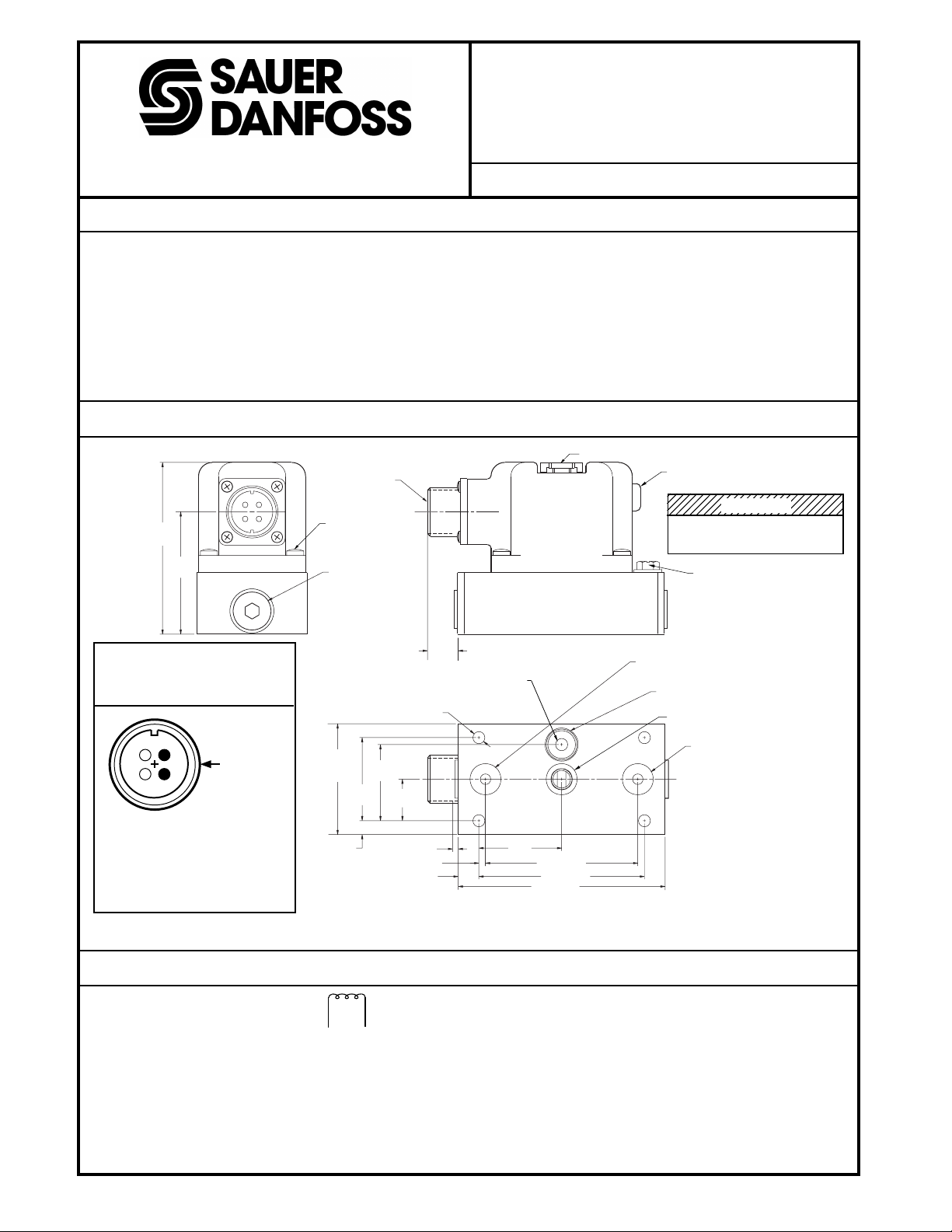
DIMENSIONS
MS CONNECTOR
Intrinsically Safe
ISSUE: 1 DATE: July 1998
MANUAL OPERATOR
NULL ADJUST
ACCESS SCREW
78,7
(3.10)
56,1
(2.21)
ELECTRICAL
CONNECTION
D
A
C
B
Pin Orientation of 4-pin,
° MS Mating Connector.
90
Part No. MS3108E-14S-S
(Sauer-Danfoss Kit
No. K08106).
Active Pins
A, B
2009
DO NOT REMOVE
COVER SCREWS (4)
17,5 DIA (2)
(0.69)
12,7
50,8
(2.00)
MAX
6,3
(0.25)
(1.50)
5,5 (0.217) DIA (4)
34,9
(1.375)
38,1
(0.75)
2,5 (0.10) (2)
(0.50)
19,0
3,0 (0.12)
9,5 (0.38)
REPLACEMENT FILTER
PART NUMBER K08573
38,1
(1.50)
70,1 (2.76)
76,2 (3.00)
95,2 (3.75)
OUTPUT PORT - C1 4,8 (0.19) DIA
12,8 (0.50) O.D. X 1,78 (0.07) O-RING
Dimensions of the MCV116C3101 in Millimeters (Inches).
CAUTION
The cover is filled with 45 cc of 4000 cs
silicone oil. Ensure that minimal oil is lost
when screw is removed.
INTRINSICALLY SAFE DEVICE
ENCLOSURE GROUNDING TERMINAL
PRESSURE PORT THRU FILTER 5,6 (0.22) DIA
12,8 (0.50) O.D. X 1,78 (0.07) O-RING
RETURN PORT 4,8 (0.19) DIA
12,8 (0.50) O.D. X 1,78 (0.07) O-RING
OUTPUT PORT - C2 4,8 (0.19) DIA
12,8 (0.50) O.D. X 1,78 (0.07) O-RING
2023
ELECTRICAL CHARACTERISTICS
• Single coil, coil resistance 23 Ω
• Phasing:
Positive voltage to pin A produces a pressure rise at
output port C1
Positive voltage to pin B produces a pressure rise at
output port C2
• Current/voltage range: up to 190 mA at 4.75 Vdc (linear
range), maximum 275 mA at 7.5 Vdc
K20493 UNIT SPEC
AB
• Pulse Width Modulation (PWM)
The PCP is designed to be controlled from a dc current
source or voltage source. If a PWM signal is used, do not
use a pulse current of more than 120% of that required.
• Scale factor: 1.15 ± 0.1 psid / mA
1 OF 2
©Copyright 2001, Sauer-Danfoss (US) Company.
All rights reserved. Contents subject to change.
Page 2
HYDRAULIC CHARACTERISTICS
• Maximum supply pressure: 1000 psid
Recommended range: 300 - 500 psid
• Maximum return pressure: 200 psid
• Maximum internal leakage: 0.65 gpm
• Maximum linear psid output pressure: 220 psid at 300
psid supply
• Load flow: the output differential flow across a 100 psid
load pressure drop at maximum current: > 30 cim
• Hydraulic Fluid: Petroleum based, other fluids may be
used provided that thy are compatibile with viton and
fluorosilicone seals. Fluid cleanliness is ISO 4406 code
18/15 or better
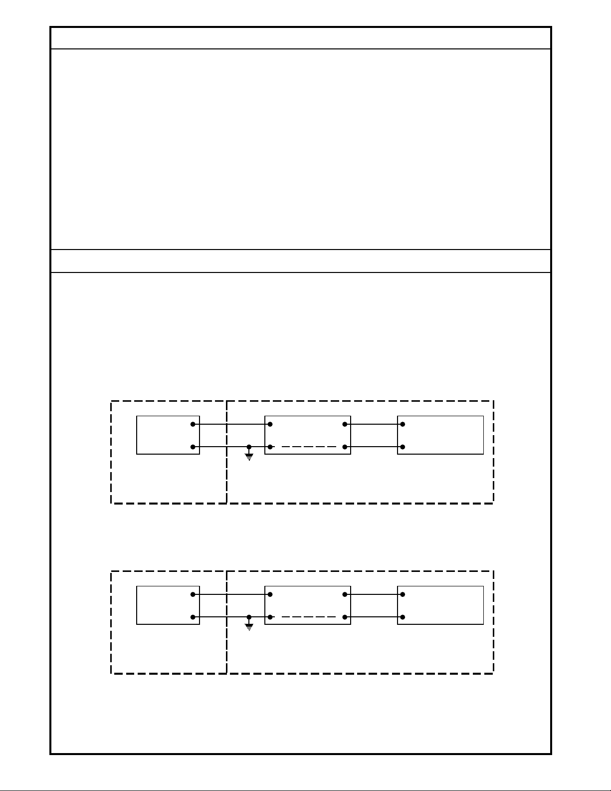
WIRING
A suppression circuit is incorporated in the PCP torque motor
cover but by itself does not insure intrinsic safety. An additional
suppression circuit (Zener barrier) must be connected in
series with the valve coils. The Zener barrier and electrical
controller must be isolated from the hazardous area either
• Hydraulic Null Adjustment: The PCP null adjustment is
sometimes required when configured with the servovalve
(KVF) or applied as a stand-alone. If the PCP null takes
an offset of <15 psid (>15 psid, consult factory) across
C1 and C2 ports it can usually be reestablished to the
original factory setting. To adjust, remove the null access
screw (see Dimensions) and with a 3/32 inch hex head
Allen wrench locate the adjusting screw just inside the
cover. Turn screw in very small increments until the
servovalve neutral is established or C1 and C2 psid is as
close to 0 as possible. When finished, replace access
screw. If the PCP is configured with an Electrical
Displacement Control (EDC) mounted to a pump, never
adjust an EDC neutral using the PCP null adjustment.
EDCs are adjusted at their second stage.
through use of a purge enclosure or mounted in a safe area.
See Dimensions for PCP enclosure grounding. Proper
connection and suggested barrier model numbers are shown
in the connection diagram below .
BIDIRECTIONAL CONTROL, SELECT ONE OF THE FOLLOWING BARRIERS
UNIDIRECTIONAL CONTROL, SELECT ONE OF THE FOLLOWING BARRIERS
Stahl Barrier 9001/02-172-270-10 (12V)
•
Groups A, B, C, D, F and G (maximum voltage ±17.2V)
Stahl Barrier 9001/02-308-230-10 (26V)
•
Groups D, E, F and G (maximum voltage ±31.8V)
A
3
MCV BARRIER
B
HAZARDOUS LOCATION
CLASS I, II, AND III
DIVISION 1
GROUPS C OR D, F AND G
Stahl Barrier 9001/01-158-270-10 (12V)
•
Groups A, B, C, D, F and G (maximum voltage 15.8V)
Stahl Barrier 9001/01-280-280-10 (26V)
•
Groups D, E, F and G (maximum voltage 31.5V)
A
EARTH
GROUND
4
3
MCV BARRIER
B
HAZARDOUS LOCATION
CLASS I, II, AND III
DIVISION 1
GROUPS C OR D, F AND G
EARTH
GROUND
4
(±)1
2
NON-HAZARDOUS LOCATION
(+)1
2
NON-HAZARDOUS LOCATION
CONTROLLER
OUTPUT
CONTROLLER
OUTPUT
1737
NO CHANGES TO THIS DRAWING WITHOUT PRIOR WRITTEN AUTHORIZATION FROM FACTORY MUTUAL.
K20493 UNIT SPEC
2 OF 2
 Loading...