

Page 1
Replacement Parts Sheet
3
3
3
3
3500 Annapolis Lane North, Minneapolis, MN 55447 • Phone: (763) 509-2084 • FAX: (763) 559-0108
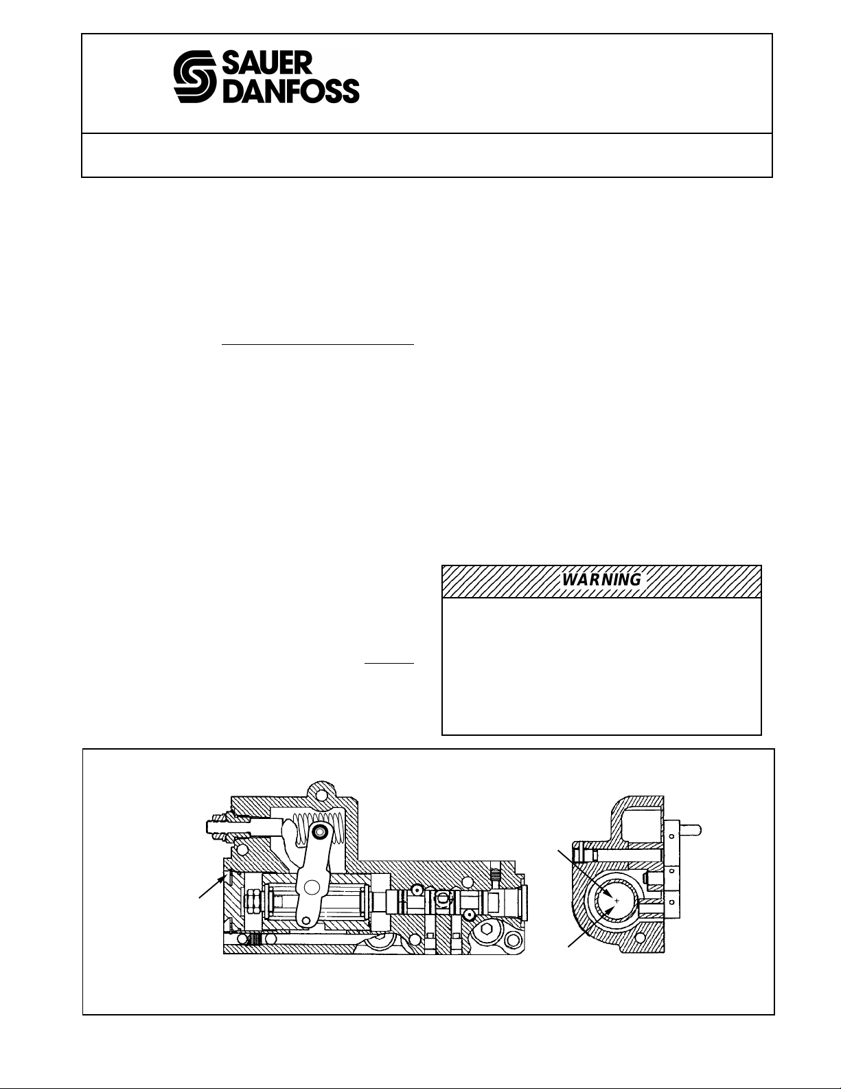
Service for the MCV115 HDC, Series 90 PV
This procedure covers the proper removal and installation of
those internal piece parts as outlined in the following steps.
(See Figures 1 and 2 for reference).
1. Remove the HDC from the pump, use a 5 mm socket hex
head and place it on a firm surface with the internal
workings facing up.
2. Locate the neutral adjust nut. Use an 11/16 hex wrench,
back out the neutral adjust assembly all the way and
remove from body.
Be careful not to disturb the locknut.
This will help ensure a positive pump neutral when
reinstalling this assembly.
3. Lift link/main adjust assembly away from housing. The
slider block may drop away from the link pin. Also, the
spring(s) in the housing should stay in place (30/55 cc,
one spring only; 75/180 cc, two springs).
4. Locate the large snap-ring. The cavity above the snapring should be cleaned of debris. Tap lightly with a
hammer on the plug below the snap-ring. This will relieve
the force when removing the snap-ring.
5. Using a snap-ring pliers, remove the snap-ring. Place a
blade screw driver under the lip of the plug and apply an
outward force at several points until plug is removed.
This will expose the Spool/Barrel Assembly (SBA). Now
place the HDC on end and grab hold of the two hex nuts
that are part of the SBA and pull out of housing.
6. Reassemble with the HDC on end. Gently lower the new
SBA into housing. If the SBA becomes stuck
GENTLY
tap into place.
7. Install new plug and snap-ring. All SBAs are shipped
with new plugs indicating the pressure range which is
stamped on the outside of the plug. Be sure that plugs
stay with their respective SBA, as this is the only means
of identifying the SBA pressure range.
8. Re-assemble the slider block onto the link pin as shown.
Place the link/main adjust assembly into the housing
while positioning the slider block flats into the barrel slot.
9. Install the neutral adjust assembly, making sure that the
spring(s) fall in place. While threading the neutral adjust
assembly into the housing, it will be necessary to assist
the main adjust by applying force in the direction as
shown. Keep applying this force while installing the main
adjust assembly until the O-ring contacts the housing.
Torque the main adjust nut to 30 ft·lb.
10. To ensure proper assembly, hold the feedback pin and
move side-to-side. It should move freely from stop to
stop, approximate.y 1/8 inch, before spring force is felt.
11. To install new control, align feedback pin to pump link.
Then carefully lower control onto pump.
12. Before installing mounting screws, check that control is
completely down on gasket. Install mounting screws
and tighten to 10 to 12 ft·lb.
2345678901234567890123456789012123456789012
2345678901234567890123456789012123456789012
2345678901234567890123456789012123456789012
2345678901234567890123456789012123456789012
WARNING
To adjust neutral requires operating the pump. Take
the necessary safety precautions. If the linkage is not
properly engaged maximum system pressure may occur
upon start up, and the machine may move. Ensure that
all personnel are not in a position to be injured should the
machine move. The EDC neutral position is critical to
ensure no machine movement upon start-up. Ensure
lock nut is tight (10 ft·lb).
HYDRAULIC DISPLACEMENT CONTROL (HDC)
SNAP RING
* Note: The pressure range is called out in the last two digits of the HDC P/N.
Figure 1.
RP-9601M
K20984
1
PRESSURE
RANGE
STAMPING
PLUG
Date: January 10, 1996
©Copyright 2000, Sauer-Danfoss (US) Company.
All rights reserved. Contents subject to change.
1923
Page 2
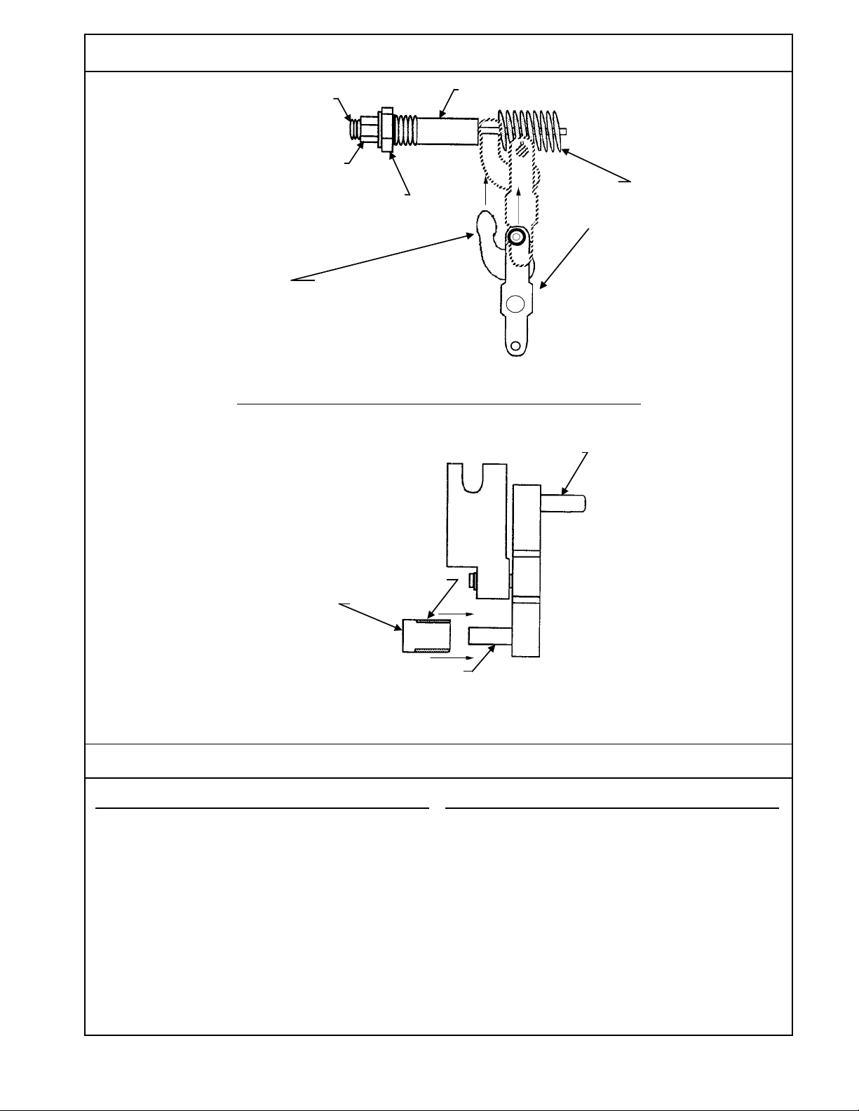
LINK/MAIN ADJUST ASSEMBLY
NEUTRAL ADJUST
SET SCREW
4 mm DIA.
LOCK NUT
13 mm DIA.
NEUTRAL ADJUST NUT 11/16
While installing the main adjust
assembly, apply force to this side
using a slotted screw driver.
NEUTRAL ADJUST ASSEMBLY
SPRINGS (2)
LINK/MAIN ADJUST
ASSEMBLY
FEEDBACK PIN
LINK/MAIN ADJUST
ASSEMBLY
RADIUS (4)
SLIDER BLOCK
FOR FURTHER ASSISTANCE CONTACT
NORTH AMERICA
Sauer-Danfoss (US) Company
Customer Service Department
3500 Annapolis Lane North
Minneapolis, Minnesota 55447
Phone: (763) 509-2084
Fax: (763) 559-0108
MAIN
ADJUST
LINK PIN
LINK
Figure 2.
EUROPE
Sauer-Danfoss GmbH & Company
Order Entry Department
Krokamp 35
Postfach 2460
D-24531 Neumünster
Germany
Phone: 49-4321-8710
Fax: 49-4321-871-184
1924
RP-9601M
K20984
2
Date: January 10, 1996
©Copyright 2000, Sauer-Danfoss (US) Company.
All rights reserved. Contents subject to change.
 Loading...