

Page 1
DESCRIPTION
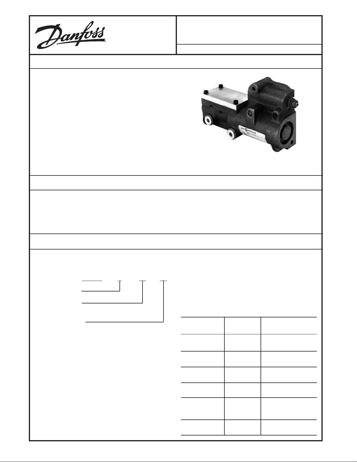
The MCV115 Series 90 Hydraulic Displacement Control
(HDC) is a hydromechanical pump stroke control which uses
mechanical feedback to establish closed loop control of the
swashplate angle of Danfoss Series 90 pumps.
The first stage, provided by the customer, produces a differential pressure to the HDC. The second stage uses the
differential pressure to drive its unique spool arrangement
and port oil to the pump servo cylinders. The second stage
spool configuration allows a null deadband (for machine
safety) in the pump's output while maintaining optimum
dynamic response to control commands.
FEATURES
MCV115
Hydraulic Displacement Control - PV
Series 90
BLN-95-9039-1 Issued: December 1992
• Servo control deadband independent of signal null
deadband; offers safety combined with accurate and
responsive control
ORDERING INFORMATION
The MCV115 HDC is ordered through the following part
number scheme:
MCV115 X XX XX
CONFIGURATION
PUMP CATEGORY
(frame/linkage size)
PRESSURE RANGE
CONFIGURATION
A Standard control
B Annular control (not available on 30, 42 or 55 cc
pumps)
PUMP CATEGORY
05 30, 42, 55 cc
07 75 cc
10 100 cc
13 130 cc (with short pin)
18 180 cc
• Fully tested to resist the off road environment
• Minimum long term null shift
PRESSURE RANGE
01 1.1 - 6.7 bar
02 1 - 11 bar
03 3 - 11 bar
04 8 - 16.5 bar
05 0.8 - 4.6 bar
06 5 - 15 bar
The pressure ranges available for the HDC are:
MCV115 PRESSURE
PART NUMBER RANGE COMMENTS
AXX01, BXX01 1.1 - 6.7 bar Same Pressure Range
(16 - 98 psi) as MCV112
AXX02, BXX02 1 - 11 bar Same Pressure Range
(15 - 160 psi) as MCV112
AXX03, BXX03 3 - 11 bar Same Pressure Range
(44 - 160 psi) as MCV112
AXX04, BXX04 8 - 16.5 bar Not available as
(116 - 239 psi) MCV112
AXX05, BXX05 0.8 - 4.6 bar Same Pressure Range
(11 - 66 psi) as MCV114's
lower range
AXX06, BXX06 5 - 15 bar Not available as
(73 - 218 psi) MCV112
© Danfoss, 2013-09 BLN-95-9039-1 1
.
.
Page 2
ORDERING INFORMATION
(continued)
HDCs ordered separate from the pump must have mounting kits ordered separately. The following table shows the pump/
kit relationships.
30/55 cc PUMP KIT (KIT NUMBER KK12655)
PART NUMBER QUANTITY DESCRIPTION
K11419 1 Gasket
9007314-0611 6 Screw
42 cc PUMP KIT (KIT NUMBER KK12642)
PART NUMBER QUANTITY DESCRIPTION
K11419 1 Gasket
9007314-0611 6 Screw
K09123 1 Seal Washer
TECHNICAL DATA
Some specifications apply to all HDCs. Others will vary
based on the MCV115 number scheme, as outlined in the
Ordering Information section.
THRESHOLD
See Pressure Range in the Ordering Information section. Defined as the center of hysteresis extracted to the
pump start stroke.
DEADBAND
Twice the threshold, ±7% of the rated pressure.
RATED PRESSURE
See Pressure Range, in the Ordering Information sec-
tion. Tolerance is ±10%. Defined as the pressure
required to reach rated pump output. Maximum pressure is 500 psid above rated pump case pressure. See
the Input Pressure Vs. Swashplate Angle Curve.
75/100/130 cc PUMP KIT (KIT NUMBER KK12675)
PART NUMBER QUANTITY DESCRIPTION
K11420 1 Gasket
9007314-0611 6 Screw
180 cc PUMP KIT (KIT NUMBER KK12618)
PART NUMBER QUANTITY DESCRIPTION
K11419 1 Gasket
9007314-0611 6 Screw
K09123 1 Seal Washer
TIME RESPONSE (Maximum)
1.0 seconds (0 to full stroke) (pressure limited valves)
2.0 seconds (full to full stroke) (pressure limited valves)
0.30 seconds (0 to full stroke) (non-pressure limited
valves)
0.40 seconds (full to full stroke) (non-pressure limited
valves)
SENSITIVITY
The valve will respond to a 2% change in input pressure
throughout the rated pressure range except for the
deadband region.
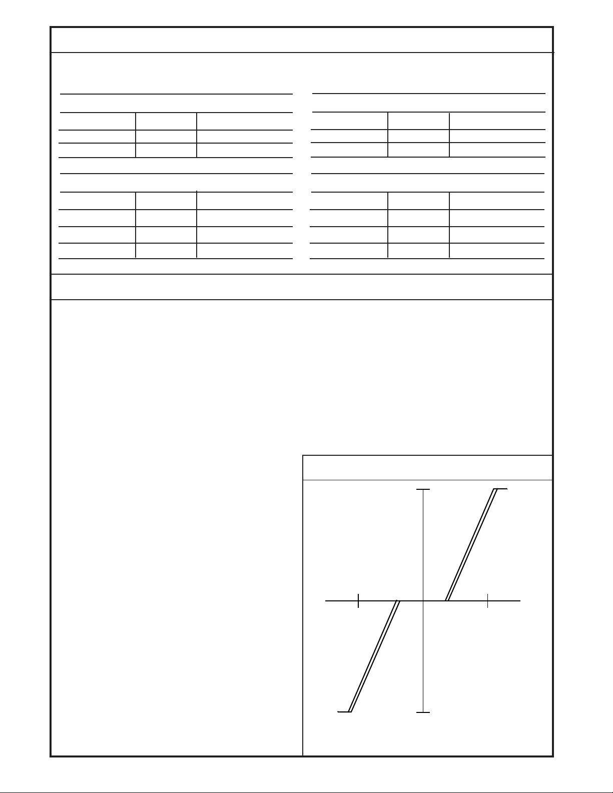
INPUT PRESSURE VS. SWASHPLATE ANGLE
17°
HYSTERESIS (Maximum)
7% of rated pressure. Measured on the hysteresis curve
generated at a frequency of 0.01 Hz with an excursion of
± rated pressure. The hysteresis measurement will be
made between 1 and 16 degrees of swash angle.
SYMMETRY
Input current required to reach rated output in each
direction must be equal within 15%.
LINEARITY
10% maximum of swashplate angle change between
any two points except within 1° of neutral.
RETURN TO NEUTRAL
The spool will return to neutral if the input differential
pressure signal is zero and mechanical feedback is
present.
OPERATING CHARGE PRESSURE
300 psi above case pressure (nominal).
BLN-95-9039-1
SWASHPLATE ANGLE
10
DELTA BAR
10
17°
Input Delta Pressure Vs. Swashplate Angle for the
MCV115 (Typical).
2
1637
Page 3

THEORY OF OPERATION
The HDC uses a unique spool-barrel-feedback arrangement
that serves to separate the null deadband from the feedback,
giving both safety against null drift and quick dynamic response to command changes. The barrel contains the spring
which provides the matching requirements for differential
pressure rating to output swashplate angle rating. The barrel
is driven directly by the feedback linkage from the swashplate.
See the Internal Workings Schematic.
The HDC's null adjust is set with a feedback spring to provide
an effective pressure-preload threshold, which is the amount
of differential pressure required to move the spool one
direction or the other. By tightening or loosening the main null
adjust screw, the fixed deadband is adjusted to the pump to
create the pump stroking start differential pressures.
As differential control pressure input from the external source
rises beyond the threshold, the spool moves in one direction
or the other, opening one of the control ports to charge
pressure, which ports oil to one of the pump servocylinders
to move the swashplate. As the swashplate moves, the drag
INTERNAL WORKINGS SCHEMATIC
linkage follows, moving the barrel in the opposite direction of
the spool input motion, driving the spool back to its neutral
position through the feedback spring within the barrel.
The HDC is a removable module from the main pump
housing such that no internal hardware changes are required
to the basic unit to switch from a manual to a hydraulic
displacement control. It will, however, be necessary to add
a charge check orifice, spring and retainer (which are part of
the pump assembly). The 90 Series HDC is comprised of
several physical sizes of controls to meet the requirements
of all the pump sizes. High response HDCs are not compatible with pressure limiters. This is a limit set by the design of
the pressure limiters within the pump.
Loose parts will be captive so there is no danger of them
falling into the pump during servicing. Control pressure ports
(from the external hydraulic input device) will be provided on
the boost stage as SAE-6 straight thread O-ring ports located
on the HDC's surface opposite the pump mounting surface.
MCV115
PUMP
HYDRAULIC CONTROL
VALVE
P
s
LINKAGE
P
t
P
t
AB
Schematic of the MCV115.
SWASHPLATE
1636
3
BLN-95-9039-1
Page 4

DIMENSIONS FOR 30, 42, AND 55 CC PUMPS
4,57 (0.180)
61,21 (2.410)
9/16-18 SAE STR. THD.
CONTROL PRESSURE INLET
60,45
(2.380)
7,11 DIA (6)
(0.280 DIA)
INSTALL SEAL WASHER HERE
ON 42 cc DEVICES
O-RING BOSS
2 PORTS
60,45
(2.380)
75,7
(2.98)
153,42 (6.040)
174,75 (6.880)
147,7 (5.814)
(0.236)
99,06 (3.90)
131,06 (5.160)
Dimensions in Millimeters (Inches).
6,0
72 (2.834)
44,7 (1.760)
30,99
(1.220)
13,97 (0.550)
11,94 (0.470)
NEUTRAL
ADJUST
41,66
(1.640)
81,28
(3.20)
6,35
(0.250)
94,49
(3.720)
1634
DIMENSIONS FOR 75 - 180 CC PUMPS
61,21
(2.410)
9/16-18 SAE STR. THD.
CONTROL PRESSURE INLET
70,61
(2.780)
7,11 DIA (6)
(0.280 DIA)
INSTALL SEAL WASHER
HERE ON 180 cc DEVICES
O-RING BOSS
2 PORTS
7 (0.275)
(2.63)
169,67 (6.680)
188,72 (7.430)
Dimension in Millimeters (Inches).
67
141,22 (5.560)
153 (6.023)
3,5
(0.137)
86,0 (3.385)
108,46 (4.270)
10,2 (0.40)
49,78 (1.960)
7,37 (0.290)
10,92
(0.430)
NEUTRAL
ADJUST
55,37
(2.180)
36,07
(1.420)
11,94 (0.470)
69,6
(2.740)
89,41
(3.520)
8,89
(0.350)
107,44
(4.230)
1635
BLN-95-9039-1
4
Page 5

ENVIRONMENTAL
3
3
3
3
3
3
3
3
3
3
3
3
3
3
3
TEMPERATURE
The valve will be functional and undamaged at oil
temperatures of –40° to 250° F (–40° to 121° C) with oil
viscosities from 40 to 6000 SUS. The valve will meet
performance specifications with oil temperatures of 70°
to 180° F (21° to 82° C).
SHOCK
50 g for 11 milliseconds. Three shocks in both directions
of the three mutually perpendicular axes for a total of 18
shocks.
VIBRATION
Withstands a vibration test designed for mobile equipment controls mounted on hydrostatic transmissions
consisting of two parts:
1. Cycling from 5 to 2000 Hz in each of the three axis.
TO INSTALL THE NEW CONTROL
2345678901234567890123456789012123456789012
2345678901234567890123456789012123456789012
2345678901234567890123456789012123456789012
2345678901234567890123456789012123456789012
2345678901234567890123456789012123456789012
Exercise care when placing the valve on a surface before
mounting on a transmission. Dropping or otherwise forcefully setting the valve down may damage the pin.
WARNING
2. Resonance dwell for one million cycles for each
resonance point in each of the three axis.
Run from 1 g to 46 gs. Acceleration levels vary with
frequency.
FILTRATION
The system hydraulics shall have 10 micron or better
filtration. The pump will contain screen filters near the
interface to the HDC at the charge port and control ports.
FLUID
Automatic transmission fluid or hydraulic oil (Ref: Mobile DTE 24 or equivalent).
DIMENSIONS
See the Dimension drawings.
1. Place a new gasket on the pump housing. Ensure that
the control orifice and spring are in the proper position
in the control.
2. Engage the pin on the control into the mating hole in the
link attached to the swashplate. See the Linkage
Assembly and Port Locations photo.
2345678901234567890123456789012123456789012
2345678901234567890123456789012123456789012
2345678901234567890123456789012123456789012
2345678901234567890123456789012123456789012
2345678901234567890123456789012123456789012
WARNING
Do not put the MCV115X13XX HDC on an older model
pump. Consult factory for proper installation. Older style
pumps previously used MCV112 HDCs with a manifold
between the HDC and the 130 cc pump. Directlymounted MCV115s use a pin that is too short for older
pumps. Using them improperly will result in pump displacement without feedback signal to the HDC.
2345678901234567890123456789012123456789012
2345678901234567890123456789012123456789012
2345678901234567890123456789012123456789012
2345678901234567890123456789012123456789012
2345678901234567890123456789012123456789012
WARNING
Uncontrollable vehicle or load movement will occur upon
start-up if the control is installed without proper engagement of the control feedback link pin into the swashplate
link.
During control installation, feel for pin engagement by
tipping the control before installing the mounting screws.
The control will not tip more than 5° if the pin is engaged.
3. Ensure that the pin is engaged in the link by tilting the
control upwards from the narrower end. If the pin
catches in the link and allows only a slight upward tilt,
there is positive engagement. If the control swings up
freely, the pin is not properly aligned.
4. Position the control into place against the pump housing. Align the gasket. Install the cap screws (On 42 cc
and 180 cc pumps use the included seal washer per the
Dimension drawings.) and torque to 10-12 ft-lbs.
LINKAGE ASSY & PORT LOCATIONS
CASE DRAIN PORT
SYSTEM
PRESSURE
"B" GAUGE
PORT
CHARGE
PRESSURE
GAUGE PORT
Vehicle or load movement can also result from lack of or
improperly adjusted control neutral. Follow service
manual procedures for adjusting neutral after start-up.
Always raise the vehicle, or block the vehicle load, from
moving upon start-up.
SYSTEM
PRESSURE
"A" GAUGE PORT
Assembly of control linkage and location of pump ports
for the MCV115.
BLN-95-9039-1
5
1646
Page 6

PUMP NEUTRAL ADJUSTMENT
3
3
3
3
3
Use the following procedure to bring the pump to neutral once
the hydraulic displacement control has been mounted.
1. Install a 500 psi gauge into the charge pressure gauge
port on the pump. See the Linkage Assembly and Port
Locations photo.
2. Loosen the null adjust plug on the null adjust screw.
3. Start the prime mover and run at low idle.
2345678901234567890123456789012123456789012
2345678901234567890123456789012123456789012
2345678901234567890123456789012123456789012
2345678901234567890123456789012123456789012
2345678901234567890123456789012123456789012
WARNING
To adjust neutral requires operating the pump. Take the
necessary safety precautions, such as having unnecessary personnel stand away from the machine. Maximum
system pressure may occur upon start up, and the
machine may move. Ensure that the operator is not in a
position to be injured should the machine move.
4. Warm the system up for several minutes to bleed air.
5. Slowly increase the prime mover speed to rated rpm.
(Ensure that the input differential pressure is zero.)
6. If the transmission operates as shown by motor shaft
rotation, reduce speed to idle. Using a 4 mm internal hex
wrench, slowly turn the null adjustment screw clockwise
or counterclockwise until the transmission does not
operate. Repeat step 5. Note that charge pressure
should drop with forward or reverse stroking of the pump
swashplate due to the shifting of the shuttle valve in the
motor manifold. Slowly turn the null adjust screw
clockwise until charge pressure decreases.
7. With the hex wrench, slowly turn the null adjustment
screw counterclockwise, observing the wrench angle
rotation, until charge pressure decreases again (charge
pressure will rise in neutral and drop when going into
stroke).
8. Turn the adjustment screw clockwise half the amount of
the turn observed in step 7. This should be the center
of neutral.
9. Hold the adjustment screw and securely tighten the null
adjust plug to 3–5 ft-lbs. Note that if a motor is used that
does not have a manifold, neutral should be adjusted
(steps 7–9) by observing the motor shaft rotation without
a load.
10. Stop the prime mover.
11. Run the system briefly to ensure that it operates proportionally on both sides of null. Swashplate movement
can be verified by watching motor shaft rotation without
a load.
CUSTOMER SERVICE
NORTH AMERICA
ORDER FACTORY INSTALLED MCV115s ON PUMPS
FROM
Danfoss (US) Company
2800 East 13th Street
Ames, Iowa 50010
Phone: (515) 239-6000
Fax: (515) 239-6318
ORDER INDIVIDUAL MCV115s FROM
Danfoss (US) Company
Customer Service Department
3500 Annapolis Lane North
Minneapolis, Minnesota 55447
Phone: (763) 509-2084
Fax: (763) 559-0108
DEVICE REPAIR
For devices in need of repair, include a description of the
problem, a copy of the purchase order and your name,
address and telephone number.
RETURN TO
Danfoss (US) Company
Return Goods Department
3500 Annapolis Lane North
Minneapolis, Minnesota 55447
EUROPE
ORDER FROM
Danfoss (Neumünster) GmbH & Co.
Order Entry Department
Krokamp 35
Postfach 2460
D-24531 Neumünster
Germany
Phone: 49-4321-8710
Fax: 49-4321-871355
BLN-95-9039-1
6
 Loading...