

Page 1
DESCRIPTION
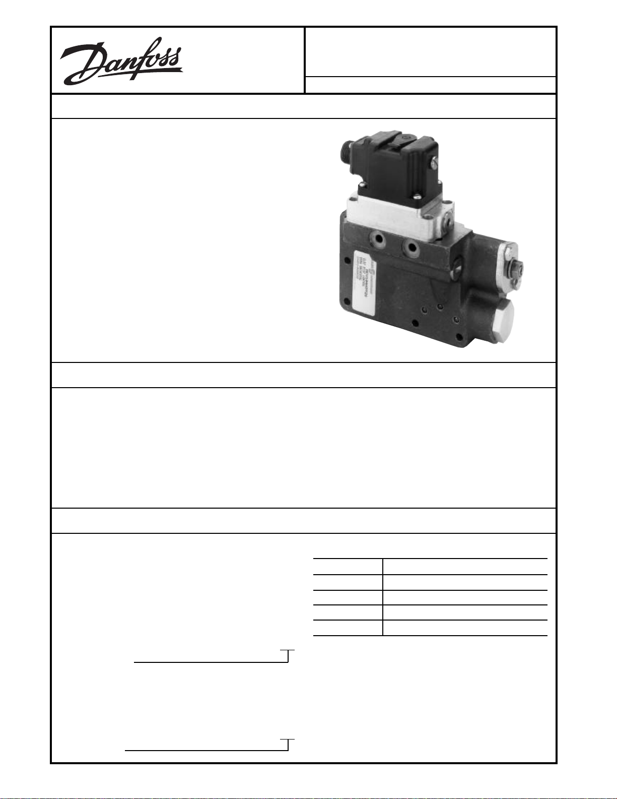
The MCV109A Electrical Displacement Control (EDC-MV) is
a two-stage electrohydraulic motor stroke control which uses
mechanical feedback to establish closed loop control of the
swashplate angle of Danfoss Series 2X and Series
3X motors.
The first stage, the MCV116 Pressure Control Pilot, is a
torque motor actuated, double nozzle flapper valve that
produces a differential output pressure proportional to the
applied electrical signal. The second stage uses the differential pressure to drive its double spool arrangement and port
oil to the motor servo cylinders.
MCV109A
Electrical Displacement Control-MV
BLN-95-8985-1 Issued: June 1995
FEATURES
• Single command source can be used to control both
hydrostatic pump and motor
• Servo control deadband independent of signal null
deadband: offers safety combined with accurate and
responsive control.
• Resistance to the environment: standard silicone oil filled
torque motor, environmentally sealed first/second stage
interface, full environmental testing.
• Pilot supply screens in series, upstream screen is externally serviceable
• First and second stages can be individually replaced
• Swashplate movement can be visually detected
• Single or dual coil torque motor
ORDERING INFORMATION
MCV109s are ordered for the particular motor on which they
are to be mounted. Link Installation Kits, as ordered in the
table below, include: orifices, retaining ring, drag link, spacer
plate, swashplate pin, link and ball assembly, hex screws, Orings and gaskets. In some cases not all the above are
necessary for installation and they are not included in the kit.
TABLE A. INFORMATION NECESSARY TO SPECIFY
THE LINK INSTALLATION KIT.
KK041 XX
MOTOR SERIES
Order the valve itself through the following table:
TABLE B. INFORMATION NECESSARY TO SPECIFY
THE ELECTRICAL DISPLACMENT CONTROL.
MCV109A59 XX
PILOT STYLE
© Danfoss, 2013-09 BLN-95-8985-1 1
The EDC Pilot comes in five styles:
PILOT STYLE DESCRIPTION
22 Single Coil, Packard Connector
23 Dual Coil, Packard Connector
26 Single Coil, MS Connector
27 Dual Coil, MS Connector
The standard EDC Pilot is a single coil (one input to the
torque motor) (see Block Diagram), silicone oil filled, Packard
Connector device. The options are a dual coil, which allows
two command sources to be combined at the torque motor,
the resulting signal being the difference between the two, a
MS3102C14S-2P (Danfoss Part Number K01314)
connector.
.
.
Page 2
ORDERING INFORMATION
1234567890
1234567890
1234567890
ITEM PART ITEM PART
NUMBER NUMBER DESCRIPTION NUMBER NUMBER DESCRIPTION
1 K03383 Mating Connector 2-Pin (Unassembled) 14 K07028 Plug
K03384 Mating Connector 4-Pin (Unassembled) K07011 O-Ring For Item 14
2 K03377 Device Connector 2-Pin (Unassembled) 15 K07163 Spacer - Size 20
K03378 Device Connector 4-Pin (Unassembled) 16 K07164 Spacer - Size 26
3 K01314 Device MS Connector 17 K07128 (3) Port Screens
4 K08106 Mating MS Connector (90°) 18 K07136 (2) .052 Orifices
5 K07055 #10-32 X 5/8 Socket Head Cap Screw 19 K07006 (3) O-Ring For Ports
6 K01291 (2) Plugs 20 K07182 EDC Gasket
7 K07612 Filter Assembly 21 K07160 Linkage Bushing
8 K07034 (2) Screws, Null Adjust Cover K07009 O-Ring, Linkage Bushing (1 Each)
9 K08387 Seal Washer 22 K02611 Snap Ring
10 K10911 Seal Washer Retainer 23 K04448 Plug
11 K07000 #3/8-32 Nut Null Adjust 24 K07159 Plug
12 K08133 Gasket Null Adjust Cover K07010 O-Ring For Item 15
13 K07158 Null Adjust Cover 25 K07005 O-Ring Linkage Shaft
26 CAUTION
Do Not Remove (4) Cover Screws
1238E
BLN-95-8985-1
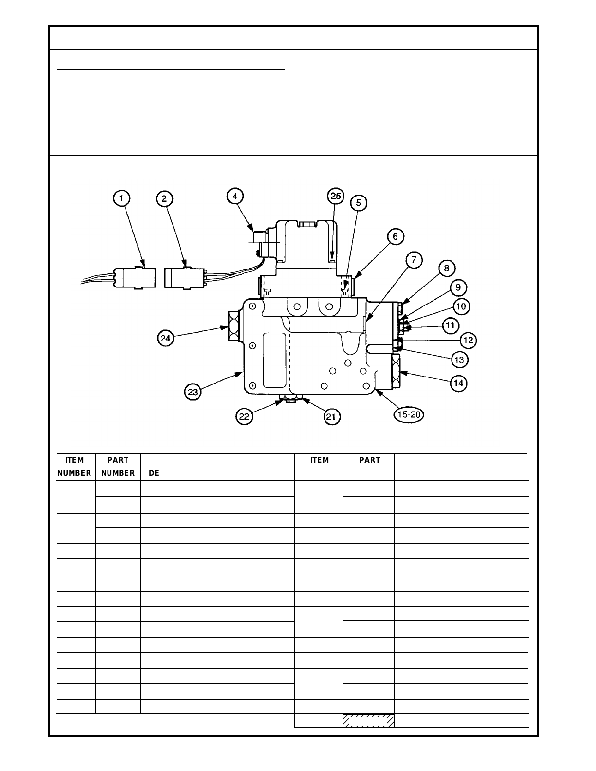
SPARE PARTS
(continued)
See the Spare Parts diagram for a list of spare parts available
for the MCV109A. Other non-standard spare parts, such as
orifices, may be available upon request.
Order Danfoss Pressure Override Valve through
'DQIRVV'LVWULEXWRUV
.
SPARE PARTS
Order the EDC either factory installed on motors or as an
individual control.
2
Page 3
TECHNICAL DATA
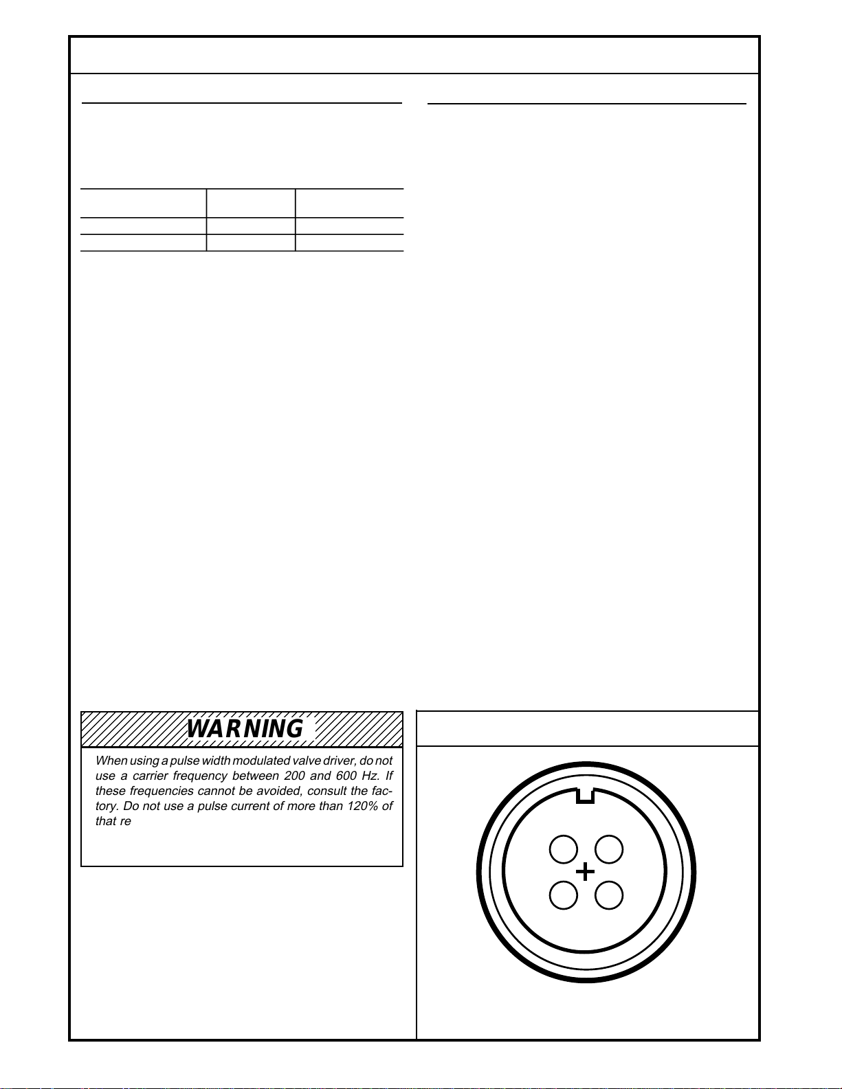
WARNING
When using a pulse width modulated valve driver, do not
use a carrier frequency between 200 and 600 Hz. If
these frequencies cannot be avoided, consult the factory. Do not use a pulse current of more than 120% of
that required for full output. Failure to meet the above
conditions can cause severe damage to the valve which
will result in improper system operation.
CONNECTION DIAGRAM
Pin Orientation of the Optional MS Connector, Part
Number (K01314) MS3102C14S-2P.
See Performance Curve and Wiring Schemes diagrams.
The device is capable of operating continuously at 125%
of rated current at 104° C (220° F) oil temperatures.
COIL IMPEDANCE
23 ohms (single coil)
19 ohms (A, B terminals) and
15.5 ohms (C, D terminals) (dual coil)
HYSTERESIS
4 mA (.85 degrees swashplate angle) maximum at .01
Hz
LINEARITY
10% maximum of swashplate change between any two
points
PHASING
A positive voltage applied to Terminal B (Red lead) will
cause a pressure rise at the C2 port
SENSITIVITY
The valve shall respond to a 2% change in input current
throughout the rated current range
1276
D
C
A
B
ELECTRICAL
THRESHOLD/RATED OUTPUT CURRENT
The current required to come off stroke (threshold) and
to reach full 6° destroke (rated output) will be per the
following table.
FINAL TWO DIGITS THRESHOLD RATED OUTPUT
OF EDC PART # SETTING CURRENT
22 or 26 85 mA 140 mA (±10%)
23 or 27 125 mA 185 mA (±10%)
HYDRAULIC
FLUID
Automatic transmission fluid or hydraulic oil, such as
Mobil DTE 24 or equivalent
FILTRATION
The system hydraulics shall have 10 micron or better
filtration
CASE PROOF PRESSURE
500 psi at 121° C (250° F)
CASE PRESSURE WITH NO EXTERNAL LEAKAGE
200 psi, minimum
RATED CASE OPERATING PRESSURE
40 psi
RATED FLOW
1.15 minimum to 1.45 maximum gpm (standard device)
1.50 minimum gpm (high response)
with cylinder ports connected and 200 psi supply pressure
HYSTERESIS
4 mA maximum at .01 Hz
OPERATING SUPPLY PRESSURE
215 psi above case pressure
MAXIMUM NULL LEAKAGE
.65 gpm (standard)
1.25 gpm (high response)
at 200 psi across the valve with oil of 145-160 SUS at
38° C (100° F)
3
BLN-95-8985-1
Page 4
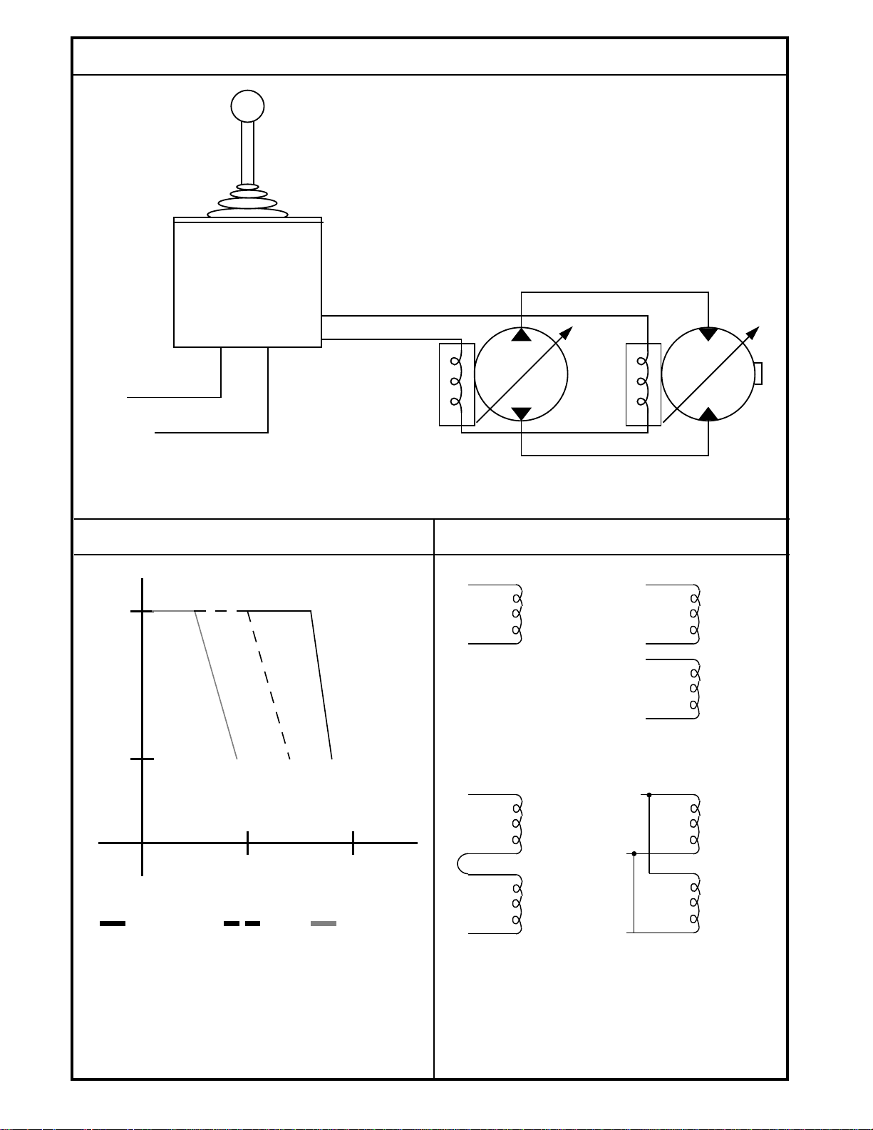
WIRING DIAGRAM (Typical)
+A
B
+A
B
+C
D
+A
B
C
D
+A
B
C
D
Single coil 140 mA
with 3.3 Vdc input
at full destroke.
Using one of the two dual coils,
185 mA with 2.8 Vdc (C, D) or
3.6 Vdc (A, B) input at full destroke.
Dual coils in series,
72 mA with 4.4 Vdc
input at full destroke.
Dual coils in parallel,
185 mA with 1.4 Vdc
input at full destroke.
-V
GROUND
MCH CONTROL HANDLE
MCV104
EDC
PV MV
MCV109
EDC
A
B A
B
SWASHPLATE ANGLE (DEGREES)
OUTPUT CURRENT (mA)
18
6
100 200
03, 04, 07, 08 11 01, 02, 05, 06
PERFORMANCE CURVE
1444
WIRING SCHEMES
Current vs. Swashplate Angle for the MCV109. Legend
References the Last Two Digits of the Part Number.
BLN-95-8985-1
1446A
Wiring Schemes Using Four Different Pilot Valve Configurations for the EDC. Input Voltages Specified at
24° C.
4
1447
Page 5

DIMENSIONS
FOLLOWING
CONFIGURATIONS
ONLY AS SHOWN
3XXX
4XXX
7XXX
8XXX
EXCEPT 33, 34
& 36
SERIES
PUMPS
24,89
(.98)
REF
3/8 O.D. TUBE FITTING O-RING
PORT PER SAE - J514 - 9/16-18 UNF
2 PLACES. (PLUGS INSTALLED)
NULL
ADJUST
SCREW
47,50
(1.87)
MAX
71,12
(2.8) MAX
190,5
(7.5) MAX
193,0
(7.6) MAX
Dimensions of the MCV109A in Millimeters (Inches).
THEORY OF OPERATION
A command source such as a joy stick, control handle, or
electronic controller applies a dc current signal to the pilot
stage of the MCV109A. The input current commands the
pilot's torque motor stage, a bridge network consisting of an
armature mounted on a torsion pivot and suspended in the
air gap of a magnetic field. Two permanent magnets polarized in parallel and a connecting plate form a frame for the
magnetic bridge. At null the armature is centered in the air
gap between the magnets' opposing poles by the equivalence of their magnetic forces and the null adjust centering
springs. As input current rises, the end of the armature
becomes biased either north or south, depending on the
direction of the current. The resulting armature movement is
determined by the amperage of control current, the spring
constant and the differential pressure feedback forces explained below. See Internal Workings Schematic.
The magnetic bridge output, flapper torque, in turn controls
the hydraulic bridge ratio. At null, the flapper is centered
between two nozzles. Upstream from each nozzle is an
orifice which provides a nominal pressure drop when the
system is at null. Between the nozzle and the orifice on each
side is a control port. As the torque motor shifts the flapper
away from one nozzle toward the other, a differential control
pressure results, the high side being the one nearer the
flapper. Fluid pressure rises on this side and moves the
flapper back towards null. When the torque output from the
motor equals the torque output from the pressure feedback,
the pilot system is in equilibrium. It is this pressure feedback
that makes the pilot a stand-alone, closed loop, pressure
control valve.
The second stage's null adjust is set with the modulating
spring compressed to the equivalent of 95 psi, which is the
amount of differential pressure required to move the actuator
spool. This is a factory setting that determines the threshold
point at which the motor will begin to destroke. By tightening
or loosening the null adjust screw, the motor can be accurately phased with a pump.
As differential control pressure (C2-C1) rises beyond the 95
psi threshold, the actuator spool moves, pivoting the crosslink about its center. The pivoting cross-link pushes the
porting spool in the opposite direction of the actuator spool.
When the porting spool has moved far enough, oil is ported
to the motor servo cylinder, moving the swashplate. As the
swashplate moves, the drag linkage follows, pivoting the
cross-link about the stationary end of the actuator spool,
driving the porting spool back to its neutral position. Because
the feedback signal is entered into the control loop after the
command has been input, response time and accuracy are
enhanced.
5
BLN-95-8985-1
1445A
Page 6

INTERNAL WORKINGS SCHEMATIC
Schematic of the Internal Workings of the MCV109A. Oil Paths Shown Externally for Clarity.
1303
ENVIRONMENTAL
TEMPERATURE
The valve shall be functional and undamaged at oil
temperatures of -40° to 121° C (-40° to 250° F). The
valve shall meet performance specifications at oil tem-
peratures of 21° to 82° C (70° to 180° F).
SHOCK
50 gs for 11 milliseconds. Three shocks in both directions of the three mutually perpendicular axes for a total
of 18 shocks.
VIBRATION
Withstands a vibration test designed for mobile equipment controls consisting of two parts:
1. Cycling from 5 to 2000 Hz in each of the three axes.
2. Resonance dwell for one million cycles for each
resonance point in each of the three axes.
Subject to acceleration levels of 1g to 46 gs. Acceleration level varies with frequency.
HUMIDITY
After being placed in a controlled atmosphere of 95%
humidity at 49° C (120° F) for 10 days, the EDC will
perform within specification limits.
DIMENSIONS
See Dimension drawing.
WIRING
Two wiring styles are available: MS and Packard connectors.
The MS connector is Part Number K01314 (MS3102C14S2P) and has four pins, only two of which are used (A and B)
for single coil devices. See Wiring Schemes diagram for
proper wire phasing and Connection diagram for pin locations. For both MS and Packard connectors, phasing is such
that a positive voltage on the Red wire (Pin B) will cause a
pressure rise at the C2 port for single coil valves.
Included in the mating Packard connector bag assembly
(which must be ordered separately) are:
1. 2 (or 4) 14 - 16 gauge sleeves
2. 2 (or 4) 18 - 20 gauge sleeves
3. 1 plastic housing
4. 2 (or 4) green cable seals (accept 2,2-2,8 mm wire
diameter)
5. 2 (or 4) gray cable seals (accept 2,81-3,49 mm wire
diameter)
6. 2 (or 4) blue cable seals (accept 3, 50-4, 21 mm wire
diameter)
See Ordering Information.
BLN-95-8985-1
6
Page 7

WIRING
DIMENSION A
DIMENSION A, PACKARD CONNECTOR
1123
Dimension A For Selecting Correct Terminal.
DISTANCE, PACKARD CONNECTOR
CRI MP
19. 5 mm MAX.
CABLE
SEALS
SIDE "B"
RED
BLACK
SHROUD
CONNECTOR
SIDE "A"
DOUBLE-PLUG SEAL
TOWER CONNECTOR
BLN-95-8985-1
(continued)
To assemble the female tower connector, use the following directions:
1. Isolate the wires that extend from the command source
to the EDC.
2. Strip back the insulation 5.5 millimeters on both wires.
3. Push a ribbed cable seal over each of the wires with the
smaller-diameter shoulder of the seals toward the wire
tip. Select the pair of seals that fits tightly over the wires.
The distance from the tip of the wires to the first (nearest)
rib should be 9.5 millimeters. Thus the installation should
just protrude beyond the seal.
4. Select the larger of the two sets of pins, as measured at
Dimension A (see Dimension A diagram), if using a 1416 gauge wire. Choose the smaller if using 18-20 gauge.
Place the wire into the socket so that the seal edge is
pushed through and extends slightly beyond the circular
tabs that hold it in place. Crimp in the locations shown
(see Distance, Packard Connector diagram) with a
Packard 12014254 crimp tool available from your local
Packard distributor.
5. The distance from the back of the tangs to the furthest
rib may not exceed 19.5 millimeters. See Distance,
Packard Connector diagram.
6. Manually insert the assembled wires into the back end
(large hole) of the plastic housing. Push until the wire
detents with an audible click, then pull back slightly to
ensure proper seating. (Observe the proper phasing of
the wires when installing: black wire to "A" hole, red to
"B", black to "C" and red to "D".) Terminals may be
removed from the connector bodies with a Packard
12014012 removal tool.
7. Swing the holder down into the detented position to trap
the wires in the housing. The third rib should be sealed
into the housing.
8. Plug the shroud connector from the valve into the tower
connector just constructed. They are sealed with a
double (or quadruple) plug seal over the double (or
quadruple) barrel of the tower assembly. The two connector halves should detent into each other. See Connector Parts Identified diagram.
Distance From Tang to Third Rib of
Packard Connector.
1077A
CONNECTOR PARTS IDENTIFIED,
PACKARD CONNECTOR
1078A
Interlocked Connector Halves With Parts Identified.
Two Wire Connection Shown.
7
Page 8

INSTALLATION
A highly reliable connection between the swashplate and the
drag link is necessary for safe operation. An unreliable
connection may result in loss of feedback with a resulting loss
of control. Series 3X motors meet this requirement, but all
Series 2X units not already equipped with an EDC or Hydraulic Displacement Control (HDC) must be retrofitted with the
appropriate drag link, press fit pin and retaining ring, replacing the slip fit headless pin and E-rings used to attach the
original drag link. Series 20 and 26 models require a spacer
plate between the control and the motor housing.
Series 3X motors with Serial Number of 82-34-00000 or
greater will accept the EDC without modification of the motor.
These units have a clearance notch cast into the swashplate
that provides additional room for link movement. Series 3X
motors with Serial Numbers of less than 82-33-99999 may
not be fitted with the EDC without modification of the
swashplate by 'DQIRVV.
Prior to mounting any control on a motor, ensure that both the
control and the control feedback link are correct for the motor
as evidenced by the series number stamped on the link and
the part number labeled on the control body. See Table C
and Warning.
TABLE C. THE FOLLOWING TABLE CORRELATES THE
MOTOR SERIES NUMBER WITH THE SERIES NUMBER
STAMPED ON THE SIDE OF THE CONTROL FEEDBACK
LINK PROTRUDING FROM THE CONTROL.
SERIES LINK MARKING
20, 20 (1/4 spacer)
21, 22 21, 22
23 23
24 24
25 25
26 26 (1 1/2 spacer)
27 27
33, 34, 36 33, 34, 36
1234567890123456789012345678901212345678901
1234567890123456789012345678901212345678901
1234567890123456789012345678901212345678901
1234567890123456789012345678901212345678901
1234567890123456789012345678901212345678901
1234567890123456789012345678901212345678901
WARNING
Exercise care when placing the valve on a surface before
mounting on a transmission. Dropping or otherwise
forcefully setting the valve with the linkage down may
break the crosslink, resulting in a lack of response to
command.
MOUNTING
Follow the procedure outlined below to attach the EDC to the
motor.
REMOVING THE OLD HARDWARE
1. Thoroughly clean all external surfaces of the motor and
control with steam or solvent. Blow dry.
2. Remove the existing control from the motor by removing
the nine hex head screws from the housing. Slip the pin
on the control linkage out of the end of the swashplate
drag link. See Swashplate Drag Link diagram.
3. Remove the case drain fitting from the side of the motor
on which the control was mounted.
4. Remove the E-ring from the inside end of the connecting
pin. Use caution not to drop the E-ring into the housing
during the removal. See Pin Connection diagram.
5. Remove the pin from the swashplate drag link and
swashplate through the case drain port using a magnet
or other tool. Remove the drag link. On some models
it may be necessary to hold the swashplate off neutral to
align it with the case drain hole. See Swashplate
Assembly diagram.
SWASHPLATE DRAG LINK
1124B
Swashplate Drag Link/Control Feedback Link
Connection Between Original Control and Motor.
BLN-95-8985-1
8
Page 9

PIN CONNECTION SWASHPLATE ASSEMBLY
The control and feedback link must have the proper
identification in order to be installed. Installing a control
with an improper control feedback link can result in a
control failure which can cause the motor swashplate to
move to full angle and remain there independent of
signal input.
Do not attempt to install an EDC on a motor for which it
was not originally designed without changing the linkand-ball assembly. Merely changing the swashplate
drag link is inadequate. See Ordering Information for the
necessary link-and-ball assembly number. In no case
should a valve originally built for a Series 2X motor be
used on a Series 3X motor.
WARNING
C. Lubricate the shaft O-ring and replace the bushing
over the shaft. Torque to the body (10 - 15 foot
pounds) so that the feedback shaft extends through
the bushing.
D. Install the retaining ring in the groove on the shaft.
2. Align one end of the replacement swashplate drag link
with the holes in the swashplate link arms.
3. Insert the press fit pin through the case drain port to trap
the drag link in the swashplate clevis. It will be necessary
to tap the pin into place until the head of the pin is flush
to the clevis.
4. Install the retaining ring by forcing it onto the tapered end
of the pin until it locks into the groove on the pin shaft.
Again, use caution not to drop any components into the
motor housing.
5. Install the supplied spacer between the control and the
motor housing. If the motor is a 20 Series, the spacer is
one-quarter inch thick; if it is a 26 Series, the spacer is
1 1/2 inch thick. Other series’ do not require a spacer.
One gasket and 3 O-rings must be installed on the under
side of the spacer.
6. Install one .052-inch diameter orifice in each servo
passage if normal swashplate response is desired. Two
orifices are used instead of the single orifice used in the
charge supply passage of manual controls. Install 3 Orings and a gasket. If a spacer is used, there should now
be 6 O-rings and 2 gaskets in place.
7. Engage the pin on the control in the drag link and swing
the control into place against the motor housing. The
drag link should be on the cylinder block side of the
swashplate. Install the seven mounting screws and
tighten to 10-11 foot pounds of torque.
1125C
DRAG LINK
REMOVE "E" RINGS,
PIN AMD DRAG LINK
Location of Swashplate Assembly in Motor Housing. Pin Connection to Swashplate.
Shown Disassembled for Clarity.
MOUNTING
MOUNTING THE NEW HARDWARE
(continued)
1. Recheck the series number on the control feedback link
to ensure that it is compatible with the motor. Follow the
procedure outlined below to install the linkage. See
Parts Location Drawing.
A. Unscrew the bushing, using care not to damage its
O-ring. See Swashplate Assembly diagram.
B. Install the new linkage assembly shaft through the
swashplate feedback shaft hole. Place the ball in
the crosslink ball cavity.
1126B
BLN-95-8985-1
9
Page 10

PARTS LOCATION DRAWING
Each MCV109 is factory calibrated so that the motor will
begin to destroke from 18° at the specified threshold input
current (see Technical Data section) to 6° which is full
destroke. This setting should not require adjustment.
If for some reason adjustment of neutral is necessary, a turn
of the null adjustment screw will vary the current/swashplate
angle curve (see Performance Curve diagram) vertically. A
clockwise turn will reduce the angle at which the swashplate
begins to destroke from 18° to a smaller angle. Physical
stops prevent the motor from destroking below 6°. A counterclockwise turn increases the fully-destroked angle above 6°.
Physical stops prevent the swashplate from exceeding 18°.
MOTOR THRESHOLD ADJUSTMENT
Use the following procedure to bring the hydraulic motor to a
threshold setting. The procedure describes "stages" of the
transmission, so that the motor starts to destroke just as the
pump reaches full stroke. This ensures a smooth, continuous
rise in motor shaft speed as command increases.
If a tachometer is unavailable, or if for some other reason the
following procedure is impractical, similar results can be
obtained by running the machine at different MCV109A
threshold adjustments. There should be no "dead spots" in
which increased command gives no increased speed. Nor
should there be spots in which increased command gives a
faster rise in speed than at high and low command extremes.
1. Disconnect the wires connecting the EDC pilot of the
MCV109 EDC-MV on the motor.
2. Install a mechanical or photoelectric tachometer on the
output shaft of the hydraulic motor.
3. Run the EDC electrical (or HDC-PV hydraulic) command source to maximum.
4. Slowly reduce the command source until the motor shaft
starts to decrease speed as shown by the tachometer.
This point represents full pump output. Note the RPM
indication level on the tachometer. Note the command
source position and the engine speed.
5. Reconnect the wires to the EDC-MV. Re-start the hydrostatic transmission. Using a 9/16-inch wrench, loosen
the hex lock nut on the null adjustment screw.
6. Using a 3/16 inch internal hex wrench, slowly turn the
null adjustment screw counterclockwise until the tachometer indicates the full pump output from Step 4.
(Note: Clockwise null adjust rotation increases shaft
output speed.) Then turn the screw clockwise until shaft
speed just starts to increase.
7. Hold the adjustment screw and securely tighten the hex
lock nut on the adjustment screw to 14-18 foot-pounds.
8. Run the system briefly to ensure that it operates proportionally. Swashplate movement can be verified by watching movement of the swashplate feedback shaft, shown
in Parts Location Drawing.
WARNING
To adjust neutral requires operating the pump. Take the
necessary safety precautions such as having unnecessary personnel stand away from the machine. Maximum
system pressure may occur upon start up, and the
machine may move. Ensure that the operator is not in
a position to be injured should the machine move.
LINKAGE
ASSEMBLY
CROSSLINK
BALL
CAVITY
BUSHING
RETAINING
OPTIONAL ORIFICES (2)
SWASHPLATE FEEDBACK
SHAFT HOLE
RING
Location of Parts When Installing a New Link and Ball Assembly. Separate
Assembly Parts Shown for Information Only; Do Not Attempt to Disassemble.
MOTOR NEUTRAL ADJUSTMENT
1858
1237B
10
Page 11

CUSTOMER SERVICE
NORTH AMERICA
ORDER FROM
Danfoss (US) Company
Customer Service Department
3500 Annapolis Lane North
Minneapolis, Minnesota 55447
Telephone: (763) 509-2084
Fax: (763) 559-0108
DEVICE REPAIR
For devices in need of repair, include a description of the
problem, a copy of the purchase order and your name,
address and telephone number.
RETURN TO
Danfoss (US) Company
Return Goods Department
3500 Annapolis Lane North
Minneapolis, Minnesota 55447
EUROPE
ORDER FROM
Danfoss (Neumünster) GmbH & Co.
Customer Service Department
Krokamp 35
Postfach 2460
D-24531 Neumünster
Germany
Telephone: 49-4321-8710
Fax: 49-4321-871-284
11
BLN-95-8985-1
 Loading...