

Page 1
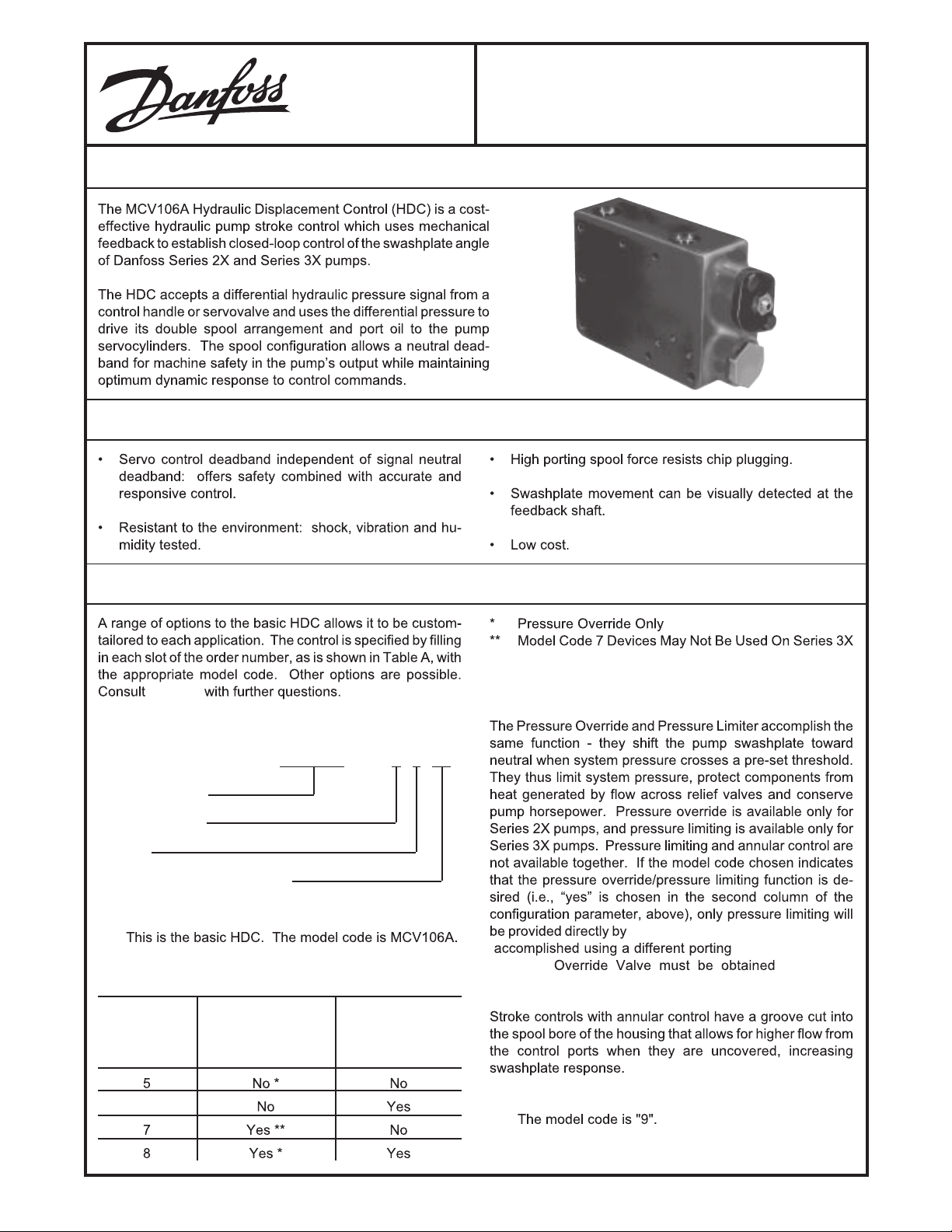
DESCRIPTION
FEATURES
MCV106A
Hydraulic Displacement Control
ORDERING INFORMATION
Danfoss
TABLE A. INFORMATION NECESSARY TO SPECIFY
THE HDC.
MCV106A X 9 XX
DEVICE IDENTITY
CONFIGURATION
MODEL
MODULATING PRESSURE RANGE
1. DEVICE IDENTITY
2. CONFIGURATION
MODEL PRESSURE ANNULAR
CODE LIMITER OR CONTROL
PRESSURE
OVERRIDE
Pumps
Pressure
Danfoss .
Danfoss (pressure limiting is
spool); the
through
6
© Danfoss, 2014-05 11152454 • Rev AA • May 2014 1
3. MODEL
Page 2
ORDERING INFORMATION
(continued)
4. MODULATING PRESSURE RANGE
MODEL DIFFERENTIAL DIFFERENTIAL
CODE THRESHOLD FULL-STROKE
PRESSURE MODULATING
PRESSURE
02
03
06
TABLE B. LINKAGE KIT ORDERING INFORMATION.
06
KK XXX
PRODUCT TYPE
KIT TYPE
PUMP SERIES
1. PRODUCT TYPE
2. KIT TYPE
MODEL CODE DESCRIPTION
3. PUMP SERIES
Danfoss.
SPARE PARTS
tributors.
further information.
239-6000 for
© Danfoss, 2014-05 11152454 • Rev AA • May 2014 2
Page 3
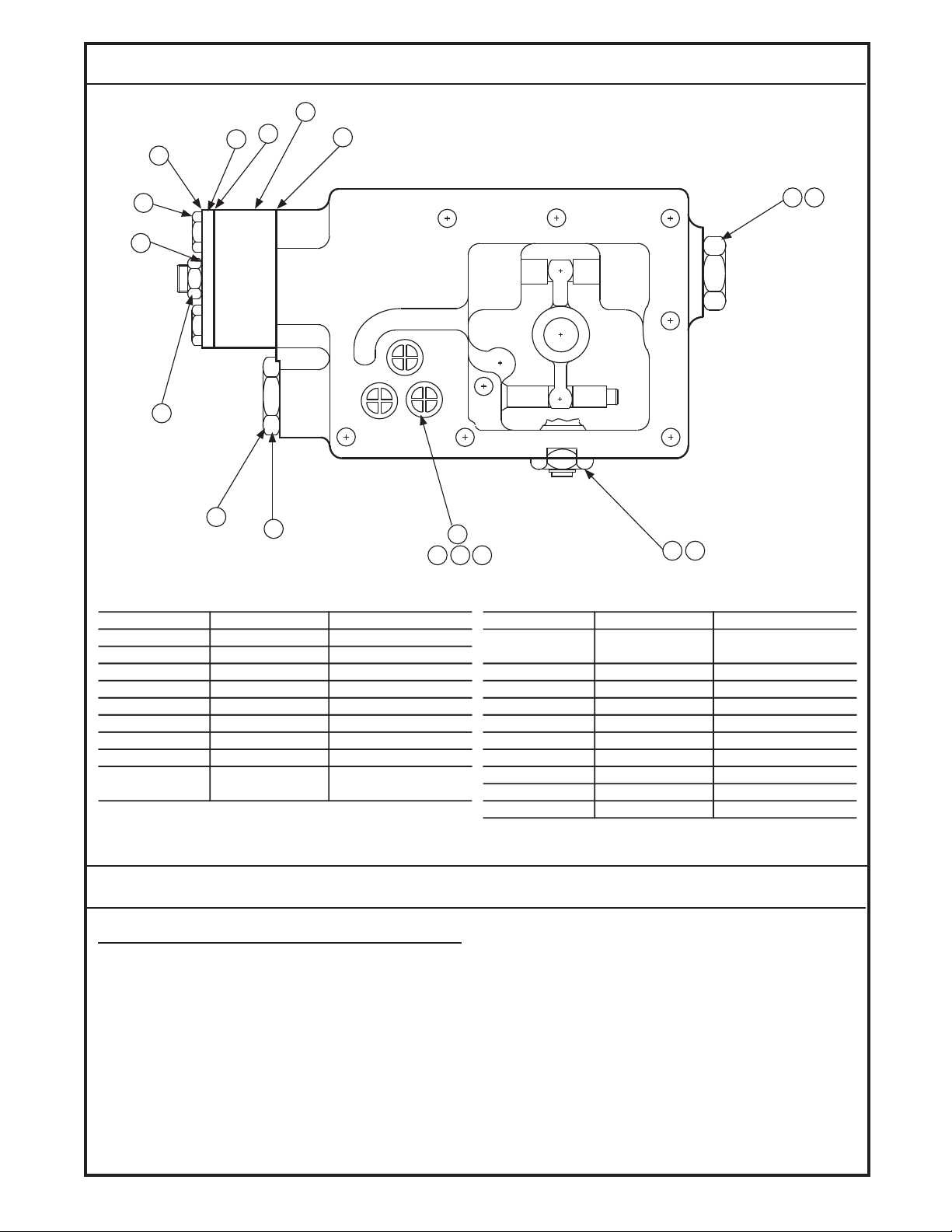
SPARE PARTS
15
10
4
3
14
9
13
8
7
ITEM NUMBER PART NUMBER DESCRIPTION
3 K08621 Cover, Null adjust
9 K07035 Screw, 1/4-20 X 1.5
6
teksaG33180K4
neercS retliF82170K5
gniR-O11070K6
gulP82070K7
23-8/3 ,tuN00070K8
(Spacer models)
5
16 17 18
11 12
1 2
1379
ITEM NUMBER PART NUMBER DESCRIPTION
57.0 X 02-4/1 ,wercS43070K9gniR-O90070K1
)sledom recapS noN(gnihsuB06170K2
10 K07181 Spacer
11 K07159 Plug
12 K07010 O-ring
13 K08387 3/8 Seal washer
14 K08132 Gasket (spacer models)
15 K08601 1/4” Seal washer
16 K07182 HDC gasket
17 K07006 Port O-ring
18 K07136 Orifice
TECHNICAL DATA
HYDRAULIC
OIL VISCOSITY
- 40° to 121° C (-40° to 250° F) operating range
OIL TEMPERATURE
40° TO 121° C (-40 ° TO 250 ° F) operating range
21° to 82 ° C (70° to 180° F) rated performance range 2X Series
21° to 104 ° C (70° to 220 ° F) rated performance range
- 3X Series
MINIMUM SYSTEM FILTRATION
= 2 or better (10 micron nominal)
B
10
© Danfoss, 2014-05 11152454 • Rev AA • May 2014 3
RATED CASE OPERATING PRESSURE
40 psi.
OPERATING CHARGE PRESSURE
150 - 600 psi above case pressure
FLOW RATING
0.7 to 1.1 gpm (std.), 1.2 gpm minimum (annular) total
at saturation with cylinder ports connected and 200 psi
supply pressure.
Page 4

DIMENSIONS
1170B
Dimensions of the MCV106A in Millimeters (Inches).
© Danfoss, 2014-05 11152454 • Rev AA • May 2014 4
Page 5

THEORY OF OPERATION
The HDC uses a unique double spool arrangement that
serves to separate the null deadband from the feedback,
giving both safety against null drift and quick dynamic response to command changes.
The command signal for the MCV106A is usually a remote
hydraulic control handle, as shown in the Block Diagram,
although other pressure sources could be used. The handle
modulates charge pressure from the pump (or another
source) so as to apply a proportional differential pressure
across the C1 and C2 input ports.
The HDC’s null adjust is factory set with the modulating
spring compressed to the equivalent of the threshold pressure (see Technical Data section), depending on the output
characteristics of the command source, representing the
differential pressure required to move the actuator spool one
direction or the other. This is a factory setting that defines the
width of the actuator spool deadband and cannot be changed
in the field. By tightening or loosening the null adjust screw,
the fixed deadband is moved toward or away from a symmetrical neutral position.
As differential control pressure (C1 - C2) rises beyond the
deadband, the actuator spool moves in one direction or the
other, pivoting the crosslink about its center. The pivoting
crosslink pushes or pulls the porting spool in the opposite
direction of the actuator
moved far enough to open A or B to charge pressure, oil is
ported to the pump servocylinders to move the swashplate.
As the swashplate moves, the feedback link follows, pivoting
the crosslink about the stationary end of the actuator spool,
driving the porting spool back toward its neutral position.
Because the feedback signal is entered into the control loop
after the command has been input, response time and
accuracy are enhanced.
INTERNAL WORKINGS SCHEMATIC OF THE MCV106A
spool. When the porting spool has
1171B
Control Handle Supply Pressure May Also Be Provided By an Auxiliary Pilot Pump.
© Danfoss, 2014-05 11152454 • Rev AA • May 2014 5
Page 6

PERFORMANCE
MODULATING RANGE
141 psid (MCV106AXX01)
430 psid (MCV106AXX02)
218 psid (MCV106AXX03)
116 psid (MCV106AXX04)
220 psid (MCV106AXX05)
85 psid (MCV106AXX06)
MAXIMUM HYSTERESIS
4% of modulating range when cycled at .01 Hz
THRESHOLD PRESSURE
12 ± 6.4 psid (MCV106AXX01)
120 ± 15.5 psid (MCV106AXX02)
217 ± 8.1 psid (MCV106AXX03)
44 ± 4.6 psid (MCV106AXX04)
80 ± 8.1 psid (MCV106AXX05)
13 ± 3.5 psid (MCV106AXX06)
SENSITIVITY
A 1%-of-modulating-range change in output differential
pressure will cause a detectable output change.
NEUTRAL LEAKAGE
.10 gpm maximum std., .18 gpm maximum annular
across the valve with 145 - 160 SUS oil @ 38 ° C
(100 ° F)
RESPONSE TIME
See Table C.
DIMENSIONS
See the Dimension drawing.
TABLE C.
MAXIMUM RESPONSE TIME IN SECONDS, OF STANDARD (NON-ANNULAR, NON ORIFICE), ANNULAR AND
.052 ORIFICED HDC'S. CHARGE PRESSURE IS LESS
THAN 250 PSI. RETURN TO NEUTRAL TIMES ARE APPROXIMATELY 60% OF FULL TO FULL.
SERIES TYPE FULL TO FULL
20
20
20
21
21
21
22
22
22
23
23
23
24
24
24
25
25
25
26
26
26
27
27
27
33, 34
33, 34
33, 34
36
36
36
STANDARD
ORIFICED
ANNULAR
STANDARD
ORIFICED
ANNULAR
STANDARD
ORIFICED
ANNULAR
STANDARD
ORIFICED
ANNULAR
STANDARD
ORIFICED
ANNULAR
STANDARD
ORIFICED
ANNULAR
STANDARD
ORIFICED
ANNULAR
STANDARD
ORIFICED
ANNULAR
STANDARD
ORIFICED
ANNULAR
STANDARD
ORIFICED
ANNULAR
.6
1.9
.4
.7
2.1
.5
1.0
2.9
.7
1.0
3.0
.7
1.6
5.0
1.1
1.9
5.7
1.3
4.3
13.0
3.0
4.9
15.1
3.4
.9
1.8
.5
1.4
2.8
.8
ENVIRONMENTAL
SHOCK
50 g for 11 milliseconds. Three shocks in both directions
of the three mutually perpendicular axes for a total of 18
shocks.
VIBRATION
Withstands a vibration test designed for mobile equipment controls consisting of two parts:
1. Cycling from 5 to 2000 Hz in each of the three axes.
© Danfoss, 2014-05 11152454 • Rev AA • May 2014 6
2. Resonance dwell for one million cycles for each
resonance point in each of the three axes.
Subject to acceleration levels of 1 g to 46 g. Acceleration
level varies with frequency.
Page 7

INSTALLATION
WARNING
Danfoss .
TABLE D.
TABLE D CORRELATES THE PUMP SERIES NUMBER
WITH THE SERIES NUMBER STAMPED ON THE SIDE OF
THE FEEDBACK LINK PROTRUDING FROM THE CONTROL.
SERIES LINK MARKING
23 23
bers.
MOUNTING
pump.
REMOVING THE OLD HARDWARE
26 26
SWASHPLATE DRAG LINK
1124B
Swashplate Drag Link/Control Feedback Link Connection Between Original Control and Pump.
© Danfoss, 2014-05 11152454 • Rev AA • May 2014 7
Page 8

MOUNTING THE NEW HARDWARE
1. Re-check the series number on the control feedback link
to ensure that it is compatible with the pump. Follow the
procedure outlined below to install the linkage:
A. Unscrew the bushing, using care not to damage its
O-ring. See the Parts Location photograph.
B. Install the new linkage assembly shaft through the
swashplate feedback shaft hole. Place the ball in
the crosslink ball cavity.
C. Lubricate the shaft O-ring and replace the bushing
over the shaft. Torque to the body (10 - 15 footpounds) so that the feedback shaft extends through
the bushing.
D. Install the retaining ring in the groove on the shaft.
2. Align one end of the replacement drag link with the holes
in the swashplate link arms.
3. Insert the press fit pin through the case drain port to trap
the drag link in the swashplate clevis. It will be necessary
to tap the pin into place until the head of the pin is flush
to the clevis.
SWASHPLATE LOCATION
4. Install the retaining ring by forcing it onto the tapered end
of the pin until it locks into the recess on the pin shaft.
Again, use caution not to drop any components into the
pump housing.
5. One .052 inch diameter orifice must be installed in each
servo port if reduced swashplate response is desired.
6. Engage the pin on the control in the drag link and swing
the control into place against the pump housing. The
drag link should be on the cylinder block side of the
swashplate. Install the seven mounting screws and
tighten to 10 - 11 foot-pounds of torque.
7. Connect the pipe or tubing from the control handle into
the C1 and C2 ports (9/16 - 18 UNF threads per SAE
J514). Phasing of the HDC is such that a pressure rise
at the C2 port causes a pressure rise at the A output port
of the pump, given a clockwise pump prime mover
rotation as viewed into the input shaft.
PIN CONNECTION TO SWASHPLATE
RAG LINK
1126B
Location of Swashplate Assembly in Pump Housing. Shown Disassembled for Clarity.
PARTS LOCATION
LINKAGE ASSEMBLY
SWASHPLATE FEEDBACK
SHAFT HOLE
Location of Parts When Installing a New Link and Ball
CROSSLINK BALL
CAVITY
BUSHING
RETAINING
RING
PUMP PORTS LOCATION
CASE
DRAIN PORT
CHARGE
PRESSURE
GAUGE
PORT
Location of Pump Ports.
Assembly.
1125C
11721173
© Danfoss, 2014-05 11152454 • Rev AA • May 2014 8
Page 9

PUMP NEUTRAL ADJUSTMENT
Use the following procedure to bring the Pump to neutral
once the Hydraulic Displacement Control has been mounted.
1. Install a 600 psi gauge into the charge pressure gauge
port on the pump. See Pump Ports Location photograph.
2. Using 1 9/16 - inch wrench, loosen the hex lock nut on
the null adjustment screw. See Dimensions drawing.
WARNING
To adjust neutral requires operating the pump. Take the
necessary safety precautions such as having unnecessary personnel stand away from the machine. Maximum
system pressure may occur upon start up, and the
machine may move. Ensure that the operator is not in
a position to be injured should the machine move.
3. Set the hydraulic control handle to neutral.
4. Start the prime mover and run at low idle.
5. Warm the system up for several minutes to bleed air.
6. Slowly increase the prime mover speed to rated rpm.
7. If the transmission operates as shown by motor shaft
rotation, reduce speed to idle. Using a 3/16 inch internal
hex wrench, slowly turn the null adjustment screw clockwise or counterclockwise until the transmission does not
operate. Repeat step 6. Note that charge pressure
should drop approximately 20 psi with forward or reverse stroking of the pump swashplate due to the shifting
of the shuttle valve in the motor manifold.
8. With a 3/16-inch internal hex wrench, slowly turn the null
adjustment screw clockwise until charge pressure begins to decrease. Then slowly turn the adjustment screw
counterclockwise, observing the angle of rotation, until
charge pressure decreases again (charge pressure will
rise in neutral and drop when going into stroke).
9. Turn the adjustment screw clockwise half the amount of
the turn observed in step 8. This should be the center of
neutral.
10. Hold the adjustment screw and securely tighten the hex
lock nut on the adjustment screw to 14 - 18 foot-pounds.
Note that if a motor is used which does not have a
manifold, neutral should be adjusted (steps 8 - 10) by
observing the motor output shaft rotation without a load.
11. Stop the prime mover.
12. Run the system briefly to ensure that it operates proportionally on both sides of the null command. Swashplate
movement can be verified by watching movement of the
swashplate feedback shaft, shown in the Dimension
Drawing.
CUSTOMER SERVICE
NORTH AMERICA
ORDER FROM
Danfoss (US) Company
Customer Service Department
3500 Annapolis Lane North
Minneapolis, Minnesota 55447
Phone: (612) 509-2084
Fax: (612) 559-0108
DEVICE REPAIR
For devices in need of repair, include a description of the
problem, a copy of the purchase order and your name,
address and telephone number.
RETURN TO
Danfoss (US) Company
Return Goods Department
3500 Annapolis Lane North
Minneapolis, Minnesota 55447
EUROPE
ORDER FROM
Danfoss (Neumünster) GmbH & Co.
Order Entry Department
Krokamp 35
Postfach 2460
D-24531 Neumünster
Germany
Phone: 49-4321-8710
Fax: 49-4321-871-184
© Danfoss, 2014-05 11152454 • Rev AA • May 2014 9
 Loading...