

Page 1
DESCRIPTION
The MCV102A Pressure Control Servovalve (PCS) is a twostage, fourway, closed loop electrohydraulic servovalve that
provides an output differential pressure in response to a low
power electrical input signal. The PCS consists of a closed
loop Pressure Control Pilot Valve and a closed loop pressure
control boost stage valve. The boost stage valve features a
unique double-spool arrangement that has significant cost
and functional advantages over conventional single-spool
deigns.
The PCS has been designed with an output dynamic
response bandwidth sufficient for most high performance
servo control applications. The valve may be used to directly
control cylinders, to control output forces, or as a first stage
to pilot operated high flow main control valves of 40 gpm to
400 gpm flow rates.
FEATURES
MCV102A
Pressure Control Servovalve
BLN-95-8963-4 Issued: October 1998
• Null shift stability over a wide temperature and pressure
range
• Constant pressure gain regardless of supply pressure,
return pressure and load flow demand changes
• Independent dual spool operation maximizes load flow
output while maintaining proper differential pressure
ORDERING INFORMATION
SPECIFY
• MCV102A1006 (PCS with Packard Connector)
• MCV102A1014 (PCS with MS Connector)
• MCV102A2103 (PCS dual coil MS Connector)
SPARE PARTS
ITEM
NUMBER
1 K01314 Device MS Connector
2 K08106 Mating MS Connector (Bag Assembly)
3 K03377 Device Connector 2-Pin (Unassembled)
4 K03383 Mating Connector 2-Pin (Unassembled)
5 K00829 O-Ring (.364 ID x .070)
6 K00834 O-Ring (1.24 ID x .070)
7 K00830 O-Ring (.43 ID x .070)
8 K04793 Socket head cap screw 10 - 32 X 3/4
9 K00832 0-Ring (.551 ID x .070)
PART
NUMBER DESCRIPTION
• Compatible with standard 10 micron nominal filtration
• Pilot stage manual operator allows hydraulic operation
to be verified without electrical signal
• Configured for direct manifold mounting
• GM Packard or MS Connector available
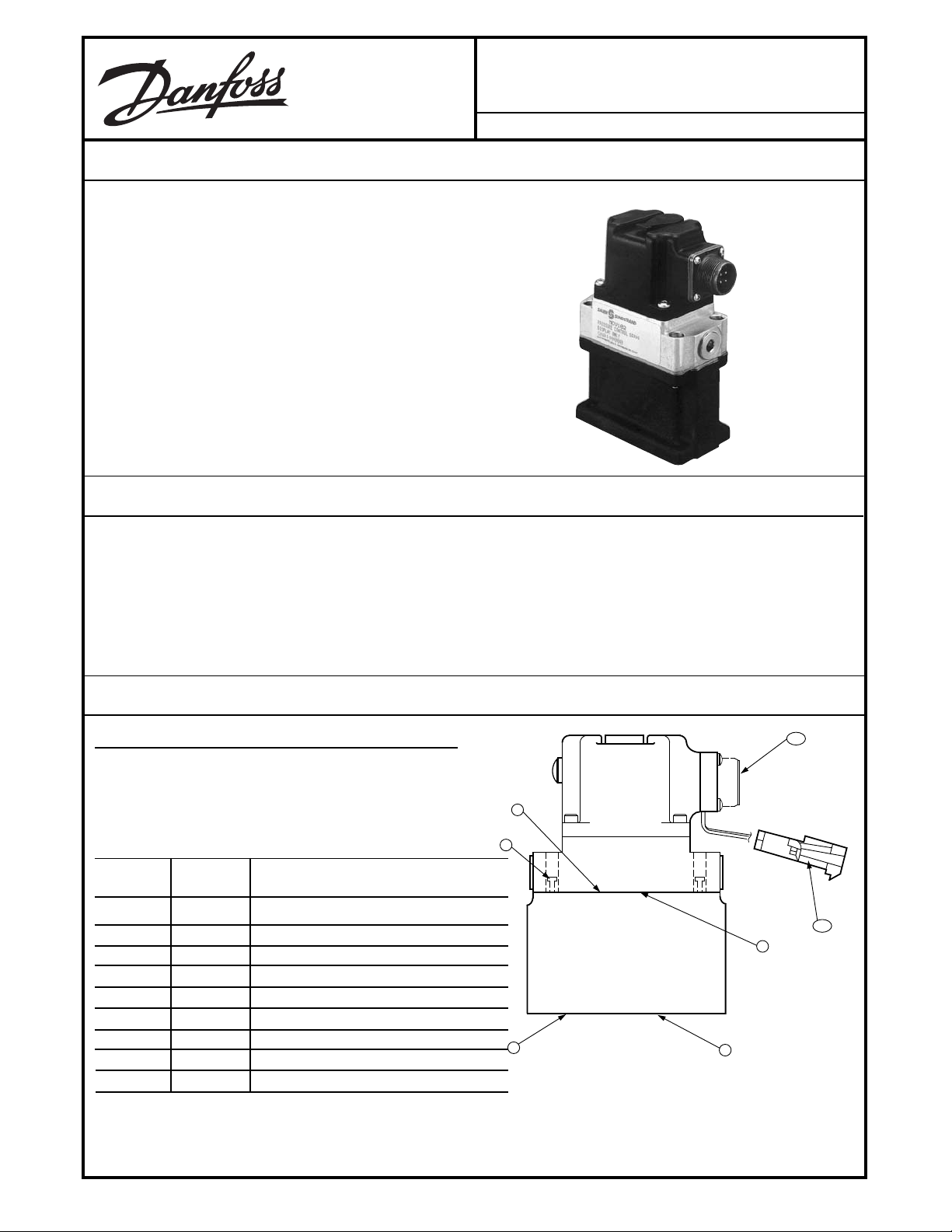
1,2
9
8
3,4
5
7
6
1320A
Location of Spare Parts Item Number.
Mounting manifolds may be made available upon customer request.
© Danfoss, 2013-09 BLN-95-8963-4 1
Page 2
TECHNICAL DATA
ELECTRICAL
RATED FULL PRESSURE CURRENT
See Two Spool, Pressure Control, Static Gain (Single Coil).
±150 mA (single coil ) (23 ohm)
±200 mA (dual coil) (19 and 15.5 ohm)
Maximum input signal is ±250 mA, which will increase
PCS output differential pressure range to approximately
1.2 times that obtained at rated input signal at rated
supply pressure.
COIL RESISTANCE @ 24° C (76° F)
23 ohms (single coil)
19 ohms and 15.5 ohms (dual coil)
COIL INDUCTANCE
.14 Henries (single coil)
.062 Henries (19 ohms, dual coil),
.047 Henries (15.5 ohms, dual coil)
MAXIMUM CONTINUOUS VOLTAGE
7.5 Vdc at 93.3° C (200° F)
HYDRAULIC
FLUID
Petroleum based standard. Other with compatible seals
OIL VISCOSITY
40 - 20,000 SSU
FLUID AND AIR OPERATING TEMPERATURE RANGE
-40° to 104° C (-40° to 220° F)
FLUID AND AIR RATED TEMPERATURE RANGE
-29° to 104° C (-20° to 220° F)
ENVIRONMENTAL
SHOCK
50 G's for 11 milliseconds. Three shocks in both
directions of the three mutually perpendicular axes for a
total of 18 shocks.
VIBRATION
Withstands a vibration test designed for mobile
equipment controls consisting of two parts:
1. Cycling from 5 to 2000 Hz in each of the three axes.
2. Resonance dwell for one million cycles for each
resonance point in each of the three axes.
Subject to acceleration levels of 1 to 46 G's.
Acceleration level varies with frequency.
HUMIDITY
After being placed in a controlled atmosphere of 95%
humidity at 49° C (120° F) for 10 days, the PCS will
perform within specification limits. Meets MIL-STD810B.
PERFORMANCE
LOAD FLOW CURVE
See Two Spool, Pressure Control, Load-Flow Curve
(Single Coil).
SUPPLY PRESSURE
1000 psi maximum
500 psi rated
150 psi minimum
RETURN PRESSURE
Atmospheric to 300 psi
SUPPLY FILTRATION
10 micron nominal recommended
RATED OUTPUT DIFFERENTIAL PRESSURE AT 500 PSI
SUPPLY PRESSURE
±225 psid (23 ohms, single coil)
±156 psid (19 and 15.5 ohms, dual coil)
With output ports blocked
RATED OUTPUT FLOW RATE
6.6 gpm minimum (single coil)
With an output load pressure of 175 psid
.7 gpm minimum (dual coil)
With an output load pressure of 100 psid
TWO SPOOL, PRESSURE CONTROL, STATIC GAIN (SINGLE COIL)
300
200
100
50 100 150 200
CURRENT INPUT (mA)
100
200
300
2
BLN-95-8963-4
OUTPUT
DIFFERENTIAL
PRESSURE (psid)
200 150 100 50
1253A
Page 3
TECHNICAL DATA (continued)
NEUTRAL LEAKAGE
1.2 gpm maximum
Consisting of pilot stage valve quiescent flow plus boost
stage neutral leakage
LINEARITY
Within 5% of rated signal, maximum
Pressure linearity is the deviation from the best straight
line pressure gain curve in either direction expressed as
a percentage of rated input signal. Null region (±4%
OUTPUT PORT NULL PRESSURE
0 psid
With supply pressure at 500 psi above return pressure,
each output port pressure will be 115 psi nominal
signal) pressure gain may vary from 50 to 200% of
nominal pressure gain due to boost stage null
adjustment. Pressure linearity in each direction is
specified from 4% to 90% input signal with a constant
pressure drop across the valve.
THRESHOLD
Less than 1% of rated input signal
SYMMETRY
Will not exceed 5% in each direction
HYSTERESIS
5% of rated input signal, maximum
Symmetry is the difference in output differential
pressure in each direction at rated input signal
expressed as a percentage of the mean output
differential pressure.
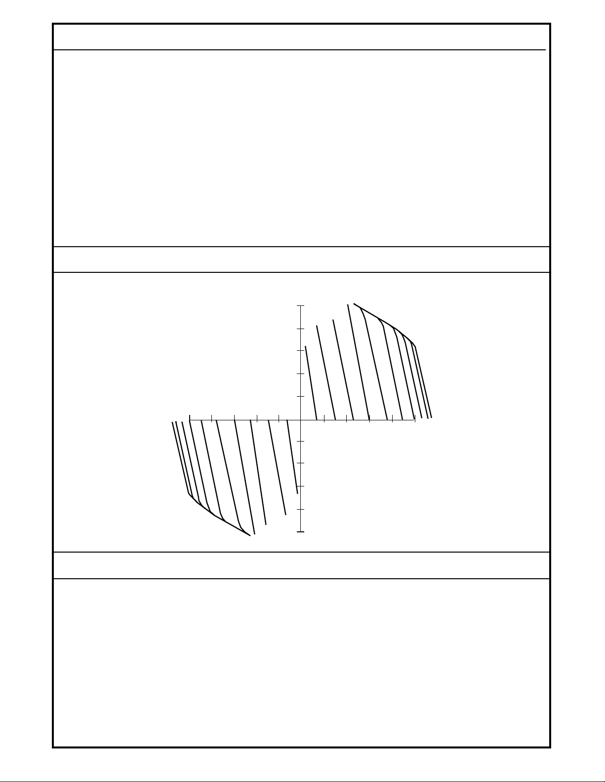
TWO SPOOL, PRESSURE CONTROL, LOAD-FLOW CURVE (SINGLE COIL)
LOW PRESURE VERSION
Pressure control servovalve
Supply pressure: 500 psi
LOAD-FLOW (P-Q) CURVE - PCS
10
FLOW (gpm)
8
175 mA
150 mA
200 mA
250 mA
225 mA
TECHNICAL DATA (continued)
PRESSURE NULL SHIFT
< ±1.5% (23 ohms, single coil)
< ±1.0% (19 and 15.5 ohms, dual coil)
TEMPERATURE NULL SHIFT
< ±3 psid (23 ohms, single coil)
< ±2 psid (19 and 15.5 ohms, dual coil)
125 mA
100150200250
100 mA
75 mA
6
4
2
25 mA
50
2
50 mA
25 mA
4
6
8
10
75 mA
50 mA
50 100 150 200 250
100 mA
125 mA
150 mA
175 mA
200 mA
225 mA
250 mA
1254A
by a current driver-type amplifier. The oil trapped
between the two output ports does not exceed .4 cubic
inches. See Two Spool, Pressure Control, Dynamic
Response.
DIMENSIONS
See Dimensions
FREQUENCY RESPONSE
85 Hz minimum at -3db
70 Hz minimum at 90° phase lag
Specified at 500 psi supply pressure above return
pressure, blocked output ports and an input signal of
±30% to ±50% of rated input signal. The PCS is driven
3
BLN-95-8963-4
Page 4

TWO SPOOL, PRESSURE CONTROL, DYNAMIC RESPONSE
LOW PRESURE VERSION
Pressure control servovalve
±20 mA input
Supply pressure: 500 psi
Differential pressure output
6.00
BODE PLOT
0.00
-6.00
-12.00
-18.00
-24.00
20 x LOG MAGNITUDE
-30.00
– 10 100 1000
FREQUENCY (Hz)
0.00
-30.00
-60.00
-90.00
-120.00
-150.00
PHASE (DEGREES)
-180.00
– 10 100 1000
DIMENSIONS
FREQUENCY (Hz)
1255B
3/8 O.D. TUBE FITTING
O-RING PORT, PER SAE — J514
9/16 — 18 UNF (2) — PL.
(PLUGS INSTALLED)
79,56
(3.12)
140,76 mm ±0.03
(5.52)
61,20
(2.4)
(0.35)
5,64 (DIA.)
(.221)
4 PL.
8,9
NULL
ADJUST
ACCESS
SCREW
85,6
(3.37)
MANUAL
OPERATOR
OPTIONAL MS
CONNECTOR
ELECTRICAL CONNECTOR:
HIGHER POTENTIAL AT
RED LEAD PRODUCES
FLOW OUT C2 TO LOAD,
BACK TO C1.
P = SYSTEM PRESSURE
S
P = RETURN PRESSURE
T
C = OUTPUT CONTROL PORT 1
1
C = OUTPUT CONTROL PORT 2
2
WEIGHT: 1.97 kg (4.33 lbs.)
6,1 (0.24)
19,05
(0.750)
34,9
(1.375)
38,1
(1.50)
116,53 mm ±0.03
(4.57)
BLN-95-8963-4
11,4
(0.450)
38,1
(1.50)
64,77
(2.55)
76,2
(3.0)
Dimensions of the MCV102A PCS in Millimeters (Inches).
4
1284A
Page 5

THEORY OF OPERATION
The MCV102A PCS uses a torque motor actuated, doublenozzle flapper pilot and a double-sliding spool boost stage.
See Internal Workings Schematic. The current input to the
pilot produces a proportional control output differential
pressure to the second stage. The differential pressure is
independent of supply pressure, return pressure and control
characteristics of the valve.
As the electrical input from the command source to the pilot
stage is varied, the pressure signals (P1 and P2) to the boost
stage change, with one increasing and the other decreasing.
This causes the spool to seek a new position, with the higher
INTERNAL WORKINGS SCHEMATIC
POLE
PIECE
AIR GAP
P
S
P1
P1
FLAPPER
ARMATURE
MAGNET
P2
COIL
POLE
PIECE
PIVOT
PLATE
P
S
P2
ORIFICE
NOZZLE
pressure spool moving down and the lower pressure spool
moving up. The new spool position is determined when a
change in the spool land varies the orifice size between
supply pressure and the appropriate work port (A or B),
resulting in a new work pressure (PA or PB). The work
pressure is fed back to the underside of the spool until it
equals the pilot pressure. Spool modulation (which acts like
dither) continues until, at equilibrium, the output differential
pressure is equal to the input differential pressure. Power is
boosted by retaining these pressures at a much higher flow
rate capability.
CONNECTION DIAGRAM
D
C
A
B
1276
P
T
P
Pa
Pa
PORT "A" PORT "B"
Pressure Control Servovalve,Two Spool Design.
P
LOAD
S
Pb
Pb
1292
S
WIRING
Two wiring styles are available: MS and GM Packard
Connectors. The MS Connector is part number MS3108E14S-2S (Danfoss Kit No. K08106) and has four
pins, two of which (A and B) are used. See Pin Orientation of
the Optional MS Connector, Part Number MS3108E-14S-2S
(Danfoss Kit No. K08106). The Packard Connector
a two pin connector. In both cases, phasing is such that
is
a positive voltage on the Red wire (Pin B) will cause a
pressure increase at the C2 port (see Dimensions).
Pin Orientation of 4-pin, 90° MS Mating Connector. Part
No. MS3108E-14S-2S (Danfoss Kit No. K08106).
The Packard Connector PCS includes a bag assembly for
the mating female connector half comprised of:
1. 2, 14-16 gauge sleeves
2. 2, 18-20 gauge sleeves
3. 1 plastic housing
4. 2 green cable seals
5. 2 gray cable seals
6. 2 blue cable seals
See Ordering Information.
To assemble the female mating connector, use the following
directions:
1. Isolate the wires that extend from the command source
to the PCS.
2. Strip back the insulation 5.5 millimeters on both sides.
5
BLN-95-8963-4
Page 6

WIRING (continued)
3. Push ribbed cable seal over each of the wires with the
smaller-diameter shoulder of the seals toward the wire
tip. Select the pair of seals that fits tightly over the wires.
The distance from the tip of the wires to the first (nearest)
rib should be 9.5 millimeters. Thus the installation should
just protrude beyond the seal.
4. Select the larger of the two sets of pins, as measured at
Dimension A (see Dimension A drawing), if using 14-16
gauge wire. Choose the smaller if using 18-20 gauge.
Place the wire into the socket so that the seal edge is
pushed through and extends slightly beyond the circular
tabs that hold it in place. Crimp in the locations shown
in Distance, Packard Connector diagram with a Packard
12014254 crimp tool available from your local Packard
distributor.
DIMENSION A.
5. The distance from the back of the tangs to the furthest
rib may not exceed 19.5 millimeters. See Distance,
Packard Connector diagram.
6. Manually insert the assembled wires into the back end
(large hole) of the plastic housing. Push until the wire
detents with an audible click, then pull back slightly to
ensure proper seating. (Observe the proper phasing of
the wires when installing: Black wire to “A” hole, Red to
“B”.) Terminals may be removed from the connector
bodies with a Packard 12014012 removal tool.
7. Swing the holder down into the detented tower
assembly. The two connector halves should detent into
each other. See Connector Parts Identified, Packard
Connector.
DIMENSION A
Dimension A For Selecting Correct Terminal.
DISTANCE, PACKARD CONNECTOR
CONNECTOR PARTS IDENTIFIED,
PACKARD CONNECTOR
CABLE
SEALS
SIDE "B"
DOUBLE-PLUG SEAL
TOWER CONNECTOR
RED
SIDE "A"
SHROUD
CONNECTOR
1123
BLACK
Distance From Tang to Third Rib of Packard Connector.
BLN-95-8963-4
1077A
1078A
Interlocked Connector Halves With Parts Identified.
Two Wire Connection Shown.
6
Page 7

START UP PROCEDURE
With the electrical connector at the PCS's pilot stage
disconnected, apply hydraulic power to the system. If the load
starts to drift, the PCS is off and will need adjustment. Use a
3/32 inch Allen wrench in the hole covered by the screw in the
pilot cover. Do not exceed more than one turn in either
THROUBLESHOOTING
The most common failure of the pressure control system is
sluggish or no response to electrical command from the
cylinder. If this is the case, follow the procedure below:
Jog the manual operator on the pilot valve. If the cylinder
response is over its full range, disconnect the connector on
the pilot stage. Use a voltohmeter to check the resistance
across pins A and B.
• If the coil resistance is between 22 and 30 ohms, (single
coil) check the resistance between each pin and the
case.
• If the coil resistance is less than 1000 ohms, the pilot coil
is bad and the valve should be replaced.
• If the coil resistance is greater than 1000 ohms, the PCS
is receiving a bad electrical signal. Check the command
source and the connecting cables.
• If the coil resistance is outside the 22 - 30 ohms (single
coil) range, the pilot is bad and the valve should be
replaced.
NORTH AMERICA
ORDER FROM
Danfoss (US) Company
Customer Service Department
3500 Annapolis Lane North
Minneapolis, Minnesota 55447
Phone: (763) 509-2084
Fax: (763) 559-0108
DEVICE REPAIR
For devices in need of repair or evaluation, include a
description of the problem and what work you believe
needs to be done, along with your name, address and
telephone number.
EUROPE
ORDER FROM
Danfoss (Neumünster) GmbH& Co.
Order Entry Department
Krokamp 35
Postfach 2460
D-24531 Neumünster
Germany
Phone: +49 4321 871-0
Fax: +49 4321 871-284
RETURN TO
Danfoss (US) Company
Return Goods Department
3500 Annapolis Lane North
Minneapolis, Minnesota 55447
7
BLN-95-8963-4
 Loading...