

Page 1

MAKING MODERN LIVING POSSIBLE
Operating Instructions
VLT® Factory Tool MCT 21
www.danfoss.com/drives
Page 2

Page 3

Contents Operating Instructions
Contents
1 Introduction
1.1 Purpose of the Manual
1.2 Further Information
1.3 Product Overview
1.4 Document and Software Version
2 Safety
2.1 Safety Symbols
2.2 Qualified Personnel
2.3 Safety Precautions
3 Installation and Set-up
3.1 Installation
3.2 De-installation
3.3 Set-up
4 Workflow
4.1 Interaction of Engineering Tool and Technician Tool
3
3
3
3
3
4
4
4
4
6
6
6
6
7
7
4.2 Workflow Engineering Tool
4.3 Workflow Technician Tool
5 Engineering Tool Functions
5.1 Project
5.1.1 Create a Project 10
5.1.2 New Project - Create from Database 10
5.1.3 New Project - Read from Drive 12
5.1.4 Open Project 12
5.1.5 Search Project 13
5.1.6 Create Order 13
5.1.7 Copy Project 15
5.1.8 Upgrade a Project to New Firmware 16
5.2 Motor Database
5.3 Motor Library
5.3.1 Common Motor Library 19
5.3.2 Export Library 21
5.3.3 Copy the Common Motor Library 21
8
9
10
10
17
19
5.4 SIVP (Specific Initial Values and Protection)
5.4.1 Define the SIVP 22
5.4.2 SIVP Examples 24
5.4.3 Copy SIVP Library 25
MG10X102 Danfoss A/S © Rev. 2014-06-09 All rights reserved. 1
22
Page 4

Contents Operating Instructions
5.5 Tests
5.5.1 Create Test 25
5.5.2 Edit Test 26
5.5.2.1 Commands 26
5.5.2.2 Editing Procedure 27
5.5.3 Control Word according to FC Profile (CTW) 28
5.5.4 Definition of Reference 30
5.5.5 Select and Run Test, View Test Report 30
5.5.6 Remove Test 30
5.5.7 Copy Test 31
5.6 Settings Menu
5.6.1 General Settings 32
5.6.2 Drive Communication 32
6 Technician Tool Functions
6.1 Project
6.1.1 Open a Project 33
6.1.2 Project View 33
25
32
33
33
6.2 Motor Database
6.3 SIVP
6.4 Tests
Index
6.1.3 Project Review and Adjustments 33
6.1.4 Create an Order 34
6.1.5 Write to Frequency Converter 34
6.1.6 Compare 35
35
35
6.3.1 Select 35
6.3.2 Write to Frequency Converter 35
35
6.4.1 Test and Documentation 35
37
2 Danfoss A/S © Rev. 2014-06-09 All rights reserved. MG10X102
Page 5

Introduction
1 Introduction
Operating Instructions
1
1
1.1 Purpose of the Manual
This manual provides basic knowledge required to use the
VLT® MCT 21 Factory Tool with VLT® DriveMotor FCP 106
and FCM 106 frequency converters.
Familiarity with the following is assumed:
MS®-WindowsTM at user level.
•
Set-up, process knowledge, and operation of
•
frequency converters.
Connection, set-up, and use of communication
•
equipment.
Familiarity with the PC or PLC master of the
•
system.
Issues regarding hardware or software produced by other
manufacturers are beyond the scope of this manual, and
are not the responsibility of Danfoss.
The manual does not provide detailed information
regarding:
Specific applications
•
Possible solutions
•
Related parameter combinations in the set-up
•
and use of a frequency converter.
1.3
Product Overview
1.3.1 Intended Use
The MCT 21 Factory Tool enables the creation of factory
settings and testing of the frequency converter in the
factory. The software comprises 2 tools:
Engineering Tool
•
Technician Tool
•
For details of the interaction of these tools, refer to
chapter 4.1 Interaction of Engineering Tool and Technician
Tool.
System Requirements
1.3.2
Supported operating systems:
Windows 7 (32 bit) Service Pack 1
•
Windows 7 (64 bit) Service Pack 1
•
Windows XP (32 bit) Service Pack 3
•
Additional system requirements:
Minimum screen resolution: 1024 × 768
•
Minimum physical memory: 256 MB
•
Communication bus: Danfoss FC protocol on
•
RS-485
VLT® is a registered trademark.
1.2
Further Information
Literature available:
VLT® DriveMotor FCP 106 and FCM 106 Operating
•
Instructions
VLT® DriveMotor FCP 106 and FCM 106
•
Programming Guide
VLT® DriveMotor FCP 106 and FCM 106 Design
•
Guide
The full range of manuals, instructions, and software
downloads is available at:
http://www.danfoss.com/BusinessAreas/DrivesSolutions
Prerequisite installed software:
VLT® Motion Control Tool MCT 10 software. MCT
•
21 Factory Tool uses the parameter database
from MCT 10.
1.4
Document and Software Version
This manual is regularly reviewed and updated. All
suggestions for improvement are welcome. Table 1.1 shows
the document version and the corresponding MCT 21
Factory Tool software version.
Edition Remarks
MG10X1 New document 1.20 and later versions
Table 1.1 Document and Software Version
MCT 21 Factory Tool software
version
MG10X102 Danfoss A/S © Rev. 2014-06-09 All rights reserved. 3
Page 6

Safety
Operating Instructions
2 Safety
22
2.1 Safety Symbols
The following symbols are used in this document:
WARNING
Indicates a potentially hazardous situation which could
result in death or serious injury.
CAUTION
Indicates a potentially hazardous situation which could
result in minor or moderate injury. It can also be used to
alert against unsafe practices.
NOTICE
Indicates important information, including situations that
can result in damage to equipment or property.
2.2 Qualified Personnel
Correct and reliable transport, storage, installation,
operation, and maintenance are required for the troublefree and safe operation of the frequency converter. Only
qualified personnel are allowed to install or operate this
equipment.
Qualified personnel are defined as trained staff, who are
authorised to install, commission, and maintain equipment,
systems, and circuits in accordance with pertinent laws and
regulations. Additionally, the personnel must be familiar
with the instructions and safety measures described in
these operating instructions.
2.3
Safety Precautions
WARNING
HIGH VOLTAGE
Frequency converters contain high voltage when
connected to AC mains input power. Failure to perform
installation, start up, and maintenance by qualified
personnel could result in death or serious injury.
Only qualified personnel are permitted to
•
perform installation, start up, and maintenance.
WARNING
UNINTENDED START
When the frequency converter is connected to AC mains,
DC power supply, or load sharing, the motor can start at
any time. Unintended start during programming, service,
or repair work can result in death, serious injury, or
property damage. The motor can start with an external
switch, a fieldbus command, an input reference signal
from the LCP or LOP, via remote operation using a
software tool, or after a cleared fault condition.
To prevent unintended motor start:
Disconnect the frequency converter from mains.
•
Press [Off/Reset] on the LCP before
•
programming parameters.
Ensure the frequency converter, motor, and any
•
driven equipment are fully wired and
assembled when the frequency converter is
connected to AC mains, DC power supply, or
load sharing.
WARNING
DISCHARGE TIME
The frequency converter contains DC-link capacitors,
which can remain charged even when the frequency
converter is not powered. Failure to wait the specified
time after power has been removed before performing
service or repair work could result in death or serious
injury.
Stop the motor.
•
Disconnect AC mains and remote DC-link power
•
supplies, including battery back-ups, UPS, and
DC-link connections to other frequency
converters.
Disconnect or lock the PM motor.
•
Wait for the capacitors to discharge fully before
•
performing any service or repair work. The
duration of waiting time is specified in
Table 2.1.
Minimum waiting
[kW]
1)
time
(min)
Voltage
[V]
3x400 0.55–7.5 4
High voltage can be present even when the warning LED
Power range
indicator lights are off.
Table 2.1 Discharge Time
1) Power ratings relate to normal overload (NO).
4 Danfoss A/S © Rev. 2014-06-09 All rights reserved. MG10X102
Page 7

Safety Operating Instructions
WARNING
EQUIPMENT HAZARD
Contact with rotating shafts and electrical equipment
can result in death or serious injury.
Ensure that only trained and qualified
•
personnel perform installation, start up, and
maintenance.
Ensure that electrical work conforms to national
•
and local electrical codes.
Follow the procedures in this manual.
•
WARNING
UNINTENDED MOTOR ROTATION
WINDMILLING
Unintended rotation of permanent magnet motors can
result in serious injury or equipment damage.
Ensure that permanent magnet motors are
•
blocked to prevent unintended rotation.
WARNING
LEAKAGE CURRENT HAZARD
Follow national and local codes regarding protective
earthing of equipment with a leakage current exceeding
3.5 mA. Frequency converter technology implies high
frequency switching at high power. This switching
generates a leakage current in the ground connection. A
fault current in the frequency converter at the output
power terminals can contain a DC component which can
charge the filter capacitors and cause a transient ground
current. The ground leakage current depends on various
system configurations including RFI filtering, screened
motor cables, and frequency converter power. EN/IEC
61800-5-1 (Power Drive System Product Standard)
requires special care because the leakage current
exceeds 3.5 mA. See EN 60364-5-54 paragraph 543.7 for
further information.
Ensure correct grounding of the equipment by
•
a certified electrical installer.
Grounding must be reinforced in one of the
•
following ways:
- Ensure the ground wire has a crosssection of at least 10 mm2, or
- Ensure 2 separate ground wires, both
complying with the dimensioning
rules, are used.
NOTICE
HIGH ALTITUDES
For installation at altitudes above 2000 m, contact
Danfoss regarding PELV.
WARNING
DC CURRENT RISK
This product can cause a DC current in the protective
conductor. Failure to follow the precautions can lead to
personal injury or property damage.
Take the following precautions:
Where a residual current device (RCD) is used
•
for extra protection, use only an RCD of Type B
(time delayed) on the supply side of this
product.
Protective earthing of the frequency converter
•
and the use of RCDs must always follow
national and local regulations.
WARNING
GROUNDING HAZARD
For operator safety, it is important to ground the
frequency converter properly in accordance with national
and local electrical codes, as well as the instructions in
this manual. Ground currents are higher than 3.5 mA.
Failure to ground the frequency converter properly could
result in death or serious injury.
It is the responsibility of the user, or certified electrical
installer, to ensure correct grounding of the equipment
according to national and local electrical codes and
standards.
Follow all local and national electrical codes to
•
ground electrical equipment properly.
Establish proper protective grounding for
•
equipment with current higher than 3.5 mA.
A dedicated ground wire is required for input
•
power, motor power, and control wiring.
Use the clamps provided on the equipment for
•
proper ground connections.
Do not ground one frequency converter to
•
another in a daisy chain fashion.
Keep the ground wire connections as short as
•
possible.
Use high-strand wire to reduce electrical noise.
•
Follow the motor manufacturer wiring
•
requirements.
2 2
MG10X102 Danfoss A/S © Rev. 2014-06-09 All rights reserved. 5
Page 8

Installation and Set-up Operating Instructions
3 Installation and Set-up
3.1 Installation
33
Prerequisite: MCT 10 Set-up Software is installed.
To install the MCT 21 Factory Tool,
1.
Run the file MCT 21 Factory Tool Setup x.x.exe,
where “x.x” refers to the software version. No key
is required.
2. Select during installation:
2a Technician Tool, and/or
2b Engineering Tool
3. Open the programme.
3.3.2 Serial Fieldbus Communication
To set up serial fieldbus communication with the
frequency converter, refer to chapter 5.6.2 Drive Communi-
cation.
3.2 De-installation
NOTICE
De-installation procedure for a Windows operating
system:
1.
Select Start.
2.
Select Settings.
3.
Select Control Panel.
4.
Double-click Programs and Features.
5. Select MCT 21 Factory Tool software.
6.
Select Uninstall.
3.3
Set-up
3.3.1 General Settings
For detailed information regarding general settings, refer
to chapter 5.6.1 General Settings.
Open the MCT 21 Factory Tool software.
•
The first time the program runs, the New Project
•
dialog appears. For more information, see
chapter 5.1.2 New Project - Create from Database.
Go to [Settings → General Settings].
•
In the General Settings dialog:,
•
Set the application and parameter
-
languages.
Set the OEM password.
-
NOTICE
PASSWORD MATCH
Note that data can be password-protected in the
frequency converter. Set the OEM password to match the
frequency converter password. Otherwise no access is
granted.
6 Danfoss A/S © Rev. 2014-06-09 All rights reserved. MG10X102
Page 9

Workflow
Operating Instructions
4 Workflow
4.1 Interaction of Engineering Tool and
Technician Tool
The MCT 21 Factory Tool software comprises 2 tools which
interact:
Engineering Tool
•
Technician Tool
•
Develop projects and tests in the Engineering Tool before
implementation in the Technician Tool.
Engineering Tool - Development
The Engineering Tool is intended for use by engineers in
developing projects and tests for planning factory
implementation of frequency converter default settings.
The engineer uses the Engineering Tool to:
Create projects.
•
Set up default parameter settings for OEM
•
production.
Create, design, and verify tests.
•
Manage passwords, motor database, general
•
settings, and communication with the frequency
converter.
Process orders received.
•
Access change and test logs.
•
For Engineering Tool workflow, refer to
chapter 4.2 Workflow Engineering Tool.
For details of Engineering Tool functions, refer to
chapter 5 Engineering Tool Functions.
Technician Tool - Implementation
The Technician Tool is intended for use by technicians
working in the production line. The technician is familiar
with how to assemble the frequency converter and motor.
The technician uses the Technician Tool to:
Create custom set-ups for the frequency
•
converter.
Configure the frequency converter with new
•
settings.
Select and run tests.
•
Manage communication with the frequency
•
converter.
The technician uses projects and tests developed in the
Engineering Tool.
For Technician Tool workflow, refer to chapter 4.3 Workflow
Technician Tool.
For details of Technician Tool functions, refer to
chapter 6 Technician Tool Functions.
4 4
MG10X102 Danfoss A/S © Rev. 2014-06-09 All rights reserved. 7
Page 10

Workflow Operating Instructions
4.2 Workflow Engineering Tool
44
Illustration 4.1 Engineering Tool Workflow
For details of each step refer to the following:
Chapter 5.1.1 Start
•
Chapter 5.1.1 Create a Project
•
Chapter 5.1.4 Open Project and chapter 5.1.5 Search Project
•
Chapter 5.4.1 Define the SIVP
•
Chapter 5.2.1 Define a Motor Database
•
Chapter 5.3.1 Common Motor Library
•
Chapter 5.3.2 Common Motor Library Management
•
Chapter 5.5.5 Select and Run Test, View Test Report
•
Chapter 5.5.1 Create Test and chapter 5.5.2 Edit Test
•
8 Danfoss A/S © Rev. 2014-06-09 All rights reserved. MG10X102
Page 11

Workflow Operating Instructions
4.3 Workflow Technician Tool
4.3.1 Overview of Workflow
4 4
Illustration 4.2 Technician Tool Workflow
For details of each step refer to the following:
Step 1: chapter 6.1.2 Project View
•
Step 2 (optional): chapter 6.1.3 Project Review and Adjustments
•
Alternative to Step 2: chapter 5.1.6 Create Order
•
Step 3: chapter 6.1.5 Write to Frequency Converter
•
Step 4 (optional): chapter 6.1.6 Compare
•
Step 5: chapter 6.4.1 Test and Documentation
•
Programme the next frequency converter with the same settings: see chapter 5.3.1 Common Motor Library
•
A test report is created: see
•
chapter 5.5.5 Select and Run Test, View Test Report
-
chapter 6.4.1 Test and Documentation
-
Details are stored in a log file: see chapter 5.5.5 Select and Run Test, View Test Report.
•
MG10X102 Danfoss A/S © Rev. 2014-06-09 All rights reserved. 9
Page 12

Engineering Tool Functions Operating Instructions
5 Engineering Tool Functions
5.1 Project
Create a Project
5.1.1
Initial start
At initial startup of the Engineering Tool, the New Project
dialog opens, see Illustration 5.1. No projects have
previously been created. For details of how to create a
new project, go to chapter 5.1.1 Create a Project.
55
Illustration 5.1 New Project Dialog
A project contains a set of motors and tests available for
use by the technician. Use the Engineering Tool to create a
project.
There are 2 starting points for creating a new project:
Based on an MCT 10 database. Follow the steps
•
in chapter 5.1.2 New Project - Create from
Database.
Based on a project stored in a frequency
•
converter. Follow the steps in chapter 5.1.3 New
Project - Read from Drive.
When all the steps are completed, the new project opens
in project view. See chapter 5.1.6 Project View.
New Project - Create from Database
5.1.2
To create a new project based on the MCT 10 database:
1.
Select Projects in the menu bar.
2. Via the dropdown menu, go to [Projects → New
Project → Create from database], as shown in
Illustration 5.3.
Subsequent start
At subsequent startup of the Engineering Tool, the Search
dialog opens, see Illustration 5.2. Use the dialog to search
for existing projects. For more information go to
chapter 5.1.5 Search Project.
Illustration 5.2 Search Dialog
Illustration 5.3 Path for New Project Based on MCT 10
Database
10 Danfoss A/S © Rev. 2014-06-09 All rights reserved. MG10X102
Page 13

Engineering Tool Functions Operating Instructions
3.
The New Project dialog opens, see Illustration 5.4.
Illustration 5.4 New Project Dialog
4.
Enter or select project details, see Illustration 5.5:
4a Project name
4b Frequency converter (“Drive series”)
4c Power size
4d Voltage
4e Basic SW version
4f Parameter language
Click on [Create Project]
5.
The Project Info dialog opens. Enter further details
of the project, as shown in the example, see
Illustration 5.6.
Illustration 5.6 Project Info Dialog
NOTICE
There are 2 dialogs containing information about the
customer and the order: Project Info (see Illustration 5.6)
and Test Drive and Motor (see Illustration 5.37). Ensure
the data in both dialogs are consistent.
NOTICE
To adapt the Project Info content subsequently, ensure
the original file is preserved, not overwritten. Use Save
As when adapting content to a different project.
5 5
6. Click on [Save].
7. The new project opens.
8. A confirmation message appears, stating that the
new project is now created, see Illustration 5.7.
Illustration 5.7 Project Created
Illustration 5.5 New Project, Selection Drop Down Menu
MG10X102 Danfoss A/S © Rev. 2014-06-09 All rights reserved. 11
Page 14

Engineering Tool Functions
Operating Instructions
5.1.3 New Project - Read from Drive
Use of an existing project stored in a frequency
converter
To import an existing project from a frequency converter
to MCT 21 Factory Tool, use Read From Drive. The Read
From Drive function enables project transfer from the
frequency converter memory to the PC.
NOTICE
PASSWORD MATCH
Note that data may be password protected in the
55
frequency converter. Set the MCT 21 Factory Tool
password defined in [Settings → General Settings], to be
identical with the frequency converter password.
Otherwise no access is granted.
To create the project:
1.
Select Projects in the menu bar.
2. Via the dropdown menu, go to [Projects → New
Project → Read From Drive]. See the dropdown
menu in Illustration 5.3.
3.
The Read From Drive dialog opens, see
Illustration 5.8.
6. The data transfers from the frequency converter
to MCT 21 Factory Tool, and the new project
opens.
When selecting Read from Drive, a commutation must be
established. Then project information can be extracted
from the frequency converter. See the note on password
match requirements.
5.1.4 Open Project
To open an existing project, go to [Projects → Open
Project]. The browser opens. Select the project in the
folder structure, and click [Open]. The Project Info dialog
opens, see Illustration 5.9.
Illustration 5.8 Read From Drive
4. If communication with the frequency converter is
not possible, click Configure Communication, to
adjust the settings. To access the communication
configuration later, go to [Settings → Drive
Configuration].
5. Click [Read From Drive].
Illustration 5.9 Open Project, Project Info Dialog
The Project Info dialog differs from that for a new project.
For an existing project, the Project Info dialog contains a
[Save As] button. Use [Save As] to create a new project on
the basis of a copy of an existing project.
When changing the Project Info settings, use the [Save As]
button to ensure the existing project is not overwritten.
When entering new settings, clicking on [Save] will cause
the previous settings to be overwritten, and the previously
existing project will be deleted.
12 Danfoss A/S © Rev. 2014-06-09 All rights reserved. MG10X102
Page 15

Engineering Tool Functions Operating Instructions
5.1.5 Search Project
Access the search dialog via [Menu → Search Project].
Illustration 5.11 Project View: Example of New Project
Illustration 5.10 Search Dialog
Use the Search dialog to find an existing project. The
existing projects originate from the Engineering Tool, see
chapter 5.1.1 Create a Project.
Search for all projects
To display a list of all existing projects:
1. Click on [Show All].
2. The search results are displayed in the field
Search Result.
Search with filter
To display a list containing only a selection of the existing
projects:
1. Set the search criteria
1a To search for a specific project, use the
fields Customer Name and Application
Name.
1b To filter for specific properties of the
frequency converter or motor, fill out
the fields under Drive Information and
Motor Information.
2. Click on [Search project].
3. The search results are displayed in the field
Search Result.
The new project opens in the project view, see example in
Illustration 5.11.
The project name appears in the horizontal menu bar. In
the example the project name is Database, see
Illustration 5.11.
The left panel contains the project structure, for setting up
and accessing data in the project. Unfold the structure to
view the elements:
Motors
•
SIVP
•
Test
•
Initially there is no data in the project , so the 3 elements
have the suffixes Empty and 0.
To enter and import data into the project, see:
Chapter 5.2.1 Motor Database
•
Chapter 5.4 SIVP (Specific Initial Values and
•
Protection)
Chapter 5.5.1 Create Test
•
Chapter 5.1.6 Create Order
•
Create Order
5.1.6
A third way to create a project, is via an order file. The
order file specifies project data, including SIVP parameters
and motor database. To create the order, use an external
order handling tool.
Orders
MCT 21 Factory Tool monitors the order folders. The
location of the order folder is specified under General
Settings, see chapter 5.6.1 General Settings. New orders are
indicated in the menu bar, as shown in Illustration 5.12.
5 5
Illustration 5.12 New Order shown in Menu Bar
MG10X102 Danfoss A/S © Rev. 2014-06-09 All rights reserved. 13
Page 16

Engineering Tool Functions Operating Instructions
Unprocessed Orders
When a user places an order file, it is listed in [Orders →
Unprocessed Orders], see Illustration 5.13.
Processed Orders
Processed orders are listed in [Orders → Processed Orders],
see Illustration 5.15.
55
Illustration 5.13 Unprocessed Orders Dialog
To select and open the order,
1.
Mark the checkbox under Select
2. Click on [Process]
3. When processing the order, the order converts
into a project, which can be saved to the
frequency converter, see Illustration 5.14.
Illustration 5.15 Processed Orders Dialog
Order file
An order file of processed orders is maintained in the
Order folder. The location of the order folder is specified
under General Settings, see chapter 5.6.1 General Settings.
For the structure of the order file, see Table 5.1.
Content
1)
Comment
Line
1 Order number Mandatory item
Illustration 5.14 Order Converts into Project: Project Info
Dialog
2 OEM name Optional item, can be
empty.
3 OEM type code Optional item, can be
empty.
4 OEM identity Optional item, can be
empty.
5 OEM application name Optional item, can be
empty.
6 Customer name Optional item, can be
empty.
7 Drive series Mandatory item: FCP106 or
FCM 106
8 Drive software If empty, reverts to default
(most recent software
version).
9 Drive power Mandatory item. Example:
1.50
10 Drive voltage Mandatory item. Example:
380-480
11 Language If empty or invalid, reverts
to default (English).
12 Master file Optional item, can be
empty.
The master file is an MCT 21
file containing for example
MotorDB, Pump DB, and
SIVP (or parts of it).
13 Number of parameters
defined in the following
lines
-
14 Danfoss A/S © Rev. 2014-06-09 All rights reserved. MG10X102
Page 17

Engineering Tool Functions Operating Instructions
Line
x Parameter ID, Array index,
y Order file status 0 = processed
Table 5.1 Structure of an Order File
1) Value separator is defined as - or ; or |.
1)
Content
Setup, Value, Read-Only,
Visibility – it can be empty.
Comment
Optional item, can be empty
If Parameter ID is already in
use by master file, it
overwrites its value.
1 = unprocessed
Note that text starting with /* and ending with */ will be
ignored, and can be used for comments. See Table 5.2 for
an order file example.
Line
1 Test Order 1 /*ORDER NUMBER – it must exist*/
2 OrderName /*OEM NAME – it can be empty also*/
3 A412 /*OEM TYPE CODE – it can also be empty*/
4 TEST /*OEM IDENT– it can also be empty*/
5 MCT21 /*APPLICATION NAME – it can also be empty*/
6 Danfoss /*CUSTOMER NAME– it can also be empty*/
7 FCP106 /*DRIVE SERIES – it must exist*/
8 01.10 /*SW Version. If empty it will take the latest
9 1.50 /*drive power – must exist*/
10 380-480 /*Voltage – must exist*/
11
12 English /*parameter language if empty or wrong it
13 /*MCT21 file from where we can extract MotorDB file,
14 3 /*Number of parameters – can be zero*/
x 1;0;2;1;1;1 /*Parameter ID, Array index, Setup, Value,
x 100;0;1;3;0;1 /*parameter is Configuration Mode, array
x 207;0;1;8.5;1;1 /*parameter is Parking Time, array index
y 1 /* Order is unprocessed */
1)
Content
one*/
must default to */
Pump DB location, and SIVP file – can be empty –
called master file*/
Read-Only, Visibility – it can be empty. In case of
Parameter ID already in use by master file, it
overwrites it’s value.*/
index 0, setup 1, value 3 (Closed Loop), will be read
and write, and not visible*/
0, setup 2, value 8.5, will become read-only and not
visible*/
5.1.7
Copy Project
Copy all project data
To copy all project data from one PC to another:
1. Open Windows Explorer.
2. Open the project folder.
2a To find the project folder go to [Menu
→ General Settings].
2b The project folder is displayed in the
field Projects folder, as shown in
Illustration 5.16.
2c The default project folder is
C:\ProgramData\Danfoss Power
Electronics\MCT21 Factory Tool\Projects\.
3. Copy the entire project folder content to a
suitable storage media, for example a USB stick.
4. Open the test folder.
4a To find the test folder, go to [Menu →
General Settings].
4b The test folder is displayed in the field
Tests folder, as shown in Illustration 5.16.
4c The default test folder is:
C:\ProgramData\Danfoss Power
Electronics\MCT21 Factory Tool\Projects\.
5. Copy the entire test folder content to a suitable
storage media, for example a USB stick.
6. Move the media to the destination PC.
7. Copy the files from the source project and test
folders to the corresponding folders on the
destination PC.
5 5
Table 5.2 Example of an Order File
1) Value separator is defined as - or ; or |.
Illustration 5.16 General Settings Dialog, showing the Projects
Folder
MG10X102 Danfoss A/S © Rev. 2014-06-09 All rights reserved. 15
Page 18

Engineering Tool Functions Operating Instructions
5.1.8 Upgrade a Project to New Firmware
When new frequency converter firmware is released, a
project may require upgrade to the new firmware.
There are 2 methods to upgrade a project to new
firmware.
Upgrade method 1
1. Create a new project with the new firmware.
2. Import the motors.
55
3. Import the .siv files from the old project.
4. Select the required tests.
5. The new project is now ready for use.
For more information, see chapter 5.1.1 Create a Project.
Upgrade method 2
1. Open Windows Explorer.
2. Open the project folder.
2a To find the project folder go to [Menu
→ General Settings].
2b The project folder is displayed in the
field “Projects folder”, as shown in
Illustration 5.16.
2c
The default project folder is C:
\ProgramData\Danfoss Power Electronics
\MCT21 Factory Tool\Projects\.
3. Create a copy of the project file. The project file
has the suffix .xml.
4. Open a new file in the text editor.
5. In the text editor, change the content of the tag
<BasicSoftwareVersion>1.10</BasicSoftwareVersion> to the new firmware version, as shown
in Illustration 5.17.
6. Save and close the text editor file.
7. The project is now upgraded to the new firmware
version, and is ready for use.
Illustration 5.17 Basic Software Version Tag in the Text Editor
16 Danfoss A/S © Rev. 2014-06-09 All rights reserved. MG10X102
Page 19

Engineering Tool Functions
Operating Instructions
5.2 Motor Database
For each project, define a motor database, see Illustration 5.18.
To populate the motor database, import motors from the motor library, see chapter 5.3 Motor Library. For more information,
refer to chapter 5.2 Motor Database.
5 5
Illustration 5.18 Project Motor Database
To view motors available to a project, open the Motor Database:
1.
Go to the Project Viewvia [Projects → Open Project] or [Projects → New Project].
2.
Click the Motors element in the project structure.
The Project Motor Database dialog opens, see Illustration 5.19.
Illustration 5.19 Project Motor Database
The Project Motor Database dialog displays a list of motors available to the project, including details of motor characteristics.
MG10X102 Danfoss A/S © Rev. 2014-06-09 All rights reserved. 17
Page 20

Engineering Tool Functions Operating Instructions
Add a motor to the database
To add a motor to the motor database:
1.
Open the Common Motor Library. For instructions see chapter 5.3.1 Common Motor Library.
2.
Open the Project Motor Database dialog, see Illustration 5.19.
3.
Click [Motor Library]. The Common Motor Library dialog opens.
4.
Select motors from the Common Motor Library. For more information, refer to chapter 5.3.1 Common Motor Library.
5. Place a checkmark to select which motors to add to the project.
6. Click [Copy motor(s) to project].
7. Click [Save].
55
Illustration 5.20 Project Motor Database
Remove a motor from the database
To remove a motor from the Project Motor Database:
1. Click on [Remove] for the motor in the list.
2. Click on [Save].
18 Danfoss A/S © Rev. 2014-06-09 All rights reserved. MG10X102
Page 21

Engineering Tool Functions Operating Instructions
5.3 Motor Library
5.3.1 Common Motor Library
The Common Motor Library contains a list of all motors available for use in all projects, including motor characteristics for
each. Use the Common Motor Library to find suitable motors for each project, and import them into the project.
5 5
Illustration 5.21 Motor Library, Example
Open the Common Motor Library
To open the Common Motor Library,
1. In the menu bar, go to [Tools → Common Motor Library.]
2.
The Management Common Motor Library dialog opens, see Illustration 5.21.
MG10X102 Danfoss A/S © Rev. 2014-06-09 All rights reserved. 19
Page 22

Engineering Tool Functions Operating Instructions
Create a new motor
To add a motor to the Common Motor Library:
1. Select [Add New Motor].
2.
The Create New Motor dialog opens, see Illustration 5.22.
3. The dialog contains preselected data, which are based on the MCT 10 database. Depending on the motor type,
some fields are not accessible.
4. Select and/or enter the type and characteristics of the motor, then save.
55
Illustration 5.22 Create New Motor Dialog, Example
20 Danfoss A/S © Rev. 2014-06-09 All rights reserved. MG10X102
Page 23

Engineering Tool Functions Operating Instructions
Alternative method to add a motor to the Common Motor
Library:
1. Select [Library Import].
2. Select the library for import.
3. Click [Open].
Edit the motor
To change the motor data for a motor already listed in the
Common Motor Library:
1. Check the check box for the motor.
2. Click [Edit].
3. Enter the changes, then click [Save].
Delete a motor
To delete a motor or group of motors from the Common
Motor Library:
1. Check the check box for the motor, or for several
motors.
2. Click [Delete Motor(s)].
3. Click [Save].
Export Library
5.3.2
Copy the Common Motor Library
5.3.3
To copy the Common Motor Library from one PC to
another:
1.
Open the Common Motor Library via the menu
[Tools → Common Motor Library].
2.
The Management Common Motor Library dialog
opens, see Illustration 5.21.
3. Click [Library Export] and export the database to
suitable media (for example, a USB stick).
4. Move the media to the destination PC.
5.
On the destination PC, open the Common Motor
Library via the menu [Tools → Common Motor
Library].
6. Click [Library Import] and import the database
from the media.
7. Click [Save].
8.
The Common Motor Library is now stored on the
destination PC.
5 5
Via Menu it is possible to export the Common Motor
Library, which can then be imported to another PC.
To export a motor or group of motors to a project,
1. Check the check box for the motor(s).
2. Click [Library Export].
3. Enter file name.
4. Click [Save].
5. If any motor parameters are incompatible with
the frequency converter, they are marked red.
Correct them.
MG10X102 Danfoss A/S © Rev. 2014-06-09 All rights reserved. 21
Page 24

Engineering Tool Functions Operating Instructions
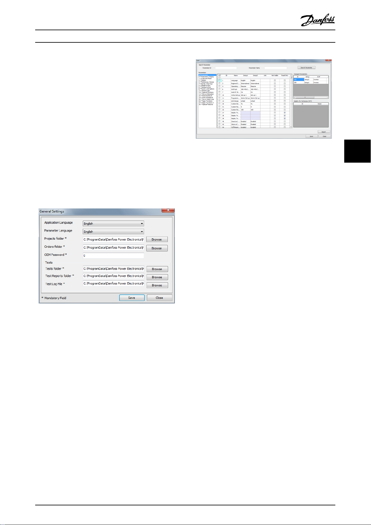
5.4 SIVP (Specific Initial Values and Protection)
5.4.1 Define the SIVP
Use the SIVP tool to define the factory default settings and attributes of parameters in each project:
Read/write
•
Read only
•
Hidden
•
.
55
Open SIVP
To open SIVP:
1.
Go to the Project View via [Projects → Open Project] or [Projects → New Project].
2. Unfold the project structure.
3. Click on the SIVP element in the project structure.
4.
The SIVP dialog opens, see Illustration 5.23.
Illustration 5.23 SIVP Dialog, Example
22 Danfoss A/S © Rev. 2014-06-09 All rights reserved. MG10X102
Page 25

Engineering Tool Functions
Operating Instructions
SIVP, left panel
The SIVP dialog displays a list of all available parameters
with their default settings.
1. Click on the parameter group name in the left
panel.
2. The parameters within the group are displayed in
the centre panel.
SIVP, right panel
The SIVP dialog displays a list of available parameters with
default settings. The status fields in the right-hand panel
show lists of:
Changed parameters
•
Parameters which are visible for technician (VFT),
•
in the Technician Tool.
To import parameter settings from other projects, click
[Import].
To save parameter settings, click [Save].
SIVP, centre panel
Set the desired status for use of each parameter in the
frequency converter, as shown in Table 5.3.
5 5
Field Set status Comment
VFT Check this box for VFT
(visible for technician)
functionality.
Set-up 1 Enter a value or select
from the drop-down
menu.
Set-up 2 Enter value or select from
the drop-down menu.
Unit Enter the unit. Where applicable, the unit
Not
visible
Read
only
Check this box to make
the parameter invisible in
the frequency converter.
Check this box to remove
write access to the
parameter in the
frequency converter.
When a parameter is
marked as VFT, the
parameter settings are
visible and can be
changed in the Technician
Tool.
The selected value
becomes the factory
setting in the frequency
converter, activated after
frequency converter reset.
-
of the parameter is
displayed.
The selected parameter is
no longer displayed in the
LCP.
In the LCP, the selected
parameter is displayed,
but the settings cannot
be changed.
Table 5.3 SIVP Centre Panel
MG10X102 Danfoss A/S © Rev. 2014-06-09 All rights reserved. 23
Page 26

Engineering Tool Functions Operating Instructions
5.4.2 SIVP Examples
55
Illustration 5.24 SIVP All Parameters
Illustration 5.25 Example: SIVP Parameter Group 2
24 Danfoss A/S © Rev. 2014-06-09 All rights reserved. MG10X102
Page 27
Engineering Tool Functions Operating Instructions
5.4.3 Copy SIVP Library
To copy the SIVP Library from one PC to another:
1. Open Windows Explorer.
2. Open the project folder.
2a To find the project folder go to [Menu
→ General Settings].
2b The project folder is displayed in the
field Projects folder, as shown in
Illustration 5.26.
2c
The default project folder is C:
\ProgramData\Danfoss Power Electronics
\MCT21 Factory Tool\Projects\.
3.
Select the required SIVP file (suffix .siv) and copy
it to a suitable media (for example, a USB stick).
4. Move the media to the destination PC.
Illustration 5.27 SIVP Dialog
5.5 Tests
A test comprises a sequence of actions, testing the
interaction of the frequency converter and the motor.
The Engineering Tool offers the following test functionalities:
Create test
•
Edit test
•
Run test
•
View test results
•
Remove test
•
1) The Run test and View test results functions are the same
for the Engineering Tool and the Technician Tool.
1)
1)
5 5
Illustration 5.26 General Settings Dialog, showing the Projects
Folder
5. On the destination PC, open the SIVP dialog as
shown in chapter 5.4.1 Define the SIVP.
6.
In the SIVP dialog (Illustration 5.27), click on
[Import], to import SIVP.
7. Click on [Save].
8. The SIVP Library is now stored on the destination
PC.
Create Test
5.5.1
To create a new test:
1. In the menu bar, go to [Tools → Common Test
Database].
2.
The Test Database dialog opens, see
Illustration 5.28.
MG10X102 Danfoss A/S © Rev. 2014-06-09 All rights reserved. 25
Page 28

Engineering Tool Functions
Operating Instructions
The following commands are available within each test
step, to activate and monitor the frequency converter:
Initialise drive
•
Read
•
Write
•
Wait
•
Write Control Word
•
For more information refer to chapter 5.5.2 Edit Test.
55
5.5.2 Edit Test
Before editing a test, it is necessary to understand:
Range of commands available, see
•
chapter 5.5.2.1 Commands.
Predefined commands, see chapter 5.5.1 Create
•
Test.
How to edit, see chapter 5.5.2.2 Editing Procedure.
•
Illustration 5.28 Test Database Dialog
Commands
Initialise drive
•
Read
•
Write
•
Wait
•
Write Control Word
•
3. Click on [Add New Test].
4.
The New Test dialog opens, see Illustration 5.29.
The new test contains several predefined initial steps by
default, see Illustration 5.29. The predefined initial steps
activate a function which monitors the communication
between the PC and the frequency converter. If communication fails, these steps ensure that the frequency
converter stops automatically. Therefore, consider possible
negative impact on the test before changing or removing
the predefined steps in the sequence.
Illustration 5.29 Create Test, Predefined Steps
5.5.2.1
The following commands are available within each test
step, to activate and monitor the frequency converter:
View the available commands via the drop down menu, as
shown in Illustration 5.30.
Write enables change of a parameter value, for example
preset references or ramp times.
Wait tells the tool to wait for a specified time or condition
before executing the next step. For example, using the
wait command, the tool can wait until a motor has
accelerated to a certain speed before performing the next
command. Note: Enter the time in ms (1000 ms = 1 s).
Read tells the tool to fetch a value from a parameter. The
test fails if a read function does not match the defined
value. For example, in Illustration 5.31, the language
selection must be English. If it is not English, the test will
be marked as failed.
Write Control Word consists of a control word and a
reference value. For details see chapter 5.5.3 Control Word
according to FC Profile (CTW).
26 Danfoss A/S © Rev. 2014-06-09 All rights reserved. MG10X102
Page 29

Engineering Tool Functions Operating Instructions
WARNING
UNINTENDED START
Depending on the settings of the frequency converter,
editing a command can start the motor. Unintended
start during programming can result in death, serious
injury, or property damage. To prevent unintended
motor start:
Disconnect the frequency converter from mains.
•
Press [Off/Reset] on the LCP before editing a
•
command.
Ensure the frequency converter, motor, and any
•
driven equipment are fully wired and
assembled when the frequency converter is
connected to AC mains, DC power supply, or
load sharing.
5.5.2.2
To edit a test:
Editing Procedure
1. Use the checkmark to select the test from the list,
see Illustration 5.32.
2. Click on [Edit].
3.
The Edit Test dialog opens, see Illustration 5.33.
5 5
Illustration 5.30 Create Test, Commands Available
Illustration 5.31 Create Test, Write Command
Illustration 5.32 Select Test for Editing
4. To view the sub-steps for each predefined
process, click on [+], as shown in Illustration 5.33.
5.
The sub-steps unfold as shown in Illustration 5.34.
Illustration 5.33 Edit Test
MG10X102 Danfoss A/S © Rev. 2014-06-09 All rights reserved. 27
Page 30

Engineering Tool Functions
55
Illustration 5.34 Example: Process Step Expanded to show Substeps
Operating Instructions
Bit Bit value=0 Bit value=1
00 Reference value External selection lsb
01 Reference value External selection msb
02 DC brake Ramp
03 Coasting No coasting
04 Quick stop Ramp
05 Hold output frequency Use ramp
06 Ramp stop Start
07 No function Reset
08 No function Jog
09 Ramp 1 Ramp 2
10 Data invalid Data valid
11 No function Relay 01 active
12 No function Relay 04 active
13 Parameter set-up Selection lsb
14 Parameter set-up Selection msb
15 No function Reverse
6. Enter a new command by defining each of the
fields Action, ID (parameter number), Name
(parameter name).
7. Click [Save].
8. Continue to enter each new command. Click
[Save] after each one.
9. When all new commands are completed, click
[Execute]. The test is saved.
10.
The dialog closes and returns to the Test Drive
and Motor dialog (shown in Illustration 5.32).
Control Word according to FC Profile
5.5.3
(CTW)
To select FC protocol in the control word, set 8-10 Control
Word Profile to [0] Frequency converter profile . The control
word is used to send commands from a master (PLC or PC)
to a follower (frequency converter).
Table 5.4 Bit Values for FC Control Word
Explanation of the control bits
Bits 00/01 Reference value
Bits 00 and 01 are used to choose between the 4 reference
values, which are pre-programmed in 3-10 Preset Reference
according to Table 5.5.
NOTICE
In 8-56 Preset Reference Select a selection is made to
define how bit 00/01 gates with the corresponding
function on the digital inputs.
Bit 01 Bit 00 Programmed
ref. value
0 0 1
0 1 2
1 0 3
1 1 4
Table 5.5 Programmed Reference Values for Bits
Bit 02, DC brake
Bit 02=0 - leads to DC braking and stop. Braking current
and duration are set in 2-01 DC Brake Current and 2-02 DC
Braking Time.
Bit 02=1 - leads to ramping.
Bit 03, Coasting
Bit 03=0 - causes the frequency converter to immediately
coast the motor to a standstill.
Bit 03=1 - enables the frequency converter to start the
motor if the other starting conditions have been fulfilled.
Parameter
[0] 3-10 Preset Reference
[1] 3-10 Preset Reference
[2] 3-10 Preset Reference
[3] 3-10 Preset Reference
28 Danfoss A/S © Rev. 2014-06-09 All rights reserved. MG10X102
Page 31

Engineering Tool Functions
Operating Instructions
NOTICE
In 8-50 Coasting Select a selection is made to define how
bit 03 gates with the corresponding function on a digital
input.
Bit 04, Quick stop
Bit 04=0 - causes a quick stop, ramping the motor speed
down to stop via 3-81 Quick Stop Ramp Time.
Bit 04=1 - the frequency converter ramps the motor speed
down to stop via 3-42 Ramp 1 Ramp Down Time or
3-52 Ramp 2 Ramp Down Time.
Bit 05, Hold output frequency
Bit 05=0 - causes the present output frequency (in Hz) to
freeze. The frozen output frequency can only be changed
with the digital inputs (5-10 Terminal 18 Digital Input to
5-15 Terminal 33 Digital Input) programmed to Speed up
and Speed down.
Bit 05=1 - use ramp.
NOTICE
If Freeze output is active, stop the frequency converter
with:
Bit 03 Coasting stop
•
Bit 02 DC braking
•
Digital input (5-10 Terminal 18 Digital Input to
•
5-15 Terminal 33 Digital Input) programmed to
DC braking, Coasting stop, or Reset and coasting
stop.
Bit 06, Ramp stop/start
Bit 06=0 - causes a stop, in which the motor speed is
ramped down to stop via the selected Ramp down
parameter.
Bit 06=1 - permits the frequency converter to start the
motor if the other starting conditions have been fulfilled.
NOTICE
In 8-53 Start Select a selection is made to define how bit
06 Ramp stop/start gates with the corresponding
function on a digital input.
Bit 09, Selection of ramp 1/2
Bit 09=0 - ramp 1 is active (3-40 Ramp 1 Type to 3-47 Ramp
1 S-ramp Ratio at Decel. Start).
Bit 09=1 - ramp 2 (3-50 Ramp 2 Type to 3-57 Ramp 2 Sramp Ratio at Decel. Start) is active.
Bit 10, Data not valid/data valid
Is used to tell the frequency converter whether it should
use or ignore the control word.
Bit 10=0 - the control word is ignored.
Bit 10=1 - the control word is used. This function is
relevant because the control word is always contained in
the telegram, regardless of which type of telegram is used.
Therefore, the control word can be turned off if it is not
required when updating or reading parameters.
Bit 11, Relay 01
Bit 11=0 - relay 01 not activated.
Bit 11=1 - relay 01 activated, provided Control word bit 11
has been chosen in 5-40 Function Relay.
Bit 12, Relay 04
Bit 12=0 - relay 04 has not been activated.
Bit 12=1 - relay 04 has been activated, provided Control
word bit 12 has been chosen in 5-40 Function Relay.
Bit 13/14, Selection of set-up
Bits 13 and 14 are used to choose from the 4 menu setups according to Table 5.6:
The function is only possible when Multi-Set-ups is selected
in 0-10 Active Set-up.
Set-up Bit 14 Bit 13
1 0 0
2 0 1
3 1 0
4 1 1
Table 5.6 Selection of Set-up
NOTICE
In 8-55 Set-up Select a selection is made to define how
bit 13/14 gates with the corresponding function on the
digital inputs.
5 5
Bit 07, Reset
Bit 07=0 - does not cause a reset.
Bit 07=1 - causes the reset of a trip. Reset is activated on
the signals leading edge, that is, when changing from logic
0 to logic 1.
Bit 08, Jog
Bit 08=0 - no function.
Bit 08=1 - 3-19 Jog Speed [RPM] determines the output
frequency.
MG10X102 Danfoss A/S © Rev. 2014-06-09 All rights reserved. 29
Bit 15 Reverse
Bit 15=0 - no reversing.
Bit 15=1 - reversing.
Page 32

Engineering Tool Functions
NOTICE
The control word cannot overrule settings in the
frequency converter. For example, when the frequency
converter is stopped via the LCP or a digital input
(coast), it will not accelerate when sending a start
command via bus.
Examples
CTW Action
047C Start motor
55
043C Stop
847C Start reversing
046C Quickstop
007C No function (bit 10=0)
Table 5.7 Examples
Definition of Reference
5.5.4
Operating Instructions
3.
The Test Drive and Motor dialog opens, see
Illustration 5.37.
4. Use the checkmark to select the test(s) from the
list.
5. Click [Run].
6. Click [Results] to view the test report.
Illustration 5.35 Definition of Reference
Illustration 5.36 Minimum and Maximum Reference
5.5.5 Select and Run Test, View Test Report
Run a single test, or several tests
To run a single test, or a group of tests:
1. Go to the project view. For more information, see
chapter 5.1.4 Open Project.
2. In the left panel click on [Test] in the project
structure.
Illustration 5.37 Test Drive and Motor Dialog
Run all tests
To run all tests:
1. Follow steps 1, 2, and 3 above.
2. In the left panel click on [Test] in the project
structure.
3. Click [Run All Tests].
4. Click [All Test Results] to view the test report.
Remove Test
5.5.6
To remove a test or tests from a project:
1. Go to the project view. For more information, see
chapter 5.1.4 Open Project.
2. In the left panel click on [Test] in the project
structure.
3.
The Test Drive and Motor dialog opens, see
Illustration 5.37.
4. Use the checkmark to select the test(s) from the
list.
5. Click on [Remove].
30 Danfoss A/S © Rev. 2014-06-09 All rights reserved. MG10X102
Page 33

Engineering Tool Functions
6. The test or tests are now removed from the
project. Confirm by checking the list of tests in
the Test Drive and Motor dialog.
Operating Instructions
5.5.7 Copy Test
1. Open Windows Explorer.
2. Open the test folder.
2a To find the test folder go to [Menu →
General Settings].
2b The test folder is displayed in the field
Tests folder, as shown in Illustration 5.38.
2c
The default test folder is C:\ProgramData
\Danfoss Power Electronics\MCT21 Factory
Tool\Projects\.
5 5
Illustration 5.38 General Settings Dialog, showing Tests Folder
3. Select the desired test file (suffix “.Test”) and copy
it to a suitable media (e.g. USB stick).
4. Move the media to the destination PC.
5. On the destination PC, copy the test to the test
folder path specified in the General Settings
dialog (see Illustration 5.38).
6. The test is now available for selection in the
Engineering Tool and the Technician Tool on the
destination PC.
MG10X102 Danfoss A/S © Rev. 2014-06-09 All rights reserved. 31
Page 34

Engineering Tool Functions Operating Instructions
5.6 Settings Menu
Drive Communication
5.6.2
5.6.1 General Settings
To access General Settings:
1.
Click Settings in the menu bar, see
Illustration 5.39.
2.
Select General Settings in the dropdown.
3.
The dialog opens, see Illustration 5.40.
To access serial fieldbus communication settings for the
frequency converter:
1.
Click Settings in the menu bar, see
Illustration 5.39.
2.
Select Drive Communication in the dropdown.
3.
The Serial Fieldbus Configuration dialog opens, see
Illustration 5.41.
55
Illustration 5.39 General Settings
Use the General Settings dialog to set up preferences for:
Language of the tool user interface (English or
•
German).
Language for displaying parameters (English,
•
German, French, Danish, Spanish, or Italian).
Folder location to store projects.
•
OEM password definition.
•
Tests:
•
Folder location to store test procedures.
-
Folder location to store test reports.
-
Folder location to store test log files.
-
Illustration 5.41 Serial Fieldbus Configuration, Communication
Settings
Procedure:
1. Enter the required settings. As a minimum, select
Port and enter Address. The other settings are
optional.
2. Click [Configure] to save the settings.
3. Click [Test Configuration] to check the settings
function correctly.
4. Click [Cancel] to delete the settings.
Illustration 5.40 General Settings Dialog
32 Danfoss A/S © Rev. 2014-06-09 All rights reserved. MG10X102
Page 35

Technician Tool Functions
Operating Instructions
6 Technician Tool Functions
6.1 Project
6.1.1 Open a Project
At the start-up of the Technician Tool, the Search dialog
opens, see Illustration 5.10. The dialog is also accessible via
[Menu → Search Project].
6 6
Illustration 6.1 Search Dialog
Use the Search dialog to find an existing project. The
existing projects originate from the Engineering Tool, see
chapter 5.1.1 Create a Project.
To search for a project, refer to the instructions in
chapter 5.1.5 Search Project.
Open a project
To open a project in the Search Result dialog:
1. Double-click on the project, or
2. Use the check box to mark the required project,
and click [Open]
3.
The Project View dialog opens.
Illustration 6.2 Project View Dialog
Alternative - Order file
MCT 21 Factory Tool monitors the order folder specified in
General Settings. When a user places an order file there, it
is flagged in the menu bar, see Illustration 6.3. The order
file specifies SIVP parameter, motor database and so on.
Illustration 6.3 Order Flag in the Menu Bar
After processing the order, the information transfers to a
project. Handle this project in the same way as any other
project, see Illustration 6.2.
Project View
6.1.2
Project View Dialog
The project opens in Project View, see Illustration 6.2. After
opening the project, the following actions are available in
the left-hand panel in the Project View dialog:
Project Info
•
Write to Drive
•
Compare
•
Test
•
MG10X102 Danfoss A/S © Rev. 2014-06-09 All rights reserved. 33
Project Review and Adjustments
6.1.3
Project Info
In the Project View dialog (Illustration 6.2) go to [MCT21 File
→ Project Info] to read project data:
Project details
•
Drive Information
•
Motor Information
•
Page 36

Technician Tool Functions Operating Instructions
SIVP parameters. Only SIVP parameters indicated
•
in the Engineering Tool as VTF (Visible to Factory
Tool) are visible in the Factory Tool dialog. The
technician can only edit these parameters. Other
parameters are not visible or editable by the
technician.
Edit the project
If required, edit the project in the Project Info dialog as
follows:
Adapt the entries in the dialog fields.
•
Click [Save] to overwrite a project with changes.
•
Click [Save as] to create a new project with
•
changes.
66
If no editing is required, click [Continue] to leave
everything unchanged. The Project View opens.
Create an Order
6.1.4
To create an order, refer to chapter 5.1.6 Create Order.
Write to Frequency Converter
6.1.5
To write data to the frequency converter, in the project
view go to [MCT21 File → Write to Drive] as shown in
Illustration 6.2.
The dialog Write SIVP and Selected Motors to Drive opens,
see Illustration 6.4. In the dialog,
View and edit communication settings
•
Select a pump table for the sensorless pump
•
function
View a summary of the project including motor
•
data, adjusted parameters
Transfer project data to the frequency converter
•
Illustration 6.4 Write SIVP and Selected Motors to Drive
34 Danfoss A/S © Rev. 2014-06-09 All rights reserved. MG10X102
Page 37

Technician Tool Functions
To transfer the project data to the frequency converter,
click [Write to Drive].
If an error arises during data transfer, click [Recover From
Boot Mode]. Possible errors are power loss and communication failure.
Operating Instructions
6.1.6 Compare
Use the Compare function to check whether data are
successfully transferred from the PC to the frequency
converter.
In the project view, go to [MCT 21 File → Compare].
6.2 Motor Database
In the Technician Tool, use the motor database to select
motors and to write to the frequency converter.
For more information, refer to chapter 5.2 Motor Database.
6.3 SIVP
6 6
Illustration 6.5 Test Drive and Motor
6.3.1 Select
In the Technician Tool, use the SIVP to select parameters
and write to the frequency converter.
For more information, refer to chapter 5.4 SIVP (Specific
Initial Values and Protection).
Write to Frequency Converter
6.3.2
To write SIVP to the frequency converter, refer to the
instructions in chapter 6.1.5 Write to Frequency Converter.
6.4
Tests
6.4.1 Test and Documentation
Test
To verify that a frequency converter is operating correctly,
run a defined test. The result is documented.
To run a test or tests:
1.
Open Project View.
2. Go to [MCT21 File → Test].
3.
The Test Drive and Motor dialog opens, see
Illustration 6.5.
4. Follow the steps in the following sections to run
a test or tests.
Test Information field
In the section Test Information, use the fields Tester Name
and Comment to document details about the test. For
example, enter the code number in the Comment field.
Run Test
To start a dedicated test:
Use the check boxes under the heading Select, to
•
select the test or tests.
Click [Run].
•
The selected test(s) runs.
•
To run all available tests:
Click [Run all Tests].
•
The tests run.
•
Documentation - test result
The test result is saved in a pdf file.
Name the PDF file in the format Type code + drive serial
number + date.
Documentation - test log
The output of the test is the test log, in csv file format.
The following test details are stored in the test log:
Date
•
Time
•
Order number
•
Customer name
•
Name tester
•
Drive type (15–46)
•
Serial number (15–51)
•
MG10X102 Danfoss A/S © Rev. 2014-06-09 All rights reserved. 35
Page 38

Technician Tool Functions Operating Instructions
.Siv file name
•
Comment
•
Result (pass or not passed)
•
Test report path (path with .PDF file name where
•
report was created)
66
36 Danfoss A/S © Rev. 2014-06-09 All rights reserved. MG10X102
Page 39

Index Operating Instructions
Index
C
Communication
Serial fieldbus................................................................................ 6, 32
Set-up..................................................................................................... 6
Create project........................................................................................ 10
D
De-installation.......................................................................................... 6
Dialog
General settings........................................................................... 6, 32
New project................................................................................... 6, 10
Project info.................................................................................. 11, 34
Read from drive................................................................................ 12
Search................................................................................................... 10
Test drive and motor...................................................................... 11
Write SIVP and selected motors to drive................................. 34
Discharge time......................................................................................... 4
Document version.................................................................................. 3
E
Engineering tool................................................................................. 7, 8
F
FC profile
Control bits......................................................................................... 28
Control word...................................................................................... 28
Example............................................................................................... 30
G
General settings.................................................................................... 32
H
High altitude............................................................................................. 5
High voltage............................................................................................. 4
Motor
Add to database............................................................................... 18
Common motor library.................................................................. 19
Copy library........................................................................................ 21
Database...................................................................................... 17, 35
Library management...................................................................... 19
Remove from database.................................................................. 18
Write to drive..................................................................................... 34
O
Order......................................................................................................... 13
Order file
Example............................................................................................... 15
Flag........................................................................................................ 33
Order folder........................................................................................ 33
Structure.............................................................................................. 15
P
Password
Frequency converter......................................................................... 6
OEM......................................................................................................... 6
PELV............................................................................................................. 5
Project
Copy all data...................................................................................... 15
Edit........................................................................................................ 34
Existing................................................................................................ 12
Folder................................................................................................... 15
Info........................................................................................................ 33
New....................................................................................................... 10
New, create from database.......................................................... 10
New, read from drive...................................................................... 12
Open.............................................................................................. 12, 33
Search............................................................................................ 13, 33
Search with filter.............................................................................. 13
Upgrade to new firmware............................................................. 16
View...................................................................................................... 13
Write to drive..................................................................................... 34
Project structure................................................................................... 13
Project view............................................................................................ 13
Purpose of the manual.......................................................................... 3
I
Installation................................................................................................. 6
Intended use............................................................................................. 3
Q
Qualified personnel................................................................................ 4
R
L
Leakage current....................................................................................... 5
Links............................................................................................................. 3
M
MCT 10...................................................................................................... 10
MG10X102 Danfoss A/S © Rev. 2014-06-09 All rights reserved. 37
Reference................................................................................................. 30
Removal...................................................................................................... 6
Residual Current Device....................................................................... 5
S
Set-up.......................................................................................................... 6
Page 40

Index Operating Instructions
SIVP
Definition............................................................................................ 22
Example............................................................................................... 24
In Technician Tool............................................................................ 35
Library.................................................................................................. 25
Software version...................................................................................... 3
Specific initial values and protection............................................ 22
System requirements............................................................................ 3
T
Technician tool............................................................................. 7, 9, 33
Test
Copy...................................................................................................... 31
Create................................................................................................... 25
Documentation................................................................................ 35
Edit........................................................................................................ 26
Log......................................................................................................... 35
Remove................................................................................................ 31
Report............................................................................................ 30, 35
Run................................................................................................. 30, 35
Select.................................................................................................... 30
U
Unintended motor rotation................................................................ 5
Unintended start.............................................................................. 4, 27
W
Windmilling............................................................................................... 5
Workflow........................................................................................... 7, 8, 9
38 Danfoss A/S © Rev. 2014-06-09 All rights reserved. MG10X102
Page 41

Index Operating Instructions
MG10X102 Danfoss A/S © Rev. 2014-06-09 All rights reserved. 39
Page 42

www.danfoss.com/drives
Danfoss can accept no responsibility for possible errors in catalogues, brochures and other printed material. Danfoss reserves the right to alter its products without notice. This also applies to
products already on order provided that such alterations can be made without subsequential changes being necessary in specifications already agreed. All trademarks in this material are property
of the respective companies. Danfoss and the Danfoss logotype are trademarks of Danfoss A/S. All rights reserved.
Danfoss A/S
Ulsnaes 1
DK-6300 Graasten
www.danfoss.com/drives
130R0549 MG10X102 Rev. 2014-06-09
*MG10X102*
 Loading...