

Page 1

Operating Guide
VLT® Motion Control Tool MCT 10
vlt-drives.danfoss.com
Page 2

Page 3

VLT® Motion Control Tool MCT 10
Operating Guide
Contents
1
Introduction 10
1.1
Purpose of this Operating Guide 10
Manual and Software Version 10
1.2
Intended Use 10
1.3
1.4
System Requirements 11
1.5
Software Modules 11
1.5.1
Features of the VLT® Motion Control Tool MCT 10 11
1.6
Versions 12
1.7
Further Information 13
Safety 14
2
Safety Symbols 14
2.1
Safety Precautions 14
2.2
Contents
Installation and De-installation 16
3
Introduction 16
3.1
3.1.1
Starting the Installation Program 16
3.1.2
Selecting the Software Language 16
3.1.3
Uninstalling the Software 16
4
Set-up of Communication 17
4.1
Communication Options 17
4.2
Manual Fieldbus Configuration 17
4.3
Automatic Scan 18
4.3.1
Scan Range Configuration 18
4.3.2
Scan Network 19
4.4
Set Up the Drive with RS485 Data Communication 19
4.4.1
Configuring the Fieldbus 19
4.4.2
USB Data Communication 20
4.5
Set-up of Soft Starter 20
4.5.1
Serial Configuration 21
4.5.2
Importing/Exporting Parameter Files, MCD 600 22
4.6
PROFIBUS DP-V1 Communication 24
4.6.1
Configuring PROFIBUS DP-V1 24
4.6.2
DP-V1 Connection and PG/PC Interface 25
4.6.3
PROFIBUS Multitelegrams 28
4.7
Ethernet-TSC Data Communication 28
4.7.1
Ethernet-TSC Configuration 28
AQ283728700891en-000201/130R0466 | 3Danfoss A/S © 2021.09
Page 4

VLT® Motion Control Tool MCT 10
Operating Guide
4.7.2
Wink Drive 32
4.7.3
Advanced 33
5
Parameter Set-up 35
5.1
Introduction 35
5.2
User Interface 35
5.2.1
Display 35
5.2.2
Network and Project Folders 36
5.2.3
Other Folders 37
5.3
Setting Up Drives and Folders 38
5.3.1
Inserting a New Folder 38
5.3.2
Setting Up Drives, Active Filters, or Soft Starters 38
5.3.3
Setting Up Low Harmonic Drives 39
5.3.4
All Parameters Folders 40
5.3.5
Array Parameters 41
Contents
5.3.6
Sorting 42
5.4
Customized Views 42
5.4.1
Customize Parameter View Settings 43
5.4.2
Customize Background Color 43
5.4.3
Customize Parameter View 44
5.4.4
Filtering Parameters 45
5.4.5
Customize Columns 45
5.5
Parameter Edit 46
5.6
Comparison of Parameters 48
5.7
Compare Multiple Drives 49
5.8
View Change Log 51
5.9
Read Drive Operation Status 53
6
Operation 54
6.1
Reading and Writing Parameters 54
6.1.1
Read From Drive Settings 54
6.1.2
Write to Drive Settings 55
6.1.3
Communication Fault Tolerance 55
6.2
Connection Properties 56
6.3
Read from Drive 56
6.3.1
Changing the PROFINET Host Name 58
6.4
Write to Drive 59
6.5
Write to Multiple Drives 60
6.6
Poll 62
AQ283728700891en-000201/130R04664 | Danfoss A/S © 2021.09
Page 5

VLT® Motion Control Tool MCT 10
Operating Guide
6.6.1
6.6.2
6.6.3
6.7
Changing the Set-up of a Field Device 64
6.8
Save Changes to a Hard Disk 64
6.8.1
6.8.2
6.9
Import of Older Dialog Files 65
6.10
Printing 66
6.11
Update Database Information 67
6.12
Update Drives Firmware Support in MCT 10 Set-up Software 69
6.13
Software Compatibility 70
6.13.1
6.14
Conversion Wizard 71
Contents
Stop Polling 62
Resume Polling 63
Using Smart Polling (Intelligent Scan Frequency) 63
Recoding Online Changes 64
Archive/Unarchive 65
Mapping to Compatible Firmware 70
6.14.1
Conversion 71
6.14.2
VLT to FC Series Converter Function 71
6.14.3
FC to FC Conversion 73
6.14.4
Conversion Tables Manager 73
7
Diagnostics 80
7.1
Alarm, Warning, and Fault Log Readout 80
7.2
Localization of Alarms and Warnings 80
7.3
Storing Alarms/Warnings in Project Files 81
7.4
Handling the Alarms and Warnings Loggings 81
7.5
The Scope Function 81
7.5.1
Activating the Scope - MCT 10 Set-up Software 82
7.5.2
Configuring the PC Polling Channel 83
7.5.3
PC Polling Channel Properties 85
7.5.4
Reuse of PC Polling Channel Settings 87
7.5.5
Configuring the Drive Real-time Channel 88
7.5.6
Using Advanced Triggers 90
7.5.7
Drive Real-time Channel Properties 92
7.5.8
Communication Control 93
7.5.9
Additional Functionality 93
7.5.10
Scope Storage 94
7.6
Export Log Files 95
8
Plug-ins 97
8.1
Smart Logic Controller Plug-in 97
AQ283728700891en-000201/130R0466 | 5Danfoss A/S © 2021.09
Page 6

VLT® Motion Control Tool MCT 10
Operating Guide
8.2
Time-based Actions and Preventive Maintenance Plug-ins 97
8.2.1
8.2.2
8.2.3
8.3
Motor Plug-in 100
8.3.1
8.3.2
8.3.3
8.3.4
8.4
Multi-motor Plug-in 105
8.4.1
8.4.2
8.4.3
8.4.4
Contents
Clock Functions 97
Preventive Maintenance 98
Timed Actions 99
Asynchronous Motors 102
PM Non-salient SPM 102
PM Salient IPM 103
SynRM 105
Defining Normal Operation Curve 106
Threshold 106
Coefficients 107
Modified Curves 107
8.5
Cascade Controller Plug-in 107
8.5.1
The Preconditions Tab 108
8.5.2
The Set-up Tab 111
8.5.3
The System Optimizing Tab 116
8.5.4
The Service Tab 117
8.5.5
Extended Cascade Controller Options 120
8.6
Drive File Manager Plug-in 125
8.6.1
Customer-specific Initialization Values - CSIV 125
8.6.2
Creating New CSIV Files 126
8.6.3
Configuration of CSIV Files 127
8.6.4
Drive File Manager 129
8.7
Functional Safety Configuration Plug-in 131
8.7.1
Introduction 131
8.7.2
Access 132
8.7.3
Safe Plug-in Interface 133
8.7.4
Configuration 147
8.7.5
Commissioning 152
8.7.6
Operation 154
8.8
Status Plug-in 156
8.9
Drive Control Plug-in 158
8.9.1
Launching the Drive Control Plug-in 160
8.9.2
Setting the Control Word 161
8.9.3
Start Drive Control 162
8.9.4
Changing Control Word Bits 165
AQ283728700891en-000201/130R04666 | Danfoss A/S © 2021.09
Page 7

VLT® Motion Control Tool MCT 10
Operating Guide
8.9.5
8.9.6
8.10
Decoder Plug-in 167
8.10.1
8.11
Condition-based Monitoring (CBM) Plug-in 168
8.11.1
8.11.2
8.11.3
8.11.4
8.11.5
8.11.6
Contents
Changing the Reference 166
Open Drive Control Plug-in 166
Starting the Decoder Plug-in 167
Home Page 171
Speed Range Page 172
Speed Steps Configuration Page 175
8.11.3.1
8.11.3.2
8.11.3.3
Sensor Configuration Page 179
Auto-configuration Setup Page 184
Baseline Progress Page 185
Baseline Run 175
Online Baseline 176
All Baseline Types 177
8.11.6.1
8.11.6.2
8.11.6.3
8.11.7
Thresholds Page 188
8.11.7.1
8.11.7.2
8.11.7.3
8.11.7.4
8.11.8
Monitoring Page 205
8.12
Service Log 213
9
Support of VLT® Wireless Communication Panel LCP 103 214
9.1
Introduction 214
9.1.1
Using LCP 103 with MCT 10 Set-up Software Basic Version 214
9.1.2
Using LCP 103 with MCT 10 Set-up Software Advanced Version 214
10
VLT® Software Customizer 216
Baseline Run 185
Online Baseline 186
All Baseline Types 187
Thresholds Generation 198
Numeric Parameters Editing 202
Choice List Parameters Editing 203
Thresholds Page when Auto-configuration is Selected 204
10.1
Introduction 216
10.1.1
Activation Key 217
10.1.2
Disclaimer 218
10.2
SplashScreen 219
10.2.1
Creating New from Blank 219
10.2.2
Selecting from Library 220
10.2.3
Import 220
10.3
LanguageChanger 223
AQ283728700891en-000201/130R0466 | 7Danfoss A/S © 2021.09
Page 8

VLT® Motion Control Tool MCT 10
Operating Guide
10.3.1
10.3.2
10.3.3
10.3.4
10.3.5
10.4
InitialValues 229
10.4.1
10.4.2
10.4.3
10.4.4
10.5
SmartStart 233
10.5.1
10.5.2
10.5.3
Contents
New from Blank 224
Search Filter 227
Advanced Settings 228
Audit 229
Markings 229
Creating New from Blank 230
Removing Parameters 232
Saving the CSIV File 232
Validation of Parameters During Import 233
Creating New from Blank 235
Create Diagram 239
Create Parameter Screen 240
10.5.4
Link Screens 243
10.5.5
Branching 246
10.5.6
Junction 248
10.6
Writing to Drive 248
10.6.1
Preserve Original vs. Wipe Original 249
10.7
Testing in Simulator 250
10.7.1
Installing the Simulator 251
11
Tool Calling Interface (TCI) 253
11.1
Introduction 253
11.2
Installing the GSD/GSDML File 253
11.3
Creating a Project in TIA 253
11.4
Use Cases 254
11.4.1
Doing the Initial Connection 254
11.4.2
Configuring the TCI 255
12
SyncPos 257
12.1
SyncPos Handling 257
12.2
Programs and Configuration File 257
12.2.1
Programs 257
12.2.2
Viewing the Configuration File 257
12.2.3
Importing and Exporting a Configuration File 257
12.2.4
Editing and Saving a Configuration File 258
12.2.5
Importing Program Files 259
12.2.6
Setting a Program to Auto Start 260
AQ283728700891en-000201/130R04668 | Danfoss A/S © 2021.09
Page 9

VLT® Motion Control Tool MCT 10
Operating Guide
12.2.7
Editing Source Code 261
12.2.8
Saving and Exiting Program 261
12.3
SyncPos Read From Drive 262
12.4
SyncPos Write to Drive 263
13
Troubleshooting 265
13.1
Save Error Dialog 265
13.2
Common Problems and Solutions 266
13.2.1
Changes are not Saved to PC 266
13.2.2
Error Message While Installing MCT 10 Set-up Software 266
13.2.3
Error Message Communication Failed 266
13.2.4
Communication Errors 267
13.2.5
Help 268
13.3
Safe Plug-in 268
13.3.1
Troubleshooting Communication Errors 268
Contents
13.3.2
Troubleshooting CRC Errors 268
13.3.3
Warnings and Alarms 269
AQ283728700891en-000201/130R0466 | 9Danfoss A/S © 2021.09
Page 10

Edition
Remarks
Software version
AQ283728700891, version 0201
Upgrade to new software version. Support of Multiple Drive Handling, Wireless Direct, and Condition-based Monitoring.
5.3
VLT® Motion Control Tool MCT 10
Operating Guide
Introduction
1 Introduction
1.1 Purpose of this Operating Guide
This manual provides basic knowledge required to use the MCT 10 Set-up Software with Danfoss drives. Familiarity with the following is assumed:
•
MS®-Windows™ at user level.
•
Set-up, process knowledge, and operation of drive.
•
Use of and linkage with communication equipment.
The manual does not provide any detailed information regarding specific applications or possible solutions and related parameter
combinations in the set-up and use of a drive. Refer to the operating guide and design guide of the drive. Any update of the manual
and instructions related to the MCT 10 Set-up Software is available at www.danfoss.com.
Familiarity with the PC or PLC master of the system is assumed. Issues regarding hardware or software produced by other manufacturers are beyond the scope of this manual and are not the responsibility of Danfoss.
Refer to the appropriate manuals for more information about master-to-master communication, or communication to a non-Danfoss slave.
1.2 Manual and Software Version
This manual is regularly reviewed and updated. All suggestions for improvement are welcome.
The original language of this manual is English.
1.3 Intended Use
The MCT 10 Set-up Software enables full system configuration and control. With MCT 10, it is possible to monitor the entire system
more efficiently for faster diagnosis and better preventive maintenance.
MCT 10 is designed as an interactive commissioning tool for quick and easy commissioning of the following drive series:
•
VLT® 2800.
•
VLT® 4000.
•
VLT® 5000.
•
VLT® 6000.
•
VLT® 8000.
•
VLT® Micro Drive FC 51.
•
VLT® HVAC Basic Drive FC 101.
•
VLT® HVAC Drive FC 102.
•
VLT® Refrigeration Drive FC 103.
•
VLT® AQUA Drive FC 202.
•
VLT® Midi Drive FC 280.
•
VLT® AutomationDrive FC 301/FC 302.
•
VLT® AutomationDrive FC 360.
•
VLT® Decentral Drive FCD 302.
•
VLT® DriveMotor FCM Series.
•
VLT® Compressor Drive CD 302.
•
VLT® Compressor Drive CDS 302.
•
VLT® Compressor Drive CDS 303.
•
VLT® Soft Starter MCD 500.
•
VLT® Soft Starter MCD 600.
AQ283728700891en-000201 / 130R046610 | Danfoss A/S © 2021.09
Page 11

VLT® Motion Control Tool MCT 10
Operating Guide
•
VLT® Advanced Active Filter AAF 005.
•
VLT® Advanced Active Filter AAF 006.
Use cases of the MCT 10:
•
For planning a new communication network offline. The MCT 10 contains a complete database with all Danfoss Drives products.
•
For commissioning drives online.
•
For easy replacement of drives.
•
For easy expansion of networks with more drives.
•
For back-up of parameter settings of drives in a communication network.
•
The MCT 10 supports PROFIBUS DP-V1 communication via a master class 2 connection. This connection eliminates the need for
an extra communication network.
The communication framework part of MCT 10 is handling the control of the fieldbuses. It provides enhanced capabilities allowing
multiple concurrent fieldbus communication. Several fieldbuses can be configured and combined in the same network within MCT
10.
Introduction
N O T I C E
If several fieldbuses are created with the same type, make sure that they are configured with different scan ranges.
1.4 System Requirements
To use the VLT® Motion Control Tool MCT 10, the IBM-compatible computer must meet the following minimum system requirements:
4 GB of available space on the hard drive.
•
MCT 10 runs on Windows™ 10 32/64-bit editions.
1.5 Software Modules
The VLT® Motion Control Tool MCT 10 Set-up Software is supplied in 2 modules:
•
MCT 10 Set-up Software for:
-
Setting the drive parameters.
-
Copying parameter sets to and from a drive.
-
Documentation/printout of set-up, including diagrams.
-
Servicing and fault analysis.
•
APoss program for creating APoss programs.
1.5.1 Features of the VLT® Motion Control Tool MCT 10
•
Project-oriented PC tool, 1 tool for all drive series.
•
Links to all Windows applications possible.
•
Supports Siemens CP PCMCIA-and PCI cards for PROFIBUS DP-V1 master class 2 connection.
•
Supports standard interfaces: COMx, USB, RS232 (Flux).
•
Siemens PG/Field PGs already have the required hardware.
•
View is highly individually configurable.
•
Downwards compatibility with Dos-Dialog (*.mnu) and WinDialog (*.vlt).
•
Windows™ Explorer-like interface for quick and easy start-up and navigation.
•
Wireless Direct.
AQ283728700891en-000201 / 130R0466 | 11Danfoss A/S © 2021.09
Page 12

e30bt513.12
PC (Master)
USB to RS485 converter
#1
#2
#3 #126
Version supports
MCT 10 Set-up Software
Advanced
MCT 10 Set-up Software Basic
Drives per project
Unlimited
4
FC protocol
✓
✓
Functional safety
✓
✗
USB
✓
✓
PROFIBUS DP-V1
✓
✓
PROFIBUS DP-V1 handling multiple Danfoss nodes concurrently
✓ (limited performance)
✗
Ethernet-TSC
✓
✓
Logging and scope function
8 channels
2 channels
Real-time logging from a drive
4 channels
✗
Alarm display
✓
View only
VLT® Motion Control Option MCO 305
✓
✓
Graphical smart logic control
✓
✓
VLT® 5000 to FC 302, VLT® 6000 to FC 102, and VLT® 2800 to FC 280 conversion wizards
✓
✓
VLT® Motion Control Tool MCT 10
Operating Guide
Introduction
Illustration 1: Connect up to 126 Nodes with a Repeater and up to 31 Nodes without Repeater
1.6 Versions
VLT® Motion Control Tool MCT 10 is available in 2 versions:
•
MCT 10 Set-up Software Basic is available free of charge. Download the program from www.danfoss.com - select VLT® Motion
Control Tool MCT 10.
•
MCT 10 Set-up Software Advanced can be purchased using ordering number 130B1000.
Table 1: Features of the Basic and Advanced Versions
AQ283728700891en-000201 / 130R046612 | Danfoss A/S © 2021.09
Page 13

Version supports
MCT 10 Set-up Software
Advanced
MCT 10 Set-up Software Basic
FC to FC conversion wizard
✓
✓
Import 3000.XLS to FC 302
✓
✗
Motor database
✓
✗
VLT® Extended Cascade Controller MCO 101
✓
✗
Drive file system
✓
✗
VLT® Wireless Control Panel LCP 103
✓
✓
Status plug-in
✓
✓
Drive plug-in
✓
✗
VLT® Software Customizer
✓
✗
VLT® Motion Control Tool MCT 10
Operating Guide
1.7 Further Information
The following manuals related to VLT® Motion Control Tool MCT 10 are available:
•
VLT® PROFIBUS DP-V1 MCA 101 Installation Guide.
•
Design guides for the relevant drives.
Refer to www.danfoss.com/en/about-danfoss/our-businesses/drives/ for more information.
It is also possible to find video training material on this site for operating the MCT 10.
Introduction
AQ283728700891en-000201 / 130R0466 | 13Danfoss A/S © 2021.09
Page 14

VLT® Motion Control Tool MCT 10
Operating Guide
2 Safety
2.1 Safety Symbols
The following symbols are used in this manual:
D A N G E R
Indicates a hazardous situation which, if not avoided, will result in death or serious injury.
W A R N I N G
Indicates a hazardous situation which, if not avoided, could result in death or serious injury.
C A U T I O N
Indicates a hazardous situation which, if not avoided, could result in minor or moderate injury.
N O T I C E
Indicates information considered important, but not hazard-related (for example messages relating to property damage).
Safety
2.2 Safety Precautions
W A R N I N G
HIGH VOLTAGE
AC drives contain high voltage when connected to AC mains input , DC supply , or load sharing. Failure to perform installation,
start-up, and maintenance by qualified personnel can result in death or serious injury.
Only qualified personnel must perform installation, start-up, and maintenance.
-
W A R N I N G
UNINTENDED START
When the drive is connected to the AC mains, DC supply, or load sharing, the motor may start at any time, causing risk of death,
serious injury, and equipment, or property damage. The motor may start by activation of an external switch, a fieldbus command,
an input reference signal from the LCP or LOP, via remote operation using MCT 10 Set-up software, or after a cleared fault condi-
tion.
Press [Off] on the LCP before programming parameters.
-
Disconnect the drive from the mains whenever personal safety considerations make it necessary to avoid unintended motor
-
start.
Check that the drive, motor, and any driven equipment is in operational readiness.
-
AQ283728700891en-000201 / 130R046614 | Danfoss A/S © 2021.09
Page 15

VLT® Motion Control Tool MCT 10
Operating Guide
Safety
W A R N I N G
DISCHARGE TIME
The drive contains DC-link capacitors, which can remain charged even when the drive is not powered. High voltage can be
present even when the warning indicator lights are off.
Failure to wait the specified time after power has been removed before performing service or repair work could result in death or
serious injury.
Stop the motor.
-
Disconnect AC mains, permanent magnet type motors, and remote DC-link supplies, including battery back-ups, UPS, and
-
DC-link connections to other drives.
Wait for the capacitors to discharge fully before performing any service or repair work. The discharge time is specified in the
-
drive operating guides.
Use a measuring device to make sure that there is no voltage, before opening the drive or performing any work on the ca-
-
bles.
AQ283728700891en-000201 / 130R0466 | 15Danfoss A/S © 2021.09
Page 16

e30bt514.14
VLT® Motion Control Tool MCT 10
Operating Guide
Installation and De-installation
3 Installation and De-installation
3.1 Introduction
The VLT® Motion Control Tool MCT 10 Software and SyncPos modules are installed via a multilingual, self-explanatory installation
program.
3.1.1 Starting the Installation Program
Procedure
1.
Run VLT_MCT10_Vx.xx.msi.
2.
Follow the instructions of the installation program.
When the installation process is complete, the MCT 10 Set-up Software can be found on the following path:
Illustration 2: Path for MCT 10 Set-up Software
3.1.2 Selecting the Software Language
The Danfoss default language is English. If another language is selected, it becomes the new default.
Procedure
1.
Select Options from the main menu, then select Select Language.
2.
Select the wanted language from the scrollbar and click OK.
N O T I C E
Changing the language affects the parameter language. If an external LCP is connected to the drive, the change of lan-
guage version does not affect the language in the display.
3.
Close and restart MCT 10 to activate the language setting.
3.1.3 Uninstalling the Software
N O T I C E
The following procedure is only valid for Windows operating systems.
Procedure
1.
Select Start.
2.
Select Settings.
3.
Select Control Panel.
4.
Double-click Remove/Add Programs.
5.
Select Remove.
AQ283728700891en-000201 / 130R046616 | Danfoss A/S © 2021.09
Page 17

e30bt631.11
VLT® Motion Control Tool MCT 10
Operating Guide
Set-up of Communication
4 Set-up of Communication
4.1 Communication Options
Drives in the VLT® HVAC Drive FC 102, VLT® AQUA Drive FC 202, and VLT® AutomationDrive FC 302 series are equipped with a USB
port. Communication from a PC can be established using a standard A–B male-to-male USB cable connected to the drive. No extra
hardware or bus configuration is required. If the PC is equipped with more than 1 USB port, several drives can be connected. The
USB bus is automatically added to the network bus list.
Establish a hardwired connection through:
•
Standard built-in RS485, or
•
USB port.
The USB interface socket allows devices to be connected and disconnected using hot swapping. When connecting a drive using
USB, MCT 10 Set-up Software automatically adds on to the bus list.
If the VLT® PROFIBUS DP-V1 MCA 101 or the VLT® EtherNet/IP MCA 121 option is mounted in the drive, establish the connection
through:
•
PROFIBUS master class 2 connection (MSAC 2), or
•
Ethernet-based network.
N O T I C E
Connect soft starters either via a USB cable or via ethernet.
N O T I C E
RISK OF DAMAGE TO PC USB HOST CONTROLLER
When connecting the PC to the drive through the USB cable, there is a risk of damaging the PC USB host controller.
Follow the recommendations for grounding described in the Operating Guide for the relevant drive.
-
Use a USB isolator with galvanic isolation to protect the PC USB host controller from ground potential differences when con-
-
necting the PC to a drive through a USB cable.
Do NOT use a PC power cable with a ground plug when the PC is connected to the drive through a USB cable.
-
Communication from a PC can be established via RS232 to RS485 converters or via USB to RS485 converters.
Illustration 3: Communication from a PC
4.2 Manual Fieldbus Configuration
After installation, configure the non-plug-and-play networks via the fieldbus configuration dialog.
Procedure
1.
Start the MCT 10 Set-up Software.
2.
Select Network.
AQ283728700891en-000201 / 130R0466 | 17Danfoss A/S © 2021.09
Page 18

e30bt622.12
e30bt630.13
VLT® Motion Control Tool MCT 10
Operating Guide
3.
Right-click Network and select Add/Remove/Configure Buses.
Illustration 4: Refreshing the Fieldbus List
4.
Add, remove, or configure the properties for the connected buses.
Set-up of Communication
Illustration 5: Fieldbus Configuration
5.
Scan the network for active drives to make MCT 10 indicate available drives on the non-plug-and-play fieldbuses.
4.3 Automatic Scan
Only the USB fieldbus is scanned automatically when a drive is connected to the PC. For non-plug-and-play fieldbuses, scan manually for active drives.
4.3.1 Scan Range Configuration
Enter the preferred scan setting by right-clicking SerialCom and then selecting Configure Driver.
Adding a standard bus RS485 or PROFIBUS to the network tree configures the scan range to scan the entire address range. The
Ethernet-TSC bus is added using the current IP address settings.
The fieldbus scan range can be configured in several ways:
•
Right-click the Fieldbus icon in the network tree and select Configure Bus.
•
Mark the Fieldbus icon in the network tree and select Configure under Communication in the main menu bar.
•
Open the Fieldbus Configuration dialog, right-click the Network icon, and select Add/Remove/Configure Buses.
Open from the Windows panel.
•
AQ283728700891en-000201 / 130R046618 | Danfoss A/S © 2021.09
Page 19

e30bt495.14
Scan network icon
e30bt496.12
VLT® Motion Control Tool MCT 10
Operating Guide
Illustration 6: Scan Network Icon
Set-up of Communication
4.3.2 Scan Network
Scan a fieldbus in 3 ways:
•
Right-click the Fieldbus icon in the network tree and select Scan Bus for active drives.
•
Mark the Fieldbus icon in the network tree and select Scan/Refresh under Communication in the main menu bar.
•
Mark the Fieldbus icon in the network tree and select the Scan icon on the toolbar.
The Scanning for Drives window appears and indicates the progress of the scan.
Illustration 7: Progress of Network Scanning
4.4 Set Up the Drive with RS485 Data Communication
All drives can be configured to 300, 1200, 4800, 9600 (default), 19200, 38400, 57600, or 115200 baud. The serial configuration is
always configured with:
•
8 data bits.
•
1 stop bit.
•
Even parity.
4.4.1 Configuring the Fieldbus
When using an RS485 converter as the Advantech ADAM converter, MCT 10 Set-up Software indicates online drives available on the
fieldbus after scanning the bus.
N O T I C E
Protocol and advanced settings are for performance optimization and should normally not be changed.
Procedure
AQ283728700891en-000201 / 130R0466 | 19Danfoss A/S © 2021.09
Page 20

e30bt629.12
e30bt623.12
VLT® Motion Control Tool MCT 10
Operating Guide
1.
Open the Serial Fieldbus Configuration dialog box or right-click the appropriate fieldbus.
Illustration 8: Serial Fieldbus Configuration
2.
Set the COM port number.
Set-up of Communication
When using USB to RS485 converters, the actual COM port number can be identified from the device manager part of the
Windows control panel.
3.
Set the baud rate, parity, and the number of stop bits (must match the settings in the drive).
4.
Set the fieldbus scanning range to the available address to limit the time scanning for active drives.
5.
Press OK to activate settings or select to restore the default settings.
4.4.2 USB Data Communication
Illustration 9: Network Bus List
When the USB cable is disconnected, the drive connected via the USB port is removed from the network bus list.
4.5 Set-up of Soft Starter
Setting up connectivity to the VLT® Soft Starter MCD 500 and VLT® Soft Starter MCD 600 requires that the USB communication module is mounted on the soft starter. Communication from a PC can be established using a standard A–B male-to-male USB cable
connected to the USB communication module. If the PC is equipped with more than 1 USB port or a USB HUB, several soft starters
can be connected.
AQ283728700891en-000201 / 130R046620 | Danfoss A/S © 2021.09
Page 21

e30bt758.12
VLT® Motion Control Tool MCT 10
Operating Guide
Set-up of Communication
4.5.1 Serial Configuration
All soft starters can be configured to 300, 1200, 4800, 9600 (default), 19200, 38400, 57600, or 115200 baud. The serial configuration
is always configured with:
•
8 data bits.
•
1 stop bit.
•
No parity.
Illustration 10: Serial Configuration of Soft Starters
4.5.1.1 Configuring the Fieldbus
Procedure
1.
Add and configure the bus from the Fieldbus Configuration dialog.
If the bus is already added to the network, it can be reconfigured by right-clicking on the appropriate soft starter fieldbus.
2.
Set the COM port number. The actual COM port number can be identified from the device manager part of the control
panel.
3.
Set the baud rate, parity, and the number of stop bits (must match the setting in the soft starter).
4.
Reset to Default restores the general settings and fieldbus scanning to factory configuration values.
4.5.1.2 Using the Hilscher NetIdent Protocol
Use the tool for searching for devices and for identifying and changing IP addresses. The tool also has a filtering function.
Procedure
1.
Click the Tools menu.
AQ283728700891en-000201 / 130R0466 | 21Danfoss A/S © 2021.09
Page 22

e30bt980.12
VLT® Motion Control Tool MCT 10
Operating Guide
2.
Select Soft Starter Discover and Configuration Tool.
Set-up of Communication
Illustration 11: Selecting the Hilscher NetIdent Tool
3.
Select the soft starter for which the IP address should be configured.
4.
Click Configure.
4.5.2 Importing/Exporting Parameter Files, MCD 600
With VLT® Soft Starter MCD 600, a parameter file (PAR file) can be exported from the soft starter to a USB stick and copied into VLT®
Motion Control Tool MCT 10. After changing the file in MCT 10, the PAR file can be copied back to the USB stick and applied to the
soft starter.
Procedure
Create an MCD 600 project soft starter.
1.
Right-click the project folder.
2.
3.
Select Import parameters.
From the dialog, select the file to import.
4.
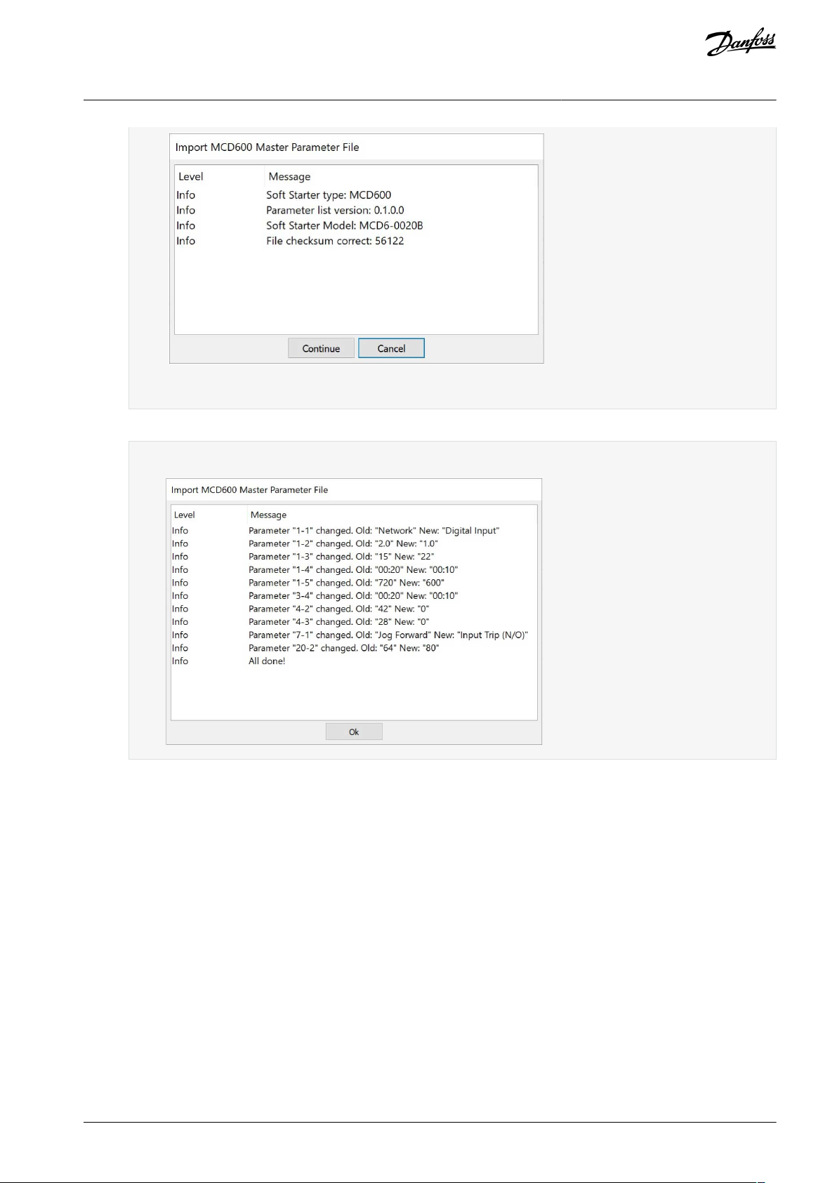
A dialog opens showing information about the selected file.
AQ283728700891en-000201 / 130R046622 | Danfoss A/S © 2021.09
Page 23
e30bu310.12
e30bu311.12
VLT® Motion Control Tool MCT 10
Operating Guide
If the soft starter differs from the project, it shows up as an error or warning in this view, depending on the difference.
5.
Press Continue to apply the file.
A view, which shows all changed parameters, appears.
Set-up of Communication
6.
Click Ok to close the window.
7.
Right-click the project to export from MCT 10.
8.
Select the parameters to export.
9.
In the file selection dialog, select where to export the file to.
A dialog appears when the export is completed.
AQ283728700891en-000201 / 130R0466 | 23Danfoss A/S © 2021.09
Page 24

e30bu312.11
e30bt634.11
PCMCIA
DP-V1 card
DP-V1
#1
#2 #N
DP-V1
#1
#2 #N
Insertable
DP-V1 card
VLT® Motion Control Tool MCT 10
Operating Guide
Set-up of Communication
4.6 PROFIBUS DP-V1 Communication
Setting up PROFIBUS DP-V1 communication requires a VLT® PROFIBUS DP-V1 MCA 101 option module. Communication from a PC
using PROFIBUS DP-V1 can be established using a PROFIBUS PCMCIA card or a card installed in the PC. The PROFIBUS cable from the
drive is connected to the 9-pin sub D socket connector on the card.
Illustration 12: PROFIBS DP-V1 Communication
Consult Siemens www.siemens.com for the latest supported cards for PCs.
N O T I C E
Connectivity via PROFIBUS DP-V1 to a VLT® AutomationDrive FC 302 utilizing the VLT® PROFIBUS Converter MCA 114 with option
firmware version 2.03 is not possible from MCT 10 Set-up Software. Use the fieldbus or USB bus instead.
4.6.1 Configuring PROFIBUS DP-V1
When using a PROFIBUS interface card with the associated driver installed, MCT 10 Set-up Software indicates online drives available
on the specific PROFIBUS after scanning the bus for active drives.
Procedure
AQ283728700891en-000201 / 130R046624 | Danfoss A/S © 2021.09
Page 25

e30bt625.14
VLT® Motion Control Tool MCT 10
Operating Guide
1.
Configure the bus from the Fieldbus Configuration dialog or by right-clicking the appropriate PROFIBUS bus.
Illustration 13: PROFIBUS Fieldbus Configuration
2.
Set the board number.
3.
Set the fieldbus scanning range to the available addresses only to limit the time used for scanning active drives.
4.
Press OK to activate or reset to restore factory default settings.
Set-up of Communication
4.6.2 DP-V1 Connection and PG/PC Interface
The MCT 10 Set-up Software PROFIBUS DP-V1 fieldbus plug-in utilizes the Siemens SoftNet driver available from Step7, or alternatively Simatic NET, to establish connectivity via the supported master class 2 cards such as CP5511 or CP5512.
N O T I C E
STEP7 Lite version does not support the SoftNet driver.
4.6.2.1 Setting Up the PG/PC Interface
This procedure explains how to set up the PG/PC Interface from default configuration to open the PROFIBUS connection from MCT
10.
Cabling and terminations must be in accordance with wiring and cabling requirements for PROFIBUS.
Procedure
AQ283728700891en-000201 / 130R0466 | 25Danfoss A/S © 2021.09
Page 26

e30bt789.10
VLT® Motion Control Tool MCT 10
Operating Guide
1.
Open the PG/PC Interface.
Set-up of Communication
Illustration 14: Set PG/PC Interface
2.
Configure Access Point of the Application to CP_L2_1 pointing to the master class 2 card used.
3.
Set Interface Parameter Assignment Used corresponding to the master class 2 card used.
4.
Select Properties to configure the station- and network parameters.
Station parameters:
-
Set PG/PC is the only master on the bus to Active if no PLC is active on the bus. Use the Diagnostics described later to
select a valid PROFIBUS address.
Network parameters:
-
Set the Transmission rate to the same baud rate as the PLC if it is active.
5.
Use DP as Profile and click OK to close the Properties dialog.
AQ283728700891en-000201 / 130R046626 | Danfoss A/S © 2021.09
Page 27

e30bt790.11
130BT791.10
VLT® Motion Control Tool MCT 10
Operating Guide
6.
Select Diagnostics in the Set PG/PC Interface to verify network- and bus communication.
Set-up of Communication
Illustration 15: Properties Dialog
Illustration 16: Simatic Network Diagnostics Dialog
7.
Select Test to verify the access path and network configuration. If a sharing violation is detected, the test results in an error
message. When the test result is successful, select Read to identify the active PROFIBUS nodes available on the network.
Make sure that the address defined for the PG/PC interface does not conflict with an active node.
AQ283728700891en-000201 / 130R0466 | 27Danfoss A/S © 2021.09
Page 28

VLT® Motion Control Tool MCT 10
Operating Guide
8.
Close the PG/PC interface and start MCT 10.
9.
Right-click a PROFIBUS and select Scan for active drives. MCT 10 Set-up Software identifies the same node IDs, except PLCs.
Set-up of Communication
4.6.3 PROFIBUS Multitelegrams
With the Parameters allowed per telegram drop-down list, it is possible to configure the number of requests to be associated within a
multitelegram. The standard allows up to 40 telegrams to be associated.
The following options are available:
•
Maximum speed (default configuration). Handles the association automatically and adapts the number of telegrams for each
drive according to the series. Can be used in PROFIBUS networks containing both old and new Danfoss drives.
•
Conservative. Always associates 10 telegrams within a multitelegram. This option is useful when communicating only with old
products such as the VLT® Decentral Drives FCD 300, VLT® DriveMotor FCM 300, series derived from VLT® HVAC Drive FC 102,
VLT® AQUA Drive FC 202, and VLT® AutomationDrive FC 302.
•
Single request. Only 1 request per telegram.
4.7 Ethernet-TSC Data Communication
To set up an Ethernet-TSC (transparent socket channel) communication, the VLT® EtherNet/IP MCA 121 option module is required
within the drive. Communication from a PC can be established using a standard Ethernet cable connected to the drive.
4.7.1 Ethernet-TSC Configuration
An Ethernet-TSC bus is scanned using DDP (drive discovery protocol). The protocol does not require an IP port number and IP scan
range. It identifies drives based on the MAC addresses.
N O T I C E
When scanning through different subnets or remotely via a VPN tunnel, it is advised not to utilize the ADDP protocol but to use
an IP range.
Click Refresh to generate a list of all active drives in the Ethernet. The list appears in the Ethernet Fieldbus Settings dialog when the
scan is complete.
AQ283728700891en-000201 / 130R046628 | Danfoss A/S © 2021.09
Page 29

e30bt775.13
VLT® Motion Control Tool MCT 10
Operating Guide
Set-up of Communication
Illustration 17: ADDP Configuration
Drive types without any IP configuration use their Auto IP Class B address, which is 169.254.yy.xx, with yy.xx corresponding to the
last 2 segments in the MAC address. Several uncommissioned drives without any IP configuration can be scanned on the same network.
Select a device from the Discovered Drives list to;
•
Get more information about the device.
•
Assign a static IP address, a subnet mask, or default value to the drive.
•
Set up DHCP (dynamic host configuration protocol) look-up.
AQ283728700891en-000201 / 130R0466 | 29Danfoss A/S © 2021.09
Page 30

e30bt857.11
VLT® Motion Control Tool MCT 10
Operating Guide
Set-up of Communication
Illustration 18: TSC Configure
4.7.1.1 Scanning with IP Range
When scanning using an IP range, the Ethernet telegrams are transmitted as traditional TCP/IP packages routed out in a router,
switch, or manage switch without requiring any changes. The disadvantage is an increased scanning time, and drives without IP
address configured are not identified.
N O T I C E
Identification of drives using the VLT® EtherNet/IP MCA 121 option is possible only from option firmware version 1.03 or newer. If
using options with firmware versions earlier than 1.03, configure parameter 12-89 Transparent Socket Channel Power to 0 to pre-
vent the option from failing to operate.
Procedure
AQ283728700891en-000201 / 130R046630 | Danfoss A/S © 2021.09
Page 31

e30bt852.11
VLT® Motion Control Tool MCT 10
Operating Guide
1.
Configure the IP start address and the transparent socket channel port (parameter 12-89 Transparent Socket Channel Port),
which is factory default 4000 in the drive.
Set-up of Communication
Illustration 19: Scan Range
After the scan, all active drives are identified.
2.
Use a corresponding drive to read or write to a single drive instead of waiting for MCT 10 to scan and identify all drives.
a.
Open the project file and create offline drives manually.
b.
Configure the connection properties.
c.
Right-click the offline drive.
d.
Read and write to the drive without scanning the bus.
4.7.1.2 Filtering
When using multicast, it is possible to filter a range of IP addresses.
Also, use filtering for boosting scan performance.
AQ283728700891en-000201 / 130R0466 | 31Danfoss A/S © 2021.09
Page 32

e30bt851.11
VLT® Motion Control Tool MCT 10
Operating Guide
Set-up of Communication
Illustration 20: Filtering
4.7.2 Wink Drive
During a commissioning process of a system containing several drives, it can be time-consuming physically to locate a drive based
on the MCT 10 project. This is especially the case if the drive is not equipped with an LCP.
Through the Ethernet_TSC fieldbus, it is possible via MCT 10 to use a wink function. This function blinks with the MS, NS1, and NS2
LEDs on all Danfoss Ethernet-based fieldbus options.
On the Ethernet-based fieldbus option, the winking is recognized with all 3 LEDs blinking orange with 1-Hz interval. There is no limit
to the number of drives winking and the duration of winking.
4.7.2.1 Start Winking
N O T I C E
It can take up to 30 s from starting or stopping the winking, until the option responds.
Procedure
1.
Right-click a drive from the Ethernet network.
AQ283728700891en-000201 / 130R046632 | Danfoss A/S © 2021.09
Page 33

e30bt784.11
VLT® Motion Control Tool MCT 10
Operating Guide
2.
Select Start winking or Stop winking.
Set-up of Communication
Illustration 21: Start Winking
4.7.3 Advanced
Use the Advanced tab:
•
To configure Port Number For Range Scan. The default value is 4000.
•
To define the TSC Connection Allocation/Sharing.
The drive has limited simultaneous connections, and with this function it is possible to define if the connections should be released
or not. If selecting Release Idling Connections, the MCT 10 releases unused connections and makes them available to other users in
the network after idle timeout.
AQ283728700891en-000201 / 130R0466 | 33Danfoss A/S © 2021.09
Page 34

e30bt853.11
VLT® Motion Control Tool MCT 10
Operating Guide
Set-up of Communication
Illustration 22: The Advanced Tab
AQ283728700891en-000201 / 130R046634 | Danfoss A/S © 2021.09
Page 35

e30bt638.12
VLT® Motion Control Tool MCT 10
Operating Guide
Parameter Set-up
5 Parameter Set-up
5.1 Introduction
This chapter explains how to control a drive using the MCT 10 Set-up Software. After starting the MCT 10, the main window looks
like the example shown in Illustration 23.
Illustration 23: MCT 10 Set-up Software Main Window
5.2 User Interface
5.2.1 Display
The MCT 10 Set-up Software has 2 views:
•
Left view.
•
Right view.
Left view
The left view shows the network view (real, online) and the project view (simulated, offline) of the drive network.
Use the left view to:
•
Add or delete folders and elements.
•
Store changes into the Project folder.
Store changes made to the real online set-up into the Project folder in the simulated, offline set-up for later use.
For more information on saving data, refer to 6.8.1.1 Saving a Project.
The left view is organized in a tree structure and contents can be expanded or collapsed as required. Click +/- to expand/collapse
the folder.
Right view
The right view shows details of the element highlighted in the left view. In the right view, the elements of the drive network can be
programmed.
AQ283728700891en-000201 / 130R0466 | 35Danfoss A/S © 2021.09
Page 36

e30bt639.12
e30bt712.12
VLT® Motion Control Tool MCT 10
Operating Guide
Parameter Set-up
Illustration 24: Details Shown in the Right View
Toolbar
A toolbar shows icons for the most commonly used functions.
Illustration 25: Toolbar
Activate the toolbar under View in the main menu bar, where the toolbar is tick-marked when it is active. To deactivate the toolbar,
select View⇒Toolbar. Check that the toolbar is no longer tick-marked.
5.2.2 Network and Project Folders
The Network folder gives access to physical devices operating in the field. Use Network to configure the physical drive as with the
LCP. Configuration changes made in the Network folder are therefore saved only in the physical device in the field. The Network
folder contains online data.
The Project folder contains offline data.
N O T I C E
Changes made in the Network folder are not saved automatically to the Project folder.
Network mode - online
The Network folder contains the drives, low harmonic drives, active filters, and/or soft starters online connected to the PC. Monitor
and change the parameter settings exactly as if operating on the control panel.
Data entered online is stored in the drive, low harmonic drive, active filter, or soft starter only, not on the hard disk. For information
on saving data to the hard disk, refer to
Project mode - offline
The Project folder contains the user-defined network of drive, low harmonic drive, active filter, and/or soft starter.
Data entered offline is stored on hard disk.
Use the Project folder to:
6.8.1.1 Saving a Project.
AQ283728700891en-000201 / 130R046636 | Danfoss A/S © 2021.09
Page 37

Name
Purpose
Icon
Folder
Organize drive and/or soft starters that are part of a machine or system.
e30bt713.12
File folder
Organize files belonging to a project. Any file format can be used.
e30bt714.11
Parameter folder
Store parameter settings temporarily or for documentation purposes. The folder can
contain a single parameter, subgroup, parameter group, or the entire parameter database.
e30bt523.12
Scope folder
Analyze the behavior of 1 or several parameters for diagnostic purposes by visualizing
them as a curve.
e30bt715.11
e30bt516.14
VLT® Motion Control Tool MCT 10
Operating Guide
•
Open a project file.
•
Insert folders.
•
Store project-related files in any format, for example Word or PDF.
5.2.3 Other Folders
Four folder types are available for organizing a large system into several smaller systems.
Table 2: Available Folder Types
Parameter Set-up
Insert any folder type in an offline project in 1 of 2 ways:
•
Right-click the project or an existing folder and select New Folder/New File Folder, as shown in Illustration 26.
•
Alternatively, mark the project or an existing folder and select New Folder/New File Folder under Insert in the main menu bar.
Illustration 26: Inserting a Folder Type
AQ283728700891en-000201 / 130R0466 | 37Danfoss A/S © 2021.09
Page 38

e30bt637.12
VLT® Motion Control Tool MCT 10
Operating Guide
Parameter Set-up
5.3 Setting Up Drives and Folders
Sometimes, it is necessary to insert a new folder before setting up new drives. See 5.3.1 Inserting a New Folder for instructions.
The way to set up drives depends on the drive type. The methods are described in 5.3.2 Setting Up Drives, Active Filters, or Soft
Starters and 5.3.3 Setting Up Low Harmonic Drives.
5.3.1 Inserting a New Folder
Procedure
1.
Right-click the Project folder or selectInsert in the main menu bar.
2.
Select New.
3.
Select Folder or File Folder.
5.3.2 Setting Up Drives, Active Filters, or Soft Starters
Insert the drive, the active filter, or the soft starter in a project folder as follows:
Procedure
1.
Right-click in the left view or click Insert in the main menu bar.
2.
Select New.
Select the appropriate device type.
3.
Inserting a drive opens the New Drive window.
Illustration 27: New Drive Window
The New Drive window consists of 4 main sections:
AQ283728700891en-000201 / 130R046638 | Danfoss A/S © 2021.09
Page 39

Name
Enter a unique name for the drive. Any text/number combination is allowed. Also specify with software version
and the voltage in this section.
Select Drive
Type
Information about the drive series and power size. A PUD file (power unit data information) is also available. The
default file is always preselected.
Options
Various information about the installed options.
Connection
The fieldbus used between the PC and the drive associated with the address to communicate. The specific fieldbus type is available from the drop-down menu.
e30bt636.12
VLT® Motion Control Tool MCT 10
Operating Guide
It is mandatory to fill in all fields. The different selections are available from the drop-down menus.
Once the new drive is added to the Project folder, the drive data is stored in the offline Project folder. To view the data, click the
drive icon.
Parameter Set-up
Illustration 28: View the Drive Data
To change the stored drive data, right-click the specific drive icon and select Properties.
5.3.3 Setting Up Low Harmonic Drives
Insert a low harmonic drive in a project folder as follows:
Procedure
1.
Right-click in the left view or select Insert in the main menu bar.
2.
Select New.
3.
Select Drive.
AQ283728700891en-000201 / 130R0466 | 39Danfoss A/S © 2021.09
Page 40

e30bt787.12
e30bt788.11
VLT® Motion Control Tool MCT 10
Operating Guide
4.
Enter all relevant data in the New Drive dialog and click Make LHD.
Parameter Set-up
Illustration 29: Entering Data for a New Low Harmonic Drive
N O T I C E
The Make LHD option is only available when power size and voltage ranges of the drive correspond to the supported low
harmonic drive.
5.
Enter all active filter data in the New filter dialog. Ensure that the fieldbus address used for the active filter is not used for
other components.
The low harmonic drive is visible in the project as a composition of the drive and the active filter.
Illustration 30: Low Harmonic Drive Shown in the Project Folder
5.3.4 All Parameters Folders
A new Drive folder contains an All Parameters folder. This folder comprises a series of subfolders with generic names. There is no
rename function for these folders. The generic folders within most drives consist of the following subfolders:
AQ283728700891en-000201 / 130R046640 | Danfoss A/S © 2021.09
Page 41

e30bt524.13
e30bt525.11
VLT® Motion Control Tool MCT 10
Operating Guide
•
Operation and display.
•
Load and motor.
•
References and limits.
•
Inputs and outputs.
•
Special functions.
•
Serial communication.
•
Technical functions.
The generic folders can vary according to the type of drive selected.
Parameter Set-up
Illustration 31: Subfolders in the All Parameters Folder
The generic folders comprise parameters relevant to the drive type selected.
Illustration 32: Data Example in a Generic Folder
5.3.5 Array Parameters
Parameters containing array data are shown as a matrix in the right view, where the rows of the matrix are defined as ID.1, ID.2, and
so on. For example, array parameters parameter 9-15 PCD Write Configuration and parameter 9-16 PCD Read Configuration are shown
over several entries as 915.1, 915.2, 915.3, and 916.1, 916.2, 916.3 in the right view.
AQ283728700891en-000201 / 130R0466 | 41Danfoss A/S © 2021.09
Page 42

e30bt531.12
e30bt830.11
VLT® Motion Control Tool MCT 10
Operating Guide
Illustration 33: Array Parameters
5.3.6 Sorting
The Danfoss products listed under Network or Project can be sorted according to:
•
Folder name.
•
Series.
•
Software version.
•
Address (communication address).
•
Power size.
•
Voltage.
Click the sorting bar and select the relevant sorting option.
Parameter Set-up
Illustration 34: Sorting Options
5.4 Customized Views
Select View in the main menu bar to see the display options. The following options are available:
Show or hide the toolbar.
•
Show or hide the status bar.
•
Large icons/small icons view.
•
View as list of folders and elements.
•
View with details of network and project elements.
•
AQ283728700891en-000201 / 130R046642 | Danfoss A/S © 2021.09
Page 43

e30bt526.11
e30bt643.12
VLT® Motion Control Tool MCT 10
Operating Guide
Illustration 35: The View Menu
Parameter Set-up
5.4.1 Customize Parameter View Settings
Apply the selected parameter view settings to subfolders, to an entire project, or to the entire application, that is all MCT 10 Set-up
Software folders in network or project mode.
Procedure
1.
Right-click the parameter cell or set-up column.
2.
Select Apply Parameter View Settings.
Illustration 36: Applying Parameter View Settings
3.
Select the relevant option and click OK.
5.4.2 Customize Background Color
To customize the background color of the views, go to Options⇒Online Parameter Grid Settings.
AQ283728700891en-000201 / 130R0466 | 43Danfoss A/S © 2021.09
Page 44

e30bt828.12
e30bt642.12
VLT® Motion Control Tool MCT 10
Operating Guide
Illustration 37: Customizing Background Color
Procedure
1.
Select Restore Default to restore factory default background color for online environment.
2.
Click […] to open a standard true color picker.
3.
Select Add to Custom Colors for customizing colors for later usage.
Parameter Set-up
5.4.3 Customize Parameter View
The parameters shown in the right view are presented in a series of columns, containing ID, parameter name, 4 set-ups, units, and
factory set-up.
Select Parameter view⇒Set-up⇒Remove Menu.
N O T I C E
Changes made to the removed set-up are still stored in the MCT 10 Set-up Software and can be shown by selecting Customize
Columns.
Procedure
1.
Right-click a column.
2.
Select Customize Columns.
3.
In the left view of the Customize Columns dialog, select the field to be added or removed.
Illustration 38: Customize Columns Dialog
4.
Click either Add or Remove.
5.
Change the order of the fields in the right view by clicking Move Up or Move Down.
AQ283728700891en-000201 / 130R046644 | Danfoss A/S © 2021.09
Page 45

e30bt643.12
Setting
Description
Read only
Only read-only parameters are shown.
Read & Write
Only read & write parameters are shown.
Changed parameters
Only parameters that have been changed in the current session are shown.
All
All parameter groups are shown.
Group
One or more parameter groups are shown according to selection.
e30bt489.13
VLT® Motion Control Tool MCT 10
Operating Guide
6.
Right-click a column and select Apply Parameter View Settings.
Illustration 39: Apply Parameter View Settings
7.
Select if the settings should apply to the subfolders, the entire project, or the entire application.
5.4.4 Filtering Parameters
Filter the parameters in the right view according to the following settings:
Table 3: Available Filter Settings
Parameter Set-up
Procedure
1.
Right-click any column in the right view.
2.
Select the appropriate filtering setting or the appropriate filtering group.
Illustration 40: Filtering Columns
5.4.5 Customize Columns
Procedure
1.
Right-click any column.
AQ283728700891en-000201 / 130R0466 | 45Danfoss A/S © 2021.09
Page 46

e30bt529.12
e30bt530.12
VLT® Motion Control Tool MCT 10
Operating Guide
2.
Select Customize Columns.
Illustration 41: Customize Columns Menu
Highlight a field to change the order.
3.
Parameter Set-up
Illustration 42: Change Order of Fields
4.
Select Move Up, Move Down, or Remove.
Removed columns are still stored in the memory and can be retrieved into the right view by highlighting the relevant
field name and selecting Add.
5.5 Parameter Edit
The parameter structures in the MCT 10 and in the drive are the same. Modify the parameter by double-clicking the relevant parameter entry. If an entry cell is shaded, the parameter is read-only and cannot be modified.
AQ283728700891en-000201 / 130R046646 | Danfoss A/S © 2021.09
Page 47

e30bt646.12
Shaded cells indicate read-only parameters
e30bt647.12
VLT® Motion Control Tool MCT 10
Operating Guide
Parameter Set-up
Illustration 43: Editing Parameters
Change parameter set-up by manually entering new values in the cells in the right view. Alternatively, change the parameter set-up
by importing values from an active drive using the Read From Drive function.
If a parameter value is set to an illegal value, an error is shown. Parameters can be edited in 2 different modes:
•
Inline.
•
Dialog-based.
Illustration 44: Edit Parameter View
AQ283728700891en-000201 / 130R0466 | 47Danfoss A/S © 2021.09
Page 48

e30bt532.12
VLT® Motion Control Tool MCT 10
Operating Guide
Inline edit
In inline edit mode, the available setting options are shown without any detailed descriptions of the options. Inline edit is only recommended for experienced users.
Dialog-based edit
To have details of parameters available while editing, use dialog-based edit. The parameter details are:
•
Parameter options.
•
Ranges.
•
Functions.
Enter dialog-based edit by deselecting inline edit.
Parameter Set-up
5.6 Comparison of Parameters
Parameter settings can be compared to the parameter settings in another drive. Comparisons can be made either to another drive
inside the project or to an online drive. The comparison function evaluates whether settings inside the drive have been changed, or
checks if 2 or more drives have the same settings.
Procedure
1.
Activate the function by highlighting the base drive for comparison and select Compare.
Illustration 45: Comparison
2.
Select the drive to compare with.
This drive can be an online drive from the network, or it can be a drive in the offline folder (Project folder).
The result of a comparison can be stored in an ASCII text file for documentation or for subsequent import into a spreadsheet.
It is possible to compare all set-ups, or to compare 1 set-up to another.
AQ283728700891en-000201 / 130R046648 | Danfoss A/S © 2021.09
Page 49

e30bt648.12
e30bu980.10
VLT® Motion Control Tool MCT 10
Operating Guide
Parameter Set-up
Illustration 46: Comparison Result
5.7 Compare Multiple Drives
Comparing multiple drives is done via the menu. The project drive has to have the correct addresses. If necessary, the addresses can
be changed in the project properties by right-clicking the project and selecting Drive's Properties.
Illustration 47: Drive's Properties
Only drives from the same product series can be compared and written. If the series do not match, a status message is shown.
AQ283728700891en-000201 / 130R0466 | 49Danfoss A/S © 2021.09
Page 50

e30bu981.10
e30bu982.10
VLT® Motion Control Tool MCT 10
Operating Guide
Illustration 48: Drive Series Mismatch
To start the comparison, right-click the project drive and select Compare Multiple Drives.
Parameter Set-up
Illustration 49: Selecting Compare Multiple Drives
A window appears showing the relevant drives being read.
AQ283728700891en-000201 / 130R046650 | Danfoss A/S © 2021.09
Page 51

e30bu983.10
e30bu984.10
VLT® Motion Control Tool MCT 10
Operating Guide
Illustration 50: Drives Being Read
Parameter Set-up
When the read is complete, the comparison window appears.
Illustration 51: Comparison Window
The parameters in the red block are those which are set differently in the compared drives.
The parameters in the yellow block have not been compared.
The parameters in the green block have the same settings in the compared drives.
For common setup parameters, only setup 1 is compared. The result is shown as All Setups.
Exceptions
There are some parameters that, for technical reasons, are not written/compared. These parameters include some communication
parameters (8-31, 9-18, and 12-01). Trying to write these parameters would cause loss of communication.
Furthermore, safety parameters are not written.
5.8 View Change Log
When configuring a drive, active filter, or soft starter from the project, it is possible to view the change log containing the changes
made by the user only, or the changes made including the dependent parameters.
User-defined changes can be read out by right-clicking All Parameters and selecting Minimal Changeset.
AQ283728700891en-000201 / 130R0466 | 51Danfoss A/S © 2021.09
Page 52

e30bt805.12
VLT® Motion Control Tool MCT 10
Operating Guide
Parameter Set-up
Illustration 52: Minimal Changeset
Changes made including the dependent parameters can be read out by right-clicking All Parameters and selecting Compare parameters with default values.
AQ283728700891en-000201 / 130R046652 | Danfoss A/S © 2021.09
Page 53

e30bt806.12
VLT® Motion Control Tool MCT 10
Operating Guide
Parameter Set-up
Illustration 53: Compare Parameters with Default Values
5.9 Read Drive Operation Status
The drive can be in 2 different operating conditions:
•
Auto On
•
Off
The operation status can be monitored via the LCP or MCT 10. Use MCT 10 to monitor the actual operation status by clicking a drive
located in the network. Select Refresh Status to update the status information. Parameters can only be written to drives in operation
status Off.
AQ283728700891en-000201 / 130R0466 | 53Danfoss A/S © 2021.09
Page 54

e30bt535.11
VLT® Motion Control Tool MCT 10
Operating Guide
Operation
6 Operation
6.1 Reading and Writing Parameters
Parameter settings can be read from or written to an online connected drive.
Most parameters are read/write and can thus be configured. Other parameters are read-only and cannot be configured. Use the
filter function to view which parameters are read/write or read-only.
Select the values to be read/written and then select the Read From Drive or Write To Drive menu.
The following options are available:
•
A single parameter in the right view.
•
All parameters in the left view.
•
A parameter group in the left view, for example the Load and Motor group.
The read-from-drive and write-to-drive functions apply to the whole section.
Select Options in the menu bar to access a range of functions.
Illustration 54: Select Options
6.1.1 Read From Drive Settings
Select the required options for reading from an active drive.
Setups
Select to read visible set-ups only or to read all set-ups.
Drive differences
If field device software and MCT 10 Set-up Software versions are not identical, specify the acceptable level of compatibility errors.
Select Allow drive differences to ignore all compatibility errors.
Select Allow drive version difference to restrict the acceptable compatibility errors to those occurring in different software versions
but same drive series. Select Do not allow drive differences not to accept differences between online devices and offline devices.
Save as default settings
Activate Read From Drive settings for all reads from the drive.
AQ283728700891en-000201 / 130R046654 | Danfoss A/S © 2021.09
Page 55

e30bt854.11
e30bt855.11
VLT® Motion Control Tool MCT 10
Operating Guide
Operation
Illustration 55: Read from Drive Settings
6.1.2 Write to Drive Settings
Select the required options for writing to an active drive, which then becomes applicable for all writing to drives.
Illustration 56: Write to Drive Settings
Write option
By default, Write All Parameters is selected. This means that all read and write parameters are written to online drives.
If selecting Write Changed Parameters, only the subset of parameters different from default are written. This selection improves performance.
6.1.3 Communication Fault Tolerance
Set an acceptable number of communication faults before disconnecting. The default number of failures is 1000.
AQ283728700891en-000201 / 130R0466 | 55Danfoss A/S © 2021.09
Page 56

e30bt657.12
e30bt536.13
VLT® Motion Control Tool MCT 10
Operating Guide
Illustration 57: Fault Tolerance
Operation
6.2 Connection Properties
To read or write between online and offline drives, configure the connection properties in the offline project. If the fieldbus does
not refer to an available drive in the network tree, MCT 10 Set-up Software is not able to identify the online drive.
Reconfigure the fieldbus by right-clicking the offline project and select Properties⇒Connection.
Configure the fieldbuses added to the network tree in the Fieldbus drop-down list.
6.3 Read from Drive
Values can be read from an active drive by right-clicking a selection and then selecting Read from drive.
Illustration 58: Read from Drive
Once Read from drive is selected, the software accesses the online device and shows the Drives Check window. This window contains
a list of drives with detected compatibility issues.
AQ283728700891en-000201 / 130R046656 | Danfoss A/S © 2021.09
Page 57

e30bt537.13
e30bt856.11
VLT® Motion Control Tool MCT 10
Operating Guide
Operation
Illustration 59: Drives Check Window
Select Details to view details on the different properties between project device (based on database information) and online device
(the connected drive).
Illustration 60: Details
The color codes indicate the level of compatibility between the project drive and the connected drive for each property.
To continue the reading process, define an action in the Drives Check dialog. The default action is Continue. Other available selections are:
AQ283728700891en-000201 / 130R0466 | 57Danfoss A/S © 2021.09
Page 58

130BT658.10
VLT® Motion Control Tool MCT 10
Operating Guide
•
Skip the drive.
•
None.
•
Update project and continue.
The same action can be applied to all devices at a time instead of 1 by 1.
If selecting Skip the drive, MCT 10 Set-up Software does not read that particular device, but continues reading the other devices.
Continue resumes reading. Acknowledge and accept any differences found.
Update project and continue activates the read-from-drive process, and it deletes the data in the project drive and replaces it with
data from the connected drive.
Operation
N O T I C E
The Update from connected selection deletes and replaces all information stored in the project drive. To retain the information
entered into the project drive, select Continue.
Once the read-from-drive process is completed, the display shows details of both the Connected Drive Information and the Database
Information.
Illustration 61: Read-from-drive Process Completed
6.3.1 Changing the PROFINET Host Name
As of MCT 10 version 4.3, the domain name and host name can be changed via the Read-from-drive Process Completed dialog.
Procedure
AQ283728700891en-000201 / 130R046658 | Danfoss A/S © 2021.09
Page 59

e30bu307.10
e30bu308.10
VLT® Motion Control Tool MCT 10
Operating Guide
1.
Click Change domain or host name.
Operation
A dialog for entering the domain name and host name opens.
The values entered in the dialog are written to parameter 12-07 Domain Name and parameter 12-08 Host Name.
6.4 Write to Drive
Procedure
1.
Right-click a parameter column title in the right view or click Communication in the main menu bar.
AQ283728700891en-000201 / 130R0466 | 59Danfoss A/S © 2021.09
Page 60

e30bt538.13
e30bu977.10
VLT® Motion Control Tool MCT 10
Operating Guide
2.
Select Write to drive.
Illustration 62: Write to Drive
Operation
6.5 Write to Multiple Drives
Add addresses in the Address field and in the Secondary Addresses field. Secondary Addresses in the right view is enabled for DP-V1,
Ethernet, Serial, and Dummy.
Illustration 63: New Drive Dialog
Write parameter values to the main address and to secondary addresses. If the drive is not available on the configured address, it
must be skipped.
If a drive is configured with secondary addresses, the Write to Multiple Drives context menu is enabled on the right-view parameters
and on the parameter headers context menu on the left-view group and on the drive menu.
AQ283728700891en-000201 / 130R046660 | Danfoss A/S © 2021.09
Page 61

e30bu979.10
VLT® Motion Control Tool MCT 10
Operating Guide
Illustration 64: Examples, Write to Multiple Drives, Right-View Parameters
Operation
AQ283728700891en-000201 / 130R0466 | 61Danfoss A/S © 2021.09
Page 62

e30bu978.10
VLT® Motion Control Tool MCT 10
Operating Guide
Operation
Illustration 65: Examples, Write to Multiple Drives, Parameter Headers Context Menu, and Drive Menu
6.6 Poll
When in network mode, MCT 10 Set-up Software automatically polls the parameters in the right view to update their status continuously to reflect live operation.
6.6.1 Stop Polling
To stop polling, for example to freeze and analyze a particular moment:
Procedure
1.
Click Communication in the main menu bar.
2.
Select Stop polling.
Alternatively, click the Stop polling icon in the toolbar.
AQ283728700891en-000201 / 130R046662 | Danfoss A/S © 2021.09
Page 63

e30bt660.12
e30bt661.12
e30bt982.11
VLT® Motion Control Tool MCT 10
Operating Guide
Illustration 66: Stop Polling Icon
Operation
6.6.2 Resume Polling
Procedure
1.
Click Communication in the main menu bar.
2.
Click Resume polling.
Alternatively, click the Resume polling icon in the toolbar.
Illustration 67: Resume Polling Icon
6.6.3 Using Smart Polling (Intelligent Scan Frequency)
While the MCT 10 Set-up Software is polling the parameter grid, the LCP becomes slow. To improve LCP usability, configure MCT 10
to enable smart polling. Enabling smart polling slows down the polling when the LCP is connected.
Procedure
1.
Click Options in the main menu bar.
2.
Select Online Parameter Grid Settings.
Illustration 68: Selecting Online Parameter Grid Settings
AQ283728700891en-000201 / 130R0466 | 63Danfoss A/S © 2021.09
Page 64

e30bt983.11
VLT® Motion Control Tool MCT 10
Operating Guide
3.
Tick the checkbox Enable Smart Polling (slow down the polling when the LCP is connected).
Illustration 69: Ticking the Checkbox
Operation
6.7 Changing the Set-up of a Field Device
Procedure
1.
Open the Network folder.
2.
Select the relevant device.
3.
Select Stop on the toolbar to stop polling.
Change the settings in the set-up columns in the right view.
4.
The changes are implemented online in the field device, but are not recorded.
6.8 Save Changes to a Hard Disk
6.8.1 Recoding Online Changes
Procedure
Select the relevant device in the Network folder.
1.
2.
Right-click the device and select Copy.
Select the Project folder.
3.
4.
Right-click and select Paste.
5.
Select File from the main menu bar.
6.
Select Save As.
Save the device file into a directory in the storage location.
7.
6.8.1.1 Saving a Project
Procedure
1.
Click File in the main menu bar.
2.
Select Save.
Alternatively, click the Save icon in the toolbar.
6.8.1.1.1 Including Drive Information
It is not possible to open a project file including a firmware version not supported by MCT 10 Set-up Software. Including the drive
information in the project file makes it possible to open in other installations with MCT 10 without having the firmware installed.
By opening the project file, the drive information is updated similarly to:
AQ283728700891en-000201 / 130R046664 | Danfoss A/S © 2021.09
Page 65

e30bt734.12
VLT® Motion Control Tool MCT 10
Operating Guide
•
Selecting Update Drive Support under Tools in the main menu bar.
•
Downloading the drive information from an online drive.
The drive information is saved in the project file.
6.8.1.1.2 Excluding Drive Information
Procedure
1.
Click Options in the main menu bar.
2.
Select Project properties.
3.
Click Include drive supprt in project.
Operation
Illustration 70: Save Drive Information
6.8.2 Archive/Unarchive
Projects that include links to other documents can store the linked files.
By selecting the Archive function, the MCT 10 Set-up Software generates a file that contains all drives and the linked files into a *.ssa
file. If this file is sent to other computers, the user gets a copy of the linked files on the computer.
6.9 Import of Older Dialog Files
For users working with VLT set-up software dialog, the files generated with these software packages can be imported into the MCT
10 Set-up Software.
Files from DOS versions and Windows versions can be imported to the MCT 10 Set-up Software. Following a successful import, the
MCT 10 places the imported files in an imported files folder.
AQ283728700891en-000201 / 130R0466 | 65Danfoss A/S © 2021.09
Page 66

e30bt670.13
e30bt671.13
VLT® Motion Control Tool MCT 10
Operating Guide
Operation
Illustration 71: Import Older Dialogs
Due to limitations in some of the former PC tools, some functionalities cannot be imported, for example, functions such as showing
changed values only.
6.10 Printing
There are 2 print options in MCT 10 Set-up Software:
•
Print project.
•
Print selected folders.
Both options are in the File menu in the main menu bar. Alternatively, right-click the Project icon and select Print project.
To print a folder, right-click a folder icon within the project and select Print selected folders.
Select Print project to print parameter settings for an entire project. Select Print selected folders to print parameter settings for part of
a project.
Illustration 72: Print Options
Select the desired print language from the drop-down list.
Changed parameters
Print either parameters that have been changed from factory default or all parameters.
AQ283728700891en-000201 / 130R046666 | Danfoss A/S © 2021.09
Page 67

e30bt672.13
VLT® Motion Control Tool MCT 10
Operating Guide
Options
Select which set-up to print.
More
Click More to be able to print selected parameter groups only.
Operation
Illustration 73: Example of Print Selection
6.11 Update Database Information
If the MCT 10 Set-up Software database information is outdated, updates are available either by download from the Internet or,
when this is not possible, by reading from the drive itself.
When the MCT 10 Set-up Software database for a drive is outdated, the drive icon is shown with a red line through it and the
Database information fields show the message Not supported.
AQ283728700891en-000201 / 130R0466 | 67Danfoss A/S © 2021.09
Page 68

e30bt649.11
VLT® Motion Control Tool MCT 10
Operating Guide
Operation
Illustration 74: Outdated Software Database
Update the database either by right-clicking the drive icon and selecting Download drive info, or by clicking Download drive info.
AQ283728700891en-000201 / 130R046668 | Danfoss A/S © 2021.09
Page 69

e30bt718.11
e30bt572.12
VLT® Motion Control Tool MCT 10
Operating Guide
Operation
Illustration 75: Database Update
To start reading from the drive, select Yes.
When reading from the drive is complete, the drive icon no longer has a red line through it, and the Database information shows
settings identical to the Connected drive information.
Also, the parameter settings are shown in capital letters.
6.12 Update Drives Firmware Support in MCT 10 Set-up Software
The MCT 10 Set-up Software can be updated regardless of the firmware of the drive.
Download upgrades from the Danfoss website
www.danfoss.com.
Illustration 76: Update MCT 10 Set-up Software
AQ283728700891en-000201 / 130R0466 | 69Danfoss A/S © 2021.09
Page 70

Software versions of MCT 10 Set-up Software and drive in existing project file
Software versions of Danfoss Set-up
Software
Compatible ✓/✗
2.00 and 2.01
2.02✓2.02 and 2.51
2.00
✗
e30bt574.12
VLT® Motion Control Tool MCT 10
Operating Guide
Operation
N O T I C E
The update files can be installed without administrator rights in Microsoft operating systems.
6.13 Software Compatibility
The MCT 10 Set-up Software project files can open legacy version project files.
Table 4: Opening Legacy Versions
When MCT 10 Set-up Software has been updated, project files saved with a newer firmware version can be opened and used. Refer
to Illustration 77 for an example.
Illustration 77: Use Updated MCT 10 Set-up Software
6.13.1 Mapping to Compatible Firmware
To establish connectivity to a drive with firmware version 1.10, it is required to modify the MCT 10 Set-up Software drive database
mapping to firmware version 1.05 as reference.
Procedure
1.
Start the MS Explorer and open the path C:\Program Files\Common Files\Danfoss Drives\SharedSource\.
2.
Open the text file ss_version_mapping.txt in Notepad by right-clicking the file and selecting Edit.
3.
Change "Series="FC-202",AOC="01.10",Database="01.10" to Series="FC-202",AOC="01.10",Database="01.03".
4.
Save and close the file.
To find out if the MCT 10 Set-up Software has been updated, check the information in the About box. This box shows the
actual MCT 10 Set-up Software version.
System information can be copied directly to the Windows clipboard.
N O T I C E
AQ283728700891en-000201 / 130R046670 | Danfoss A/S © 2021.09
Page 71

e30bt575.13
VLT® Motion Control Tool MCT 10
Operating Guide
Operation
Illustration 78: Copy System Information
6.14 Conversion Wizard
6.14.1 Conversion
It is required that database versions, power size, voltage range, and option configuration of the source match the destination drive.
Differences can be converted using 1 of the conversion wizards available in the MCT 10 Set-up Software:
•
VLT to FC series conversion.
•
FC to FC series conversion.
N O T I C E
If the parameter database of a source drive is different from the database on the destination drive, it cannot be written without
errors signaled during write to drive.
6.14.2 VLT to FC Series Converter Function
It is possible to convert, for example, a VLT® 5000 drive to a VLT® AutomationDrive FC 302 via the conversion matrix in the MCT 10
Set-up Software.
AQ283728700891en-000201 / 130R0466 | 71Danfoss A/S © 2021.09
Page 72

Read conversion
Excel sheet template
MCT 10
Set-up Software
Write settings
Read settings
VLT 5000
FC 302
e30bt703.11
e30bt704.12
VLT® Motion Control Tool MCT 10
Operating Guide
Operation
Illustration 79: Conversion
6.14.2.1 Converting Multiple Drives
Procedure
1.
Select the Tools menu and activate Drive Conversion Wizard.
2.
In the subsequent dialogs, select the drives for conversion.
When converted, a new VLT® AutomationDrive FC 302 drive is created in the Project folder.
Illustration 80: Conversion of Multiple Drives
6.14.2.2 Import Drive from Excel
Use this function to create a VLT® AutomatonDrive project based on an Excel sheet. For example, import of VLT® 3000 settings from
an Excel sheet into a new FC 302.
An example file is attached in the MCT 10 Set-up Software (vlt3000conversion.xls). This example file can be edited and used for
converting from VLT® 3000 to FC 302.
N O T I C E
Detailed knowledge of Microsoft Excel formula editing is required.
AQ283728700891en-000201 / 130R046672 | Danfoss A/S © 2021.09
Page 73

e30bt724.11
VLT® Motion Control Tool MCT 10
Operating Guide
Operation
6.14.3 FC to FC Conversion
The converter tool can convert projects within the same drive series, regardless of software versions, power size, voltage range, and
option configuration. It covers:
•
VLT® HVAC Drive FC 102.
•
VLT® Refrigeration Drive FC 103.
•
VLT® AQUA Drive FC 202.
•
VLT® AutomationDrive FC 301/FC 302.
•
VLT® Lift Drive LD 302.
•
All OEM versions based on the FC xxx series.
Differences can be matched by using the Conversion Tables Manager.
A conversion table enables conversion from:
•
Online to online drive.
•
Online to offline drive.
•
Offline to online drive.
•
Offline to offline drive.
Two user profiles are available:
•
Administrator - qualifies and manages the conversion tables through access to the Conversion Tables Manager. From the Conversion Tables Manager, new conversion tables can be created and deployed to other MCT 10 Set-up Software installations.
•
User - writes projects to the destination using the conversion tables transparently. The user cannot access the Conversion Tables Manager. Conversion tables can be imported to the database.
MCT 10 Set-up Software is installed with user rights. Enabling the Conversion Tables Manager is done from the checkbox in the
Converter Tool Settings dialog.
Illustration 81: Enabling Conversion Table Manager
The conversion tables are stored locally on the hard disk. Using the database non-distributed, the path to the network location can
be reconfigured from the Converter Tool Settings dialog.
6.14.4 Conversion Tables Manager
Access the Conversion Tables Manager via the Tools menu in the MCT 10 Set-up Software.
AQ283728700891en-000201 / 130R0466 | 73Danfoss A/S © 2021.09
Page 74

e30bt721.11
VLT® Motion Control Tool MCT 10
Operating Guide
Illustration 82: Conversion Tables Manager
A dialog is divided into the following sections:
•
A conversion table containing the list of conversion tables in the database.
•
A preview pane.
Conversion tables can be created or imported, edited, exported, or deleted.
Exporting tables
Distribute to other MCT 10 Set-up Software installations by exporting the relevant tables to a *.cvt file. The preview pane lists the
conversion table source and destination drive information.
The conversion can be as follows:
•
Drive series based on the FC 102/FC 202/FC 3xx platform.
•
Software version (major and minor).
•
Power size.
•
Voltage range.
•
Option A.
•
Option B.
•
Option C0.
•
Option C1.
Create conversion tables
To create a conversion table, open the Conversion Tables Manager or right-click the source drive and select Convert drive.
Operation
N O T I C E
When using the right-click option, it is only possible to configure the information of the destination drive. Furthermore, parame-
ter group 19-** User-defined Parameters is not converted. These settings are configured when writing from source to destination.
AQ283728700891en-000201 / 130R046674 | Danfoss A/S © 2021.09
Page 75

e30bt722.11
Color code
Description
Red
Difference between source database and drive. A formula is required before changes can be applied to the drive.
Blue
Difference between source database and drive. The formula is ignored and changes can be applied to the drive.
VLT® Motion Control Tool MCT 10
Operating Guide
Illustration 83: Drive Conversion
Editing tables
In the Drive conversion view, enter the information for source and destination drives. Click OK to open the conversion table editor
listing the parameter database differences.
Use the conversion table editor to create or load a conversion table. Ensure that the conversion table matches the drive series, software version, power size, voltage range, and option configuration. The MCT 10 Set-up Software is not able to find and load incompatible conversion tables. After loading or creating the conversion table, it is possible to re-edit the table or to convert the source
drive and store the converted drive in an offline folder.
Formulas
The parameter database is listed and sorted according to the parameter ID. To simplify the conversion process, filter the database to
list alerts or applied changes only.
Operation
Table 5: Alert Coding
N O T I C E
If a formula is applied to all alerts, the source parameter database can be converted to the destination parameter database with-
out any further configuration.
AQ283728700891en-000201 / 130R0466 | 75Danfoss A/S © 2021.09
Page 76

e30bt723.11
VLT® Motion Control Tool MCT 10
Operating Guide
Operation
Illustration 84: Conversion Table
Double-click an alert to open the Formula Editor dialog and specify the destination parameter mapping. The following configurations are possible:
•
Destination parameter is set to default value (factory default value. Default settings for red alerts).
•
Destination parameter = source parameter ID.
•
Destination parameter = source parameter multiplied by a user-defined numeric value.
•
Destination parameter = destination option list or numerical value.
•
Ignore this parameter. Default setting for blue alerts.
Each formula applied can be associated with a comment containing a user-defined text. The comment is optional to each alert.
AQ283728700891en-000201 / 130R046676 | Danfoss A/S © 2021.09
Page 77

e30bt725.11
VLT® Motion Control Tool MCT 10
Operating Guide
Operation
Illustration 85: Formula Editor
When a formula is applied to all red alerts, assign a name to save the conversion table in the database.
If differences are detected when writing from source to destination drive, MCT 10 Set-up Software uses the following as search crite-
ria:
•
The drive series.
•
Major software version.
•
Power size.
•
Voltage range.
•
Option configuration.
With the proper conversion table in the database, any drive can be written transparently to a destination even if the minor software
version does not match. If several conversion tables are found matching the criteria, MCT 10 Set-up Software uses the minor software version to find the closest match. Only 1 drive can be written transparently to the destination.
If parameter group 19-** User-defined Parameters is available, the settings are written transparently to the destination drive.
6.14.4.1 Converting Offline to Offline/Online to Online
Procedure
1.
Mark the appropriate number of set-ups from All Parameters.
2.
Right-click and select Copy.
AQ283728700891en-000201 / 130R0466 | 77Danfoss A/S © 2021.09
Page 78

e30bt727.12
VLT® Motion Control Tool MCT 10
Operating Guide
3.1.Paste the parameters in the destination drive folder.
Illustration 86: Offline Online Conversion
MCT 10 Set-up Software recognizes any difference and automatically applies a matching conversion table, if available.
Operation
6.14.4.2 Converting Online to Offline/Offline to Online
N O T I C E
Before converting, ensure that offline and online drive connection properties correspond.
Procedure
Right-click the offline drive.
AQ283728700891en-000201 / 130R046678 | Danfoss A/S © 2021.09
Page 79

e30bt729.12
VLT® Motion Control Tool MCT 10
Operating Guide
2.
Select Read from Drive.
Operation
Illustration 87: Offline Online Conversion
The MCT 10 Set-up Software recognizes any difference and automatically applies a matching conversion table.
AQ283728700891en-000201 / 130R0466 | 79Danfoss A/S © 2021.09
Page 80

e30bt673.12
Name
Icon
Active alarms/warnings
e30bt716.11
No active alarms/warning
e30bt717.11
e30bu001.11
VLT® Motion Control Tool MCT 10
Operating Guide
Diagnostics
7 Diagnostics
7.1 Alarm, Warning, and Fault Log Readout
Features from version 2.0 support:
•
Reading out alarms, warnings, and fault logs of the online drives.
•
Quick location of alarms and warnings in the connected drive system.
•
Investigation of the fault log for previous trips.
•
Gathering and storing events in the project file for later evaluation.
•
Sending the project file to a remote specialist for further investigation.
7.2 Localization of Alarms and Warnings
After a complete scanning of a drive network, the MCT 10 Set-up Software indicates if the connected drives have active warnings
and alarms. An exclamation mark in front of the drive icon indicates a warning or an alarm.
Illustration 88: Drive with Active Alarm or Warning
Expand the drive and click the alarm/warning icon.
Illustration 89: Fault Log View for Control Cards Marked MKI
AQ283728700891en-000201 / 130R046680 | Danfoss A/S © 2021.09
Page 81

e30bu002.10
e30bt549.13
VLT® Motion Control Tool MCT 10
Operating Guide
Illustration 90: Fault Log View for Control Cards Marked MKII
For a more detailed description of the code, refer to the Operating Guide for the particular drive. If the drive trips, it stores the cause
for the trip in a fault log buffer. The log consists of 3 values:
•
Code.
•
Value.
•
Time.
When the MCT 10 Set-up Software reads the fault log, it shows the time and date when the log was read.
Diagnostics
N O T I C E
The actual time when a fault occurs is not indicated.
7.3 Storing Alarms/Warnings in Project Files
Alarms/warnings and the fault loggings are stored into the Project file. The MCT 10 Set-up Software automatically reads alarms,
warnings, and fault loggings at every read from/write to the drive.
7.4 Handling the Alarms and Warnings Loggings
The MCT 10 Set-up Software allows more than 200 alarms and warnings for each drive in the project. The loggings can be cleared
individually. This is done by entering the loggings to clear and then right-clicking. Clearing the log only clears the PC log while the
information in the drive is unaffected by this handling.
N O T I C E
There are redundant alarm entries in the log.
The MCT 10 Set-up Software stores active alarms and warnings in the Project file at each read/write command. No alarm is lost, but
an alarm can have multiple entries in the log.
Illustration 91: Loggings
7.5 The Scope Function
The scope function supports monitoring and diagnosing of parameters. The function polls parameter data and dynamically shows
the polled data as a curve graph.
The scope function provides 2 different channel types to sample parameters:
AQ283728700891en-000201 / 130R0466 | 81Danfoss A/S © 2021.09
Page 82

e30bt678.12
VLT® Motion Control Tool MCT 10
Operating Guide
••PC polling channel - Channel selected when the PC SW requests the parameters from the drive. The channel does not have any
time limitation, the buffer size is user-configurable and corresponds to the number of samples. Fast sampling with accurate
sampling rate cannot be obtained because the Windows operating system does not support real-time extension.
Drive real-time channel - Only available in the FC 102, FC 202, and FC 300 series - uses an internal 16-kByte buffer located in the
drive. Recommended for continuously monitored applications requiring high and precise sampling rates. It is required to set up
a trigger event for the drive to start filling up the buffer with samples.
Diagnostics
7.5.1 Activating the Scope - MCT 10 Set-up Software
Insert a new scope from the Insert menu or by right-clicking the Project folder, Drive folder, Regular folder, or Drive.
Illustration 92: New Scope
Rename the Scope folder via the Edit menu or by right-clicking the icon and select Rename.
The 1st time that the Scope folder is selected, the Add Channel dialog pops up. From this dialog, select the drive to monitor. Then,
depending on the drive series, select the type of channel to collect samples from.
AQ283728700891en-000201 / 130R046682 | Danfoss A/S © 2021.09
Page 83

e30bt793.11
e30bt802.12
VLT® Motion Control Tool MCT 10
Operating Guide
Diagnostics
Illustration 93: Add Channel
Adding text notes
Insert additional text for later usage to each scope folder such as the type of drive monitored and diagnostic help text. Text notes
are added by right-clicking the Scope folder and selecting New⇒Text note. The default text can be changed by right-clicking the
text note and selecting Rename. Several text notes can be added to the same Scope folder.
Illustration 94: Text Notes
7.5.2 Configuring the PC Polling Channel
PC polling channel is enabled by default when a drive is selected within the Network folder or Project folder. All parameters available in the list are visible by ID name and are automatically updated according to the product.
AQ283728700891en-000201 / 130R0466 | 83Danfoss A/S © 2021.09
Page 84

e30bt794.11
e30bt680.13
VLT® Motion Control Tool MCT 10
Operating Guide
Illustration 95: Parameter ID and Name
Diagnostics
Procedure
1.
Select a parameter in the parameter list and click Next to update the Add Channel dialog.
2.
Configure A/div (value/division).
3.
Define the position number (vertical zero line on the Y axis). If there are several signals on top of each other, it is useful to
have them plotted apart.
4.
Set color and tick Marker to differentiate the different curves in a black and white printout. Each curve gets a marker as box,
triangle, cross, and so on.
N O T I C E
MCT 10 Set-up Software stores the values even if they are not shown within the visible area of the curve.
Illustration 96: Storing Values
AQ283728700891en-000201 / 130R046684 | Danfoss A/S © 2021.09
Page 85

e30bt503.13
e30bt681.12
VLT® Motion Control Tool MCT 10
Operating Guide
5.
Click OK to generate the curve graph.
Illustration 97: Generate Curve Graph
6.
Right-click the channel box to open the Add Channel dialog and add extra channels.
Diagnostics
Illustration 98: Open Add Channel Dialog
7.5.3 PC Polling Channel Properties
More settings can be configured by right-clicking the Scope window and selecting Properties. It is possible to specify:
•
General parameter sample settings.
•
Sample trigger settings.
•
Cursor settings.
AQ283728700891en-000201 / 130R0466 | 85Danfoss A/S © 2021.09
Page 86

e30bt777.12
Description
Format
Value range
SEC/DIV
Time base on the X-axis
0.0001–1.000.000.000 s
Time format
Year, month, date, hour, seconds, and milliseconds
–
Buffer size
Number of data sets in the buffer
0–1.000.000
Polling rate
Time in milliseconds between 2 samples
–
VLT® Motion Control Tool MCT 10
Operating Guide
General parameter sample settings
The General tab holds 4 basic settings for the Scope Properties:
•
Seconds per division (SEC/DIV).
•
Time format.
•
Buffer size in samples.
•
Polling rate in milliseconds.
Diagnostics
Illustration 99: Basic Scope Settings
Table 6: Format and Range of the Basic Scope Settings
N O T I C E
For systems with large inertia, a low sampling rate may be used since the value changes slowly. For systems with low inertia, a
high sampling rate is needed.
N O T I C E
Setting Polling Rate to As fast as possible means that MCT 10 Set-up Software does not control the actual time between each sam-
ple. This can lead to a high jitter between 2 samples.
Trigger
The trigger function starts the sampling of values only when a certain value is reached. This reduces the need for large buffer sizes.
A trigger is also a valuable tool to see if values cross borders where the drive does not store any warnings.
AQ283728700891en-000201 / 130R046686 | Danfoss A/S © 2021.09
Page 87

e30bt569.13
Trigger functions
Description
Source
Source channel.
Level
Level where the trigger has to be activated.
Mode
Auto starts the trigger automatically when Resume All is pressed. The trigger line is set to the time when Re-
sume was pressed. Normal (Norm) activates the trigger when level and slope settings are fulfilled.
Slope
Sets if the value must rise (source value goes from low values to high values) or the slope must fall (source
value goes from high values to low values).
Cursor
e30bu985.10
Inserts cursor in scope
VLT® Motion Control Tool MCT 10
Operating Guide
Illustration 100: Trigger Functions
Table 7: Descriptions of the Trigger Functions
Diagnostics
Cursor
Style defines the functionality of the cursor. The style contains 5 different possibilities:
•
Value XY - Shows the time and value of each signal at the cursor location.
•
Value X - Shows the time only.
•
Value Y - Shows the value only.
•
Delta X - Shows 2 cursors, and the time between the 2 cursors is calculated.
•
Delta Y - Works like Delta X, but this time the difference between 2 levels is calculated.
The pointer position defines the default position when a cursor is inserted in Scope.
7.5.4 Reuse of PC Polling Channel Settings
Often, the same settings are used when measuring with the PC polling channel on more than 1 drive. These settings can be reused
either by copying an existing scope folder or by reusing an existing one.
Reconfigure the scope folder connection properties for another drive in the network by double-clicking an added channel. In the
Reconfigure Channel dialog, another drive on the same or a different fieldbus can be selected.
AQ283728700891en-000201 / 130R0466 | 87Danfoss A/S © 2021.09
Page 88

e30bt803.11
VLT® Motion Control Tool MCT 10
Operating Guide
Diagnostics
Illustration 101: Reconfigure Channel
7.5.5 Configuring the Drive Real-time Channel
Drive real-time channel can be selected if the selected drive supports this functionality.
Procedure
1.
Select the relevant drive.
Drive Real-time Channel opens the Scope Properties dialog.
AQ283728700891en-000201 / 130R046688 | Danfoss A/S © 2021.09
Page 89

e30bt782.11
VLT® Motion Control Tool MCT 10
Operating Guide
2.
Configure the channels depending on what the actual drive supports.
Diagnostics
Illustration 102: Select Drive Real-time Channel
All available parameters are listed by parameter name.
3.
Configure the sample rate for each channel using the time format HH:MM:SS:zzz.
4.
Configure the sampling mode through:
-
The trigger event.
-
Logging mode.
-
Samples before trigger options.
AQ283728700891en-000201 / 130R0466 | 89Danfoss A/S © 2021.09
Page 90

e30bt785.11
VLT® Motion Control Tool MCT 10
Operating Guide
Diagnostics
Illustration 103: Configure Sampling Mode
7.5.6 Using Advanced Triggers
The following example explains the set-up of a trigger, which triggers the collection of data in the drive when the motor speed
exceeds a certain limit.
Set up a comparator in the smart logic control to get a trigger signal when the motor speed exceeds a certain limit:
Procedure
1.
Select the smart logic group.
2.
Select a comparator not in use, 1310.0, and set it up to motor speed.
AQ283728700891en-000201 / 130R046690 | Danfoss A/S © 2021.09
Page 91

e30bt558.13
e30bt796.11
VLT® Motion Control Tool MCT 10
Operating Guide
3.
Set Comparator Operator 13.11.0 greater than >.
Diagnostics
Illustration 104: Smart Logic View
4.
Set Comparator Value 1312.0 to the required value.
5.
Set up the trigger event in the Drive Real-time Channel Properties dialog to comparator 0.
6.
Set the logging mode to log once on trigger.
7.
Press OK to enable the set-up.
Illustration 105: Trigger Event
8.
Press Start (resume) poll to start logging.
The dialog for defining the real-time log style opens.
AQ283728700891en-000201 / 130R0466 | 91Danfoss A/S © 2021.09
Page 92

e30bt778.12
e30bt783.11
VLT® Motion Control Tool MCT 10
Operating Guide
Illustration 106: Real-time Log Style
7.5.7 Drive Real-time Channel Properties
More settings can be configured by right-clicking the Scope window and selecting Properties.
It is possible to reconfigure all drive real-time channel settings and also to configure:
•
SEC/DIV and time format.
•
Appearance settings.
•
Cursor settings.
Diagnostics
Illustration 107: Reconfigure Drive Real-time Channel Settings
Besides being able to reconfigure the settings made from the Drive Real-time Channel Properties dialog, SEC/DIV and the time format
are configurable.
SEC/DIV
The SEC/DIV and Time format functionalities are similar to the PC polling channel functionality, see
7.5.2 Configuring the PC Polling
Channel.
Appearance
Each channel name can be renamed.
AQ283728700891en-000201 / 130R046692 | Danfoss A/S © 2021.09
Page 93

Control button
Function
Start Data Acquisition
e30bt560.12
MCT 10 Set-up Software scope starts collecting the requested data from the drive network.
Stop Data Acquisition
e30bt561.12
MCT 10 Set-up Software stops collecting data and there is no communication to the
drive network while the scope part is active on the screen.
Resume All (Tracking)
e30bt562.12
Activates the tracking mechanism. MCT 10 Set-up Software starts the readout of variables to the screen and to the buffer. Variables are checked against the trigger settings. If
the buffer has been partially filled (use of the Pause All Tracking function), MCT 10 Set-up
Software continues to fill data into the buffer.
Pause All (Tracking)
e30bu986.10
Deactivates the tracking. The buffer remains at its current state, no new data is shown.
The buffer pointer keeps its current position.
e30bt469.12
VLT® Motion Control Tool MCT 10
Operating Guide
The Units/Div, Position, Marker, and Color functionalities are similar to the PC polling channel functionality.
Cursor
The functionality is similar to the PC polling channel functionality.
7.5.8 Communication Control
The Scope toolbar has 4 main buttons for communication control.
Table 8: Functions of the Control Buttons
Diagnostics
7.5.9 Additional Functionality
Select Resume poll to start tracking. To stop tracking, click Stop poll or Pause all tracking. The tracking continues until the buffer is
filled (default 1000 samples). If the tracking stops due to a filled buffer, the buffer has to be emptied before a new track can be
activated. Clear the buffer and reset the scope in 1 step by clicking the icon shown in
Illustration 108: Clear all Buffer for the Channel
Alternatively, the buffer can be cleared individually.
Illustration 108.
AQ283728700891en-000201 / 130R0466 | 93Danfoss A/S © 2021.09
Page 94

e30bt470.12
Name
Description
Reset Scope
e30bt567.12
Clears all buffers for the channel at once. This is more convenient if many channels are activated
at the same time, or if a new channel is added to an existing track. Before new values can be
added to a track, all channel buffers must be emptied, since MCT 10 Set-up Software requires
that all buffers have the same amount of data.
Export to Excel
e30bt568.12
Enables storing scope data in a file which Microsoft Excel can open. A Save file dialog appears,
making it possible to store the file in an appropriate location.
Scope storage
e30bt858.11
Enables storing scope data in a file on the hard disk. Save to the hard disk to avoid the limitation
of 1 million points in the project file.
Open scope
history viewer
e30bt859.11
Open scope data saved on the hard disk.
VLT® Motion Control Tool MCT 10
Operating Guide
Illustration 109: Individually Clearing the Buffer
Table 9: Functions of the Main Buttons
Diagnostics
7.5.10 Scope Storage
Enable scope storage or persistent data storage in Scope Properties. In Scope Properties, it is also possible to change and select where
data should be saved.
AQ283728700891en-000201 / 130R046694 | Danfoss A/S © 2021.09
Page 95

e30bt860.11
e30bj418.10
e30bj419.10
VLT® Motion Control Tool MCT 10
Operating Guide
Illustration 110: Scope Properties
Diagnostics
If polling data in scope when scope storage is selected, data is saved in both the project file and on the hard disk. However, the
project file is limited to 1 million points. When the limit is exceeded, MCT 10 Set-up Software replaces the oldest point with the
latest point.
7.6 Export Log Files
All log files can be exported to the desktop in 1 compressed .zip file.
Procedure
1.
Select Help⇒About.
2.
Click Export log files.
AQ283728700891en-000201 / 130R0466 | 95Danfoss A/S © 2021.09
Page 96

e30bj420.10
VLT® Motion Control Tool MCT 10
Operating Guide
All logs are compressed into a .zip file.
Diagnostics
AQ283728700891en-000201 / 130R046696 | Danfoss A/S © 2021.09
Page 97

VLT® Motion Control Tool MCT 10
Operating Guide
Plug-ins
8 Plug-ins
8.1 Smart Logic Controller Plug-in
From version 2.13, VLT® Motion Control Tool MCT 10 supports the smart logic controller plug-in. This feature enables quick set-up of
logical sequence programs.
The smart logic controller monitors a predetermined event. When the specified event occurs, it performs a predetermined act and
starts monitoring the next predetermined event. The smart logic controller continues like this in up to 20 different steps until it
returns to step 1 – monitoring the 1st specified event.
The smart logic controller can monitor any parameter that can be characterized as true or false. This includes digital commands and
logic expressions, which allow sensor outputs to determine the operation. Temperature, pressure, flow, time, load, frequency, voltage, and other parameters combined with the operators >, <, =, AND, and OR form logic expressions that control the drive logically
in any application.
The smart logic controller supports multiple controllers. The basic functionality is the same, but the appearance differs slightly due
to multiple controllers being available in different tabs.
Refer to the relevant Design Guide for a full overview of the smart logic controller features.
8.2 Time-based Actions and Preventive Maintenance Plug-ins
For the VLT® HVAC Drive FC 102, VLT® AQUA Drive FC 202, and VLT® AutomationDrive FC 301/FC 302, the MCT 10 Set-up Software
provides the following plug-ins:
•
Clock features.
•
Preventive maintenance.
•
Time-based actions.
N O T I C E
Consult the relevant Design Guide for detailed information about the drive.
8.2.1 Clock Functions
The MCT 10 Set-up Software enables set-up of the clock functions.
The clock functions are grouped in 2 sublevels:
•
Date and time.
•
Working days.
8.2.1.1 Date and Time
In the Date and time dialog, the following groups of settings are available:
•
Display format.
•
Set date and time.
•
Daylight saving time.
•
Enable clock fault.
Display format in LCP
Select how date and time are presented in the LCP on the drive. In MCT 10 Set-up Software parameters, date and time format depends on PC regional options (date and time format).
Set date and time
Change the date and time in the drive from the PC. Normally, it should be set to use the connected PC’s date and time. When the
connected PC’s time is in another time zone, it is beneficial to set the date and time manually. Date and time are changed in the
MCT 10 Set-up Software project file or in the drive only when the Change checkbox is ticked.
Daylight saving time
Set the date and time for daylight saving.
Daylight saving time begins for most of the United States at 2:00 a.m. on the first Sunday of April. Time reverts to standard time at
2:00 a.m. on the last Sunday of October. In the U.S., each time zone switches at a different time. In the European Union, summer
time begins and ends at 1:00 a.m. Universal Time (Greenwich Mean Time). It begins the last Sunday in March and ends the last
Sunday in October. In the EU, all time zones change at the same moment.
Enable clock fault
If the clock is not set up, the drive shows a specific warning. Enable or disable the clock fault function.
AQ283728700891en-000201 / 130R0466 | 97Danfoss A/S © 2021.09
Page 98

e30bt708.12
VLT® Motion Control Tool MCT 10
Operating Guide
8.2.1.2 Defining Working Days
N O T I C E
Additional working days and non-working days include the year and must be updated every year.
Procedure
1.
Select First day of the week (Monday or Sunday).
2.
Select working days and non-working days.
3.
Set additional working days (maximum 5).
4.
Set additional non-working days (maximum 15).
Plug-ins
Illustration 111: Define Working Days
8.2.2 Preventive Maintenance
The preventive maintenance feature supports the planning of periodic maintenance of both the drive and other technical equipment. If the defined date and time of preventive maintenance is passed, the item is marked red.
AQ283728700891en-000201 / 130R046698 | Danfoss A/S © 2021.09
Page 99

e30bt709.11
VLT® Motion Control Tool MCT 10
Operating Guide
Plug-ins
Illustration 112: Preventive Maintenance
N O T I C E
Program the clock parameters (parameters in the Clock functions folder) for preventive maintenance to function correctly.
Procedure
1.
Double-click the cells in the right view to specify application item, action, and interval.
2.
Reset Maintenance Word (in parameter 23-15 Reset Maintenance Word) and write to the drive.
8.2.3 Timed Actions
The time-based actions function enables automation of real-time controlled events.
Actions, which can be programmed, are the same as known from the SLC (smart logic controller), see 8.1 Smart Logic Controller
Plug-in.
N O T I C E
The clock parameters (parameters in the Clock functions folder) must be correctly programmed for timed actions to function cor-
rectly.
AQ283728700891en-000201 / 130R0466 | 99Danfoss A/S © 2021.09
Page 100

e30bt710.11
VLT® Motion Control Tool MCT 10
Operating Guide
Plug-ins
Illustration 113: Time-based Actions
Procedure
1.
Select Timed Actions in the product folder.
2.
Double-click the cells in the right view to specify:
-
Action.
-
Time.
-
Recurrence.
8.3 Motor Plug-in
The Motor plug-in is an offline plug-in showing relevant parameters for commissioning of the motor. Select the plug-in from the
structure.
AQ283728700891en-000201 / 130R0466100 | Danfoss A/S © 2021.09
 Loading...