

Page 1

MAKING MODERN LIVING POSSIBLE
Operating Instructions
Positioning Controller MCO 351
VLT® AutomationDrive FC 301/302
www.danfoss.com/drives
Page 2

Page 3

Contents Operating Instructions
Contents
1 Introduction
1.1 Purpose of the Manual
1.2 Additional Resources
1.3 Overview
1.3.1 Software Version 4
1.4 Approvals
1.5 Disposal
2 Safety
2.1 Safety Symbols
2.2 Safety Warnings
2.3 Functional Safety
3 Mechanical Installation
4 Electrical Installation
4.1 MCO 350/351 Control Terminals
4.1.1 Enclosure Types A2 and A3 10
4
4
4
4
5
5
6
6
6
7
8
10
10
4.1.2 Enclosure Types A5, B1, and B2 10
4.2 Frequency Converter Control Card Terminals
4.3 Wiring Diagram
4.4 MCO Option Card Terminals
4.4.1 X55 Feedback Encoder Input 14
4.4.2 X56 Master Encoder Input/Virtual Master Output 14
4.4.3 X57 Digital Input 14
4.4.4 X58 24 V DC Supply 15
4.4.5 X59 Digital Outputs 15
4.4.6 X62 MCO-CAN 15
4.5 Description of Terminals
4.5.1 Frequency Converter Control Card Terminals 16
4.5.2 MCO Digital Inputs Terminal (X57) 17
4.5.3 MCO Digital Outputs Terminal (X59) 17
4.5.4 MCO Encoder Connection 18
4.5.4.1 Encoder Connection Examples 18
4.6 Fieldbus Interface
11
13
14
16
20
4.6.1 Introduction 20
4.6.2 Data Layout 20
5 Commissioning
5.1 Safety Instructions
MG33R302 Danfoss A/S © 04/2014 All rights reserved. 1
23
23
Page 4

Contents Operating Instructions
5.2 Basic Parameters Set-up
5.3 Basic Set-up
5.4 PID Settings
5.5 Description of Application Parameters
5.5.1 19-** Application Parameters 24
5.6 MCO Basic Settings
5.6.1 32-0* and 32-1*, Encoder 2 Parameters 29
5.6.2 32-3* and 32-4*, Encoder 1 Parameters 31
5.6.3 32-5* Feedback Source 33
5.6.4 32-6* and 32-7*, PID-Controller Parameters 34
5.6.5 32-8* Velocity & Acceleration 36
5.7 MCO Advanced Settings
5.7.1 33-0* Home Motion 38
5.7.2 33-4* Limit Handling 38
5.7.3 33-8*, Global Parameters 40
5.7.4 33-9*, MCO Port Settings 40
5.8 MCO Data Readouts
23
23
23
24
29
38
41
5.8.1 34-0*, PCD Write Parameters 41
5.8.2 34-2*, PCD Read Parameters 41
5.8.3 34-4*, Inputs and Outputs 41
5.8.4 34-5*, Process Data 41
6 Application Examples
6.1 Homing
6.2 Touch Probe Positioning
6.3 Brake Control
6.4 Hardware End Limit
6.5 Software Limits
6.6 Index Positioning
6.7 Quick Bus Positioning
7 Diagnostics
7.1 Troubleshooting
7.2 Error Messages
42
42
42
42
43
43
43
44
45
45
46
8 Appendix
8.1 Abbreviations and Conventions
8.2 Glossary of Key Terms
8.3 Positioning
8.3.1 Positioning Table 50
8.3.2 Positioning Templates 51
2 Danfoss A/S © 04/2014 All rights reserved. MG33R302
48
48
48
50
Page 5

Contents Operating Instructions
8.3.2.1 Example of Index Positioning via Fieldbus 51
8.3.2.2 Example of Index Positioning via Quick Bus 51
Index
52
MG33R302 Danfoss A/S © 04/2014 All rights reserved. 3
Page 6

Introduction Operating Instructions
1
1 Introduction
1.1 Purpose of the Manual
These Operating Instructions provide information for safe
installation and commissioning of the VLT® Positioning
Controller MCO 351. The Operating Instructions are
intended for use by qualified personnel. Read and follow
the Operating Instructions to use the product safely and
professionally, and pay particular attention to the safety
instructions and general warnings. Keep these Operating
Instructions available with the MCO 351 at all times.
Compliance with the information in these Operating
Instructions is a prerequisite for:
Trouble-free operation
•
Recognition of product liability claims
•
Therefore, read the Operating Instructions before working
with the MCO 351.
VLT® is a registered trademark.
1.2 Additional Resources
1.3
Overview
The VLT® Positioning Controller MCO 351 is for use with
the FC 300 series frequency converters. The control card
option expands the functional properties of the frequency
converter in positioning applications. It is user-friendly,
enabling the set-up of all parameters via the VLT
AutomationDrive Local Control Panel (LCP) or via the VLT
MCT 10 Set-up Software.
The module is available as an option card for field installation or as a built-in option in all VLT® AutomationDrives.
It is available with and without conformal coating.
As the MCO 351 is a standard product with fixed
functional properties, no additional application
programming is required.
The positioning controller can handle most positioning
applications with vertical as well as horizontal movements.
The option is suited for applications with an overall control
system, for example a PLC.
®
®
Resources available to understand advanced frequency
converter and MCO functions and programming:
VLT® AutomationDrive FC 301/FC 302 Operating
•
Instructions
VLT® AutomationDrive FC 301/FC 302 Design
•
Guide
VLT® AutomationDrive FC 301/FC 302
•
Programming Guide
Motion Control Option MCO 305 Operating
•
Instructions
Motion Control Option MCO 305 Design Guide
•
Supplementary publications and manuals are available
from Danfoss. See www.danfoss.com/BusinessAreas/DrivesSo-
lutions/Documentations/VLT+Technical+Documentation.htm
for listings.
The main features are:
Direct positioning via fieldbus
•
Relative, absolute, and touch probe positioning
•
32 fixed positions (64 via fieldbus)
•
End limit handling (software and hardware)
•
Mechanical brake handling
•
Error handling
•
Jog speed/manual operation
•
Home function
•
Auto PID calculation
•
Software Version
1.3.1
Refer to parameter 19-90 Type/Version for the software
version number.
4 Danfoss A/S © 04/2014 All rights reserved. MG33R302
Page 7

Introduction Operating Instructions
1.4 Approvals
NOTICE
The T7 (525-690 V) frequency converters are not certified
for UL.
1.5 Disposal
Equipment containing electrical
components can not be disposed of
together with domestic waste.
It must be separately collected with
electrical and electronic waste according
to local and currently valid legislation.
1
1
MG33R302 Danfoss A/S © 04/2014 All rights reserved. 5
Page 8

Safety
Operating Instructions
2 Safety
22
2.1 Safety Symbols
The following symbols are used in this document:
WARNING
Indicates a potentially hazardous situation which could
result in death or serious injury.
CAUTION
Indicates a potentially hazardous situation which could
result in minor or moderate injury. It may also be used
to alert against unsafe practices.
NOTICE
Indicates important information, including situations that
may result in damage to equipment or property.
2.2 Safety Warnings
WARNING
HIGH VOLTAGE
Frequency converters contain high voltage when
connected to AC mains input power. Failure to perform
installation, start up, and maintenance by qualified
personnel could result in death or serious injury.
Installation, start up, and maintenance must be
•
performed by qualified personnel only.
WARNING
UNINTENDED START
When the frequency converter is connected to AC mains,
DC power supply, or load sharing, the motor may start at
any time. Unintended start during programming, service,
or repair work can result in death, serious injury, or
property damage. The motor can start by means of an
external switch, a serial bus command, an input
reference signal from the LCP or LOP, via remote
operation using MCT 10 software, or after a cleared fault
condition.
To prevent unintended motor start:
Disconnect the frequency converter from the
•
mains.
Press [Off/Reset] on the LCP before
•
programming parameters.
Ensure that the frequency converter, motor, and
•
any driven equipment is fully wired and
assembled when the frequency converter is
connected to AC mains, DC power supply, or
load sharing.
WARNING
DISCHARGE TIME
Frequency converters contain DC link capacitors that can
remain charged even when AC mains is disconnected. To
avoid electrical hazards, remove AC mains from the
frequency converter before doing any service or repair
and wait the amount of time specified in Table 2.1.
Failure to wait the specified time after power has been
removed before doing service or repair on the unit could
result in death or serious injury.
Voltage [V]
200–240 0.25–3.7 kW 5.5–37 kW
380–480 0.25–7.5 kW 11–75 kW
525–600 0.75–7.5 kW 11–75 kW
525–690 N/A 11–75 kW
High voltage may be present even when the warning indicator
lights are off.
Table 2.1 Discharge Time
6 Danfoss A/S © 04/2014 All rights reserved. MG33R302
Minimum waiting time (minutes)
4 15
Page 9

Safety Operating Instructions
NOTICE
Installation at high altitudes:
380–500 V: Enclosure A, B, and C: At altitudes
•
above 2 km, contact Danfoss regarding PELV.
380–500 V: Enclosure D, E, and F: At altitudes
•
above 3 km, contact Danfoss regarding PELV.
525–690 V: At altitudes above 2 km, contact
•
Danfoss regarding PELV.
2.3 Functional Safety
Safe Torque Off is an option. To run Safe Torque Off,
additional wiring for the frequency converter is required.
Refer to VLT® Frequency Converters Safe Torque Off
Operating Instructions for further information.
2 2
MG33R302 Danfoss A/S © 04/2014 All rights reserved. 7
Page 10

Mechanical Installation Operating Instructions
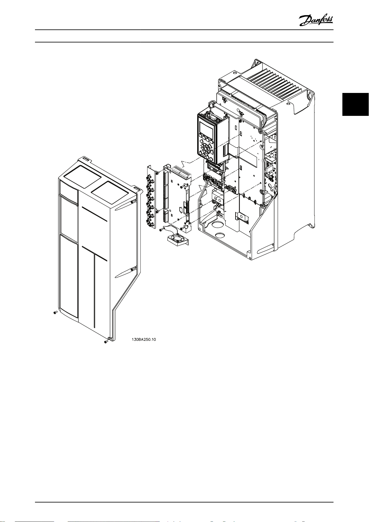
3 Mechanical Installation
This chapter is only relevant if the MCO 350/351 is
delivered as an option for upgrading an existing VLT
33
AutomationDrive. When ordered with the frequency
converter, MCO 350/351 is pre-installed. For retrofit,
purchase a mounting kit.
There is a different mounting kit for different enclosures.
Use MCO 350/351 in slot C0 or combine it with another
option in slot C1.
Mounting kit depending on enclosure Order no.
Bookstyle Enclosure
A2 and A3 (40 mm for 1 C option) 130B7530
A2 and A3 (60 mm for C0 + C1 option) 130B7531
B3 (40 mm for 1 C option) 130B1413
B3 (60 mm for C0 + C1 option) 130B1414
Compact Enclosure
A5 130B7532
B, C, D, E, and F (except B3) 130B7533
®
Table 3.1 Mounting Kits
Do not mount the small fan for B4, C3, C4, D, E, and F.
Illustration 3.1 Bookstyle Enclosure – A2, A3, B3
8 Danfoss A/S © 04/2014 All rights reserved. MG33R302
Page 11
Mechanical Installation Operating Instructions
3 3
Illustration 3.2 Compact Enclosure – A5, B (except B3), C, D, E, F
MG33R302 Danfoss A/S © 04/2014 All rights reserved. 9
Page 12

130BA248.11
130BT334.10
Electrical Installation Operating Instructions
4 Electrical Installation
Refer to the safety warnings in chapter 2 Safety before
installing the MCO.
Screen all control cables and connect the cable screen to
ground at both ends to avoid EMC problems. Always
44
follow the instructions of the encoder supplier. See also
®
VLT
AutomationDrive FC 301/FC 302 0.25-75 kW Design
Guide for more information regarding cable installation.
4.1 MCO 350/351 Control Terminals
4.1.1 Enclosure Types A2 and A3
Encoder and I/O terminal are located behind the C option
terminal cover, see Illustration 4.1.
MCO CAN bus terminals and debug terminals (RS-485) are
on the top of the C option cover. If these connections are
used, cut out the plastic parts above the connectors and
mount the cable relief.
Enclosure Types A5, B1, and B2
4.1.2
All MCO 350/351 terminals are located next to the VLT
AutomationDrive control card. Remove the front cover to
get access. See Illustration 4.2.
MCO control terminals are plug connectors with screw
terminals. Terminals X55, X56, X57, X58, and X59 are
duplicated to be used for both bookstyle and compact
enclosure type.
See Illustration 4.3 to locate the terminal blocks.
®
Illustration 4.1 Location of Encoder and I/O Terminals
Illustration 4.2 Removing the Front Cover
10 Danfoss A/S © 04/2014 All rights reserved. MG33R302
Page 13

X62
X55
X56
X57
X58
X59
2
X60
130BB794.10
1
Electrical Installation Operating Instructions
4.2
Frequency Converter Control Card
Terminals
The terminals on the VLT® AutomationDrive control card
are allocated for the MCO 351.
Do not change the following parameters for I/O settings:
Parameters 5-10 to 5-15 set to [0] No operation
•
(default setting)
Parameters 3-15, 3-16 and 3-17 set to [0] No
•
function (default setting)
Parameter 6-50 set to [52] MCO 0–20 mA
•
4 4
1 Terminal block 1
2 Terminal block 2
X55 Encoder 2
X56 Encoder 1
X57 Digital inputs
X58 24 V DC supply
X59 Digital outputs
X60 MCO CAN Bus
X62 Debug connections (RS 485)
Illustration 4.3 Location of Terminal Blocks 1 and 2
Illustration 4.4 FC 300 Terminals
Technical data on these terminals can be found in the
VLT® AutomationDrive FC 301/FC 302 Design Guide.
Use terminal block 1 with bookstyle and terminal block 2
with compact.
MG33R302 Danfoss A/S © 04/2014 All rights reserved. 11
Page 14

Electrical Installation Operating Instructions
Digital inputs
12 +24 V OUT
13 +24 V OUT
18 Reference index bit 0
19 Reference index bit 1
27 Enable (error clear in digital control mode)
29 Reference index bit 4
44
32 Reference index bit 3
33 Reference index bit 2
20 COM D in
37 Safe Torque Off (STO)
Table 4.1 Digital Inputs
Relay 1:
Mechanical brake (normally open)
Relay 2:
Mechanical brake monitoring (normally closed)
Analog input:
53 ±10 V-In Manual jog positive
54 ±10 V-In Manual jog negative
55 Common for analogue inputs
Supply voltage:
12, 13 +24 V Out
20 Common for digital inputs (common with X55/4-X56/4X58/2)
12 Danfoss A/S © 04/2014 All rights reserved. MG33R302
Page 15

FC300
Reference index Bit 1
Enable (error clear in dig. control mode)
Reference index Bit 4
Reference index Bit 3
Reference index Bit 2
Touchprobe pos. locked
Manual Jog positive
Reset Touchprobe pos.
Go to Home position
Latch new index
2
Homing completed
Reference pos. reached
Reference index Bit 0
Reference index Bit 1
Reference index Bit 2
Reference index Bit 3
Reference index Bit 4
02
03
04
06
+24 V DC out
+8 V DC out
+5 V DC out
COM
+24 V DC out
+8 V DC out
+5 V DC out
COM
A
/A
B
/B
CLK
/CLK
DATA
/DATA
Analog
Output
Analog
Inputs
S201, S202 = O
MCO 351
Relay
01
Relay
02
Mains
Motor
X56
Encoder 1
X55
Encoder 2
+24 V OUT
+24 V OUT
Reference index Bit 0
COM D in
Safe torque o (STO)
COM A in
+10 V OUT
Quickstop
Manual Jog negative
COM A out
Touchprobe switch
Positive HW limit switch
Negative HW limit switch
Home reference switch
Go to target position
Reset Home ag
+24 V supply
COM
Error occured
12
13
18
19
27
29
32
33
20
37
39
42
50
53
54
55
1
2
3
4
5
6
7
8
9
10
1
1
2
3
4
5
6
7
8
Digital
Inputs
X57
Digital
Inputs
X58
24 V DC
Supply
X59
Digital
Outputs
91
92
93
PE
96
97
98
99
U
V
W
01 Brake Supply
Brake Brake COM
05
L1
L2
L3
PE
PE
TTL SSI SINCOS
A
/A
B
/B
Z
/Z
CLK
/CLK
DATA
/DATA
SIN
REFSIN
COS
REFCOS
1
2
3
4
5
6
7
8
9
10
11
12
Z
/Z
1
2
3
4
5
6
7
8
9
10
11
12
130BD658.10
Electrical Installation Operating Instructions
4.3 Wiring Diagram
4 4
Illustration 4.5 Wiring Diagram
NOTICE
Input 29 is not available in FC 301. Therefore only 16 positions can be selected via digital inputs in FC 301.
MG33R302 Danfoss A/S © 04/2014 All rights reserved. 13
Page 16
130BD653.10
1 2 3 4 5 7
9
116
8 10
12
130BD653.10
1 2 3 4 5 7
9
116
8 10
12
1 2 3 4 5 7 96 8 10
130BD655.10
Electrical Installation Operating Instructions
X56 Master Encoder Input/Virtual
4.4 MCO Option Card Terminals
4.4.2
Master Output
Technical data on these terminals can be found in the
Motion Control Option MCO 305 Operating Instructions.
4.4.1 X55 Feedback Encoder Input
44
Pin number TTL encoder SSI encoder
1 +24 V DC Supply +24 V DC Supply
2 +8 V DC Supply +8 V DC Supply
3 +5 V DC Supply +5 V DC Supply
Pin number TTL encoder SSI encoder SinCos encoder
1 +24 V DC
Supply
2 +8 V DC Supply +8 V DC Supply +8 V DC Supply
3 +5 V DC Supply +5 V DC Supply +5 V DC Supply
4 GND GND GND
5 A - +SIN
6 A not - REFSIN
7 B - +COS
8 B not - REFCOS
9 Z CLK 10 Z not CLK not 11 - DATA 12 - DATA not -
Illustration 4.6 X55 Feedback Encoder Input
+24 V DC
Supply
+24 V DC
Supply
4 GND GND
5 A 6 A not 7 B 8 B not 9 Z CLK
10 Z not CLK not
11 - DATA
12 - DATA not
Illustration 4.7 X56 Master Encoder Input/Virtual Master
Output
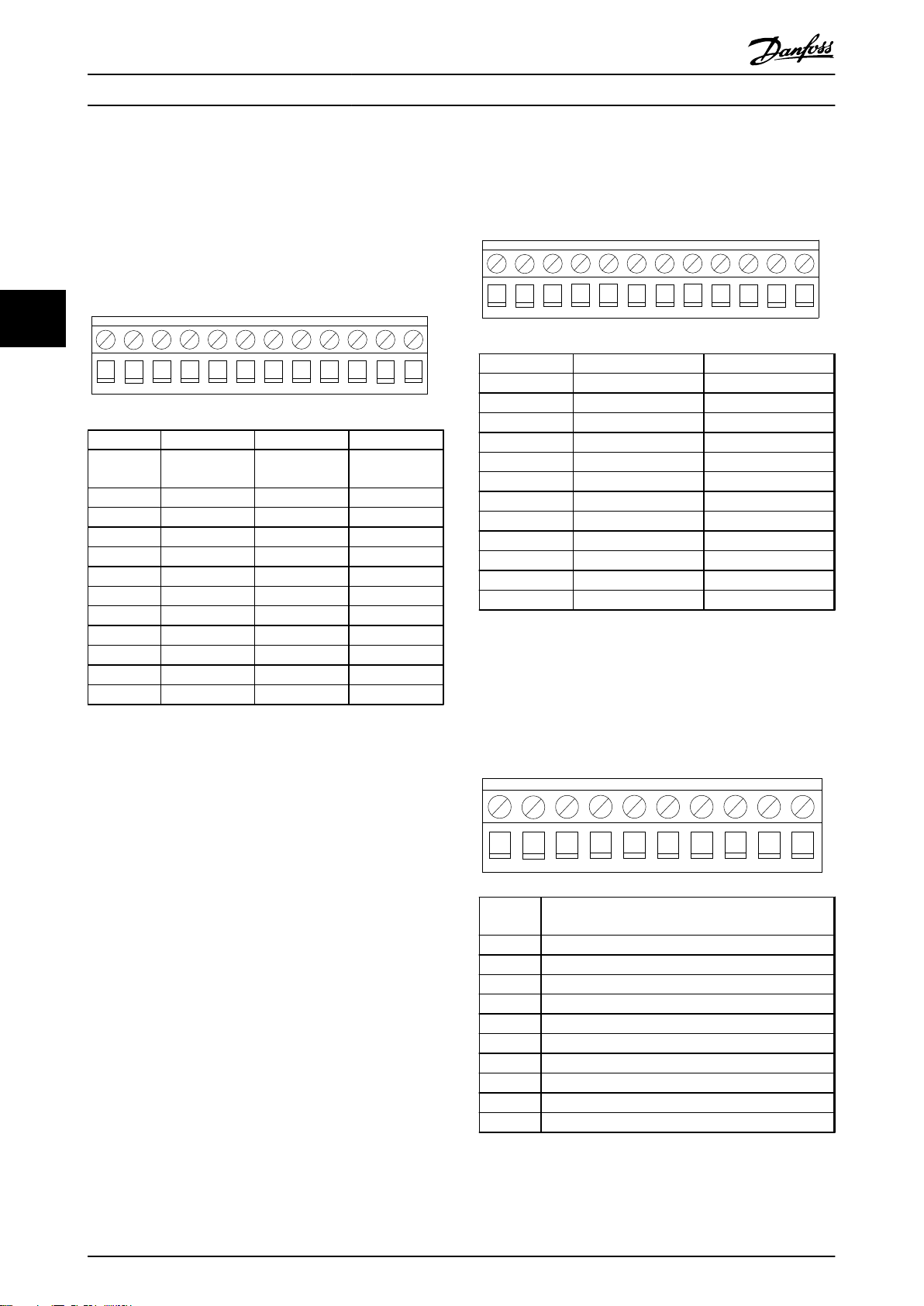
X57 Digital Input
4.4.3
14 Danfoss A/S © 04/2014 All rights reserved. MG33R302
Pin
number
1 Touch probe switch
2 Positive hardware limit switch
3 Negative hardware limit switch
4 Home switch
5 Go to target position
6 Reset home flag
7 Reset touch probe position
8 Quick stop
9 Go to home position
10 Latch new reference position index number
Illustration 4.8 X57 Digital Inputs
Description
Page 17

1 2
130BD656.10
1 2 3 4 5 76 8
130BD657.10
1
2
3 4 5
130BD672.10
Electrical Installation Operating Instructions
4.4.4 X58 24 V DC Supply
Pin
number
1 +24 V
2 COM
Illustration 4.9 X58 24 V DC Supply
4.4.5
Description
X59 Digital Outputs
X62 MCO-CAN
4.4.6
Pin number Description
1 –
2 CAN_L (CAN low)
3 Drain
4 CAN_H (CAN high)
5 –
Illustration 4.11 X62 MCO CAN
4 4
Pin
number
1 Homing completed
2 Reference position reached
3 Error
4 Reference index bit 0
5 Reference index bit 1
6 Reference index bit 2
7 Reference index bit 3
8 Reference index bit 4
Illustration 4.10 X59 Digital Outputs
Description
MG33R302 Danfoss A/S © 04/2014 All rights reserved. 15
Page 18

Electrical Installation
Operating Instructions
4.5 Description of Terminals
4.5.1 Frequency Converter Control Card Terminals
Connector Terminal Designation Description
Inputs
44
Relay 01
Relay 02
Analogue I/O
RS-485
12, 13 +24 V OUT 24 V (+1, –3 V) power supply
Max. load:
VLT® AutomationDrive FC 301: 130 mA
VLT® AutomationDrive FC 302: 200 mA
18 Reference index bit 0 (LSB) Reference position index number bit 0 (least significant bit). Not used in
fieldbus mode.
19 Reference index bit 1 Reference position index number bit 1. Not used in fieldbus mode.
20 COM D IN Ground for 24 V – common with 39, 55, X55/4, X56/4, and X58/2
27 Enable (error clear in digital
control mode)
29 Reference index bit 4 (msb) Reference position index number bit 4 (most significant bit). Not used in
32 Reference index bit 3 Reference position index number bit 3. Not used in fieldbus mode.
33 Reference index bit 2 Reference position index number bit 2. Not used in fieldbus mode.
37 Safe Torque Off (STO) Safe input. Used for STO.
01 COM Relay 01 Common terminal for Relay 01.
02 Connect to electro-mechanical
brake NO
03 NC Normal Closed
04 COM Relay 02 Common terminal for Relay 02.
05 Brake activated NC Normal Closed Relay 02 is closed to indicate an activated electrome-
06 NO Normal Open
39 COM A OUT Ground for analog output. Common with 20 and 55.
42 Touch probe position locked in This analog output delivers either 0 mA (not locked in) or 20 mA (locked
50 +10 V OUT Power supply for manual JOG inputs (terminal 53 and 54).
53 ±10 V-In Manual jog positive When high (above 5 V), the drive travels with jogging speed (parameter
54 ±10 V-In Manual jog negative When high (above 5 V), the drive travels with jogging speed (parameter
55 COM A IN Ground for analogue inputs. Common with 20 and 39.
61 Shield
68 RxTx+ A control card switch is provided for termination resistance.
69 RxTx–
To enable operation, this input must be maintained at high in both
digital control mode and fieldbus control mode.
Digital control mode: Errors are cleared on the rising edge. Must be 0 V
for at least 1 ms to guarantee edge detection.
fieldbus mode. Not available in VLT® AutomationDrive FC 301.
Normal Open Relay 01 is open (brake activated) during power off and
start-up of the FC 300. It is always open after a Quick Stop procedure or
with an error situation. Relay 01 only closes with motion procedures or if
specified in parameter 19-09 Automatic Brake Control.
chanical brake. It is open to indicate a deactivated electromechanical
brake. Not used in fieldbus control mode.
in) at a maximum of 500 Ω.
Maximum 15 mA.
19-16) and ramp (parameter 19-17) in the positive direction. When low
(below 5 V), the drive ramps down and stops if no other motion
procedure is activated. Jog positive has higher priority than jog negative.
Not used in fieldbus mode by default. Can be enabled via parameter
19-31 Digital Jog in field Bus mode.
19-16) and ramp (parameter 19-17) in the negative direction. When low
(below 5 V), the drive ramps down and stops if no other motion
procedure is activated. Not used in fieldbus mode by default. Can be
enabled via parameter 19-31 Digital Jog in field Bus mode.
Integrated RC-filter for cable screen. Only for connecting the screen
when experiencing EMC problems.
Table 4.2 Control Card Terminals
16 Danfoss A/S © 04/2014 All rights reserved. MG33R302
Page 19

Electrical Installation Operating Instructions
4.5.2 MCO Digital Inputs Terminal (X57)
Terminal Designation Description
1 Touch probe switch input Input triggered on the rising edge. If this signal goes high when no touch probe target
position is locked, a new touch probe target position is calculated and locked in
memory.
2 Positive hardware limit switch
input
3 Negative hardware limit switch
input
4 Home reference switch input Active high. Marks the home position in the application.
5 Go to the target position Active high. Upon activation the motor goes to the specified target position. A low
6 Reset home flag Active high. This input clears the home flag. This allows the performance of a 2nd
7 Reset touch probe position Active high. This input clears the touch probe position flag. The reset is necessary to
8 Quick stop
9 Go to home position While this input is high the motor executes the homing sequence and no position or
10 Latch new reference position
index number
Input triggered on the falling edge. Triggers a hardware limit error and the motor is
stopped according to parameter 19-06 Error Behaviour.
Input triggered on the falling edge. Triggers a hardware limit error and the motor is
stopped according to parameter 19-06 Error Behaviour.
signal interrupts any positioning sequence. Not used in fieldbus mode.
homing sequence.
carry out a touch probe positioning command to a new target position. Not used in
fieldbus mode.
Active low. This input activates the Quick Stop function. The motor is stopped according
to the setting of parameter 19-06 Error Behaviour. After that, the electromechanical brake
is always activated when the Quick stop input is activated, regardless of the parameter
19-06 Error Behaviour setting.
jog operations are carried out. Any homing sequence is interrupted by a low state on
this input. Not used in fieldbus mode.
Active on the rising edge (must be 0 V for at least 1 ms to guarantee edge detection):
Latches reference position index number specified on terminal 18, 19, 29, 32, 33 into
memory. Digital output 4-8 is changed to mirror the new reference index specified when
using digital input control. Not used in fieldbus mode.
4 4
Table 4.3 MCO Digital Inputs Terminal (X57)
MCO Digital Outputs Terminal (X59)
4.5.3
Terminal Designation Description
1 Homing completed Active high. This output is always high if an absolute encoder is used.
2 Referenced position
reached
3 Error occurred Active high. This output is set every time an error occurs. It is cleared every time a successful error
4 Reference index bit 0 Mirror of the currently locked-in reference index bit 0. Not used in fieldbus mode.
5 Reference index bit 1 Mirror of the currently locked-in reference index bit 1. Not used in fieldbus mode.
6 Reference index bit 2 Mirror of the currently locked-in reference index bit 2. Not used in fieldbus mode.
7 Reference index bit 3 Mirror of the currently locked-in reference index bit 3. Not used in fieldbus mode.
8 Reference index bit 4 Mirror of the currently locked-in reference index bit 4. Not used in fieldbus mode.
Table 4.4 MCO Digital Outputs Terminal (X59)
Active high. This output is set when the target position is reached according to the setting of
parameter 33-47 Size of Target Window.
clear is carried out. This output remains high as long as the power recovery function is selected
(parameter 19-08 Power-Recovery) and active.
MG33R302 Danfoss A/S © 04/2014 All rights reserved. 17
Page 20

MOTOR
X55 X56
130BD828.10
MOTOR
X55 X56
130BD829.10
Electrical Installation Operating Instructions
4.5.4 MCO Encoder Connection
MCO 351 provides 2 encoder interfaces, X55 and X56.
Terminal block X55 is configured as the default feedback
encoder input.
Encoder supported
TTL/RS422 incremental encoder (X55, X56)
•
SSI absolute encoder - Grey code (X55, X56)
44
•
Sin/Cos Encoder 1 Vpp (only X55)
•
Resolver (needs extra option MCB103) - only in
•
speed closed loop.
CANopen encoder (X62)
•
Example 2
Encoder connected to X55 for positioning loop. Since the
encoder is not mounted directly on the motor shaft, this
configuration can be used for the MCO positioning loop
and the FC speed control loop.
NOTICE
Use parameter 32-50 Source Slave for setting encoder
feedback to [1] Encoder 1 X56 or [3] Motor Control.
4.5.4.1 Encoder Connection Examples
Example 1
Encoder connected to X55 for positioning loop. Since the
encoder is mounted directly on the motor shaft, the same
feedback can be used for the MCO positioning loop and
the FC speed control loop.
Illustration 4.12 Encoder Mounted on the Motor
Illustration 4.13 Encoder Mounted on the Gear Box
18 Danfoss A/S © 04/2014 All rights reserved. MG33R302
Page 21

130BD830.10
MOTOR
X55 X56
MOTOR
X55 X56
MCB 103
130BD831.10
Electrical Installation Operating Instructions
Example 3
Encoder connected to X55 for positioning loop. Since the
encoder is not mounted directly on the motor shaft, a 2nd
encoder connection (X56) is needed for running closed FC
speed control loop.
Example 4
Resolver feedback used. MCB 103 option is needed. FC
speed control loop must be closed.
4 4
Illustration 4.14 Encoders Mounted on the Motor and the Gear
Box
Illustration 4.15 Resolver Mounted on the Motor
MG33R302 Danfoss A/S © 04/2014 All rights reserved. 19
Page 22

175ZA813.12
Quick bus go to target
Electrical Installation Operating Instructions
4.6 Fieldbus Interface
4.6.1 Introduction
This section is only relevant if the frequency converter is equipped with a fieldbus interface (option) as well as the
positioning controller.
The positioning controller is controlled via the digital/analog inputs or via fieldbus. Select the control source in parameter
19-04 Control Source. There can only be 1 control source at a time, meaning that the digital/analog inputs are inactive when
44
fieldbus is selected as control source and vice-versa. The only exceptions are listed in Table 4.5. In fieldbus mode, it is
possible to specify the target position and velocity. If the acceleration and deceleration PCDs are left blank, the values for
acceleration and deceleration from index 1 are used.
Data Layout
4.6.2
Control and status signals are transferred via the so-called process data channel (PCD) of the various fieldbus interfaces. The
telegram structure and the available number of data words depends on the fieldbus used. Refer to the manual of the
fieldbus option in use for further details. The example in Illustration 4.16 is based on the layout of a Profibus telegram, the
so-called PPO:
Illustration 4.16 Example using PROFIBUS PPO Type 5
20 Danfoss A/S © 04/2014 All rights reserved. MG33R302
Page 23

Electrical Installation Operating Instructions
Fieldbus control signals (inputs)
Fieldbus
[word.bit]
1.1 Quick bus go to target (high) N/A
1.2 Reset error (high) 27
1.3 Go to home position (high) 9
1.4 Read new trajectory index (high) 10
1.5 Start index positioning (high)/Stop index
1.6 Reset home status (high) 6
1.7 Reset touch probe position (high) 7
1.8 Quick stop (low) 8
1.9 Positive jog (high) 53
1.10 Negative jog (high) 54
1.11 Quick bus type absolute (high) N/A
1.12 Quick bus type relative (high) N/A
1.13 Quick bus type touch probe positive (high) N/A
1.14 Quick bus type touch probe negative (high) N/A
1.15 Teach in (via LCP or fieldbus) (high) [Back] and [Cancel] on the LCP
1.16 Change sign on quick bus target position (high) N/A
2 Quick bus target position (MSB) N/A
3 Quick bus target position (LSB) N/A
4 Quick bus target velocity N/A
5 Quick bus target acceleration N/A
6 Quick Bus target deceleration N/A
7.1 Reference index bit 0 18
7.2 Reference index bit 1 19
7.3 Reference index bit 2 33
7.4 Reference index bit 3 32
7.5 Reference index bit 4 29
7.6 Reference index bit 5 N/A
Fieldbus mode Corresponding input
5
positioning (manual mode activated) (low)
4 4
Table 4.5 Fieldbus Control Signals (Inputs)
MG33R302 Danfoss A/S © 04/2014 All rights reserved. 21
Page 24

Electrical Installation Operating Instructions
Fieldbus control signals (outputs)
Fieldbus
[word.bit]
1.1 Homing done (high) 1
1.2 Referenced position reached (high) 2
1.3 Error occurred (high) 3
1.4 Electro-mechanical brake closed (high) 04
44
1.5 Touch probe position locked (high) N/A
1.6 Watchdog output (toggling) N/A
1.7 Positive hardware limit (high) N/A
1.8 Negative hardware limit (high) N/A
2.1 Current index bit 0 4
2.2 Current index bit 1 5
2.3 Current index bit 2 6
2.4 Current index bit 3 7
2.5 Current index bit 4 8
2.6 Current index bit 5 N/A
3 Actual position (high word)
4 Actual position (low word)
5 Error status
Table 4.6 Fieldbus Control Signals (Outputs)
Fieldbus mode Corresponding output/parameter
Parameter 34-50 Actual Position (high word)
Parameter 34-50 Actual Position (low word)
19-93 Error Status
22 Danfoss A/S © 04/2014 All rights reserved. MG33R302
Page 25

Commissioning
5 Commissioning
Operating Instructions
5.1 Safety Instructions
Refer to the safety warnings in chapter 2 Safety before
commissioning.
5.2 Basic Parameters Set-up
VLT Parameter Groups
Parameter 1-** Motor data, open or closed loop,
•
AMA
Parameter 2-** Dynamic brake
•
Parameter 3-** Reference range and limits, Ramps
•
Parameter 4-** Speed limits, Torque limits
•
Parameter 7-** If using the Drive speed closed
•
loop, tune it before MCO PID
MCO Basic Parameters
Parameter 32-0* Encoder2 (feedback) set-up type
•
and resolution
Parameter 32-3* Encoder1 (if used) set-up type
•
and resolution
Parameter 32-6* Set PID values
•
Parameter 32-8* Maximum velocity, Ramps
•
5.3
Basic Set-up
Refer to the safety warnings in chapter 2 Safety before
commissioning.
For information on applying power and operation of the
LCP, refer to the VLT® AutomationDrive FC 301/FC 302
Operating Instructions.
1. Check the motor connection. Control the brake
externally from the option until set-up is finished,
because the mechanical brake control cannot be
guaranteed during this basic set-up. Also ensure
that the motor can rotate freely without causing
damage or injury.
2. Remove all signals to inputs. Only Input 27
(coast), I8 (Qstop), I3 (Negative HW limit) and I2
(Positive HW limit) must be connected and high.
3.
Select Off Mode
4. Run the Quick Set-up with the correct motor
data.
5.
Go to Hand on mode and set the frequency for a
low positive value, for example +3 Hz in the
reference value. The motor should now rotate.
6. If the motor rotates in the wrong (negative)
direction, exchange the motor phases.
7. Set the parameters for feedback encoder in
parameter group 32-0* Encoder 2 parameters and,
if needed, parameters for encoder in parameter
group 32-3* Encoder 1 parameters.
7a
For incremental encoder:
Set parameter 32-00 Incremental Signal
Type to the type needed. Set the
resolution of the encoder in parameter
32-01 Incremental Resolution. Set
parameter 32-00 Incremental Signal Type.
7b
For absolute encoder:
Set parameter 32-00 Incremental Signal
Type to [0]. Set parameter 32-02 Absolute
Protocol to the encoder type used and
32-03 Absolute Resolution to the encoder
resolution. Set the data bit and clock
settings for the absolute encoder from
parameter 32-05 Absolute Encoder Data
Length to 32-08 Absolute Encoder Cable
Length.
8. Press the [Status] button on the LCP. Now the
RPM and Actual Position values appear in the
upper line of the display.
9. Optimise the PID controller(s).
5.4
PID Settings
Calculate Feed forward velocity (FFVEL – 32-65 Velocity
Feed Forward)
FFVEL =
Use parameter 19-19 FFVEL Auto-calculation to specify if the
calculation should be made automatically. This is only
possible when encoder and speed parameters have been
set.
MaxVelEnc x EncRes x Tsample
FFVEL = 32-65 Velocity Feed Forward
•
MaxVelEnc = parameter 32-80 Maximum Velocity
•
(Encoder)
EncRes = Encoder resolution
•
Tsample = PID sampling time (32-69 Sampling
•
Time for PID Control)
62914560000
For incremental and sinusoidal encoders:
-
EncRes = 4 x (32-01 Incremental
Resolution)
For CAN encoders: EncRes = 1 x
-
(parameter 32-01 Incremental Resolution)
For absolute encoders: EncRes = 32-03
-
Absolute Resolution
5 5
MG33R302 Danfoss A/S © 04/2014 All rights reserved. 23
Page 26

Commissioning Operating Instructions
Setting of PID:
19-05 User Actual Position Setting
Range: Function:
32-60 Proportional factor ≈ FFVEL/50
32-61 Derivative factor ≈ FFVEL/10
32-62 Integral factor = 5
5.5 Description of Application Parameters
5.5.1 19-** Application Parameters
The 19-** parameters configure the MCO 351 Positioning
Controller specific application software. The other
55
parameters configure the underlying MCO firmware.
19-00 Control Mode
Option: Function:
[0] * MCO
control
[1] VLT control The motor is controlled by VLT and not by
The motor is controlled by MCO.
MCO. Manual running is possible. Note that
the standard controller functions, for example,
limit switches and other safety-related
functions, are not active.
0 [–1073741824 to
1073741824]
At power-up, if parameter 33-00 Force
Home is set to [0] Home not forced, the
actual position is equal to the value set
here.
19-06 Error Behaviour
Option: Function:
[0] * Electronic
brake
[1] Mechanical
brake
This parameter determines the behaviour of
the motor after an error is detected.
The motor ramps down to standstill with the
shortest possible ramp (parameter 32-81).
After achieving standstill it activates the
electronic brake according to the setting of
parameter 19-10 Coast Delay. If the motor is
coasted at any point during ramp down (for
example, due to an overcurrent trip), the
motor immediately activates the brake and
coasts the motor.
The motor immediately activates the brake
and coasts the motor.
NOTICE
19-01 Endless Positioning
Option: Function:
[0] * Limited The positioning is performed in a limited position
range without position overflow.
[1] Endless The positioning is performed continuously in 1
direction. Also remember to set parameters 19-08
Power Recovery, 33-43 Negative Software End Limit
Active, and 33-44 Positive Software End Limit Active
to [0].
19-02 Block Direction
Option: Function:
[0] * No blocking The motor is enabled to move in both
directions.
[1] Block
reverse
[2] Block
forward
Defined as an error situation (“Reverse
operation prohibited” – ERROR STATUS = 12)
if the motor is moving in reverse direction.
Defined as an error situation (“Forward
operation prohibited” – ERROR STATUS = 13)
if the motor is moving in forward direction.
19-03 Touch Probe Delay
Range: Function:
0 [1–100000 ms] This parameter enables compensation for any
fixed delay in the touch probe.
19-04 Control Source
Option: Function:
[0] * Digital I/O The positioning is controlled via digital inputs.
[1] Fieldbus The positioning is controlled via fieldbus.
The brake is always activated after an error situation (or
quick stop), regardless of the setting in parameter 19-09
Automatic Brake Control.
19-07 Error Reset
Option: Function:
[0] * No reset No error reset.
[1] Reset
error
By selecting this option, it is possible to clear
the error flag (if the reason for the error is not
still present). The parameter automatically resets
to [0] No reset when the error is successfully
cleared.
19-08 Power-Recovery
Option: Function:
[0] Disabled When the power recovery function is disabled (set
to [0]), it is not possible to drive the application
by any means (neither jogging nor positioning) as
long as the application is outside the HW or SW
limits. The only way to recover from this situation
is to move the application by hand.
[1]*Enabled When the power recovery function is enabled (set
to [1]), it is possible to make a partial reset of the
limit error (ERROR STATUS = 2/3/4/5), whereby it
is possible to use the jogging function to drive
the application out of the HW or SW limit area. It
is not possible to drive the application with
homing, positioning, or jogging (in the wrong
direction), as long as the application is still within
the HW or SW limit area. The error occurred output
remains high to indicate that these restrictions are
in effect. As soon as the application is moved
24 Danfoss A/S © 04/2014 All rights reserved. MG33R302
Page 27

Commissioning Operating Instructions
19-08 Power-Recovery
Option: Function:
outside the HW or SW limit area, the error is
automatically cleared and the error occurred signal
goes low to indicate that normal operation is
restored.
19-09 Automatic Brake Control
Option: Function:
[0] Disabled When the automatic brake control function is
disabled (set to [0]), the frequency converter
control loop is active, even at standstill.
[1] * Enabled When the automatic brake control function is
enabled (set to [1]), the electromechanical brake
is automatically activated every time the
application has been at standstill for a time
period specified in parameter 19-12 Hold Delay.
This is especially useful in hoist applications
where the motor could overheat if it has to
deliver full torque at standstill for a prolonged
period.
19-10 Coast Delay
Range: Function:
200ms [0–
1000
ms]
Used with the automatic brake control function.
The coast delay is the delay after activating the
electro-mechanical brake before disabling the
controller and coasting the motor. Useful in
hoisting applications where the load would
otherwise drop a little after each stop. This is
because the activation of the brake is slower
than the deactivation of the motor.
19-11 Brake Delay
Range: Function:
200ms [0–
1000
ms]
Used with the automatic brake control function.
The brake delay is the delay after activating the
control and magnetising the motor, before the
brake is deactivated. Useful in applications with
(typically large) motors that take a longer time
to be fully magnetised than the time it takes for
the electro-mechanical brake to deactivate.
19-12 Hold Delay
Range: Function:
0 s [0–
10000 s]
Used with the automatic brake control function.
The hold delay is a waiting period in which the
brake is not activated, even though the
application is at standstill. Useful in applications
where a sequence of fast positioning commands
is followed by longer standstill periods.
19-13 Brake Wear Limit
Range: Function:
0 [0–
1073741824
UU]
If a value higher than [0] (disabled) is set,
the motor defines an error situation (Brake
wear limit exceeded – ERROR STATUS = 7) if
the drive moves more than the number of
user units (UU) specified in this parameter
while the electronic brake is activated.
19-14 Motor/Encoder Gear Numerator
Range: Function:
1 [1–
100000]
If the encoder is mounted on a gear where 5
revolutions of the motor correspond to 2
revolutions of the encoder, this parameter should
be set to [5] (the number of motor revolutions)
and parameter 19-15 Motor/Encoder Gear
Denominator should be set to [2] (the number of
encoder revolutions). If the encoder is mounted
directly on the motor shaft, this parameter setting
should remain at [1].
19-15 Motor/Encoder Gear Denominator
Range: Function:
1 [1–100000]
See the description of parameter 19-14 Motor/
Encoder Gear Numerator. If the encoder is
mounted directly on the motor shaft, this
parameter setting should remain at [1].
19-16 Maximum Jog Velocity
Range: Function:
100 ERPM [1–20000
ERPM]
The maximum speed allowed while
jogging the application is specified in
terms of Encoder Revolutions Per
Minute (ERPM).
NOTICE
This setting must never exceed a value that is approximately 5% lower than the value in parameter 32-80
Maximum Velocity (Encoder).
19-17 Jog Ramp Time
Range: Function:
5000ms [10–
100000
ms]
19-18 Jog Velocity Scaling
Option: Function:
[0] * No scaling The jog velocity is defined in encoder
[1] Scaling The jog velocity is scaled by Motor/Encoder
This parameter specifies the ramp-up time
and the ramp-down time used during
jogging. The ramp time is defined as the
time in milliseconds it would take to ramp
from standstill to the maximum allowed
velocity in parameter 32-80 Maximum
Velocity (Encoder).
revolutions per minute (ERPM).
Gear Numerator/Gear Denominator.
5 5
MG33R302 Danfoss A/S © 04/2014 All rights reserved. 25
Page 28

Commissioning Operating Instructions
19-19 FFVEL Auto-calculation
Option: Function:
[0] * Disabled Automatic calculation is disabled for both
velocity feed forward (FFVEL) and velocity
control loop (PID).
[1] FFVEL
enabled
[2] FFVEL +
PID
55
enabled
The optimal setting of parameter velocity feed
forward is calculated automatically. This
parameter automatically resets to [0] Disabled
when the calculation is complete.
The optimal setting of parameter velocity feed
forward, proportional, derivative, and integral
factor is calculated automatically. This
parameter automatically resets to [0] Disabled
when the calculation is complete.
Parameter 32-80 Maximum Velocity
Parameter 32-00 OR 32-02 Encoder type
Parameter 32-01 OR 32-03 Encoder resolution
Parameter 19-14 motor/encoder gear ratio
numerator
Parameter 19-15 motor/encoder gear ratio
denominator
NOTICE
A change to any one of these parameters prompts a
recalculation, since the optimum value of the regulation
parameters has changed.
19-20 Factory Reset
Option: Function:
[0] * Disabled No parameters reset.
[1] Enabled Resets all parameter values to default and also
resets all trajectory data. The parameter automatically resets to [0] Disabled when the reset is
successfully carried out.
19-21 Link LCP Input to Index
Option: Function:
[0] * Disabled Disables the automatic update of parameter
19-23 Index Number. This is necessary when
programming a position number different from
the one loaded into the PLC memory.
[1] Enabled
Parameter 19-23 Index Number is automatically
updated with the last position reference number
that has been loaded into memory. This enables
the operator to see what position reference is
given by the PLC system.
19-23 Index Number
Range: Function:
0 [0–31
(0–63 in
fieldbus
mode)]
Specifies which position data should be
displayed in parameters 19-24 Index Target
Position to 19-28 Index Trajectory Type. Whenever
this number is changed, the current values of
the index parameters are stored in the memory
under the previously specified index number.
After that, the values of the index parameters
are updated with the data stored in the memory
relevant to the newly specified index number.
19-24 Index Target Position
Range: Function:
0 [–
1073741824
to
1073741824
UU]
The meaning of this parameter depends on
the position type specified in parameter 19-28
Trajectory Type.
If parameter 19-28 Index Trajectory Type = [0]
Absolute, the value of this parameter refers to
an absolute position (relative to the fixed
Home position).
If parameter 19-28 Index Trajectory Type = [1]
Relative, and the last position was obtained
through jogging, the value of this parameter
is a position relative to that position. If the
last position was reached as a result of a
positioning command, then the value of this
parameter specifies a position relative to the
last target position (whether it was reached or
not).
If parameter 19-28 Index Trajectory Type = [2]
Touch probe positive, the application moves in
the positive direction until a touch probe
position is defined. If a touch probe position is
already defined, the application moves directly
to that position.
A touch probe position is defined as the
position at which the touch probe switch input
goes high plus the value of parameter 19-24
Index Target Position.
A touch probe position is cleared by a high
signal on the reset touch probe position input.
The output Touch probe position locked is high
if a touch probe position is defined.
If parameter 19-28 Trajectory Type = [3] Touch
probe negative, the application moves in a
negative direction until a touch probe position
is defined. If a touch probe position is already
defined, the application moves directly to that
position.
NOTICE
This parameter is automatically updated depending on
parameter 19-23 Index Number.
26 Danfoss A/S © 04/2014 All rights reserved. MG33R302
Page 29

Commissioning Operating Instructions
19-25 Index Ramp Up Time
Range: Function:
5000 [10–
100000 ms]
The index ramp-up time is defined as the
time in milliseconds it would take to ramp
from standstill to the maximum allowed
velocity set in parameter 32-80 Maximum
Velocity (Encoder). This setting is relevant
during positioning with the current trajectory
index.
NOTICE
This parameter is automatically updated depending on
parameter 19-23 Index Number.
19-26 Index Ramp Down Time
Range: Function:
5000 [10–
100000 ms]
The index ramp-down time is defined as the
time in milliseconds it would take to ramp
from the maximum allowed velocity set in
parameter 32-80 Maximum Velocity (Encoder)
to standstill. This setting is relevant during
positioning with the current trajectory index.
NOTICE
This parameter is automatically updated depending on
parameter 19-23 Index Number.
19-27 Index Maximum Velocity
Range: Function:
100 ERPM [1–20000
ERPM]
The index maximum velocity is defined
as the velocity in encoder revolutions
per minute (ERPM). This setting is
relevant during positioning with the
current trajectory index.
NOTICE
This parameter is automatically updated depending on
parameter 19-23 Index Number. The setting should never
exceed a value that is approximately 5% lower than the
value calculated in parameter 32-80 Maximum Velocity
(Encoder).
19-28 Index Trajectory Type
Option: Function:
[0] * Absolute
[1] Relative Positioning is relative to the last target
[2] Touch probe
positive
[3] Touch probe
negative
Positioning is absolute, related to the Home
position.
position, whether it was reached or not.
When jogging was executed previously,
positioning is relative to the position
reached via jogging.
Positioning is relative to a touch probe
position expected in positive direction.
Positioning is relative to a touch probe
position expected in negative direction.
Also see parameter 19-24 Index Target Position.
NOTICE
This parameter is automatically updated depending on
parameter 19-23 Index Number.
19-29 Parameter Save
Option: Function:
[0] * No action No trajectory data saved. Trajectory data are
not automatically saved and are therefore
not automatically available after powercycle.
[1] Save
persistent
19-30 Main Screen Setup Save
Option: Function:
[0] * No action Main screen set-up is not saved persistent.
[1] Save
persistent
19-31 Digital Jog in Field Bus mode
Option: Function:
[0] * Off
[1] Activates jog with digital inputs (53, 54), also in field
bus mode.
19-90 Type/Version
Range: Function:
[351xxyy] The text in this parameter shows the MCO product
19-91 Software Version
Range: Function:
[xxyy] The text in this parameter shows the software version
number (xx = major version code, yy = minor version
code).
19-92 New Index
Range: Function:
0 [0–31
(0–63 in fieldbus mode)]
Saves trajectory data persistent and
parameters too. This parameter automatically resets to [0] when the data is saved
successfully.
The main screen set-up is not automatically
saved and is therefore not automatically
available after a power-cycle.
Saves main screen set-up persistent. This
parameter automatically resets to [0] No
action when the main screen set-up is
saved successfully.
type/software version.
Currently latched index number.
5 5
MG33R302 Danfoss A/S © 04/2014 All rights reserved. 27
Page 30

Commissioning Operating Instructions
19-93 Error Status
Option: Function:
[0] * 0 = OK
1 = Homing needed
2 = Positive HW limit
3 = Negative HW limit
4 = Positive SW limit
5 = Negative SW limit
6 = VLT not running
7 = Brake wear limit
8 = Quick stop
55
9 = PID error too big
12 = Reverse operation
13 = Forward operation
92 = Encoder hardware error
This is a read-only parameter.
It displays the current fault
code.
28 Danfoss A/S © 04/2014 All rights reserved. MG33R302
Page 31

Commissioning Operating Instructions
5.6 MCO Basic Settings
5.6.1 32-0* and 32-1*, Encoder 2
Parameters
The 32-0* and 32-1* parameters configure the interface for
encoder 2.
32-00 Incremental Signal Type (0x1234)
Slave Denominator (Subindex 02)
This parameter specifies the type of incremental encoder
connection to Encoder 2 interface (X55 and X62 if a CAN encoder
is used).
Option: Function:
[0] None No incremental encoder is
used.
[1] * RS422 (5 V TTL) Digital incremental encoder
with an interface according
to RS422 is connected.
[2] Sinusoidal 1 Vpp Analog incremental encoder
with 1 V peak-peak signal is
connected.
[3] CAN encoder CAN encoder is used.
32-01 Incremental Resolution
Range: Function:
1024* [1073741823] The encoder resolution is used to
calculate velocity in RPM (revolutions per
minute) as well as time-out for detection
of the zero pulse with homing. Set the
resolution of the incremental encoder
connected to Encoder 2 interface (X55 and
X62 if a CAN encoder is used). The
encoder resolution can be found on the
encoder nameplate or datasheet.
If parameter 32-00 Incremental Signal Type
is set to:
[0] Digital incremental encoder,
•
the resolution must be set in
pulses per revolution.
[1] Analog incremental encoder,
•
the resolution must be set in
sinusoidal signal periods per
revolution.
[2] CAN encoder and the CAN
•
encoder is an incremental
encoder, the resolution must be
set in pulses per revolution. If
the CAN encoder is an absolute
encoder, the resolution must be
set in (pulses per revolution)/4.
NOTICE
The parameters for the incremental resolution (32-01 or
32-31) are always used, even if the CAN encoder is an
absolute encoder. But a quarter of the encoder
resolution must be set for a CAN absolute encoder. The
reason is the internal calculation, which uses 4 times the
number of counts, because an incremental encoder
returns 4 times more quad counts than its counts. An
absolute encoder only returns this real resolution as a
maximum value.
NOTICE
When [3] Motor Control is selected in parameter 32-50
Source Slave, the resolution can be set with this
parameter. The resolution value must be a second
power, otherwise rounding errors lead to positioning
drifts. The maximum frequency of the encoder signal
must not exceed 410 kHz. The parameter is only visible
when parameter 32-00 Incremental Signal Type is not set
to [0] None.
32-02 Absolute Protocol
This parameter specifies the type of absolute encoder connected
to Encoder 2 interface (X55 and X62 if a CAN encoder is used).
Option: Function:
[0] * None No absolute encoder is connected.
[1] HIPERFACE HIPERFACE absolute encoder is connected.
The selection includes the default settings
encoder ID 1 and encoder parity even.
[4] SSI An absolute encoder with SSI interface is
connected
[5] SSI with filter An absolute encoder with SSI interface is
connected and the communication/ signal is
unstable.
A leap in the position data is detected if it is larger than
the encoder resolution/2. The correction is made with an
artificial position value, which is calculated from the last
velocity. If the error continues for more than 100 readouts
(>100 ms), there is no further correction, which then leads
to a position error (error 108).
32-03 Absolute Resolution
Range: Function:
8192* [1 to
1073741823]
The encoder resolution is used to
calculate the velocity in RPM
(revolutions per minute).
Set the resolution of the absolute
encoder connected to Encoder 2
interface (X55/X62) in positions per
revolution. The encoder resolution can
be found on the encoder nameplate or
datasheet.
5 5
MG33R302 Danfoss A/S © 04/2014 All rights reserved. 29
Page 32

Commissioning Operating Instructions
NOTICE
The parameter is only visible when parameter 32-02
Absolute Protocol is not set to [0] None.
32-04 Absolute Encoder Baudrate X55
Select the baud rate of the attached encoder.
Option: Function:
[0] 600 Baud
[1] 1200
[2] 2400
55
[3] 4800
[4] * 9600
[5] 19200
[6] 38400
32-05 Absolute Encoder Data Length
Range: Function:
25* [8-37 Bit] Specify the number of data bits for the
connected absolute encoder, see encoder
datasheet. This is required for the MCO to
generate the correct number of clock bits.
NOTICE
The parameter is only visible when parameter 32-02
Absolute Protocol is not set to [0] None.
32-06 Absolute Encoder Clock Frequency
Range: Function:
262.000* [78.124–
2000.000 kHz]
Specifies the frequency of the
absolute encoder clock signal
generated by the MCO. Set a
frequency appropriate for the
connected encoder.
NOTICE
This parameter is only visible when parameter 32-02
Absolute Protocol is not set to [0] None.
32-07 Absolute Encoder Clock Generation
Select whether the MCO should generate an absolute encoder
clock signal or not.
Option: Function:
[0] Off Select this option if more MCOs are connected to the
same absolute encoder and another MCO generates
the clock signal. Only 1 device is allowed to generate
the clock signal and only 1 device (encoder or MCO) is
allowed to generate the data signal when multiple
MCOs are interconnected.
[1] * On Select this option if the MCO is the only clock
generator for the connected absolute encoder.
NOTICE
This parameter is only visible when parameter 32-02
Absolute Protocol is not set to [0].
32-08 Absolute Encoder Cable Length
Range: Function:
0* [0-300m]The absolute encoder (SSI) clock and data signals
will be out of synchronisation if the signal delay
caused by the encoder cable is too long. The MCO
automatically compensates the cable delay when
the cable length is known. The cable delay
compensation is based on a cable delay of approximately 6 ns (6 x 10⁻⁹ seconds) per meter. Specify
the total cable length (in meters) between the
MCO and the absolute encoder.
NOTICE
This parameter is only visible when parameter 32-02
Absolute Protocol is not set to [0] None.
32-09 Encoder Monitoring
Monitoring of open-circuit and short-circuit of the encoder inputs
can be enabled or disabled.
An encoder error issues fault code 192.
Option: Function:
[0] * Off Hardware monitoring is not
required.
[1] 3 channels All 3 channels (A, B, and
Index) are monitored.
[2] 2 channels Channels A and B are
monitored.
32-10 Rotational Direction
Normally, a positive reference value initiates a positive change of
the position. If not, the reference value can be reversed
internally.
Option: Function:
[1] * No action No change. Positive reference values
produce positive encoder values.
[2] Reference
reversed
[3] User Units
reversed (–1)
The sign of the reference value is
reversed internally (plus becomes minus
and vice-versa). This is equal to a reversal
of the motor cables, or a transposition of
the A and B tracks on the encoder.
The sign of the user unit is reversed.
Thus, positive reference values produce
positive encoder values which are
indicated as negative values, however.
This applies to all outputs (parameters
34-50 Actual Position, 34-51 Commanded
Position, …), all user inputs (parameter
19-24 Index Target Position, …), and all
synchronization factors, as well as the
velocities (parameter 33-03 Velocity of
Home Motion).
30 Danfoss A/S © 04/2014 All rights reserved. MG33R302
Page 33

130BD771.10
25
1
500 25
50 1
qc =
1000
1
qc = qc = 1 UU
4 10 4
130BD772.10
5
1
500 5
3600 3600
qc =
qc = 1 UU
25
9
qc = 1 UU =
Parameter 32-12 User Unit Numerator
Parameter 32-11 User Unit Denominator
4 500 4
Commissioning Operating Instructions
32-10 Rotational Direction
Normally, a positive reference value initiates a positive change of
the position. If not, the reference value can be reversed
internally.
Option: Function:
[4] User Units and
Reference
reversed (–2)
The sign of the reference value is
reversed internally; in addition, the sign
of the user unit is negated as in option
[3].
32-11 User Unit Denominator
Range: Function:
1* [1 to
1073741823]
All path information in motion commands is
made in user units and are converted to quadcounts internally. By selecting these scaling
units correspondingly, it is possible to work
with any technical measurement unit (for
example mm). This factor is a fraction, which
consists of a numerator and denominator.
1 UU =
P32-12 User Unit Numerator
P32-11 User Unit Denominator
Scaling determines how many quad-counts
make up a user unit. For example, if it is
50375/1000, then 1 UU corresponds to exactly
50.375 qc.
32-12 User Unit Numerator
Range: Function:
1* [1 to
10737418237/
max. position
(UU)]
All path information in motion commands is
made in user units and is converted to quadcounts internally. By selecting these scaling
units correspondingly, it is possible to work
with any technical measurement unit (for
example mm). This factor is a fraction, which
consists of a numerator and denominator.
1 UU =
P32-12 User Unit Numerator
P32-11 User Unit Denominator
Scaling determines how many quad-counts
make up a user unit.
Example 1
Shaft or spindle
25 motor revolutions result in 1 spindle
revolution; gearing factor = 25/1
Encoder resolution (incremental encoder) =
500
Spindle gradient = 1 revolution of the spindle
= 5 mm
Scaling factor when working with 1/10 mm
resolution = 5 x 10 = 50
Illustration 5.1 Example 1
32-12 User Unit Numerator
Range: Function:
Parameter 32-11 User Unit Denominator = 1
Example 2
Cylinder
Gear factor = 5/1
Encoder resolution (incremental encoder) =
500
One revolution of the cylinder is 360 degrees.
Work with a resolution of 1/10 degrees, which
means that 1 revolution of the cylinder is
divided into 3600 units.
Scaling factor = 3600
Illustration 5.2 Example 2
Parameter 32-12 User Unit Numerator = 25
Parameter 32-11 User Unit Denominator = 9
32-14 Encoder 2 node ID
Range: Function:
127* [1-127] Enter the feedback CAN encoder node ID.
32-15 Encoder 2 CAN Guard
Feedback CAN encoder guardians can be enabled or disabled.
Option: Function:
[0] * Off Default setting. No monitoring.
[1] On Feedback CAN encoder is monitored.
5.6.2 32-3* and 32-4*, Encoder 1
Parameters
The 32-3* and 32-4* parameters configure the interface for
encoder 1.
32-30 Incremental Signal Type
Specifies the type of incremental encoder connected to Encoder 1
interface (X56 and X62 if a CAN encoder is used).
Option: Function:
[0] None No incremental encoder is
connected.
[1] * RS422 (5 V TTL) A digital incremental encoder with
an interface according to RS-422 is
connected.
[3] CAN encoder An encoder with a CAN interface is
connected.
5 5
Parameter 32-12 User Unit Numerator = 1000
MG33R302 Danfoss A/S © 04/2014 All rights reserved. 31
Page 34

Commissioning Operating Instructions
32-31 Incremental Resolution
Range: Function:
1024* [1 to
1073741823]
55
Set the resolution of the incremental
encoder connected to Encoder 1 interface
(X56). The encoder resolution can be
found on the encoder nameplate or
datasheet.
Digital incremental encoder
•
(parameter 32-30 = [1]): The
resolution must be set in pulses
per revolution.
CAN encoder (parameter 32-30 =
•
[3]):
Incremental encoder:
-
Pulses per revolution
Absolute encoder:
-
Pulses per revolution/4
32-34 Absolute Encoder Baudrate X56
Select the baud rate of the attached encoder.
Option: Function:
[0] 600 Baud
[1] 1200 Baud
[2] 2400 Baud
[3] 4800 Baud
[4] * 9600 Baud
[5] 19200 Baud
[6] 38400 Baud
32-35 Absolute Encoder Data Length
Range: Function:
25* [8-37 Bit] Specifies the number of data bits for the
connected absolute encoder, see encoder
datasheet. This is required for the MCO to
generate the correct number of clock bits.
NOTICE
NOTICE
The parameters for the incremental resolution (32-01 or
32-31) are always used, even if the CAN encoder is an
absolute encoder. However, a quarter of the encoder
resolution must be set for a CAN absolute encoder.
The maximum frequency of the encoder signal must not
exceed 410 kHz.
This parameter is only visible when parameter 32-30 is
not set to [0] None.
32-32 Absolute Protocol
Specifies the type of absolute encoder connected to Encoder 1
interface (X56/X62).
Option: Function:
[0] * None No absolute encoder is connected.
[4] SSI An absolute encoder with SSI interface is
connected.
[5] SSI with filter An absolute encoder with SSI interface is
connected and the communication/signal is
unstable.
32-33 Absolute Resolution
Range: Function:
8192* [1 to 1073741823] This parameter is only visible when
parameter 32-32 Absolute Protocol is
not set to [0] None.
The parameter is only visible when parameter 32-32
Absolute Protocol is not set to [0] None.
32-36 Absolute Encoder Clock Frequency
Range: Function:
262.000* [78.125–
2000.000 kHz]
Specifies the frequency of the
absolute encoder clock signal
generated by the MCO. Set a
frequency appropriate for the
connected encoder.
NOTICE
The parameter is only visible when parameter 32-32
Absolute Protocol is not set to [0] None.
32-37 Absolute Encoder Clock Generation
Select whether the MCO should generate an absolute encoder
clock signal or not.
Option: Function:
[0] Off Select this option if more MCOs are connected to the
same absolute encoder and another MCO generates
the clock signal. Only 1 device is allowed to generate
the clock signal and only 1 device (encoder or MCO) is
allowed to generate the data signal when multiple
MCOs are interconnected.
[1] * On Select this option if the MCO is the only clock
generator for the connected absolute encoder.
NOTICE
This parameter is only visible when parameter 32-32
Absolute Protocol is not set to [0] None.
32 Danfoss A/S © 04/2014 All rights reserved. MG33R302
Page 35

Commissioning Operating Instructions
32-38 Absolute Encoder Cable Length
Range: Function:
0* [0–
300 m]
The absolute encoder (SSI) clock and data signals
will be out of synchronisation if the signal delay
caused by the encoder cable is too long. The MCO
automatically compensates the cable delay when the
cable length is known. The cable delay compensation is based on a cable delay of approximately 6
ns (6 x 10⁻⁹ seconds) per meter. Specify the total
cable length (in meters) between the MCO and the
absolute encoder.
NOTICE
This parameter is only visible when parameter 32-32
Absolute Protocol is not set to [0] None.
32-39 Encoder Monitoring
Monitoring of open-circuit and short-circuit of the encoder inputs
can be enabled or disabled.
An encoder error issues fault code 192.
Option: Function:
[0] * Off Hardware monitoring is not
required.
[1] 3 channels All 3 channels (A, B, and
Index) are monitored.
[2] 2 channels Channels A and B are
monitored.
32-40 Encoder Termination
Termination resistors can be switched on or off for encoder 1.
Option: Function:
[0] Off Select this option if high input impedance is required
when 1 encoder is connected to multiple MCOs.
[1] * On Select this option when the encoder is only connected
to this MCO.
32-43 Encoder 1 Control
The encoder control word configures the position evaluation
after a change of encoder source. Soft encoder changing is
useful if encoders should be switched while running. If this is
done without using this parameter, then setting the new encoder
typically causes a position error because the encoder values are
not the same.
Option: Function:
[0] * No soft changing Select this option to switch
directly to the position data of
the new encoder.
[1] Encoder soft
changing enable
Select this option to not switch
entirely to the value of the new
encoder. Instead, the old value is
kept and the differences from the
new encoder are added. This
makes it possible to change
encoders “on the run”.
32-43 Encoder 1 Control
The encoder control word configures the position evaluation
after a change of encoder source. Soft encoder changing is
useful if encoders should be switched while running. If this is
done without using this parameter, then setting the new encoder
typically causes a position error because the encoder values are
not the same.
Option: Function:
[2] Soft zero setting
enable
[3] Encoder soft
changing and soft
zero enable
Select this option if it is not
desired to really change the
encoder value when homing is
carried out. If the soft zero
setting is on, then homing can
be carried out and the new
reported actual position is [0]
afterwards.
This option enables the smooth
changing of the feedback
encoder in the software while
running, and setting the position
to [0] without losing the actual
position.
32-44 Encoder 1 node ID
Range: Function:
127* [1–127] Enter the CAN encoder node ID.
32-45 Encoder 1 CAN Guard
CAN encoder guardians can be enabled or disabled.
Option: Function:
[0] * Off Default setting. No monitoring.
[1] On CAN encoder is monitored.
5.6.3 32-5* Feedback Source
The 32-5* parameters configure the feedback source.
32-50 Source Slave
Specifies the feedback source for MCO.
Option: Function:
[1] Encoder 1
X56
[2] * Encoder 2
X55
[3] Motor Control Select this option for MCO feedback from
Select this option to use encoder 1 as the
feedback source.
Select this option to use encoder 2 as the
feedback source.
the feedback source specified in parameter
1-02 Flux Motor Feedback Source. This can
be an internal 24 V encoder, encoder
option, or resolver option. The resolution
for Motor Control can be set in parameter
32-01 Incremental Resolution.
5 5
MG33R302 Danfoss A/S © 04/2014 All rights reserved. 33
Page 36

Commissioning Operating Instructions
32-52 Source Master
Option: Function:
[1] * Encoder 1 X56 Source master is encoder 1 on X56.
[2] Encoder 2 X55 Source master is encoder 2 on X55.
[3] Motor Control This source master can be an internal 24 V
encoder, encoder option, or resolver option.
5.6.4 32-6* and 32-7*, PID-Controller
Parameters
The 32-6* and 32-7* parameters optimise the controller.
55
32-60 Proportional Factor
Range: Function:
30* [0–
100000]
The proportional factor indicates the linear
correction factor with which the deviation
between the current set and actual position is
evaluated and a corresponding correction of the
motor speed is made. The greater the value, the
stiffer the motor behaviour becomes. There is a
tendency to overswing if the value is too high.
32-61 Derivative Value for PID Control
Range: Function:
0* [0–100000] The derivative value is the correction factor with
which the changing speed of a motor position
error is evaluated. The derivative value works
against the tendency to overswing due to a
high P-share and dampens the system.
However, if the derivative value selected is too
large, this leads to unstable motor behaviour.
32-62 Integral Factor
Range: Function:
0* [0–
100000]
The integral factor is the weighting factor with
which, at time n, the sum of all motor position
errors are evaluated. The integral factor of the PID
filter causes a corresponding corrective motor
torque, which increases over time. Through the
integral share, a static position error is reduced to
0, even if a constant load is affecting the motor.
However, an integral factor, which is too large
leads to unstable motor behaviour.
32-63 Limit Value for Integral Sum
Range: Function:
1000* [0–1000] 0 = integral off.
Limits the integral sum to avoid instability and
PID wind-up in case of feedback error.
32-64 PID Bandwidth
Range: Function:
1000* [0–1000
[1/10%]]
0 = PID off.
The value 1000 means that the PID filter can
output the full command value. For a
Bandwidth of 500, only 50% of the set value is
32-64 PID Bandwidth
Range: Function:
output. Thus, values less than 1000 limit the
P-share accordingly.
The bandwidth, in which the PID controller
should function, can be limited. For example,
to avoid the build-up of vibration for a
system, which could be jeopardised by
vibration. However, it is then necessary to
enter considerably higher values for the
parameters 32-65 Velocity Feed-Forward and
32-66 Acceleration Feed-Forward to achieve the
corresponding control. A system adjusted in
such a manner is not as dynamic as it could
be, but is considerably more stable and
experiences less uncontrolled vibration.
32-65 Velocity Feed-Forward
Range: Function:
0* [0–
100000]
When a control has a limited bandwidth, a base
velocity must be set. This rules out that the
control entirely prevents the motor from running
due to the limit set. This parameter indicates the
value with which the velocity forward feed is
completed. When working with a normal PID
algorithm, the velocity feed-forward must always
be the same as the derivative factor to achieve
typical dampening derivative.
32-66 Acceleration Feed-Forward
Range: Function:
0* [0–
100000]
Set the base acceleration whenever the
bandwidth is limited. This prevents the control
from not accelerating at all due to the limit set.
This parameter indicates the value with which
the acceleration forward feed is completed. For a
normal PID algorithm, this value is equal to 0.
32-67 Maximum Tolerated Position Error
Range: Function:
20000* [1 to
1073741823
qc]
Defines the tolerance allowed between
the current actual position and the
calculated command position. If the
defined value is exceeded, the position
control is turned off and a position error
is triggered. The position error does not
affect the positioning accuracy. It
determines how precisely the theoretically calculated path of motion must be
followed, without an error being
triggered.
However, to avoid frequent errors, the
value must be bigger than the capability
of the axis, to follow the position
generated by the trajectory generator. As
a guideline, it is wise to set the
quadruple of encoder counts per
34 Danfoss A/S © 04/2014 All rights reserved. MG33R302
Page 37

Control ON
Control OFF
Control ON
Deactivation
Size
Deactivation
Size
Activation
Size
Activation
Size
Target
Position
130BD767.10
Commissioning Operating Instructions
32-67 Maximum Tolerated Position Error
Range: Function:
revolution. This corresponds to 1 encoder
rotation.
WARNING
UNINTENDED START
The motor can restart unintentionally if the value of this
parameter is higher than the acceptable position
deviation.
Ensure that the value of this parameter is lower
•
32-71 Size of the Control Window (Activation)
Range: Function:
0* [0 to
1073741823 qc]
The parameters 32-71 Size of the Control
Window (Activation) and 32-72 Size of the
Control Window (Deactivation) are used to
turn the position control within defined
areas (control windows) on and off.
Parameter 32-71 Size of the Control Window
(Activation) indicates the size of the
window outside of which the control
should restart.
than the acceptable position deviation.
32-68 Reverse Behaviour for Slave
This parameter determines the behaviour while moving in
reverse (moving in a negative direction).
Option: Function:
[0] * Reversing allowed. –
[1] Reversing only allowed
when the master is reversed.
[2] Reversing blocked. –
–
32-69 Sampling Time for PID Control
Range: Function:
2* [1–
1000
ms]
Determines the sampling time of the position
control algorithm. For example, increase the value
of the factory settings as follows:
For very low pulse frequencies, such as 1–
•
2 qc per sampling time: At least 10–20 qc
per sampling time are required.
For very slow systems with a long dead
•
time: If 1 ms is used here for control, large
motors will vibrate.
NOTICE
This value has a direct effect on the feedforward calculation. For example, if the
value in this parameter is doubled, then the
effectiveness of parameter 32-65 Velocity
Feed-Forward is halved.
32-70 Scan Time for Profile Generator
This parameter sets the sample time for the profile generator,
which is independent of the sample time for the PID controller.
For demanding background control tasks, the execution time of
the application programme may rise drastically. In such cases, the
profile generator scan time can be increased to 2. Values higher
than 2 ms provide hardly any benefits.
Option: Function:
[1] 1 ms –
[2] * 2 ms –
[3] 3 ms –
[4] 4 ms –
[5] 5 ms –
MG33R302 Danfoss A/S © 04/2014 All rights reserved. 35
Illustration 5.3 Size of the Control Window
32-72 Size of the Control Window (Deactivation)
Range: Function:
0* [0 to 1073741823
qc]
Indicates the size of the window inside
of which the control is to be
deactivated until parameter 32-71 Size
of the Control Window (Activation) is
reached again.
32-73 Integral Limit Filter Time
Range: Function:
0* [–10000
to 10000]
Time in ms, which is used to increase or decrease
the integral limit of the position control loop up
to parameter 32-63 Limit Value for Integral Sum.
The integral part of the PID position control loop
can be active all the time, just during a
movement, or just at standstill. The value of this
parameter determines this behaviour.
Using value 0 activates the integral part of the
PID position control loop all the time according
to parameter 32-62 Integral Factor and the
limitation parameter 32-63 Limit Value for Integral
Sum.
Using a value >0 activates the integral part of the
PID position control loop just during a motor
movement. If the motor is at standstill, the
integral part is reduced to 0. If the motor starts
to move, the integration limit is increased from 0
to the defined value in 32-63 Limit Value for
Integral Sum within the period of time set in
parameter 32-73 Integral Limit Filter Time. If the
motor stops again, the integral part is reduced
again by decreasing the limit to 0 within the
defined period.
This handling of the integral part can be an
advantage for synchronisation applications, where
5 5
Page 38

130BD768.10
1 2 3
0 50 100 150 200 250 300 350 400 450
130BD769.10
1 2 3
0 50 100 150 200 250 300 350 400 450
130BD770.10
1 2 3
0 50 100 150 200 250 300 350 400 450
500 550
Commissioning
Operating Instructions
32-73 Integral Limit Filter Time
Range: Function:
low synchronisation errors are requested, but no
hard regulation at standstill is desired.
Using a value <0 only activates the integral part
of the PID position control loop at standstill. If
the motor starts to move, the integral part is
reduced to 0 by decreasing the integration limit
within the period of time given by the absolute
value set in parameter 32-73 Integral Limit Filter
Time. If the motor stops again, the integration
55
limit increased from 0 to the value defined in
parameter 32-63 Limit Value for Integral Sum
32-81 Shortest Ramp
Range: Function:
phase to achieve the rated velocity. Always
set the ramps via the option card and not
in the frequency converter. The frequency
converter ramps (parameters 3-41 and 3-42)
must always be set to minimum.
32-82 Ramp Type
This parameter defines the ramp type: trapeze, sinusoidal, or
limited jerk. These ramp types are relevant for all movements.
Option: Function:
[0] * Linear
within the defined period of time. This handling
of the integral part can be helpful to prevent
unstable motor behaviour during a movement,
but still ensure an accurate positioning result at
standstill.
Also see parameters 32-60 Proportional Factor and
32-61 Derivative Value for PID Control.
Illustration 5.4 Linear Ramp
32-74 Position Error Filter Time
Range: Function:
0* [0–
10000]
Time frame in milliseconds for triggering position
error state. Too large tracking errors (parameter
19-93 Error Status = 9) only trigger an error state if
they exist longer than the position error filter
time set in this parameter.
The default value is [0]. If the value is not [0],
then a position error is only produced if the value
in parameter 32-67 Maximum Tolerated Position
Error is exceeded for a time longer than the
position error filter time.
[1] S-ramp
1 = Acceleration
2 = Speed
3 = Position
Illustration 5.5 S-Ramp
5.6.5 32-8* Velocity & Acceleration
The 32-8* parameters specify velocity, acceleration, and
ramp.
32-80 Maximum Velocity (Encoder)
Range: Function:
1500* [1–
100000
RPM]
32-81 Shortest Ramp
Range: Function:
1.000* [0.001–
3600.000 s]
This parameter defines the rated speed of the
motor. This value is listed in RPM and is
needed for the calculation of ramps and
actual velocities.
The nominal speed refers to the speed of the
encoder.
For linear encoders, this equals the number of
increments per minute divided by the value
in parameter 32-01 Incremental Resolution or
32-03 Absolute Resolution.
This parameter determines the shortest
ramp (maximum acceleration). It indicates
the length of the minimum acceleration
1 = Acceleration
2 = Speed
3 = Position
[2] Movements with
limited jerk
Illustration 5.6 Movements with
Limited Jerk
1 = Acceleration
2 = Speed
3 = Position
Movements with limited jerk start with acceleration 0 and
increase acceleration by maximum jerk until the maximum
acceleration (defined by parameter 32-81 Shortest Ramp) is
36 Danfoss A/S © 04/2014 All rights reserved. MG33R302
Page 39

Commissioning Operating Instructions
reached. The movement then continues with maximum
acceleration. At the end, the acceleration is decreased by
maximum jerk until acceleration returns to 0. The
maximum jerk is calculated by parameter 32-86
Acceleration Up for Limited Jerk.
When using ramp type 2, also see parameters 32-86 to
32-89.
32-83 Velocity Resolution
Range: Function:
1000* [Fixed
to 1000]
Defines a relative size for the velocity values of
the motion commands and parameters. The
information concerning speed and acceleration
can then be made in whole numbers in
relation to this scaling. The value 1000 means
that the information in the commands is
related to 1000, thus in per mill.
32-84 Default Velocity
Range: Function:
50* [1 to value in
parameter 32-83
Velocity Resolution]
Indicates the default velocity, which
is always used when no velocity is
defined in the application. This value
refers to parameter 32-83 Velocity
Resolution.
32-85 Default Acceleration
Range: Function:
100* [0 to
1073741823]
Indicates the default acceleration used
when an acceleration value is not
defined in the application. This value is
in relation to parameter 32-81 Shortest
Ramp and refers to parameter 32-83
Velocity Resolution.
32-86 Acceleration Up for Limited Jerk
Range: Function:
100* [0 to
1073741823
ms]
Acceleration ramp-up constant for limited
jerk movements. This specifies the time in
ms required to ramp the acceleration up
from 0 to maximum acceleration.
There are 4 different parameters for limited
jerk: 32-86 to 32-89.
In this parameter, the maximum jerk used in
parameter 32-82 Ramp Type for ramp type 2
is calculated. The following formulae are
used:
Max. accel. =
Max. jerk =
Max. velocity
Parameter 32-81
Max. accel.
Parameter 32-86
NOTICE
Parameters 32-81 Shortest Ramp and
32-86 Acceleration Up for Limited Jerk
are time values in milliseconds.
Calculation sample:
32-86 Acceleration Up for Limited Jerk
Range: Function:
32-80 Maximum Velocity (Encoder) = 3000
RPM
32-01, 32-31 Incremental Resolution = 500
counts/rev PPR
32-81 Shortest Ramp = 500 ms
32-86 Acceleration Up for Limited Jerk = 200
ms
This results in:
32-80 Maximum Velocity (Encoder) = 3000 x
500 x (4/60) = 100000 qc/s
= 100 qc/ms
MaxAcc = 200000 qc/s2 = 0.2 qc/ms
MaxJerk = 1000000 qc/s3 = 0.001 qc/ms
2
3
32-87 Acceleration Down for Limited Jerk
Range: Function:
0* [0 to
1073741823 ms]
Acceleration ramp-down constant. This
specifies the time in milliseconds required
to ramp the acceleration down from
maximum acceleration to 0 (that is,
normally to constant maximum velocity). If
set to [0], this defaults to the same value
as in parameter 32-86 Acceleration Up for
Limited Jerk.
NOTICE
If set to [0], this defaults to the same value as parameter
32-86 Acceleration Up for Limited Jerk.
32-88 Deceleration Up for Limited Jerk
Range: Function:
0* [0 to 1073741823
ms]
Deceleration ramp-up constant. This
specifies the number of milliseconds
required to ramp the deceleration up
from 0 to maximum deceleration.
NOTICE
If set to [0], this defaults to the same value as parameter
32-86 Acceleration Up for Limited Jerk.
32-89 Decleration Down for Limited Jerk
Range: Function:
0* [0 to 1073741823
ms]
Deceleration ramp-down constant. This
specifies the number of milliseconds
required to ramp the deceleration
down from maximum deceleration to 0
(that is, normally to 0 velocity).
NOTICE
If set to [0], this defaults to the same value as 32-86
Acceleration Up for Limited Jerk
5 5
MG33R302 Danfoss A/S © 04/2014 All rights reserved. 37
Page 40

Commissioning
Operating Instructions
5.7 MCO Advanced Settings
5.7.1 33-0* Home Motion
NOTICE
Ramp for Home Motion can never have a higher value
than parameter 32-85 Default Acceleration.
The 33-0* parameters specify the behaviour for homing
run and home motion.
33-00 Force Home
Option: Function:
[0] * Homing
run is not
forced
55
[1] Home
forced
After being turned on the current position is
valid as the real zero point.
After turning on the frequency converter and
after changing axis parameters, a forced
tracking of the home position must be made
before a motion command is executed, either
directly or by the programme.
In this setting, movement to the home
position must be completed before any other
positioning movement can take place.
For a motion command that is not executed
with a terminated homing run, the error 1 is
triggered in parameter 19-93 Error Status.
33-03 Velocity of Home Motion
Range: Function:
10* [– value to +
value in
parameter 32-83
Velocity
Resolution]
Determines the velocity of home motion,
with which the movement to the
reference switch is made. The velocity
refers to the rated speed and depends
on parameter 32-83 Velocity Resolution. A
negative sign means that the search is
made in the other direction.
The following cohesion for the ramp is
calculated as follows:
Home velocity in RPM =
P33-03
P32-83
NOTICE
Since the program always searches for the reference
switch in the same direction of rotation (depending on
sign), this should be set at the limits of the motion area.
NOTICE
For safety reasons, and to avoid false positioning, the
parameter should always be set to [1], which forces
tracking of the home position. However, to ensure
correct function, a homing run must be completed
before the first motion command.
This is the only way to guarantee that the motor actually
moves towards, rather than away from, the reference
switch when moving home.
To maintain a good repeatability of the reference
motion, do not use more than 10% of the maximum
speed.
33-01 Zero Point Offset from Home Position
Range: Function:
0* [–1073741823 to
+1073741823 qc]
Used to introduce an offset
compared to the reference switch or
index pulse. After homing, the motor
is positioned to the value in this
parameter.
33-02 Ramp for Home Motion
Range: Function:
10* [1 to value in
parameter 32-83
Velocity
Resolution]
Acceleration to be used during movement
to home position. This statement refers to
the minimum ramp, defined in parameter
32-81 Shortest Ramp. This unit results from
parameter 32-83 Velocity Resolution usually
in % of the minimal ramp; 50% means half
as fast, that is, twice as long. The
following formula for the ramp is
calculated as follows:
Home ramp time =
P32-83
P33-02
× P32-81 in ms
33-04 Behaviour during Home Motion
Option: Function:
[0] * Reverse and
index
[1] Reverse no
index
[2] Forward and
index
[3] Forward no
index
Moves to reference switch with velocity of
home motion and direction, then reverses
and slowly leaves the switch. Then it
moves to the next index impulse.
As option [0], but does not search for
index impulse.
As option [0] but without reversing.
Instead it continues movement in the
same direction out of the switch.
As option [1] but without reversing.
5.7.2 33-4* Limit Handling
The 33-4* parameters determine the limit switch
behaviour.
When the positive or negative hardware limit switch has
been activated, the movement is stopped. Parameter 19-93
Error Status is set to either [2] Positive HW limit or [3]
Negative HW limit. For behaviour after an error, see
parameter 33-83 Behaviour after Error.
38 Danfoss A/S © 04/2014 All rights reserved. MG33R302
Page 41

Commissioning
Operating Instructions
33-41 Negative Software End Limit
Range: Function:
–500000* [–1073741823
to +1073741823
qc]
Indicates the negative position limit
for all movements. If this value is
exceeded, then error 5 is triggered.
This parameter is only active if
parameter 33-43 Negative Software
End Limit Active has been set.
If a positioning command is
entered, which exceeds the limits
set, then it is not executed.
33-42 Positive Software End Limit
Range: Function:
500000* [–1073741823
to +1073741823
qc]
Indicates the positive position limit
for all movements. If this value is
exceeded, then error 4 is triggered.
This parameter is only active if
parameter 33-44 Positive Software
End Limit Active has been set.
If a positioning command is entered,
which exceeds the limits set, it is not
executed.
33-43 Negative Software End Limit Active
Option: Function:
[0] * Inactive Negative software end limit is not monitored.
[1] Active The negative software end limit is monitored.
During every movement, checks ascertain whether
the target position is located outside of the
permissible movement range. In this case, error
message 5 is issued in parameter 19-93 Error
Status, and the motor control is switched off.
33-44 Positive Software End Limit Active
Option: Function:
[0] * Inactive Positive software end limit is not monitored.
[1] Active The positive software end limit is monitored.
During every movement, checks ascertain whether
the target position is located outside of the
permissible movement range. In this case, error
message 4 is issued in parameter 19-93 Error
Status, and the motor control is switched off.
33-45 Time in Target Window
Range: Function:
0* [0–10
ms]
Once the target window has been reached, the
position is read twice and the difference is
compared with parameter 33-46 Target Window
Limit Value. If the result is lower, then the position
has been reached, otherwise a new reading is
taken. This parameter indicates the time interval
between the measurements.
NOTICE
The time is limited to 10 ms because during that time
the application program is blocked, and the monitoring
of the limit switch and the position error is not active.
33-46 Target Window Limit Value
Range: Function:
1* [1–10000
qc]
The target window is read with an interval of
the time set in parameter 33-45 Time in Target
Window. The target window has been reached
when 2 consecutive readings are within the
target window set in parameter 33-46 Target
Window Limit Value.
NOTICE
Example: When the time set in parameter 33-45 Time in
Target Window is 1000 ms, then the target window is
registered as reached 1000 ms after the position is
within the target window.
33-47 Size of Target Window
Range: Function:
0* [0–
10000 qc]
0 = Off
Indicates the size of the target window. A
position is only viewed as reached when the
trajectory generator is finished, the actual position
is within the window, and the velocity is less than
parameter 33-46 Target Window Limit Value
(prerequisite is that both parameters 33-47 Size of
Target Window and 33-45 Time in Target Window
are activated.)
In this content the velocity is given as:
P33-46 in qc
P33-45
The controller waits to execute the next
command until the actual position is within the
target window. If this parameter is not active, the
target has been reached if the set position equals
the target position. However, this does not
necessarily correspond with the actual position of
the motor.
NOTICE
If the target window surrounding the end position is
selected to be too small, the motor could move in a
small area around the end position, without reaching the
target window. Thus the application programme would
be stuck after the corresponding positioning command.
A target window of 0 deactivates the monitoring of the
actual position and only monitors the command
position.
5 5
MG33R302 Danfoss A/S © 04/2014 All rights reserved. 39
Page 42

Commissioning Operating Instructions
NOTICE
Different handling of the target window to adapt to the
needs of CANopen: If parameter 33-45 Time in Target
Window is set but parameter 33-46 Target Window Limit
Value is not set, then it is assumed that a CANopen
encoder is used. In that case, it is checked if the time
within the target window is longer than the value set in
parameter 33-45 Time in Target Window. If so, the
position has been reached. Otherwise, the position has
not been reached.
55
5.7.3 33-8*, Global Parameters
33-81 Power-up State
Option: Function:
[0] Motor
off
[1] * MotoronSelect this option if the motor must be
Select this option if the motor must remain
uncontrolled (the frequency converter is coasted)
after power-up. Frequency converter and
position control must be enabled by pressing
[Auto On] on the LCP before movement can be
started.
controlled after power-up, the positioning
controller is active and keeps the actual position
until another control command is given.
33-83 Behaviour After Error
With hardware and software limit switches, it is possible to clear
a software limit error and then drive in the opposite direction. If
a movement in the wrong direction is attempted again, a new
error is generated. Handling of hardware limit switches is the
same as software limit switches. This means that the error can be
cleared and then the motor is enabled to move in the opposite
direction. Error 198 (Limit sw. violation) is issued if a movement
in the wrong direction is attempted.
Option: Function:
[2] Controlled stop Motor stop with maximum
deceleration (stop ramp),
then standstill control.
[3] Controlled stop and
brake
[5] Handled by the
application
programme
This option is the same as
option [2] and, in addition,
brake output (if defined) is
activated, but only after the
motor is stopped.
The behaviour is defined by
the application programme.
NOTICE
Define brake output in parameters 33-63 to 33-70,
O_FUNCTION_n options 5 and 6 (see Motion Control
Option MCO 305 Design Guide).
33-82 Drive Status Monitoring
This parameter enables/disables monitoring of the FC 300 status
while position control from the MCO is active.
Option: Function:
[0] Off Select this option if monitoring must be disabled,
meaning that the MCO tries to control the motor
independent of the FC 300 status. Error message 6 in
parameter 19-93 Error Status is issued if it is attempted
to start a movement while the FC 300 is not enabled.
[1] * On Select this option if monitoring must be enabled. Error
113 occurs if the FC 300 is not enabled while the MCO
is in position control, for example if the motor trips.
33-83 Behaviour After Error
With hardware and software limit switches, it is possible to clear
a software limit error and then drive in the opposite direction. If
a movement in the wrong direction is attempted again, a new
error is generated. Handling of hardware limit switches is the
same as software limit switches. This means that the error can be
cleared and then the motor is enabled to move in the opposite
direction. Error 198 (Limit sw. violation) is issued if a movement
in the wrong direction is attempted.
33-85 MCO Supplied by External 24 V DC
Option: Function:
[0] * No External 24 V supply not connected.
[1] Yes External 24 V supply connected to terminal X58.
5.7.4 33-9*, MCO Port Settings
33-91 X62 MCO CAN Baud Rate
This parameter defines the baud rate of the MCO CAN interface.
Option: Function:
[16] 10 Kbps –
[17] 20 Kbps –
[18] 50 Kbps –
[19] 100 Kbps –
[20] * 125 Kbps –
[21] 250 Kbps –
[22] 500 Kbps –
[24] 1000 Kbps –
Option: Function:
[0] * Coast Standard, that is, motor
moves in coasting, control
loop is interrupted.
[1] Coast and brake This option is the same as
option [0] but brake output
(if defined) is activated.
40 Danfoss A/S © 04/2014 All rights reserved. MG33R302
Page 43

Commissioning Operating Instructions
5.8 MCO Data Readouts
The parameters in the 34-0* and 34-2* groups support the
PCD array reading and writing, and are in accordance with
the PROFIdrive profile.
5.8.1 34-0*, PCD Write Parameters
34-01 to 34-10 PDCn Write to MCO
PCDs 1-7 are used by MCO as default. The remaining PCDs can
be configured to write user-defined parameters.
Option: Function:
[34-01] PCD 1 Write to MCO
[34-02] PCD 2 Write to MCO
[34-03] PCD 3 Write to MCO
[34-04] PCD 4 Write to MCO
[34-05] PCD 5 Write to MCO
[34-06] PCD 6 Write to MCO
[34-07] PCD 7 Write to MCO
[34-08] PCD 8 Write to MCO
[34-09] PCD 9 Write to MCO
[34-10] PCD 10 Write to MCO
5.8.4 34-5*, Process Data
Some actual data from the application programme can be
read via the following parameters.
34-50 Actual Position
Current slave position in user units (UU).
34-51 Commanded Position
Commanded position in user units (UU).
34-52 Actual Master Position
Current master position in qc.
34-56 Track Error
Queries the actual position error of the axis in user units (either a
plus or minus value).
34-58 Actual Velocity
Actual velocity in UU/s.
34-59 Actual Master Velocity
Actual master velocity in qc/s.
5 5
5.8.2 34-2*, PCD Read Parameters
34-21 to 34-31 PCDn Read from MCO
PCDs 1- 5 are used by MCO as default. The remaining PCDs can
be configured to read user-defined parameters, for example to
read the digital inputs.
Option: Function:
[34-21] PCD 1 Read from MCO
[34-22] PCD 2 Read from MCO
[34-23] PCD 3 Read from MCO
[34-24] PCD 4 Read from MCO
[34-25] PCD 5 Read from MCO
[34-26] PCD 6 Read from MCO
[34-27] PCD 7 Read from MCO
[34-28] PCD 8 Read from MCO
[34-29] PCD 9 Read from MCO
[34-30] PCD 10 Read from MCO
5.8.3 34-4*, Inputs and Outputs
34-40 Digital Inputs
Readout status of the digital inputs.
34-41 Digital Outputs
Readout status of the digital outputs.
MG33R302 Danfoss A/S © 04/2014 All rights reserved. 41
Page 44

130BB996.10
Time
Time defined in P 19-11
Start magnetizing the
motor [MOTOR ON]
Brake closed
Start
Start positioning
Brake opened
130BB997.10
Time
Time defined in P 19-11
Position reached
Motor stop - Brake closed
Stop
Motor
demagnetized
Application Examples Operating Instructions
6 Application Examples
6.1 Homing
Function Digital control
mode
Homing IN 9 PCD[1].3 PCD[1].3
Clear home
status
Table 6.1 Homing Signals
IN 6 PCD[1].6 PCD[1].6
Fieldbus
mode
Quick bus
(Fieldbus mode)
NOTICE
66
Connect the homing switch to IN 4 and select the
sequence in parameter 33-04 Behaviour during Home
Motion.
6.3
Brake Control
Important parameters:
19-09 Automatic Break Control
•
19-10 Coast Delay
•
19-11 Brake Delay
•
19-12 Hold Delay
•
19-13 Brake Wear Limit
•
If the application is not equipped with an electromechanical brake, these parameters are not relevant.
However, it is important to set parameter 19-09 Automatic
Brake Control to [0] Disabled to enable the motor also at
standstill.
6.2 Touch Probe Positioning
The target position is calculated relative to the actual
position, after the touch probe input is activated.
Similar configuration like relative/absolute positioning, but:
Parameter 19-28 Index Trajectory Type must be either
positive (2) or negative (3)
By using quick bus: PCD[1].13 (positive) / PCD[1].14
(negative) Parameter 19-03 Touch Probe Delay in ms.
Start procedure:
After start positioning is activated, the mechanical brake is
opened after the time selected in 19-11 Brake Delay. This
time delay is to ensure that the motor is fully magnetised
when the brake is released, preventing the load from
dropping after start.
Operating mode
Function Digital
control mode
Start positioning IN 5 PCD[1].5 PCD[1].1
Position reached OUT 2 PCD[1].2 PCD[1].2
Reset touch
probe
Table 6.2 Operating Mode
IN 7 PCD[1].7 PCD[1].7
Fieldbus
mode
Quick bus
(Fieldbus
mode)
Illustration 6.1 Brake Delay
Stop procedure:
At position reached the delay selected in 19-10 Coast Delay
ensures that the brake is closed when the controller coasts
the motor.
Illustration 6.2 Coast Delay
42 Danfoss A/S © 04/2014 All rights reserved. MG33R302
Page 45

130BB998.10
MCO351
controlled
Mech. brake
+
130BB999.10
FC300
controlled
MCO351
controlled
+
Relay 1
Relay 2
Application Examples
Operating Instructions
Parameter 19-12 Hold delay
Especially used for applications where a sequence of fast
positioning is followed by a longer standstill time. It
defines the time period in which the brake is not activated,
even though the application is at standstill. This spares the
brakes for wear for rapid positioning.
Parameter 19-13 Brake wear limit
Monitors the wear of the brake. It defines the numbers of
user units the motor can move while the brake is closed.
Illustration 6.3 MCO Controlled Brake
Using both FC 300 and MCO brake control
For extra safety both MCO and FC 300 can be used for
mechanical brake control. The FC 300 only has influence
during start-up. In normal conditions, after the time in
parameter 19-11, the current activating the FC brake
control should be reached. If the MCO loses control over
the motor and the controller cannot magnetise the motor,
the brake cannot open. Without FC brake control, the
brake opens shortly and closes again because of position
error. It is important to optimise the time in parameter
19-11 Brake Delay according to the maximum allowed
position error.
Illustration 6.4 MCO and FC 300 Controlled Brake
6.4 Hardware End Limit
The hardware end limit switch is an emergency switch for
the application.
Inputs:
X57/2: Positive hardware limit switch input
•
X57/3: Negative hardware limit switch input
•
Must be kept high to start/run the application.
6.5 Software Limits
The software limits are placed just in front of the hardware
limit switches with a distance to the hardware limit
switches, which allows for the motor to be stopped with
the shortest allowable ramp before the HW limit switch is
activated.
Parameters:
33-41: Negative Software Limit
•
33-42: Positive Software Limit
•
33-43: Negative Software Limit Active
•
33-44: Positive Software Limit Active
•
Either both or no software limits must be active. Activating
only one border is not valid. The motor must be
repowered after activating or deactivating software limits.
6.6
Index Positioning
Positions with individual ramps, velocity, and positioning
type can be predefined in the VLT® Positioning Controller
MCO 351.
64 positions when using fieldbus option.
•
32 positions when using digital I/O and FC 302.
•
16 positions when using digital I/O and FC 301.
•
Parameters used for definition of index positioning:
19-23: Reference Index No.
•
19-24: Index Target Position (UU)
•
19-25: Index Ramp Up Time (ms)
•
19-26: Index Ramp Down Time (ms)
•
19-27: Index Maximum Velocity (RPM, on the
•
encoder side)
19-28: Index Trajectory Type (absolute, relative, or
•
touch probe)
19-29 Parameter Save: Save parameter settings for
•
19-24 to 19-28
6 6
MG33R302 Danfoss A/S © 04/2014 All rights reserved. 43
Page 46

Application Examples Operating Instructions
Inputs:
18 Reference index bit 0
•
19 Reference index bit 1
•
33 Reference index bit 2
•
32 Reference index bit 3
•
29 Reference index bit 4
•
Outputs:
X59/4 Reference index bit 0
•
X59/5 Reference index bit 1
•
X59/6 Reference index bit 2
•
X59/7 Reference index bit 3
•
X59/8 Reference index bit 4
66
•
Operating procedure:
1. Select index (DI 18, 19, 29, 32, 33/PCD[7].1, .2, .3, .
4, .5, .6)
2. Latch index (DI 10/PCD[1].4)
3. New index read? (DO 4, 5, 6, 7, 8/PCD[2].1, .2, .3, .
4, .5, .6)
4. Start positioning (DI 5/PCD[1].5)
5. Referenced position reached (DO 2/PCD[1].2)
6.7
Quick Bus Positioning
The MCO 351 is controlled by an overall control system,
e.g. a PLC system.
Parameter 19-04 Control Source must be set to [1] Fieldbus
to enable fieldbus operation.
Operating procedure:
1. Referenced target position: PCD[2]msb +
PCD[3]lsb (UU)
2. Type: PCD[1].11 (Absolute)/PCD[1].12 (Relative)
3. Sign: PCD[1].16 (negative)
4. Velocity: PCD[4] (RPM, on the encoder side)
5. Acceleration: PCD[5] (% of shortest ramp time in
parameter 32-81)
6. Deceleration: PCD[6] (% of shortest ramp time in
parameter 32-81)
7. Go to target position: PCD[1].1 (Start/Stop)
8. Position reached: PCD[1].2
Quick stop: PCD[1].8 (must always be enabled to allow
operation)
Reset error: PCD[1].2
Input 18 (LSB) 19 33 32 29 (MSB) Index
state 0 0 0 0 0 0
state 0 1 1 0 0 6
state 1 0 1 1 0 13
Table 6.3 Index Numbering using Digital Inputs
PCD(7) Bit1 Bit2 Bit3 Bit4 Bit5 Bit6 Index
state 0 0 0 0 0 0 0
state 0 1 1 0 0 0 6
state 1 0 1 1 0 1 45
Table 6.4 Index Numbering using PCD
Fieldbus communication is supported only if PCD channels
are available, such as Profibus, DeviceNet, Ethernet/IP,
CANopen etc.
A table for noting the positioning settings can be found in
chapter 8.3.1 Positioning Table.
44 Danfoss A/S © 04/2014 All rights reserved. MG33R302
Page 47

Diagnostics
Operating Instructions
7 Diagnostics
7.1 Troubleshooting
Problem Solution
When a PID tracking error too big error (19-93 Error Status) occurs,
the inverter also trips on ALARM 13 (overcurrent)
Parameter 32-80 Maximum Velocity (Encoder) needs adjusting. Increase the setting in parameter 3-03 Maximum Reference. Doing
The frequency converter frequently trips on ALARM 7 (DC
Overvoltage) while ramping down.
The frequency converter frequently trips on ALARM 13 (overcurrent)
while ramping up.
The correct target position is reached, but the PID tracking error
(parameter 34-56 Track Error) is too big while the motor is turning.
The option sometimes forgets changes to trajectory data after a
power cycle.
Check the velocity setting.
•
Check encoder for correct rotation direction.
•
Check encoder wiring and parameter configuration.
•
Check for correct brake handling.
•
Check velocity limits.
•
The time set in parameter 3-81 Quick Stop Ramp Time is too
•
short. Increase the setting.
this also affects the performance of the parameters 32-60 Propor-
tional Factor to 32-66 Acceleration Feed-Forward.
Smaller changes to parameter 3-03 Maximum Reference may not
have any noticeable effect on most of these parameters but 32-65
Velocity Feed-Forward should always be recalculated using the autocalculation function 19-19 FFVEL Auto-calculation.
Use a higher ramp time setting in parameter 19-17 Jog Ramp
•
Time for jogging and parameter 19-26 Index Ramp Down Time for
positioning.
Check PCD [6] Quickbus Target Deceleration.
•
If a lower ramp time is required, install a brake resistor.
•
The ramp settings require too much torque. Determine which
•
operation (manual move or positioning) caused the trip, and
then set the corresponding ramp time (parameter 19-17 Jog
Ramp Time for jogging and parameter 19-25 Index Ramp Up Time
for positioning) with a higher ramp time setting.
Check PCD [5] Quickbus Target Acceleration.
•
The PID controller may be unstable – optimise the PID controller
•
parameters.
Harder settings of the PID controller may be required – optimise
•
the PID controller parameters.
Changes to trajectory data values are not saved after power-down
unless parameter 19-29 Parameter Save is activated before powerdown.
7 7
Table 7.1 Troubleshooting
MG33R302 Danfoss A/S © 04/2014 All rights reserved. 45
Page 48

Diagnostics Operating Instructions
7.2 Error Messages
The LCP shows all error messages on the status screen (below the index number). They are also shown in parameter 19-93
Error Status. Detailed information, additional notes on possible causes of errors, and tips for clearing errors can be found in
Table 7.2.
Parameter
19-93,
value
0 Status OK. No errors detected No errors detected.
1 Homing needed
2 Positive hardware limit exceeded
77
3 Negative hardware limit exceeded
4 Positive software limit exceeded
5 Negative software limit exceeded
6 VLT not running
7 Brake wear limit exceeded
8 Quick stop input activated
Status/error message Meaning/cause
A positioning command to a certain position has been issued while the home
•
position is not defined.
Clear the error and complete a homing sequence successfully before issuing
•
the next position command to the application.
The positive hardware switch input has been activated.
•
The application has hit the positive limit marker switch. Alternatively, the
•
connection to the limit switch has been lost or the limit switch is defective.
The negative hardware switch input has been activated.
•
The application has hit the negative limit marker switch. Alternatively, the
•
connection to the limit switch has been lost or the limit switch is defective.
A motor command has caused the software limit switch to be activated. The
•
maximum limit is specified in parameter 33-42 Positive Software End Limit.
Move the application back from the limit before clearing the error. If power
•
recovery is enabled in parameter 19-08 Power-Recovery, this can be done
through an error reset and a negative jog (input 54).
A motor command has caused the software limit switch to be activated. The
•
maximum limit is specified in parameter 33-41 Negative Software End Limit.
Move the application back from the limit before clearing the error. If power
•
recovery is enabled in parameter 19-08 Power-Recovery, this can be done
through an error reset and a positive jog (input 53).
The motor was not magnetised in a situation where it should have been. The
•
electromechanical brake is immediately activated in this case regardless of the
settings in parameters 19-12 Hold Delay and 19-06 Error Behaviour.
While the motor was holding/driving the load, the frequency converter either
•
tripped, connection to terminal X57/8 was lost, or the Hand On or Off key on
the LCP was pressed.
This error message is given if the motor has moved more than the allowed
•
number of user units specified in parameter 19-13 Brake Wear Limit while the
electronic brake was activated.
The mechanical brake is worn and must be replaced in the near future or the
•
limit specified in parameter 19-13 Brake Wear Limit is too low.
The quick stop input has been activated. As a safety precaution, the electro-
•
mechanical brake is activated according to the setting in parameter 19-06 Error
Behaviour and the motor is coasted regardless of the setting in parameter
19-09 Automatic Brake Control.
Clear the error to resume normal operation.
•
46 Danfoss A/S © 04/2014 All rights reserved. MG33R302
Page 49

Diagnostics Operating Instructions
9 Controller (PID) tracking error too big
12 Reverse operation prohibited The motor has been operated in reverse direction while this was not allowed
13 Forward operation prohibited The motor has been operated in forward direction while this was not allowed
92 Error from encoder monitoring
Table 7.2 Error Messages
The difference between the desired setpoint position and the actual position
•
read via the encoder feedback has exceeded the limit specified in parameter
32-67 Maximum Tolerated Position Error.
Reasons:
•
The encoder is not properly connected. Check the encoder
-
connection.
The encoder is counting positive in the wrong direction. Switch A
-
and B channels if necessary.
The PID controller settings are not properly optimised. Follow the
-
instructions for optimising.
The limit specified in parameter 32-67 Maximum Tolerated Position
-
Error may be too low.
according to the setting in parameter 32-68 Reverse Behaviour for Slave.
according to the setting in parameter 32-68 Reverse Behaviour for Slave.
Open or short circuit in accordance with the displayed indicator light.
•
An error is displayed even if no encoder is connected and the monitor is
•
active (parameter 32-09 Encoder Monitoring = [1] 3 channels.
7 7
MG33R302 Danfoss A/S © 04/2014 All rights reserved. 47
Page 50

Appendix Operating Instructions
8 Appendix
8.1 Abbreviations and Conventions
Abbreviation Explanation
AC Alternating current
AEO Automatic Energy Optimisation
AWG American Wire Gauge
AMA Automatic Motor Adaptation
°C
DC Direct current
EMC Electromagnetic compatibility
ETR Electronic thermal relay
f
M,N
FC Frequency converter
HO High overload
IP Ingress protection
I
LIM
I
88
INV
I
M,N
I
VLT,MAX
I
VLT,N
LCP Local Control Panel
N.A. Not applicable
NO Normal overload
P
M,N
PCB Printed circuit board
PE Protective earth
PELV Protective Extra Low Voltage
PM motor Permanent magnet motor
Regen Regenerative terminals
RPM Revolutions per minute
T
LIM
U
M,N
Table 8.1 Abbreviations
Degrees Celsius
Nominal motor frequency
Current limit
Rated inverter output current
Nominal motor current
Maximum output current
Rated output current supplied by the
frequency converter
Nominal motor power
Torque limit
Nominal motor voltage
8.2
Glossary of Key Terms
Absolute value encoder
This is a special form of encoder, as it indicates not only
the speed and direction of rotation, but also the absolute
physical position. This is communicated via transfer of the
position in parallel form or in the form of a telegram in
serial form. Absolute value encoders also come in 2
versions: Single-turn encoders supply an absolute position
via a specific quantity, or via a freely definable number of
rotations.
AMA
Automatic Motor Adaptation - function in parameter 1-29
Automatic Motor Adaptation (AMA).
ERPM
The speed is defined in relation to the RPM of the encoder.
To underline this, the term encoder revolutions per minute is
selected as the unit.
Motor/encoder gear ratio
Since the encoder is not necessarily mounted on the
motor itself, the relationship between the nominal motor
speed in RPM and the nominal encoder speed in ERPM
must be specified.
Incremental encoder
This is an encoder system that picks up the speed and the
direction of rotation and transmits on the appropriate
configuration. The number of tracks, and thus the number
of signals, indicate the properties of the encoder system.
There are single-track systems that deliver a pulse signal
dependent on the speed as well as a fixed direction signal.
Dual-track systems deliver 2 pulse signals that are offset 90
degrees. By evaluating the 2 tracks, the direction signal is
also obtained. As well as the 2 tracks of the dual-track
encoder, 3-track encoders deliver an additional zero-track,
which emits a signal when the zeros transit is passed
through.
Conventions
Numbered lists indicate procedures.
Bullet lists indicate other information and description of
illustrations.
Italicised text indicates:
Cross-reference
•
Link
•
Footnote
•
Parameter name, parameter group name,
•
Illustration 8.1 Incremental Encoder Signals
parameter option
48 Danfoss A/S © 04/2014 All rights reserved. MG33R302
Page 51

130BD659.10
Go to target position
I 5 X57/5 PCD 1.5
Touch probe switch
I 1 X57/1
Velocity
Reference pos. reached
O 2 X59/2 PCD 1.2
Reset touch probe pos.
I 7 X57/7 PCD 1.7
Touchprobe pos. locked
PCD 1.5
19-24 (19-28=2)
Touchprobe
Target
position
Appendix Operating Instructions
Illustration 8.2 Incremental Encoder Signals
Quad counts
Through edge detection, a quadrupling of the increments
is produced by both tracks (A/B) of the incremental
encoder. This improves the resolution.
Touch probe positioning
Illustration 8.4 Touch Probe Positioning
Illustration 8.3 Derivation of Quad Counts
SinCos encoder
Like the incremental encoder, the SinCos encoder delivers
2 tracks, one shifted 90° from the other. The signal form is
not rectangular but sinusoidal. This allows a higher
resolution of the encoder position since the 2 analog
signals, SIN and COS, deliver each value between 0 and 1.
NOTICE
A delay in the touch probe sensor makes the target
position drift. This means that the target position
becomes larger than stated in parameter 19-24 Index
Target Position. To compensate for this, specify a delay
value in parameter 19-03 Touch Probe Delay. Only a
constant delay can be compensated for, and not a
variable delay.
Track error
The PID track error is defined as the difference between
the internal controller setpoint and the actual position. The
track error is specified in user units (UU) and is displayed
in parameter 34-56 Track Error. The maximum tolerated PID
error is entered in parameter 32-67 Maximum Tolerated
Position Error in quad counts (qc).
8 8
MG33R302 Danfoss A/S © 04/2014 All rights reserved. 49
Page 52

Appendix
8.3 Positioning
8.3.1 Positioning Table
Operating Instructions
Position
[INDEX]
Parameter
19-23
0 0 0 0 0 0 0000
1 0 0 0 0 1 0001
2 0 0 0 1 0 0002
3 0 0 0 1 1 0003
4 0 0 1 0 0 0004
5 0 0 1 0 1 0005
6 0 0 1 1 0 0006
7 0 0 1 1 1 0007
8 0 1 0 0 0 0008
88
9 0 1 0 0 1 0009
10 0 1 0 1 0 000A
11 0 1 0 1 1 000B
12 0 1 1 0 0 000C
13 0 1 1 0 1 000D
14 0 1 1 1 0 000E
15 0 1 1 1 1 000F
16 1 0 0 0 0 0010
17 1 0 0 0 1 0011
18 1 0 0 1 0 0012
19 1 0 0 1 1 0013
20 1 0 1 0 0 0014
21 1 0 1 0 1 0015
22 1 0 1 1 0 0016
23 1 0 1 1 1 0017
24 1 1 0 0 0 0018
25 1 1 0 0 1 0019
26 1 1 0 1 0 001A
27 1 1 0 1 1 001B
28 1 1 1 0 0 001C
29 1 1 1 0 1 001D
30 1 1 1 1 0 001E
31 1 1 1 1 1 001F
* = For FC 302 only. Not valid for FC 301.
FC 300
Terminal
29* 32 33 19 18
Target Position
Parameter
19-24
Ramp-up time
Parameter
19-25
Ramp-down
time
Parameter
19-26
Velocity
Parameter
19-27
Trajectory type
Parameter
19-28
Fieldbus
[HEX]
PCD 7
Table 8.2 Positioning Table
50 Danfoss A/S © 04/2014 All rights reserved. MG33R302
Page 53

Appendix Operating Instructions
8.3.2 Positioning Templates
8.3.2.1 Example of Index Positioning via Fieldbus
PCD 1 – – – – PCD 7
0 0 8 0 0 0 0 0 0 0 0 0 0 0 0 0 0 0 0 0 0 0 0 0
Error reset (toggle bit 2)
0 0 8 2 0 0 0 0 0 0 0 0 0 0 0 0 0 0 0 0 0 0 0 0
Real target position for index 1
0 0 8 8 0 0 0 0 0 0 0 0 0 0 0 0 0 0 0 0 0 0 0 1
Move to index 1 target position
0 0 9 0 0 0 0 0 0 0 0 0 0 0 0 0 0 0 0 0 0 0 0 1
Real target position for index 0
0 0 8 8 0 0 0 0 0 0 0 0 0 0 0 0 0 0 0 0 0 0 0 0
Jog forward (move manually in positive direction)
0 1 8 0 0 0 0 0 0 0 0 0 0 0 0 0 0 0 0 0 0 0 0 0
Table 8.3 Example of Index Positioning via Fieldbus
8.3.2.2
0 4 8 0 0 0 0 0 F F F F 0 3 E 8 0 1 F 4 0 1 F 4
0 4 8 1 0 0 0 0 F F F F 0 3 E 8 0 1 F 4 0 1 F 4
0 8 8 1 0 0 0 0 2 7 1 0 0 2 E E 0 3 E 8 0 1 F 4
0 4 8 1 0 0 0 1 F F F F 0 1 F 4 0 0 6 4 0 0 6 4
0 4 8 2 X X X X X X X X X X X X X X X X X X X X
Table 8.4 Example of Index Positioning via Quick Bus
Example of Index Positioning via Quick Bus
PCD 1 PCD 2 PCD 3 PCD 4 PCD 5 PCD 6
Read: Absolute position 65535 UU; Velocity 1000 RPM; Ramp-up/down time 500 ms
Move to absolute position 65535 UU with velocity 1000 RPM and ramp-up/down time 500 ms
Move to relative position 10000 UU with velocity 750 RPM, ramp-up time 1 s and ramp-down time 500 ms
Move to absolute position 131072 UU with velocity 500 RPM and ramp-up/down time 100 ms
Reset a pending error via Quick Bus
8 8
MG33R302 Danfoss A/S © 04/2014 All rights reserved. 51
Page 54

Index Operating Instructions
Index
A
Abbreviations......................................................................................... 48
Absolute encoder
Baudrate X55..................................................................................... 30
Baudrate X56..................................................................................... 32
Cable length................................................................................ 30, 33
Clock frequency......................................................................... 30, 32
Clock generation....................................................................... 30, 32
Data length................................................................................. 30, 32
Absolute protocol......................................................................... 29, 32
Absolute resolution...................................................................... 29, 32
Acceleration down for limited jerk................................................. 37
Acceleration feed-forward................................................................ 34
Acceleration up for limited jerk....................................................... 37
Actual master position....................................................................... 41
Actual master velocity........................................................................ 41
Actual position...................................................................................... 41
Actual velocity....................................................................................... 41
Additional resources.............................................................................. 4
Advanced settings............................................................................... 38
ALARM 13................................................................................................ 45
AMA........................................................................................................... 48
Appendix................................................................................................. 48
Application examples
Brake control..................................................................................... 42
Hardware end limit.......................................................................... 43
Homing................................................................................................ 42
Index positioning............................................................................. 43
Quick bus positioning.................................................................... 44
Software limits.................................................................................. 43
Touch probe positioning.............................................................. 42
Application parameters...................................................................... 24
Approvals................................................................................................... 5
Automatic brake control.................................................................... 25
B
Basic settings.......................................................................................... 29
Basic set-up............................................................................................. 23
Behaviour after error........................................................................... 40
Behaviour during home motion..................................................... 38
Block direction....................................................................................... 24
Brake control.......................................................................................... 42
Brake delay.............................................................................................. 25
Brake wear limit..................................................................................... 25
C
Coast delay.............................................................................................. 25
Commanded position......................................................................... 41
Control mode......................................................................................... 24
Control source....................................................................................... 24
Control terminals.................................................................................. 10
Conventions........................................................................................... 48
D
DC Overvoltage..................................................................................... 45
Deceleration up for limited jerk...................................................... 37
Decleration down for limited jerk.................................................. 37
Default acceleration............................................................................ 37
Default velocity..................................................................................... 37
Derivative value for PID control...................................................... 34
Diagnostics............................................................................................. 45
Digital inputs.......................................................................................... 41
Digital jog in field bus mode............................................................ 27
Digital outputs....................................................................................... 41
Discharge time......................................................................................... 6
Disposal...................................................................................................... 5
Drive status monitoring..................................................................... 40
E
Electrical installation........................................................................... 10
Encoder 1
CAN guard.......................................................................................... 33
Control................................................................................................. 33
Node ID................................................................................................ 33
Encoder 2
CAN guard.......................................................................................... 31
Node ID................................................................................................ 31
Parameters......................................................................................... 29
Encoder monitoring..................................................................... 30, 33
Encoder termination........................................................................... 33
Endless positioning.............................................................................. 24
ERPM......................................................................................................... 48
Error behaviour..................................................................................... 24
Error messages...................................................................................... 46
Error reset................................................................................................ 24
Error status.............................................................................................. 28
F
Factory reset........................................................................................... 26
Feedback source................................................................................... 33
FFVEL Auto-calculation...................................................................... 26
Fieldbus control signals.............................................................. 21, 22
Fieldbus interface................................................................................. 20
Force home............................................................................................. 38
52 Danfoss A/S © 04/2014 All rights reserved. MG33R302
Page 55

Index Operating Instructions
G
Global parameters................................................................................ 40
Glossary.................................................................................................... 48
H
Hold delay............................................................................................... 25
Home motion......................................................................................... 38
Homing.................................................................................................... 42
I
Incremental resolution................................................................ 29, 32
Incremental signal type............................................................... 29, 31
Index number........................................................................................ 26
Index positioning.................................................................................. 43
Index target position........................................................................... 26
Installation
Electrical.............................................................................................. 10
Mechanical............................................................................................ 8
Integral factor........................................................................................ 34
Integral limit filter time....................................................................... 35
J
Jog ramp time........................................................................................ 25
Jog velocity scaling.............................................................................. 25
L
Limit handling........................................................................................ 38
Limit value for integral sum.............................................................. 34
Link LCP input to index...................................................................... 26
M
Main screen setup save...................................................................... 27
Maximum jog velocity........................................................................ 25
Maximum tolerated position error................................................. 34
Maximum velocity......................................................................... 27, 45
Maximum velocity (encoder)........................................................... 36
MCO
CAN baud rate (X62)....................................................................... 40
Data readouts.................................................................................... 41
Option card terminals.................................................................... 14
Port settings....................................................................................... 40
Supplied by external 24 V DC...................................................... 40
Mechanical installation......................................................................... 8
Motor/encoder gear denominator................................................. 25
Motor/encoder gear numerator..................................................... 25
N
Negative software end limit............................................................. 39
Negative software end limit active................................................ 39
New index............................................................................................... 27
O
Option card terminals
X55 Feedback Encoder Input....................................................... 14
X56 Master Encoder Input/Virtual Master Output............... 14
X57 Digital Inputs..................................................................... 14, 17
X58 24 V DC Supply......................................................................... 15
X59 Digital Outputs.................................................................. 15, 17
X62 MCO CAN................................................................................... 15
Overcurrent............................................................................................ 45
P
Parameter groups................................................................................. 23
Parameter save...................................................................................... 27
PCD read parameters.......................................................................... 41
PCD write parameters......................................................................... 41
PCDn read from MCO.......................................................................... 41
PDCn write to MCO.............................................................................. 41
PID
Bandwidth.......................................................................................... 34
Controller............................................................................................ 34
Sampling time for PID control..................................................... 35
Settings................................................................................................ 23
Position error filter time..................................................................... 36
Positioning
Via fieldbus......................................................................................... 51
Via quick bus...................................................................................... 51
Positioning table................................................................................... 50
Positive software end limit................................................................ 39
Positive software end limit active................................................... 39
Power-recovery..................................................................................... 24
Power-up state...................................................................................... 40
Proportional factor............................................................................... 34
Q
Quick bus positioning......................................................................... 44
R
Ramp down time.................................................................................. 27
Ramp for home motion...................................................................... 38
Ramp type............................................................................................... 36
Ramp up time........................................................................................ 27
Reverse behaviour for slave.............................................................. 35
Rotational direction............................................................................. 30
MG33R302 Danfoss A/S © 04/2014 All rights reserved. 53
Page 56

Index Operating Instructions
X56 Master Encoder Input/Virtual Master Output.................... 14
S
Safe Torque Off........................................................................................ 7
Safety regulations................................................................................... 6
Safety warnings....................................................................................... 6
Sampling time for PID control......................................................... 35
Scan time for profile generator....................................................... 35
Settings
Advanced............................................................................................ 38
Basic...................................................................................................... 29
Shortest ramp........................................................................................ 36
Size of target window......................................................................... 39
Size of the control window (activation)....................................... 35
Size of the control window (deactivation).................................. 35
Software limits....................................................................................... 43
Software version............................................................................... 4, 27
Source master........................................................................................ 34
Source slave............................................................................................ 33
STO............................................................................................................... 7
X57 Digital Inputs.......................................................................... 14, 17
X58 24 V DC Supply............................................................................. 15
X59 Digital Outputs...................................................................... 15, 17
X62 MCO CAN........................................................................................ 15
Z
Zero point offset from home position.......................................... 38
T
Target window limit value................................................................ 39
Terminals
X55 Feedback Encoder Input....................................................... 14
X56 Master Encoder Input/Virtual Master Output............... 14
X57 Digital Inputs..................................................................... 14, 17
X58 24 V DC Supply......................................................................... 15
X59 Digital Outputs.................................................................. 15, 17
X62 MCO CAN................................................................................... 15
Time in target window....................................................................... 39
Touch probe delay............................................................................... 24
Touch probe positioning................................................................... 42
Track error............................................................................................... 41
Trajectory type....................................................................................... 27
U
User actual position setting.............................................................. 24
User unit denominator....................................................................... 31
User unit numerator............................................................................ 31
V
Velocity..................................................................................................... 36
Velocity feed-forward......................................................................... 34
Velocity of home motion................................................................... 38
Velocity resolution............................................................................... 37
X
X55 Feedback Encoder Input........................................................... 14
54 Danfoss A/S © 04/2014 All rights reserved. MG33R302
Page 57

Index Operating Instructions
MG33R302 Danfoss A/S © 04/2014 All rights reserved. 55
Page 58

www.danfoss.com/drives
Danfoss can accept no responsibility for possible errors in catalogues, brochures and other printed material. Danfoss reserves the right to alter its products without notice. This also applies to
products already on order provided that such alterations can be made without subsequential changes being necessary in specifications already agreed. All trademarks in this material are property
of the respective companies. Danfoss and the Danfoss logotype are trademarks of Danfoss A/S. All rights reserved.
Danfoss A/S
Ulsnaes 1
DK-6300 Graasten
www.danfoss.com/drives
130R0328 MG33R302 04/2014
*MG33R302*
 Loading...