


MCO 305 Command Reference
Contents
How to Read this Command Reference.....................................3
How to Read this Command Reference ............................................................ 3
Symbols and Conventions .............................................................................4
Abbreviations ..............................................................................................5
Definitions ..................................................................................................5
Command Reference ................................................................7
Appendix ..............................................................................135
What’s New in the Update Version starting with MCO 5.00 ?............................ 135
Technical Reference.................................................................................. 139
Illustrations............................................................................................. 147
Index..................................................................................................... 150
Copyright © Danfoss A/S, 2010
Trademarks VLT is a registered Danfoss trademark.
Hiperface® is a registered trademark of the Sick Stegmann GmbH, Max Stegmann GmbH Antriebstechnik-
Elektronik.
Microsoft, Windows 2000, and Windows XP are either registered trademarks or trademarks of the Microsoft
Corporation in the USA and other countries.
1 MG.34.R1.02 – VLT
®
is a registered Danfoss trademark

MCO 305 Command Reference
How to Read this Command Reference
How to Read this Command Reference
This Command Reference completes the MCO 305 Design Guide with the with the detailed description of all
commands. Please read also the Operating Instructions, in order to be able to work with the system safely
and professionally, particularly observe the hints and cautionary remarks.
Chapter How to Read this Command Reference
informs you about the symbols, abbreviations, and
definitions used in this manual.
Page divider for ‘How to Read this Command
Reference’.
Chapter Command Reference provides a detailed
description of all commands including syntax, parameters, as well as program samples.
Page divider for ‘How to Program’.
Chapter Appendix gives a quick review of what
has changed since previous releases in “What’s
new?”. Experienced users will find detailed information in the technical reference material for example
the “Array Structure of CAM Profiles”. Plus, the
manual ends with an index.
Page divider for ‘Appendix’.
The Online Help provides in Chapter Program Samples almost 50 program samples which you can use to
familiarize yourself with the program or copy directly into your program.
3 MG.34.R1.02 – VLT
®
is a registered Danfoss trademark

MCO 305 Command Reference
__ How to Read this Command Reference __
Available Literature for FC 300, MCO 305, and MCT 10 Motion Control Tool
− The MCO 305 Operating Instructions provide the necessary information for built-in, set-up, and optimize
the controller.
− The MCO 305 Design Guide entails all technical information about the option board and customer design
and applications.
− This MCO 305 Command Reference completes the MCO 305 Design Guide with the detailed description of
all commands.
− The VLT® AutomationDrive FC 300 Operating Instructions provide the necessary information for getting
the drive up and running.
− The VLT® AutomationDrive FC 300 Design Guide entails all technical information about the drive and
customer design and applications.
− The VLT® AutomationDrive FC 300 MCT 10 Operating Instructions provide information for installation
and use of the software on a PC.
Danfoss Drives technical literature is also available online at www.danfoss.com/drives.
Symbols and Conventions
Symbols used in this manual:
NB!:
Indicates something to be noted by the reader.
Indicates a general warning.
Conventions
The information in this manual follows the system and uses the typographical features described below to
the greatest extent possible:
Menus and Functions
Menus and functions are printed italics, for example: Controller → Parameters.
Commands and Parameters
Commands and parameter names are written in capitals, for example: AXEND and KPROP; Parameters are
printed in italics, for ex a mple: Proportional factor.
Parameter Options
Values for use to select the parameter options are written in brackets, e.g. [3].
Keys
The names of keys and function keys are printed in brackets, for example the control key [Ctrl] key, or just
[Ctrl], the [Esc] key or the [F1] key.
4 MG.34.R1.02 – VLT
®
is a registered Danfoss trademark
MCO 305 Command Reference
__ How to Read this Command Reference __
Abbreviations
Ampere, Milliampere A, mA
Control word CTW
Digital Signal Processor DSP
Frequency Converter FC
Local Control Panel LCP
Least significant bit LSB
Main actual value MAV
Motion Control Option MCO
Motion Control Tool MCT
Minute min
Most significant bit MSB
Main Reference MRV
Master Unit MU
Digital output switching to high side. NPN
Definitions
MLONG
Parameter par.
Position Control Loop PID
Digital output switching to low side. PNP
Pulses per Revolution PPR
Quad-counts qc
Reference REF
Revolutions per Minute RPM
Second, Millisecond s, ms
Sample time st
Status word STW
User Unit UU
Volts V
An upper or lower limit for many parameters:
-MLONG = -1,073,741,824
MLONG = 1,073,741,823
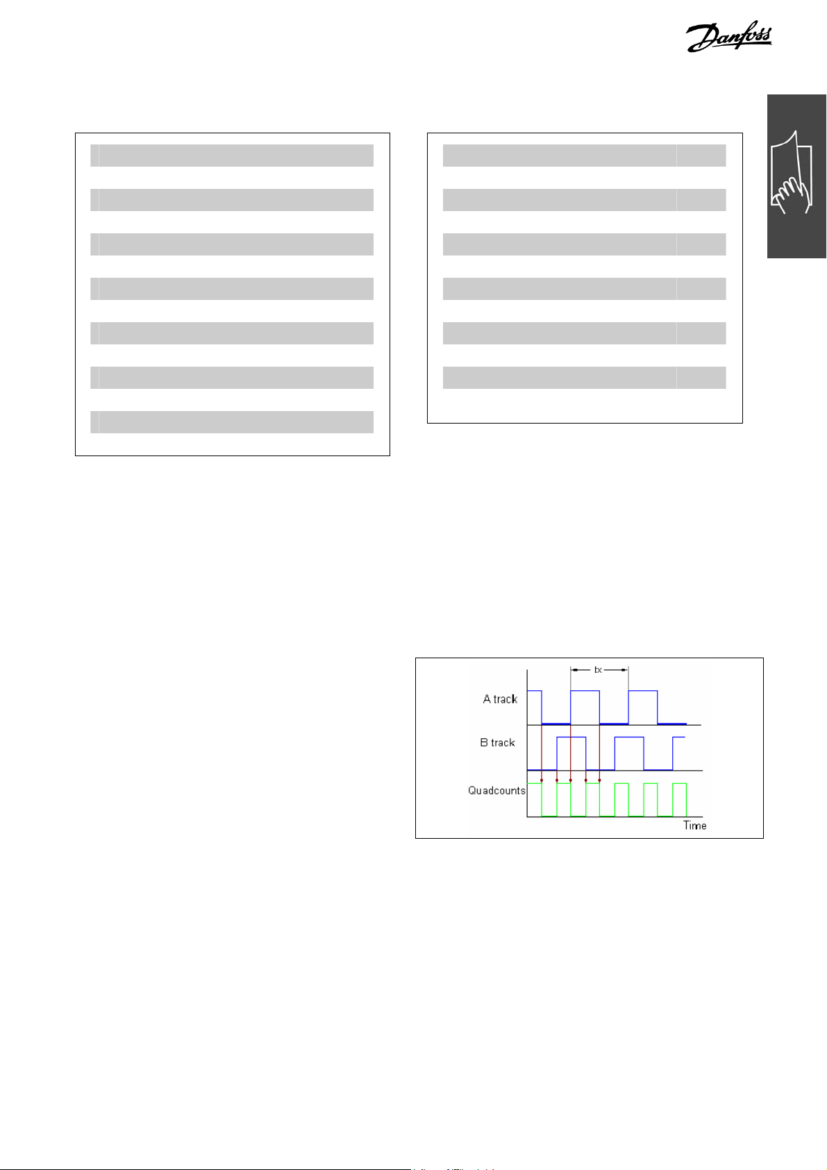
Quad-counts
Incremental encoders: 4 quad-counts correspond to
one sensor unit.
Absolute encoders: 1:1 (1 qc correspond to one
sensor unit).
Through edge detection, a quadrupling of the increments is produced by both tracks (A/B) of the
incremental encoder. This improves the resolution.
Derivation of quad counts
MG.34.R1.02 – VLT
®
is a registered Danfoss trademark 5

MCO 305 Command Reference
__ How to Read this Command Reference __
User Units
The units for the drive or the slave and the master, respectively, can be defined by the user in any way
desired so that the user can work with meaningful measurements.
Starting with MCO 5.00 the factors SYNCFACTM / SYNCFACTS, POSFACT_Z / POSFACT_N are no longer
limited to small values
Internally, it is act as follows: Whenever a value must be multiplied by the gear factor (i.e. master increments per ms), at first it is looked if a multiplication will result in an overflow. If so, a factor (64 bit) is used
which consists of
SYNCFACTS/SYNCFACTM to multiply the delta_master.
If no overflow occurs, first it is multiplied by SYNCFACTS and then divided by SYNCFACTM.
Concerning the error we are dealing with, this means:
Normal case
Multiplying by SYNCFACTS has no error, but dividing by SYNCFACTM means that the result may be wrong by
. That means that (worst case) such an error occurs every ms, i.e. that after 1193 hours (49,71 days)
1/2³²
we made an error of 1 qc (Slave).
Big factors
In that case, the used factor (SYNCFACTS/SYNCFACTM) itself could be wrong by 1/2³² . This means that in
the worst case an error of delta_master * 1/2³²
occurs every ms. Assume that we have an encoder with
1000 counts (4000 qc) per revolution. Assume further, that we drive with 2000 rpm, i.e. we have a velocity
of 133 qc/ms. This means we make an error of 133 * 1/2³² per ms. From this follows that in worst case
(maximum error every ms always in same direction) we could have an error of 1 qc after 9 hours.
This should not be relevant in most applications.
User Units [UU]
All path information in motion commands are made in user units and are converted to quad-counts
internally. These also have an effect on all commands for the positioning: e.g. APOS.
The user can also select meaningful units for the CAM control in order to describe the curve for the master
and the slave, for example 1/100 mm, or 1/10 degrees in applications where a revolution is being observed.
In the CAM control, the maximum run distance of the slave or the slave cycle length are indicated in User
Units UU (qc).
The unit can be standardized with a factor. This factor is a fraction which consists of a numerator and
denominator:
UU UnitUser 1 =
12-32 par.
11-32 par.
Numerator Unit User
Denomintor Unit User
par. 32-12 User Unit Numerator POSFACT_Z
par. 32-11 User Unit Denominator POSFACT_N
Scaling determines how many quad-counts make up a user unit. For example, if it is 50375/1000, then one
UU corresponds to exactly 50.375 qc.
NB!:
When user units are transferred into qc, then they get truncated. When qc are transferred into
user units, then they get rounded.
Master Units [MU]
A factor (fraction) is used for the conversion into qc, as with the user unit:
1033 par.
MU UnitMaster 1
=
−
1133 par.
−
Master Factor ationSynchroniz
Slave Factor ationSynchroniz
par. 33-10 Synchronization Factor Master SYNCFACTM
par. 33-11 Synchronization Factor Slave SYNCFACTS
6 MG.34.R1.02 – VLT
®
is a registered Danfoss trademark

MCO 305 Command Reference
Command Reference
In the following section all commands are listed in alphabetical order and described in detail with syntax
examples as well as short program samples. Please read also the section “Basics” in chapter “How to
Progam” in the MCO 305 Design Guide.
7 MG.34.R1.02 – VLT
®
is a registered Danfoss trademark
MCO 305 Command Reference
__ Command Reference __
ACC
Summary Setting acceleration for motion commands.
Syntax ACC a
Parameter a = acceleration
Description The ACC command defines the acceleration for the next motion command (speed
control, synchronizing or positioning). The value will remain valid until a new
acceleration value is set, using the ACC command. The value is related to the
parameters 32-81 Shortest Ramp and 32-80 Maximum Velocity as well as 32-83
Velocity Resolution.
NB!:
If acceleration has not been defined previous to a motion command, then the
maximum acceleration will be the setting of par. 32-85 Default Acceleration.
NB!:
If the MCO 305 is used to control FC 300, then the ramps should always set via the
option card and not in the FC 300. The FC 300 ramps must always be set to
minimum.
Command Group REL, ABS
Cross Index DEC, VEL, POSA, POSR,
Parameters: 32-81 Shortest Ramp, 32-80 Maximum Velocity, 32-83 Velocity
Resolution
Syntax Example ACC 10 /* Acceleration 10 */
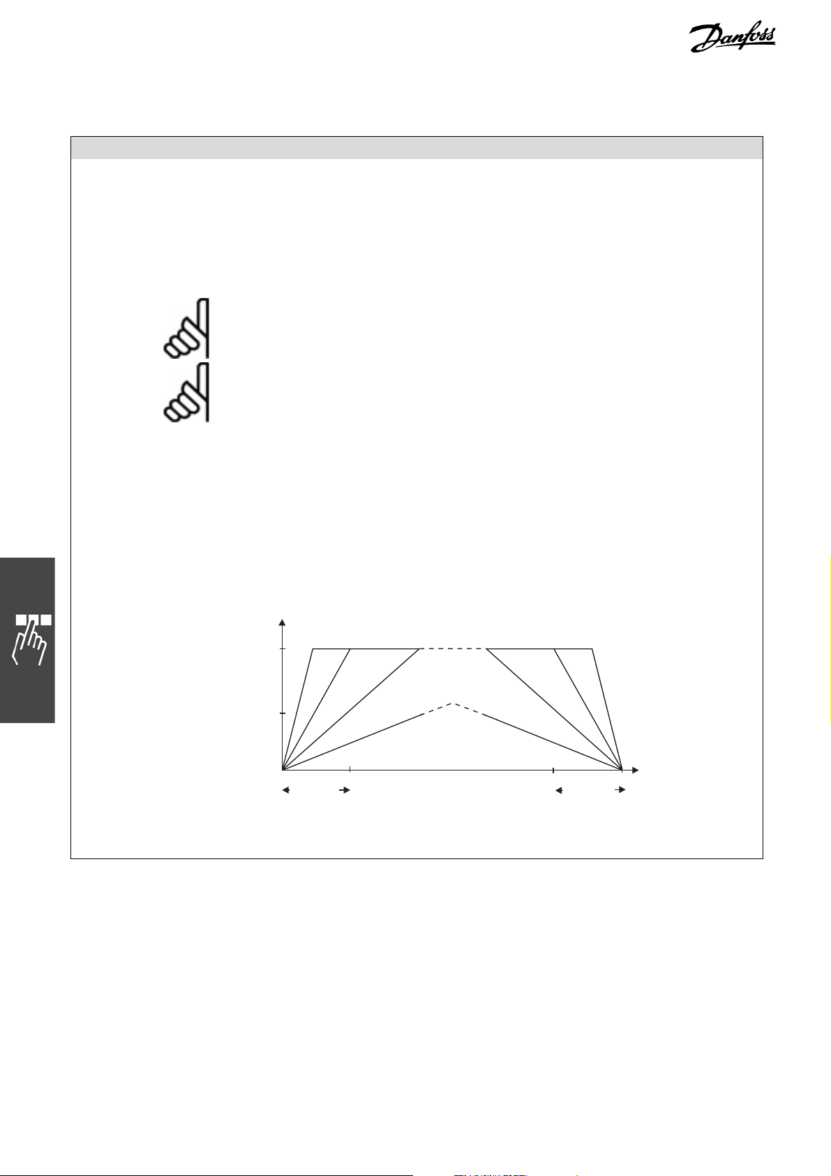
Example minimum acceleration time: 1000 ms
maximum velocity: 1500 RPM (25 Rev./s)
velocity resolution: 100
Velocity
[RPM]
VELMAX
par. 32-80
175MD450
RAMPMIN
par. 32-81
Program Sample ACC_01.M
8 MG.34.R1.02 – VLT
RAMPMIN
par. 32-81
®
is a registered Danfoss trademark
t
[ms]

MCO 305 Command Reference
APOS
Summary Reads actual position
Syntax res = APOS
Return Value res = absolute actual position related to the actual zero point
All path information in motion commands are made in user units and are converted
to quad-counts internally. (See also Numerator and Denominator, parameters 32-12
and 32-11.)
The user unit (UU) corresponds in standard setting to the number of Quad counts.
Parameter ==
Description The APOS command can query the absolute position of the axis related to the
actual zero point.
If a temporary zero point which has been set via SETORIGIN exists, then the
position value is relative to this zero point.
NB!:
The read out using APOS may or may not be equal to the target position or
commanded position. The error or deviation may be due to the mechanics involved
and truncated decimal values in the User Units.
APOS is affected by the parameters 32-12 and 32-11, and by commands
SETORIGIN p, DEFORIGIN.
Example:
POSA 2000
PRINT "Actual Position Reached", APOS
Output:
Actual Position Reached 2000
(depending on PID settings a small deviation
may occur)
Example with SETORIGIN
SETORIGIN 2000
POSA 2000
PRINT "Actual Position”, APOS
Output:
Actual Position 2000
__ Command Reference __
12-32 par.
11-32 par.
Numerator Unit User
Denomintor Unit User
1
Initial
0
After execution
2000
After Positioning
0
Initial
0
Program on execution sets the original 2000 qc as the origin and then moves the
drive by 2000 qc more for positioning command.
Command Group SYS
Cross Index CPOS, DEFORIGIN, SETORIGIN, POSA, POSR,
Parameters: 32-12 User Unit Numerator, 32-11 User Unit Denominator
Syntax Example PRINT APOS /* display the actual position of axis on the PC */
Program Sample APOS_01.M, GOSUB_01.M, MOTOR_01.M
MG.34.R1.02 – VLT
®
is a registered Danfoss trademark 9

MCO 305 Command Reference
APOSDIFF
Summary Overflow handling of incremental encoders in applications.
Syntax res = APOSDIFF oldpos
Return Value oldpos = APOS at a previous time
Description Returns difference between APOS and oldpos (res = APOS – oldpos) in UU.
This command simplifies overflow handling of incremental encoders in applications.
If, for example, the user stores an actual position in his program and wants to
calculate the difference at a later time, then he normally has to account for overflow
of the position. Instead this command can be used; see below.
Internally those routines look if the difference is bigger than POS_LIMIT
(0x3FFFFFFF). If so then it is assumed that an overflow happened and it is handled
correctly.
NB!:
This will not solve the problem of overflowing if the application uses user units.
Portability
Command Group SYS
Cross Index APOS
Syntax Example oldpos = APOS
Command is available starting with MCO 5.00
…..
diff = APOSDIFF oldpos
// this function returns the difference between APOS and oldpos in user units
// handling an overflow if necessary (diff = APOS – oldpos)
__ Command Reference __
AVEL
Summary Queries actual velocity of axis.
Syntax res = AVEL
Return Value res = actual velocity of axis in UU/s, the value is signed
Description This function returns the actual velocity of the axis in User Units per second. The
accuracy of the values depends on the duration of the measurement (averaging).
The standard setting is 20 ms, but this can be changed by the user with the
_GETVEL command. It is sufficient to call up the command once in order to work
with another measuring period from then on. Thus, the command:
var = _GETVEL 100
sets the duration of the measurement to 100 ms, so that you have a considerably
better resolution of the speed with AVEL and MAVEL, however, in condertrast, quick
changes are reported with a delay of a maximum of 100 ms.
Command Group SYS
Cross Index MAVEL, APOS, _GETVEL
Syntax Example PRINT AVEL /* queries actual velocity of axis and display on the PC */
10 MG.34.R1.02 – VLT
®
is a registered Danfoss trademark

MCO 305 Command Reference
__ Command Reference __
AXEND
Summary AXEND reads info on status of program execution.
Syntax res = AXEND
Return Value res = axis status with the following meaning:
Value Bit
128 7 1 = Motor is reset, i.e. it is ready to start and is controlling
again, e.g. after ERRCLR, MOTOR STOP, MOTOR ON
64 6 1 = axis controller is OFF, motor is off
4 - 5 not in use
8 3 1 = motor is at STOP status
4 Bit 2 1 = speed mode is active
2 Bit 1 1 = positioning procedure is active
1 Bit 0 1 = target position reached; motor is not in motion
Description The AXEND command gives the actual status of the axis or the status of the
program execution.
This means for example that you can enquire when the “position is reached” and a
positioning command (POSA, POSR) has actually been completed. When Bit 1 is set
at [0] the positioning process is complete and the position reached.
If, however, the positioning command has been interrupted with MOTOR STOP and
continued later with CONTINUE, then the following bits would be set at [1]:
the Bit 0 for “motor is at a standstill”
the Bit 1 for “positioning process active”
the Bit 3 for “motor is at STOP status”
the Bit 6 for “axis controller switched off”
The AXEND command is especially suitable for determining whether or not a
movement in the NOWAIT ON condition is terminated.
Command Group SYS
Cross Index WAITAX, STAT, NOWAIT
Syntax Example NOWAIT ON // do not wait until position is reached
POSA 100000
WHILE (AXEND&2) DO
// as long as the positioning process is active, repeat loop
IF IN1 THEN // if input 01 is set
VEL 100 // increase velocity
POSA 100000
WAIT IN1 OFF // wait until input (key) is off
ENDIF
ENDWHILE // position reached
Syntax Example IF (AXEND&64) THEN
OUT 1 1 // set output 01, when axis controller is switched off
ELSE
OUT 1 0
ENDIF
Program Sample AXEND_01.M
MG.34.R1.02 – VLT
®
is a registered Danfoss trademark 11

MCO 305 Command Reference
CANDEL
Summary Deletes all or single CAN objects.
Syntax CANDEL objno
Parameter objno = object number, which is returned during the definition of the object
= –1 deletes all objects (except the standard objects)
Description With the CANDEL command CAN objects which were previously created with
DEFCANIN or DEFCANOUT can be deleted.
Standard objects, for the buffered input/output (OUTMSG or INMSG) cannot be
deleted with this command. These cannot be created during initialization.
Portability Command is available starting with MCO 5.00.
Command Group CAN
Syntax Example CANDEL –1 /* all CAN objects are deleted */
CANIN
Summary Reads an object via the CAN bus.
Syntax status = CANIN objno time-out control varhi varlo
Parameter objno = object number which is returned during the definition of the object.
time-out = –1 does not wait for data
control = 0 Checks whether the new data has arrived. The new data is
= 1 Sends a remote frame and waits for data in dependence on
varhi = Bytes 0 to 3 of the CAN object data
varlo = Bytes 4 to 7 of the CAN object data
Return Value Status = –1 no data has arrived
= 0 o.k.
Description
The CANIN command copies the data (if present) of the CAN object 'objno' to the
variables 'varhi' and 'varlo'. If 'control = 1', then the data is requested first.
It is possible to gather all Transmit-PDOs of digital input modules or CAN-Drive
status by using only one CAN telegram. This feature is restricted to the Master-bus
This feature must use the CAN-Object 15 internally which reduces the number of
usable CAN objects on the master bus by 1.
To enable this feature, the command CANINI 999 must be used
This command enables reception of TxPDOs by interrupt and stores every received
PDO in a buffer with a depth of 1. This works for all IDs from 1 to 127. That means
if any IO-module in that range sends a TxPDO it is captured and stored it in the
buffer. The next TxPDO from the same module of course overwrites the first one. To
read out of the buffer, the following command can be used:
result = CANIN (id * 100) timeout 0 hi lo
This command returns -1 if no new information was in the buffer, otherwise it
returns 0. You can use the timeout normally (-1 does not wait, 0 waits for ever for
new information, n waits n ms).
__ Command Reference __
= 0 waits until data arrives
> 0 waits for the data in time-out [ms]
subsequently copied to the variables.
time-out
.
12 MG.34.R1.02 – VLT
®
is a registered Danfoss trademark

MCO 305 Command Reference
__ Command Reference __
The result is returned in hi and lo, but we already arrange byte ordering so that
they can be used as if you read them with PDO[]. That means if lo contains a 32-bit
number then you can use it right away without reordering the bytes.
Whenever you use a new CANINI command or you start a new program, this
feature is disabled.
Using this feature of course loads the processor if there is heavy PDO traffic on the
BUS.
NB!:
It is not
the same bus. This may lead to unwanted results. If you use, for example, a
CANopen digital I/O module with ID 3 on the master bus with an IN (3*256+1) or
with CANINI 3 999, then this will result in a situation where the IN command will
work but you would not get the PDOs with the above described CANIN command.
This is because two CAN objects will exist with the same ID. In that case, the
processor only serves the first one. As mentioned above, we use object 15 for
reception of all PDOs, which is the last one.
Portability
Optional command and extended commands CANINI and CANIN to use only one
CAN telegram are available starting with MCO>=5.00.
Command Group CAN
Cross Index CANOUT, CANDEL, DEFCANOUT, DEFCANIN, CANINI
Syntax Example MSG = 0
temp = 0 /* Define variables */
rx1 = DEFCANIN 42 8 /* a RX object is created */
STAT = CANIN rx1 1000 0 MSG temp /* wait 1s for data */
Program Sample CAN_sample.M, CANIN.M
recommend this feature be used together with other CAN IO commands on
MG.34.R1.02 – VLT
®
is a registered Danfoss trademark 13

MCO 305 Command Reference
CANINI
Summary Initializes the necessary objects (PDOs) for data exchange of CANopen nodes, or
enables extended CANINI, CANIN function.
Syntax CANINI no, no, no, …,
CANINI 999
CANINI no, no, 999, no
is also possible, but only in the same command. The next new command would
delete the previous parameters.
Parameter no = guard * (busoffset * 1000 + id)
guard = –1, +1 (without / with guarding)
busoffset = 100000 , 0 (slave bus, master bus)
Samples for CANINI values:
Description The CANINI command establishes contact with CAN devices and creates permanent
Every new CANINI command reinitializes all objects which were assigned before
Portability Command is available starting with MCO 5.00.
1…127 CAN I/O with bus ID 1…127 with guarding
-1…–127 CAN I/O with bus ID 1…127 without guarding
corresponding CAN objects in order to be able to communicate (using PDO) with
these devices. The advantage is that these input modules can also be used for
interrupt functions without permanent bus load due to status polling.
If you do not need any interrupts, then you can accelerate the processing of the IN
and INB commands with CANINI, since the corresponding devices send these
information autonomously every time a change of state happens.
It is strongly recommended to “guard” (i.e. CANINI > 0) any CAN devices, which
are initialized using CANINI. That is the only way to make sure, that the device is
still present and takes part in bus communication. If one device is no longer
present, then an error 188 is triggered by the missing feedback of the GUARD
object. An error routine, defined with ON ERROR can react to such an error state.
When CANINI is executed for drives, the corresponding PDO is created and also the
SYNC object if necessary. If guarding is started, a guarding telegram is sent every
20 ms to one device. If for example 4 devices are guarded, it takes 80 ms to check
each device once. No response within 100 ms indicates an error 188 (guarding
error).
A maximum of 16 modules can be stored internally.
with CANINI, i.e. guarding (GUARD) is stopped and also SYNC telegrams. This is
not true, if there are permanent objects from par. 32-00 or 32-30 Incremental
Signal Type. These objects will still remain, like the internal automatically created
PDOs corresponding to the definition of parameters 32-00 and 32-30 Incremental
Signal Type.
The CANINI command starts all modules synchronously, i.e. for every module a
NMT0 message is sent to set the module on the status “operational”.
If a CANINI fails, it is possible to read the SYSVAR 67 [0x01220244] GuardErrorId
to find out which id caused the problem.
__ Command Reference __
Deletes any objects, which were formerly assigned using the
0
CANINI command.
enables reception of all TPDO1s (0x181-0x1FF) by interrupt and
999
stores every received PDO in a buffer with a depth of 1.
14 MG.34.R1.02 – VLT
®
is a registered Danfoss trademark

MCO 305 Command Reference
NB!:
If the CANINI command is used on controls with multiple separated CAN bus
circuits, GUARD and SYNC functionality is only supported on the so-called slave
bus.
Command Group CAN
Cross Index IN, INAD, INB, OUT, OUTB, OUTDA,
par. 32-00 and par. 32-00 Incremental Signal Types
Syntax Example CANINI 1,2,3,4 /* Initialize the CAN modules with pre-set node number */
Program Sample CAN_sample.M
CANOUT
Summary Sends message with an internal number.
Syntax CANOUT no valhi vallo
Parameter valhi Bytes 0 to 3 of the CAN object data
vallo Bytes 4 to 7 of the CAN object data
Description A CAN message is sent with this command from a sending object defined by
DEFCANOUT. The values hi and lo are 4 bytes long
Portability Command is available starting with MCO 5.00.
Command Group CAN
Cross Index CANIN, CANDEL, DEFCANIN, DEFCANOUT
Syntax Example valhi = 21
vallo = 41
tx1 = DEFCANOUT 500 8
/* TX object is defined with Id=500 and data length = 8 bytes */
CANOUT tx1 valhi vallo /* a CAN message is sent */
Program Sample CANOUT.M
__ Command Reference __
MG.34.R1.02 – VLT
®
is a registered Danfoss trademark 15

MCO 305 Command Reference
COMOPTGET
Summary Reads a Communication option telegram
Syntax COMOPTGE T n o a r ray
Parameter array = the name of an array which must be at least the size of no
no = number of words to be read
Description COMOPTGET reads from the Communication option buffer the no words and writes
them in the array ‘array’, starting with the first element.
Portability Option
Communication
Option Function
Control data: The function of Control word (CTW) and Main Reference (MRV) depends on the
Process data: PCD’s 1 – 4 of PPO type 2/ 4 and PCD’s 1 – 8 of PPO type 5 are not assigned a
Command Group Communication option
Cross Index COMOPTSEND
Program Sample COM_OPT
Parameters: Read and write parameters are not affected by the option board.
NB!:
The parameters 9-15 and 9-16 have additionally to be set with the correct values.
setting of par. 33-82 Drive Status Monitoring; Status words (STW) and Main actual
value (MAV) is always active:
Parameter 33-82 Parameter 33-82
“Enable MCO 305” “Disable MCO 305”
CTW/MRV Disabled Active
STW/MAV Active Active
parameter number by parameters 9-15 and 9-16 but are used as a free data area
which can be used in a APOSS program.
The command COMOPTGET is copying the data received on the communication
option into an array, where each array element contains one data word (16 bit).
The command COMOPTSEND is copying data from an array, where each array
element contains one data work (16 bit) into the send buffer on the communication
option, from where it is send via the network to the master.
__ Command Reference __
COMOPTSEND
Summary Writes in the Communication option buffer
Syntax COMOPTSEND no array
Parameter array = the name of an array which must be at least the size of ‘no’
no = number of words to be sent
Description COMOPTSEND writes in the Communication option buffer. In doing so the first ‘no’
values are sent from the ‘array’.
Portability With built-in Communication option.
Communication
See command COMOPTGET
Option Function
Command Group Communication option
Cross Index COMOPTGET
Program Sample COM_OPT
16 MG.34.R1.02 – VLT
®
is a registered Danfoss trademark

MCO 305 Command Reference
__ Command Reference __
CONTINUE
Summary Continues positioning from point of interrupted motion
Syntax CONTINUE
Description By using CONTINUE, positioning and speed motion commands which have been
aborted via the MOTOR STOP command or an error condition or stopped via MOTOR
OFF can be resumed.
The CONTINUE command can be used especially in an error subroutine in
connection with the ERRCLR command, to enable the correct continuation of a
motion procedure following an error abort.
NB!:
However CONTINUE does not continue interrupted synchronization commands.
Command Group CON
Cross Index MOTOR STOP, ERRCLR, ON ERROR GOSUB
Syntax Example CONTINUE /* continue interrupted motion procedure */
Program Sample MSTOP_01.M
CPOS
Summary Reads the actual command position of an axis
Syntax res = CPOS
Return Value res = Absolute commanded position in User Units (UU) related to the actual zero
point
Description The CPOS command queries the actual commanded position of the axis related to
the actual zero point. The commanded position is understood to be the temporary
set position which is re-calculated every millisecond by the positioning control
during a positioning procedure or a movement in rotation mode.
The command position can be queried independently of the operating condition
(position control during standstill, positioning process, speed control or
synchronization).
NB!:
If a set and active temporary zero point (set via SETORIGIN) exists, then the
position value is relative to this zero point.
Command Group SYS
Cross Index APOS, DEFORIGIN, SETORIGIN, POSA, POSR,
Parameters: 32-12 User Unit Numerator, 32-11 User Unit Denominator
Syntax Example PRINT CPOS /* actual command position of axis */
Program Sample CPOS_01.M, GOSUB_01.M
MG.34.R1.02 – VLT
®
is a registered Danfoss trademark 17

MCO 305 Command Reference
CPOSDIFF
Summary Overflow handling of incremental encoders in applications.
Syntax res = CPOSDIFF oldpos
Parameter oldpos = CPOS at a previous time
Return Value Returns difference between CPOS and oldpos (res = CPOS – oldpos) in UU.
Description This command simplifies overflow handling of incremental encoders in applications.
If, for example, the user stores an actual position in his program and wants to
calculate the difference at a later time, then he normally has to account for overflow of the position. Instead this command can be used; see below.
Internally those routines look if the difference is bigger than POS_LIMIT
(0x3FFFFFFF). If so then it is assumed that an overflow happened and it is handled
correctly.
This will not solve the problem of overflowing if the application uses user units.
Portability Command is available starting with MCO 5.00.
Command Group SYS
Cross Index CPOS
Syntax Example oldpos = CPOS
…..
diff = CPOSDIFF x(1) oldpos
// this function returns the difference between CPOS and oldpos in user units
// handling an overflow if necessary (diff = CPOS – oldpos)
__ Command Reference __
CSTART
Summary Starts the speed mode
Syntax CSTART
Description The CSTART command is starting the drive in speed control mode.
Acceleration/deceleration, as well as the speed should be set via the ACC, DEC and
CVEL commands prior to starting.
CSTART does not contain the command MOTOR ON which turns on the motor
control. When using CSTART an explicit calling up of MOTOR ON is necessary after
previous use of MOTOR OFF.
NB!:
If no speed value has been defined via CVEL before the beginning of CSTART, then
the default velocity 0 is used – this means that the motor will not rotate, but the
PID controller is active.
All CVEL commands following the start of speed mode will be carried out
immediately, i.e. a corresponding speed change will take place immediately, with
the defined acceleration or deceleration (ACC/DEC).
Command Group ROT
Cross Index ACC, DEC, CVEL, CSTOP
Syntax Example CSTART /* rpm mode start */
Program Sample CMODE_01.M
18 MG.34.R1.02 – VLT
®
is a registered Danfoss trademark

MCO 305 Command Reference
__ Command Reference __
CSTOP
Summary Stops the drive in speed mode
Syntax CSTOP
Description Via the CSTOP command, the speed mode is terminated and the positioning mode
is started, whereby a still rotating axis is stopped the deceleration defined with DEC
and the motor is held in the stop position.
NB!:
A CSTOP command carried out in the positioning mode can also cause an abrupt
termination of the positioning procedure.
Command Group ROT
Cross Index ACC, DEC, CVEL, CSTART
Syntax Example CSTOP /* rpm mode stop */
Program Sample CMODE_01.M
MG.34.R1.02 – VLT
®
is a registered Danfoss trademark 19
MCO 305 Command Reference
CURVEPOS
Summary Retrieve slave curve position that corresponds to the current master position of
the curve.
Syntax res = CURVEPOS
Return Value res = Slave position in CAM units (UU) absolute to the current zero point.
Description CURVEPOS returns the slave value which corresponds to the actual curve master
position.
The position can be retrieved independently of the operating status (position
control at standstill, positioning procedure, velocity control or synchronization).
CMASTERCPOS (SYSVAR) and CURVEPOS are now updated even if SYNCC is no
longer active. The update of these values starts after a SETCURVE command (if
par. 33-23 Start Behavior for Sync is < 2000) or after SYNCC and the first master
marker (if par. 33-23 = 2000).
After the SYNCC command is stopped, we continue to update these values if Start
Behavior for Sync. < 2000.
NB!:
The position is only defined if a SETCURVE has been set before.
__ Command Reference __
NB!:
If a temporary zero point exists which has been set with SETORIGIN and is active,
the position value will refer to this zero point.
NB!:
DEFMCPOS and DEFMORIGIN can still modify this position.
Command Group CAM
Cross Index APOS, DEFORIGIN, SETORIGIN, POSA, POSR, DEFMCPOS,
Parameters: 33-10 Syncfactor Master, 33-11 Syncfactor Slave
Syntax Example PRINT CURVEPOS // print actual slave position of the curve
Sample
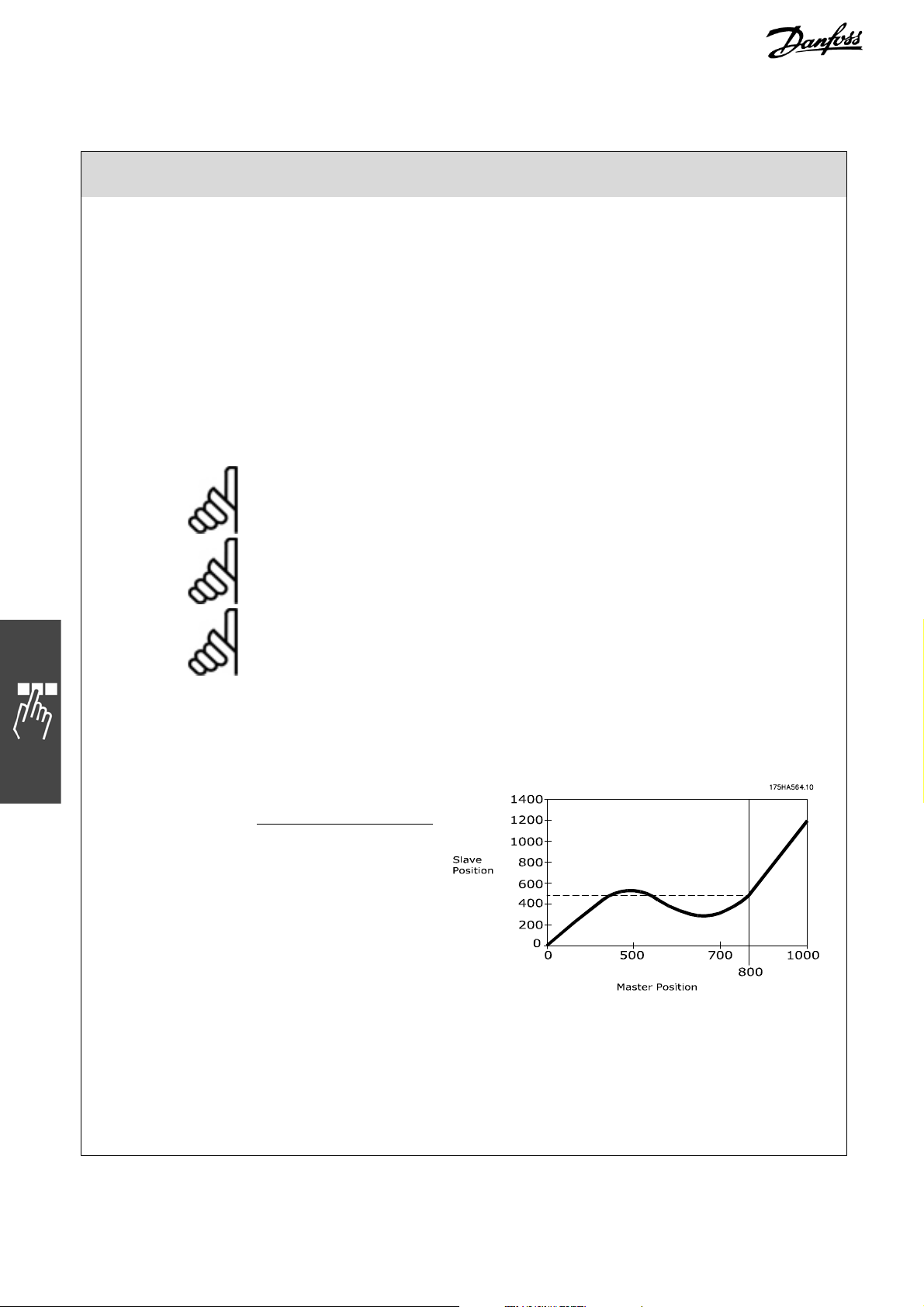
Fix points of a curve:
Master Slave
0
500
700
1000
0
500
300
1200
Say the current master position is 800. Then the CURVEPOS returns the corres-
ponding slave position of 450.
Case 1: Current Master Position is 800 and current slave position is 200.
CURVEPOS will return the value 450.
Case 2: Current Master Position is 800 and current slave position is 700.
CURVEPOS will return the value 450.
Hence CURVEPOS is independent of the slave position.
20 MG.34.R1.02 – VLT
®
is a registered Danfoss trademark

MCO 305 Command Reference
CVEL
Summary sets velocity for speed controlled motor movements
Syntax CVEL v
Parameter v = velocity value (negative value for reversing)
__ Command Reference __
Description The velocity for the next speed controlled motor movement is set with the CVEL
command. The value remains valid until a further CVEL sets a new velocity.
The velocity value to be given will be related to the parameters 32-80 Maximum
Velocity and 32-83 Velocity Resolution.
NB!:
CVEL commands which take place after CSTART will be carried out immediately i.e.
the velocity will be adapted via the ACC/DEC set acceleration or deceleration to the
new value of CVEL.
If a velocity has not been defined before the start of speed control mode (CSTART),
then the default velocity is 0, i.e. the motor will not turn, and a velocity input via
CVEL will start the movement in speed control mode.
Command Group ROT
Cross Index ACC, DEC, CSTART, CSTOP,
Parameter: 32-80 Maximum Velocity
Syntax Example CVEL 100
Program Sample CMODE_01.M
DEC
*V [RPM] Velocity Command =
Velocity Maximum 80-32 par.
Resolution Velocity 83-32 par.
Summary sets deceleration
Syntax DEC a
Parameter a = deceleration
Description The DEC command defines the deceleration for the next motion command (speed
control synchronization or positioning). This value will remain valid until a new
deceleration value is set with another DEC command. The value is related to the
parameters 32-81 Shortest Ramp and 32-80 Maximum Velocity as well as 32-83
Velocity Resolution.
NB!:
If deceleration is not defined previous to the positioning command then deceleration will be the setting of parameter 32-85 Default Acceleration.
NB!:
If you work with the MCO 305 then you should always set the ramps via the option
card and not in the FC 300. The FC ramps must always be set to minimum.
Command Group REL, ABS
Cross Index ACC, Parameters: 32-81 Shortest Ramp, 32-80 Maximum Velocity, 32-83 Velocity
Resolution
Syntax Example ACC 50 /* acceleration: 50, while braking 10 */
DEC 10
Example minimum acceleration time: 1000 ms
maximum velocity: 1500 RPM
velocity resolution: 100
MG.34.R1.02 – VLT
®
is a registered Danfoss trademark 21

MCO 305 Command Reference
__ Command Reference __
DEFCANIN
Summary Defines a receive object.
Syntax objno = DEFCANIN id dlen
Parameter id = CAN-identification number
dlen = data length of the object in bytes (max. 8 bytes)
Return Value objno
A positive value means that the object was successfully created. This value is an
internal number of the object and is used by other APOSS-CAN commands. A
negative value means an error has occurred.
Description This command defines an incoming communication object in the CAN-Controller.
This command can also be used with the offset for the slave bus (telegram ID
100000).
These objects can now be deleted one by one via the command CANDEL objno,
where objno is the number returned by DEFCANIN or DEFCANOUT.
Portability Command is available starting with MCO 5.00.
Command Group CAN
Program Sample var1 = 0 /* declare variables */
var2 = 0
rx1= DEFCANIN 500 8
/* RX object with Id=500 and data length=8 bytes is defined */
CANIN rx1 0 0 var1 var /* a CAN message is read */
DEFCANOUT
Summary Defines a transmit object in the CAN controller.
Syntax objno = DEFCANOUT id dlen
Parameter id = CAN-identification number
dlen = data length of the object in bytes (max. 8 bytes)
Return Value objno
A positive value means that an object was successfully created. This value is an
internal number of the object and is used by other APOSS-CAN commands. A
negative value indicates an error.
Description This command defines an object in the CAN-Controller. This object is an outgoing
object with a length of n bytes and the CAN identification of (id). Thus, objno is an
internal number of the object ld and is used by the CANOUT command.
This command can also be used with the offset for the slave bus (telegram ID 100000).
So it is possible to define messages for slave and master bus. These objects can
now be deleted one by one via the command CANDEL objno, where objno is the
number returned by DEFCANIN or DEFCANOUT.
Portability Command is available starting with MCO 5.00.
Command Group CAN
Cross Index DEFCANIN, CANOUT, CANIN
Syntax Example no = DEFCANOUT 500 8
/* defines an object with ld=500 and length 8 bytes */
/* the function returns a 1 */
/* a message with ld=500 and a length of 8 bytes can now be sent */
/* with the command CANOUT 1 value1 value2 */
no = DEFCANOUT id len
22 MG.34.R1.02 – VLT
®
is a registered Danfoss trademark
MCO 305 Command Reference
__ Command Reference __
DEFCORIGIN
Summary Sets the command position as zero point.
Syntax DEFCORIGIN
Description DEFCORIGIN sets the command position as zero point. All absolute positioning
commands (POSA etc.) refers to this zero point from now on.
In doing so CPOS is set to zero and APOS is set in that way, that the difference is
remained.
Portability Command is available starting with MCO 5.00.
Command Group INI
Cross Index POSA, DEFORIGIN, CPOS
Syntax Example POSA 80000 /* absolute positioning */
DEFCORIGIN X(1) /* define command position as zero point */
DEFMCPOS
Summary Define initial position of the master
Syntax DEFMCPOS p
Parameter p = position in Master Units (MU)
Description DEFMCPOS defines the initial position of the master (in MU) in the CAM-Mode and
thus the point where the curve begins as soon as the master pulses are being
counted.
Command Group CAM
Cross Index DEFMORIGIN, SETMORIGIN, SYNCC,
Parameter: par. 33-23 Start Behavior for Sync.
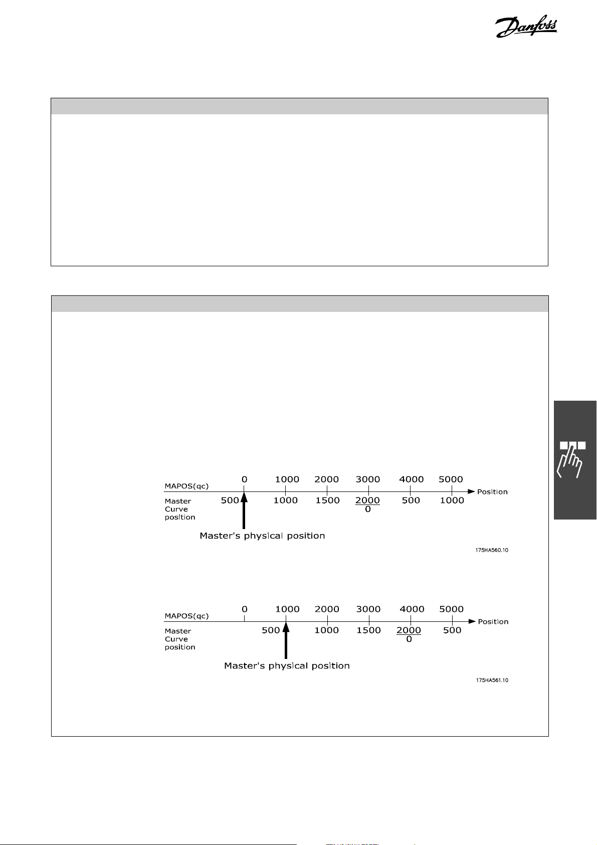
Syntax Example DEFMCPOS 1000 // Set internal MU counter to 1000
Sample DEFMCPOS positions Master’s current physical position to the master curve position
indicated irrespective of what the MAPOS is.
When a DEFMCPOS 500 is issued, master’s physical position is made as the position
500 of the curve.
When a DEFMCPOS 500 is issued, master’s physical position is made as the position
500 of the curve.
MG.34.R1.02 – VLT
®
is a registered Danfoss trademark 23

MCO 305 Command Reference
__ Command Reference __
DEFMORIGIN
Summary Set the current master position as the zero point for the master.
Syntax DEFMORIGIN
Description DEFMORIGIN defines the current master position as the zero point for the master.
The master position (MAPOS) refers to this zero point until a redefinition takes
place using DEFMORIGIN or SETMORIGIN.
NB!:
The command DEFMORIGIN can not be used with absolute encoders (see par. 3230 Incremental Signal Type).
Command Group INI
Cross Index MAPOS, SETMORIGIN
Syntax Example DEFMORIGIN /* Set current position as the zero point for the master */
DEFORIGIN
Summary Sets the current position as zero point
Syntax DEFORIGIN
Description With the DEFORIGIN command the current position is set as the zero point. All
absolute positioning commands (POSA) then refer to this zero point.
The actual position reached in a positioning command is the Target position plus
some error which is not compensated automatically while using a DEFORIGIN.
NB!:
The command DEFMORIGIN can not be used with absolute encoders (see par. 3200 Incremental Signal Type).
Command Group INI
Cross Index POSA
Syntax Example POSA 80000 /* Absolute positioning */
DEFORIGIN /* define actual position as zero point */
Sample POSA 2000
PRINT "Position before new origin", APOS
DEFORIGIN
PRINT "Position after defining new origin",
APOS
Output
Position before new origin 2000,
Position after defining new origin 0
Program Sample DORIG_01.M, ORIG_01.M
Initial
0
After executio n
0
(after DEFORIGIN)
24 MG.34.R1.02 – VLT
®
is a registered Danfoss trademark

MCO 305 Command Reference
DEFSYNCORIGIN
Summary Defines master-slave relation for the next SYNCP or SYNCM command, or
defines the start values for standard curves with SYNCC command.
Syntax DEFSYNCORIGIN mcpos spos
Parameter mcpos = master reference position in qc, or
spos = slave reference position, or
spos < SlaveCurveLenght = slave curve position
spos > SlaveCurveLength = the actual curve position has to be seen as the
Description This command defines how much distance ahead or behind should the slave be in
relation to the master position. It allows defining the relation between master and
slave for the next SYNCP or SYNCM command. It sets the internal slave command
position (Mpcmd) to the slave value.
The master value is used for an internal MOVESYNCORIGIN. For that reason, a
MOVESYNCORIGN will be overwritten by this command. Both actions are done at
the moment, when the SYNC command is activated. So it is guaranteed, that
master and slave will be synchronized at the above master-slave position.
With SYNCC the DEFSYNCORIGIN can be used to define the start values for
standard curves as follows:
Here, mcpos tells the controller that the actual master position (MAPOS)
corresponds to a master curve position of mcpos.
spos has two different meanings:
spos < SlaveCurveLenght = defines the actual position of the slave as the slave
spos > Slave CurveLength = the actual curve position has to be seen as the correct
Example: Assuming that the curve is a straight line going from 0,0 to 2000,4000 in
terms of (master,slave).
Further assuming that the slave is at a position of 11000 qc and that the master has
an actual position of 15000 qc. To make it simple, let us assume that the gear
factors are 1 : 1.
If now a SETCURVE is done without any further commands, then the following would
happen. The controller tries to find out where the slave is located within a curve.
Therefore, it calculates the remainder of 11000 / 4000 which is 3000 and the
remainder of 15000 / 2000 which is 1000. That means the result would be that the
actual MCPOS (master curvepos) is 1000. So the corresponding slave curve position
should be 2000. But at the moment the slave is at a curve position of 3000 instead.
(The csstart position is the start position of the last curve, which would be 8000 in
our case). If this curve is started, the slave would try correct the position and move
to 2000.
If now the following command is used
DEFSYNCORIGIN 500 100000
the following will happen:
__ Command Reference __
master curve position in qc
correct position within the curve corresponding to the
master position mcpos
curve position spos.
position within the curve corresponding to the master
position mcpos (spos itself does not have any
meaning, it just has to be greater than slave curve
length).
MG.34.R1.02 – VLT
®
is a registered Danfoss trademark 25
MCO 305 Command Reference
The actual master position is defined as the master curve position of 500.
And because 100000 is bigger than the slave curve length of 4000, the actual slave
position (of 11000 qc) equates to the slave curve position belonging to the master
curve position of 500 which is 1000. So csstart will be set to 10000. If now the
curve is started, it will be ok and just follow the curve when the master starts
moving.
DEFSYNCORIGIN in conjunction with CU_GRAD curves (type 3)
In case of a CU_GRAD curve, the DEFSYNCORIGIN can be used to define the
absolute end position of the curve in qc. In that case, the curve is started
immediately and is calculated in such a manner that the end positions will be
reached at the end of the curve.
NB!:
To avoid degenerate polynomials, the distances must be in a correct relation. If you
start with velocity zero and want to end up with a velocity of 1 (slave has same
velocity as master), then the master distance should be less than two times the
slave distance. Otherwise, the polynomial will have extremes within the interval.
This is more difficult to predict in other cases (start velocity not 0 or end velocity not
1). Therefore, you can check the PG_FLAG_CURVE_ERR to see if the last SETCURVE
produced a curve with extremes (see STAT). Then you can read out the SYSVAR
PFG_LASTERROR (see SDO dictionary) to decide what it was.
Portability Starting with MCO 5.00 start values for curves can be defined.
Command Group SYN
Cross Index MOVESYNCORIGIN
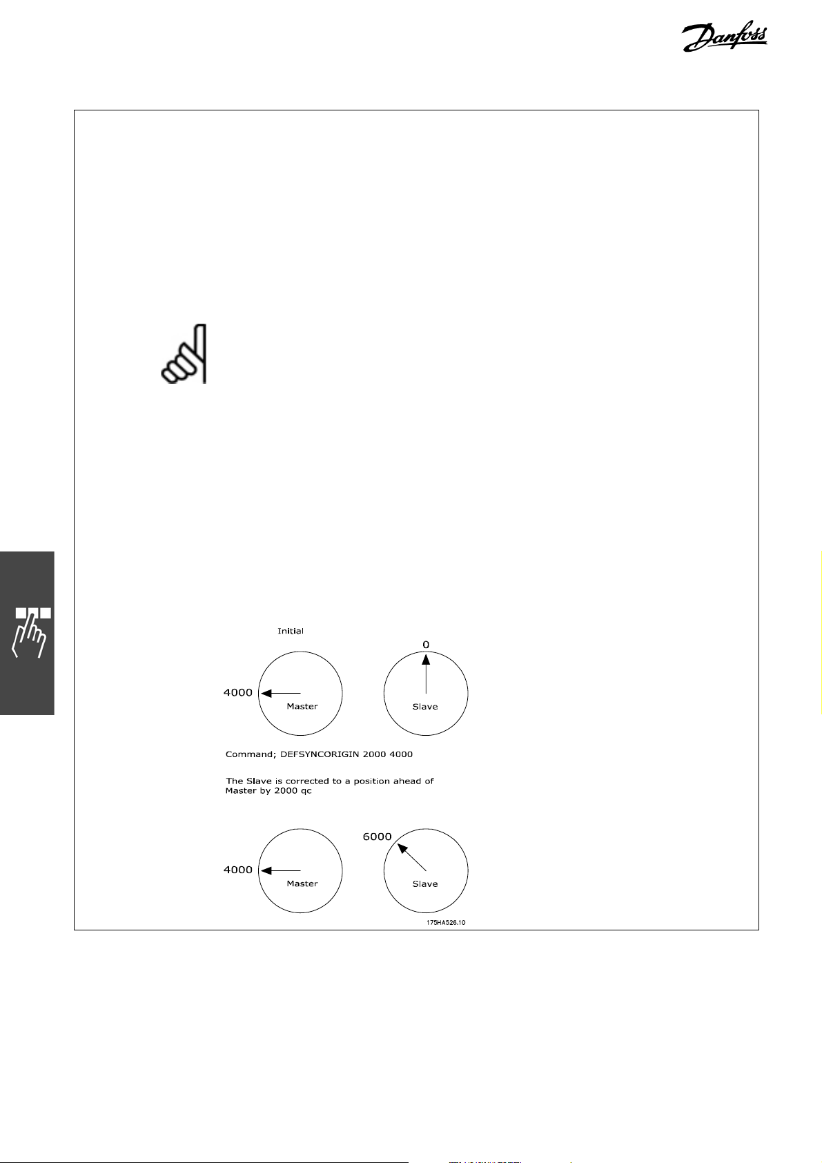
Sample Here when the master is in 2000 qc the slave should be in 4000 qc, i.e., slave
should be ahead of master by 2000 qc.
Also when the master is in 3000 qc the slave should be in 5000 qc.
__ Command Reference __
26 MG.34.R1.02 – VLT
®
is a registered Danfoss trademark

MCO 305 Command Reference
__ Command Reference __
DELAY
Summary Time delay
Syntax DELAY t
Parameter t = time delay in milliseconds (maximum MLONG)
Description The DELAY command leads to a defined program delay. This parameter gives the
delay time in milliseconds.
If an interrupt occurs during the delay time, then following the processing of the
interrupt procedure, the programmed delay will take place after the correct
inclusion of the interrupt time. Thus, the DELAY command gives a constant delay
time, independent of whether various interrupts have to be processed during the
programmed delay time.
If the interrupt requires more processing time than is available for the delay, then
the interruption procedure will be carried out to the end, before the command
following the DELAY instruction is commenced.
Command Group CON
Cross Index WAITT, WAITI, WAITAX
Syntax Example DELAY 1000 /* 1 second delay */
Program Sample DELAY_01.M
DELETE ARRAYS
Summary Delete all arrays in the RAM.
Syntax DELETE ARRAYS
Description With DELETE ARRAYS you can delete all arrays in the RAM without also deleting the
Command Group INI
parameters etc. This command has the same effect as the menu command
Controller → Reset → Arrays.
NB!:
If you then execute a SAVE ARRAYS, the arrays in the EPROM are also overwritten!
NB!:
If DELETE ARRAYS is carried out after a DIM assignment in the program, it is then
no longer possible to access the array elements.
NB!:
If a program contains a DELETE ARRAYS command, there are no more arrays in
the RAM after the program is exited.
MG.34.R1.02 – VLT
®
is a registered Danfoss trademark 27

MCO 305 Command Reference
DIM
Summary Definition of an array
Syntax DIM array [n]
Parameter array = name of the array
n = number of array elements
Description Via a DIM instruction at the commencement of the program, it is possible to
declare one or more arrays (= Variable fields).
Arrays are valid for all programs. If arrays are not yet available in the MCO 305
memory, then the arrays are allocated via the DIM instructions. Arrays which are
already available in the memory are checked to see if their size corresponds to the
current DIM commands. If differences are found, then an error registration is
made. If, additionally to the corresponding arrays, new arrays are declared, then
these must also be added at the end of the DIM command.
Each array element can later be accessed, similar to a variable, calculation results,
characters or other information can be stored.
An array element can be called up via the array name and an index. The indices
are admissible from 1 to the defined size in the DIM allocation.
An essential difference between variables and array elements consists in the fact that
arrays are stored in the non-volatile memory, and their contents are permanent even
when the power supply is switched off – insofar as it is saved with SAVEPROM or SAVE
ARRAYS.
In contrast to variables, arrays have a validity not only for one, but for all
programs in the VLT unit flow. The only condition necessary is that the arrays must
be accessible via a DIM command in the desired program which enables a data
exchange between several programs. It is of no importance whether or not the
array is identified with the same name in all the programs. What is important is the
order of the array definitions. This means, for example, that the first defined array
in all programs always refers to the first stored array in the memory, independent
of the array name.
NB!:
The DIM command must be the first instruction in a program, and must appear
before the subroutines. Indices from 1 to the defined size of the array are
permissible.
The array content will not be lost, even following switching off the power supply.
A defined array size is v alid for all pr ogr ams, and cannot be altered. Only the order of
the array definitions (not the names) det ermines which of the data- fields will be
accessed.
Array definitions can only be canceled via erasure of the entire memory.
Command Group CON
Syntax Example DIM xpos[100], ypos[100]
/* define array XPOS and YPOS each with 100 elements */
Program Sample DIM_01.M
__ Command Reference __
28 MG.34.R1.02 – VLT
®
is a registered Danfoss trademark

MCO 305 Command Reference
DISABLE … interrupts
Summary Locks the execution of interrupts.
Syntax DISABLE inttyp
NB!:
DISABLE cannot be called up during interrupt procedures. (The system
automatically switches back to enabled after an interrupt.)
Parameter
Description DISABLE switches off all or explicitly specified interrupts – apart from ON ERROR.
inttyp = ALL
CANMSG
COMBIT
INT
KEYPRESSED
PARAM
PERIOD
position interrupts:
ON APOS, ON IPOS, ON MAPOS, ON MCPOS, ON MIPOS
STATBIT
TIME
NB!:
The execution of error handling ON ERROR can not be locked with DISABLE. The
error interrupt has the highest priority and it also interrupts other active interrupts.
If the function DISABLE … is used in the main program, it can prevent interrupts of
the corresponding type.
This is particularly useful if a variable, which is set in an interrupt procedure, is
used in the main program. To do this you should first switch off the corresponding
(or all) interrupts in the main program DISABLE … alter the variable and then
switch the corresponding (or all) interrupts back on with ENABLE …
NB!:
If an interrupt is disabled it still exist, but is not processed anymore (Exception:
DISABLE ALL).
The detection is still running in the background and the interrupt is captured in
case of a non (!) edge-sensitive or a message-oriented interrupt (ON PERIOD, ON
APOS, ON PARAM etc.). If the interrupt is ENABLEd again and there was a captured
(non edge-sensitive) interrupt before, this interrupt is processed immediately.
In case of edge-sensitive interrupts (e.g. ON INT, ON COMBIT, ON STATBIT), all
interrupts, which take place during the DISABLEd phase are not processed, even
not after switching on ENABLE again. These interrupts have no memory in case of
DISABLEd state. Edge-sensitive interrupts which take place after the anew
ENABLEing are still processed again.
NB!:
Exception: DISABLE ALL
In opposite to the selective disabling of edge-sensitive interrupts (e.g. DISABLE
INT) – these will be ignored and not executed after enabling – in case of DISABLE
ALL the request is stored (edge-sensitive interrupts too) and the interrupt are still
executed after enabling (ENABLE ALL)!
DISABLE ALL in combination with selective DISABLE
Please note, that an ENABLE ALL has no impact on simultaneous valid blockings
defined by selective DISABLE commands (e.g. DISABLE INT). Thus a selective
blocking must also be cleared by the corresponding selective ENABLE!
__ Command Reference __
MG.34.R1.02 – VLT
®
is a registered Danfoss trademark 29

MCO 305 Command Reference
__ Command Reference __
Interrupt handling within an Interrupt
During the execution of an interrupt subroutine at first a DISABLE ALL will auto-
matically be done internally. This blocks the execution of all other interrupts, but
keeps upcoming interrupt requests still in mind. At the end of the ‘current’ interrupt
subroutine an ENABLE ALL will be again executed automatically. With the completion of the ‘current’ interrupt the upcoming stored interrupts will be executed yet.
Therefore the execution of the commands DISABLE ALL and ENABLE ALL within an
interrupt is not necessary and not meaningful, too.
The selective blocking of single interrupts within an interrupt subroutine can be
necessary, depending on the application. Think of the following example: If the
execution of an interrupt should lock the request and execution of other interrupt
types, a selective DISABLE (e.g. DISABLE INT) can be done. In this case the
selective interrupt blockage must be cleared (e.g. ENABLE INT) by the application
program later on again. Typically this is done at the end of the current interrupt
subroutine and enables the execution of corresponding interrupt requests in future
again. All edge triggered interrupts, which were received between the corresponding selective DISABLE and ENABLE, will be ignored and not executed any longer
(nor later). All interrupts, which were received before the selective blocking (e.g.
DISABLE INT) or after the new selective release (e.g. ENABLE INT) will be
processed after the completion of the “first“ interrupt.
Command Group INT
Cross Reference ON INT, ON CANMSG, ON COMBIT, ON KEYPRESSED, ON STATBIT, ON PARAM, ON
PERIOD, ON TIME, ENABLE .. Interrupts
Syntax Examples DISABLE ALL /* Switch off all interrupts */
DISABLE STATBIT /* Switch off the interrupt for the status bit */
30 MG.34.R1.02 – VLT
®
is a registered Danfoss trademark

MCO 305 Command Reference
__ Command Reference __
ENABLE ... interrupts
Summary Enables locked interrupts.
Syntax ENABLE inttyp
Parameter inttyp =
ALL
CANMSG
COMBIT
INT
KEYPRESSED
PARAM
PERIOD
position interrupts: ON APOS, ON IPOS, ON MAPOS, ON MCPOS, ON MIPOS
STATBIT
TIME
Description ENABLE switches all or explicitly specified interrupts on again.
NB!:
ENABLE cannot be called up during interrupt procedures. (The system automatically switches back to enabled after an interrupt.)
NB!:
During the execution of an interrupt subroutine at first a DISABLE ALL and at the
end an ENABLE ALL will automatically be done internally. Therefore the execution
of the commands DISABLE ALL and ENABLE ALL within an interrupt is not
necessary and not meaningful, too.
NB!:
Please see the command DISABLE .. interrupts for more details about interrupt
blockings and how blocked interrupts are handled after the ENABLE command.
Command Group INT
Cross Reference ON INT, ON CANMSG, ON COMBIT, ON KEYPRESSED, ON STATBIT, ON PARAM, ON
PERIOD, ON TIME, DISABLE .. Interrupts
Syntax Examples ENABLE ALL /* Switch on all interrupts */
ENABLE COMBIT /* Switch on the interrupt for the communication bit */
MG.34.R1.02 – VLT
®
is a registered Danfoss trademark 31

MCO 305 Command Reference
ENCPOSOFFS
Summary Syncs the incremental position counter with the absolute counter in the encoder.
Syntax result = ENCPOSOFFS offset
Parameter offset = Returns the difference between absolute and incremental position
Return values OK 0 The command was successful
TIMEOUT -1 No answer has been received within 300ms
BADFRAME -2 The received frame is not valid
OVERFLOW -4 Received more bytes than the receive buffer can take
Description The difference between the absolute encoder position and the incremental counter
is determined and returned.
For this, the incremental counter in the DSP is
also the Hiperface encoder latches the absolute position which it sends back over
RS485.
With this difference, the user e.g. can set the position within APOSS to the absolute
value with SETORIGIN.
You can also use the MENCPOSOFFS command in case the Hiperface encoder is
used as master signal instead of slave signal (see parameter 32-50).
Motor feedback:
The motor feedback signal is generated by the incremental signal.
Often, the Hiperface encoders will be used with a PM motor. For PM motors, it is
necessary to know how the absolute rotor position is. The rotor position relative to
the absolute encoder position must be determined once during the commissioning
of the system (or sometimes, it is also saved in the encoder). The offset will then
be saved in a control card parameter (Par. 1-41).
After a power cycle, the incremental signal (which is used for motor feedback) must
be synced to the absolute position again (see program sample).
Command Group SYS
Cross Reference MENCPOSOFFS
Program Sample
MOTOR OFF
SET ENCODERTYPE 0 // no incremental encoder is connected
SET ENCODERABSTYPE 1 // Hiperface encoder
SET ENCODEABSRES 4096 // Hiperface resolution
DELAY 1000
pos = 0
RSTORIGIN
offset = 0
PRINT "apos before: ", apos
retval = ENCPOSOFFS offset
PRINT "encposoffs returned: ", retval, " offset is: ", offset
SETORIGIN -offset
PRINT "apos afterwards: ", apos
WHILE(1) DO
PRINT apos // print incremental position
DELAY 500
ENDWHILE
__ Command Reference __
(absolute – incremental)
latched exactly at the moment where
32 MG.34.R1.02 – VLT
®
is a registered Danfoss trademark

MCO 305 Command Reference
__ Command Reference __
ENCTGREAD
Summary Reads a RS485 telegram from the encoder.
Syntax result = ENCTGREAD array
Parameter array = The user array where the received payload data should be put.
Return values OK x (>0) TG has arrived with x bytes user data
ACTIVE 0 The transmission is still ongoing
TIMEOUT -1 No answer has been received within 300ms
BADFRAME -2 The received frame is not valid
OVERFLOW -4 Received more than the receive buffer can take
Description After a telegram has been sent with ENCTGWRITE, the answer can be polled by this
command. The return value will show if it has already arrived or if a timeout has
occurred.
You can also use the MENCTGREAD command in case the Hiperface encoder is used
as master signal instead of slave signal (see parameter 32-50)
Command Group SYS
Cross Reference MENCTGREAD, ENCTGWRITE
Program Sample
// Example program to receive absolute position
DIM sendbuffer[20]
#define HIPER_READ_POS 0x42
SET ENCODERTYPE 0 // no incremental encoder is connected
SET ENCODERABSTYPE 1 // hiperface encoder
SET ENCODEABSRES 4096 // hiperface resolution
DELAY 1000
pos = 0
WHILE(1) DO
sendbuffer[1] = HIPER_READ_POS
retval = ENCTGWRITE 1 sendbuffer // send telegram
DELAY 1000
retval = ENCTGREAD sendbuffer // receive answer
// check if correct amount of bytes has been received
IF(retval == 7) then // 0x40 0x42 pos0 pos1 pos2 pos3 crc
pos.b4 = sendbuffer[3]
pos.b3 = sendbuffer[4]
pos.b2 = sendbuffer[5]
pos.b1 = sendbuffer[6]
PRINT "Pos = ", pos
ELSE
PRINT "-------- Transmission error ------------: ", retval
PRINT "1: ", sendbuffer[1]
PRINT "2: ", sendbuffer[2]
PRINT "3: ", sendbuffer[3]
PRINT "4: ", sendbuffer[4]
EXIT
ENDIF
DELAY 500
ENDWHILE
MG.34.R1.02 – VLT
®
is a registered Danfoss trademark 33

MCO 305 Command Reference
__ Command Reference __
ENCTGWRITE
Summary Sends a RS485 telegram to the encoder.
Syntax result = ENCTGWRITE length array
Parameter length = The number of bytes (in the user array) to be sent.
array = The user array containing the payload data to send to the encoder.
Return values OK 0 Telegram has been sent
BUSY -3 There is still another transmission ongoing and not timed out yet
Description This command will send a RS485 telegram to the encoder with the ID
“ENCODERID”. The user has to fill the payload data into an array before. The
command will then put this data into a regular RS485 frame and add CRC value to
it.
The command does not wait till the data has been sent or an answer is received, it
returns immediately.
The answer of the telegram has to be polled with ENCTGREAD
You can also use the MENCTGWRITE command in case the Hiperface encoder is
used as master signal instead of slave signal (see parameter 32-50).
Command Group SYS
Cross Reference ENCTGREAD, MENCTGWRITE
Program Sample See program sample ENCTGREAD command.
ERRCLR
Summary Error cancellation
Syntax ERRCLR
The ERRCLR command should only be used in a subroutine for error handling (see
ON ERROR GOSUB).
NB!:
ERRCLR contains the command MOTOR ON, which automatically turns on the
control again. (The motor is position controlled at the current position.)
Description An option card error can be cleared via the ERRCLR command. However, the cause
of the error must be eliminated first; otherwise the same error alarm will occur
again. If, in the meantime, another un-corrected error occurs, then only the first
error will be canceled.
ERRCLR also resets FC 300 alarms by means of Bit 7 of the control word.
Command Group INI, CON
Cross Index ON ERROR GOSUB, ERRNO, CONTINUE, MOTOR ON,
Warnings and Error Messages
Syntax Example ERRCLR /* erase actual error alarm */
Program Sample ERROR_01.M, IF_01.M, INDEX_01.M
34 MG.34.R1.02 – VLT
®
is a registered Danfoss trademark

MCO 305 Command Reference
__ Command Reference __
ERRNO
Summary System variable with the actual error code
Syntax res = ERRNO
Description ERRNO is a system variable which is available in all the programs, and contains the
momentary error code. All error codes are explained in the chapter
Troubleshooting.
If, at the time of inquiry no error has occurred, then ERRNO will contain a 0.
Portability Standard variable
Command Group SYS
Cross Index ON ERROR GOSUB, ERRCLR,
Warnings and Error Messages
Syntax Example PRINT ERRNO /* display actual error code */
Program Sample ERROR_01.M, IF_01.M, INDEX_01.M
EXIT
Summary Premature program termination
Syntax EXIT
Description The EXIT command ends a program where active positioning procedures are being
carried out to the end.
The EXIT command is especially intended for use in an error treatment routine, and
permits an unplanned program termination in the case of an un-correctable error
occurrence.
After an abort with EXIT, programs marked with Autostart will start up again
automatically if
SET PRGPAR = -1.
NB!:
A program should only be terminated in the case of a serious error, e.g. when
reacting to a limit switch.
Command Group CON
Cross Index ON ERROR GOSUB, SET,
Parameter: 33-80 Activated Program Number PRGPAR, Autostart
Syntax Example EXIT /* Program termination */
Program Sample EXIT_01.M, ERROR_01.M
MG.34.R1.02 – VLT
®
is a registered Danfoss trademark 35

MCO 305 Command Reference
__ Command Reference __
GET
Summary Reads a parameter
Syntax res = GET par
Parameter par = parameter identification
Return Value res = parameter value
Description Reads the value of a parameter, a MCO 305 parameter, or an application para-
meter.
Parameters are addressed with a code, for example KPROP for the Proportional
Factor, or POSERR for the Tolerated Position Error. A complete list of the codes can
be found in the Parameter Reference.
Application parameters are addressed with a number of group 19-**. See also the
parameter reference for details.
Command Group PAR
Cross Index SET, GETVLT, SETVLT, LINKGPAR,
Parameter Reference
Syntax Example PRINT GET POSLIMIT /* Print-out positive positioning limit */
posdiff = GET POSERR /* Read actual setting tolerated position error */
PRINT GET I_FUNCTION_9_4 /* reads input 4 for abort */
Program Sample GETP_01.M
36 MG.34.R1.02 – VLT
®
is a registered Danfoss trademark

MCO 305 Command Reference
__ Command Reference __
GETVLT
Summary Reads a VLT parameter
Syntax res = GETVLT par
Parameter par = parameter number
Return Value res = parameter value
Description GETVLT reads parameters and return the corresponding value. Thus, with GETVLT
you have access to the operating data (e.g. motor current 1-24) or to the configurations (e.g. max. reference par. 3-03) of the FC 300.
Since only integer values are transmitted, it is necessary to take the conversion
index into consideration when evaluating the return value.
Thus an LCP value of 50.0 Hz (par. 16-13 conversion in dex = –1) is equivalent to a
return value of 500.
The list of FC 300 parameters with their respective conversion index can be found
in the FC 300 Operating Instructions.
NB!:
Use GETVLTSUB to read parameters with index numbers, for example FC 300
parameter 5-40.
Command Group PAR
Cross Index SETVLT
Syntax Example PRINT GETVLT 413 /* reads par. 4-13 motor speed high limit */
GETVLTSUB
Summary Reads a VLT parameter with index number
Syntax res = GETVLTSUB par indxno
Parameter par = parameter number
indxno = index number
Return Value res = parameter value
Description GETVLTSUB reads VLT parameters with index numbers, for example FC 300
parameter 5-40, and return the corresponding value.
Since only integer values are transmitted, it is necessary to take the conversion
index into consideration when evaluating the return value.
Thus an LCP value of 50.0 Hz (par. 16-13 conversion in dex = –1) is equivalent to a
return value of 500.
The list of FC 300 parameters with their respective conversion index can be found in
the FC 300 Operating Instructions.
Command Group PAR
Cross Index SETVLTSUB
Syntax Example PRINT GETVLTSUB 540 0
// reads index 01 of the parameter 5-40 "Function Relay"
MG.34.R1.02 – VLT
®
is a registered Danfoss trademark 37

MCO 305 Command Reference
__ Command Reference __
GOSUB
Summary Calls a subroutine
Syntax GOSUB name
Parameter name = subroutine name
Description The GOSUB command will call up a subroutine, and the accompanying program will
be carried out.
The main program will be continued following the completion of the last subroutine
command (RETURN).
NB!:
The subroutine must be defined at the beginning or end of a program within the
SUBMAINPROG area.
Command Group CON
Cross Index SUBMAINPROG .. ENDPROG, SUBPROG .. RETURN, ON ERROR GOSUB .., ON INT n
GOSUB
Syntax Example GOSUB testup /* Call-up the subroutine testup */
Command line
Command line
SUBMAINPROG /* Subroutine testup must be defined */
SUBPROG testup
Command line 1
Command line n
RETURN
ENDPROG
Program Sample GOSUB_01.M, AXEND_01.M, INCL_01.M, STAT_01.M
GOTO
Summary Jump to a program label
Syntax GOTO label
Parameter label = identification of program target position
Description The GOTO command enables an unconditional jump to the indicated program
position and the program processing at this position will be carried out.
The jumped-to position is identified with a label. A label can consist of one or more
characters and may not be identical to a variable name or a command word. A label
must also be unique, i.e. it may not be used for different program positions.
It is therefore possible to program a continuous loop via the GOTO command.
NB!:
The label for the program target position must be followed by a colon (:).
Command Group CON
Cross Index LOOP
Syntax Example endless: /* label to be jumped to */
command line 1
command line n
GOTO endless /* jump command to label endless */
Program Sample GOTO_01.M, EXIT_01.M, IF_01.M
38 MG.34.R1.02 – VLT
®
is a registered Danfoss trademark
MCO 305 Command Reference
e
__ Command Reference __
HOME
Summary Move to device zero point (reference switch) and set as the real zero point.
Syntax HOME
Description The HOME command is moving the drive to the machine reference switch, which
must be placed at the machine zero or reference position. Velocity and
acceleration/deceleration for HOME positioning is defined in the parameters 33-03
Velocity for Home Motion and 33-02 Ramp for Home Motion.
To achieve accurate positioning Velocity for Home Motion should not be higher than
10% of maximum velocity.
The sign of par. 33-03 Velocity for Home Motion determines the direction in which
the reference switch is searched.
When the HOME position is reached, this position will be defined as 0.
The reference switch can be approached in 4 different ways defined in par. 33-04
Behavior during Home Motion:
0 = Moves to reference switch, moves in opposite direction leaving the references
switch and stops at the next index pulse (encoder zero pulse or external
marker).
1 = Like 0 but without searching for the index pulse.
2 = Like 0 but leaving the switch without reversing the direction.
3 = Like 2 but without searching for the index pulse.
If HOME is aborted via an Interrupt, HOME will not be continued automatically at th
end of the interrupt routine function. Instead the program continues with the next
command. This makes it possible for HOME to also be aborted after an error.
NB!:
The system must be fitted with a reference switch, when possible with an encoder
with an index pulse.
NB!:
The HOME command will also be carried out to the end in the NOWAIT ON mode,
before other program processing will be begun.
Please note that ON PERIOD xx GOSUB xx must be disabled during homing.
E.g. ON PERIOD n GOSUB x and the resetting after homing is completed.
NB!:
The command HOME can not be used with absolute encoders (see par. 32-00
Incremental Signal Type).
Command Group INI
Cross Index INDEX, NOWAIT
Parameters: 33-03 Velocity for Home Motion, 33-02 Ramp for Home Motion, 33-00
Force HOME
Syntax Example HOME /* move to reference switch and index */
Program Sample HOME_01.M
MG.34.R1.02 – VLT
®
is a registered Danfoss trademark 39

MCO 305 Command Reference
__ Command Reference __
IF ..THEN .., ELSEI F .. THEN .. ELSE .. ENDIF
Summary Conditional single or multiple program branching.
(When the conditions are fulfilled, then ..., else ...)
Syntax IF condition THEN command
ELSEIF condition THEN command
ELSE command
ENDIF
Parameter condition = Branching criteria
command = one or more program commands
Description Conditional program branching can be realized with the IF..ENDIF construction.
When the conditions following IF or ELSEIF are fulfilled, then the commands
leading to the next ELSEIF, ELSE or ENDIF are carried out – and the program will
be continued after the ENDIF instruction.
When the conditions are not fulfilled, then the following ELSEIF branching will be
checked and, in as much as the conditions are fulfilled, the corresponding program
part will be carried out, and the program continued after ENDIF.
The branching conditions that are checked after IF or ELSEIF can be made up of
one or more comparison operations.
Any number of ELSEIF branching can occur within an IF...ENDIF construction –
however, only one ELSE instruction should be available. Following the ELSE
instruction is a program part that must be carried out, in as much as none of the
conditions are fulfilled.
The ELSEIF and ELSE instructions can, but do not have to be, contained within an
IF ENDIF construction.
NB!:
After a condition has been fulfilled, the appropriate program part will be carried out
and the program following the ENDIF instruction continued. Further conditions will
no longer be checked.
Command Group CON
Cross Index REPEA T .. UNTIL, WHILE .. ENDWHILE
Syntax Example /* simple branch */
IF (a == 1) THEN /* Variable a = 1, then */
command line 1
command line n
ENDIF
/* multiple branch */
IF (a == 1 AND b != 1) THEN
command lines
ELSEIF (a == 2 AND b != 1) THEN
command lines
ELSEIF (a == 3) THEN
command lines
ELSE
command lines
ENDIF
Program Sample IF_01.M, ERROR_01.M, EXIT_01.M, HOME_01.M, IN_01.M, …
40 MG.34.R1.02 – VLT
®
is a registered Danfoss trademark

MCO 305 Command Reference
__ Command Reference __
IN
Summary Reads status of digital input
Syntax res = IN n
Parameter n = input number
1 – 10 or 1 – 12 (option inputs)
18, 19, 27, 29, 32, 33
or with CAN open I/O modules:
CAN-Bus + (Module-CAN-ID * 256) + input number (or input byte)
Return Value res = input status
0 = Low-level or undefined
1 = High-level
Description The status of a digital input can be read with the IN command. Depending on the
signal level, a 0 or 1 will be given.
The selection of the mode for input 11,12 is done by par. 33-60 IOMODE.
The definition of a high or low level, as well as the input circuit, can be taken from
“Operating Instructions”, as well as from the FC 300 manual.
the
The inputs 5 and 6 are also used as marker inputs for the master and slave
encoders.
CAN modules which fulfill the CAN OPEN specifications can also be addressed with
the IN command via the corresponding number defined as follows:
CAN-Bus + (Module-CAN-ID * 256) + input number (or input byte)
When executing such a command the corresponding CAN objects are created
temporarily, evaluated and subsequently released. Thus, it is possible to address
any number of modules, but for the moment there are no objects there which are
ready to receive, for example for interrupt functions. In order to execute interrupt
functions you have to initialize the corresponding module with CANINI beforehand.
Portability The parameters to use CANopen are available starting with MCO 5.00.
Command Group I/O
Cross Index INB, OUT, OUTB, CANINI
Paramete rs: 33-60 Terminal X59/1 and X59/2 Mode, IOMODE,
33-50...59,61,62 Terminal X57/n Digital Inputs, I_FUNCTION_n
Syntax Example in4 = IN 4 /* store condition input 4 in variable in4 */
IF (IN 2) THEN /* if high level on terminal 2, set output 01 */
OUT 1 1
ELSE
OUT 1 0
ENDIF
Program Sample IN_01.M
MG.34.R1.02 – VLT
®
is a registered Danfoss trademark 41

MCO 305 Command Reference
INAD
Summary Reads analog input or
process data objects (PDO) of CAN objects
Syntax res = INAD n
Parameter n = a) number of the analog input: 53,54
b) with CAN applications: Module number * 256 + I/O number
Return Value res = analog value
a) Terminal 53/54: -1000 – 1000 = -10 V – 10 V
Terminal 53/54: 0 – 10 V
res = 0 – 100
b) The range of values depend on the analog input used.
Description The INAD command reads the value of the analog inputs.
CAN modules which fulfill the CAN open specifications can also be addressed with
the INAD command via the corresponding
Module number * 256 + the I/O number.
When executing such a command the corresponding CAN objects are created
temporarily, evaluated and subsequently released. Thus, it is possible to address
any number of modules.
NB!:
The CAN commands operate with the pre-defined PDOs of CAN-OPEN. Do not
change these default settings (minimum capability device), otherwise the CAN
commands will not operate anymore.
Portability The function Read PDO is available starting with MCO 5.00.
Command Group I/O
Cross Index CANINI, Operating Instructions MCO 305 and FC 300
Syntax Example an1 = INAD 53
PRINT "Analog input 53 " ,an1
__ Command Reference __
42 MG.34.R1.02 – VLT
®
is a registered Danfoss trademark

MCO 305 Command Reference
__ Command Reference __
INB
Summary Reads one byte from digital inputs
Syntax res = INB n
Parameter n = input byte:
0 = input 1 (LSB) - 8 (MSB)
1 = input 33 (LSB) - 18 (MSB)
2 = input 9 - 10 (12)
or with CAN open I/O modules:
CAN-Bus + (Module-CAN-ID * 256) + input number (or input byte)
NB!:
Numbering of the bytes begins with 0; this is in contrast to the numbering of the
individual inputs, which starts with 1.
Return Value res = value of the input byte (0 - 255)
The least significant bit corresponds to the condition of input 1/33.
Description The condition of the digital inputs can be read as a byte via the INB command.
The values reflect the condition of the individual inputs.
The definition of the high and low level, as well as the input circuit, can be taken
from the FC 300 manual.
CAN modules which fulfill the CAN OPEN specifications can also be addressed with
the INB command via the corresponding number, which is defined as follows:
CAN-Bus + (Module-CAN-ID * 256) + input number (or input byte)
When executing such a command the corresponding CAN objects are created
temporarily, evaluated and subsequently released. Thus, it is possible to address
any number of modules, but for the moment there are no objects there which are
ready to receive, for example for interrupt functions. In order to execute interrupt
functions you have to initialize the corresponding module with CANINI beforehand.
Command Group I/O
Cross Index IN, OUT, OUTB, FC 300 Operating Instructions
Syntax Example in = INB 0 /* store the condition of the first 8 inputs */
Example IN1 = low, IN2 = high, IN3 = high,
all other inputs are low
res = 2^1 + 2^2 = 6
Program Sample INB_01.M, INB_02.M, OUTB_01.M
MG.34.R1.02 – VLT
®
is a registered Danfoss trademark 43

MCO 305 Command Reference
__ Command Reference __
INDEX
Summary Move to index position of the encoder
Syntax INDEX
Description Movement to the index position of the encoder will be started via the INDEX com-
mand. The Index search takes places with the Velocity for Home Motion defined in
par. 33-03. The Velocity for Home Motion sign determines the rotational direction
in which the Index signal will be searched.
NB!:
The utilized encoder must have ! ! ! an index channel.
NB!:
Only encoders with a low active index pulse can be used.
If an index pulse is not found within a complete revolution, then an alarm signal
occurs.
The INDEX command will also be carried out to the end in NOWAIT ON, before
further program processing can be begun.
NB!:
The command INDEX can not be used with absolute encoders (see par. 32-00
Incremental Signal Type).
Command Group INI
Cross Index HOME, POSA, DEFORIGIN, NOWAIT
Syntax Example INDEX /* move to index */
Program Sample INDEX_01.M
INGLB
Summary Reads a global CAN message via CAN bus.
Syntax res = INGLB (p)
Parameter p = time-out, defined ...
Return Value res = –1, if no message has come or bytes 2 and 3 of the CAN message, if a
Description This command reads a global CAN message, i.e. a message which is sent to all
Portability Standard command
Command Group CAN
Cross Index INMSG, OUTMSG
p = 0 waits until a message arrives
p > 0 waits a maximum of p milliseconds
p < 0 does not wait for a message
message has been received.
The global variable MSGVAL then contains the upper bytes 4 to 7 of the CAN
message.
CAN devices on the bus. These messages have the identifier 0 and thus have
highest priority.
NB!:
This message is not buffered and thus will be written over when the next message
arrives.
44 MG.34.R1.02 – VLT
®
is a registered Danfoss trademark

MCO 305 Command Reference
INKEY
Summary Reads in a key signal.
Syntax INKEY (p)
Parameter p is the maximum waiting time, defined ...
p = 0 wait for key code
p > 0 wait of max. p milliseconds
p < 0 no wait for key code
(a negative parameter must be given in brackets)
Return Value key code for the received character or –1 in case no character available
Following key codes are sent back, as long as the key is pressed. If more than one
key were pressed simultaneously the corresponding sum of the values will be sent
back:
key: value:
[Main Menu] 1
[Quick Menu] 2
[Alarmlog] 4
[Status] 8
[OK] 16
[Cancel] 32
[Info] 64
[Back] 128
Æ]-key / right 256
[
Ç]-key / up 512
[
[È]-key / down 1024
Å]-key / left 2048
[
[Auto on] 4096
[Reset] 8192
[Hand on] 16384
[Off] 32768
Combinations send the corresponding values:
[OK] and [Cancel] 48
[Auto on] and [
NB!:
The keys keep their FC 300-functions, unless they are disabled in parameter 0-4*.
__ Command Reference __
Ç]-key 4608
NB!:
NLCP is not covered at the moment.
Description With the INKEY command it is possible to read a key signal from the keypad of the
FC 300 LCP. The parameter entered with INKEY determines whether the program
waits unconditionally for a key signal, for a certain period of time or not at all.
One key signal is read in per successful INKEY command respectively. To input a
string of characters it is necessary to repeat the INKEY command (p<>0) in a loop
until no further key signals exist.
Command Group I/O
Cross Index PRINT
MG.34.R1.02 – VLT
®
is a registered Danfoss trademark 45

MCO 305 Command Reference
__ Command Reference __
Syntax Example input = INKEY 0 /* wait until key signal is read */
character = INKEY 5000 /* wait max. 5 seconds to input */
character = INKEY (-1) /* do not wait for input */
Program Sample INKEY_01.M, EXIT_01.M, WHILE_01.M
INMSG
Summary Read CAN message from the buffer.
Syntax intval = INMSG time-out
Parameter time-out
< 0 does not wait for data
= 0 waits until data arrives
> 0 waits for data in time-out [ms]
Return Value INMSG returns –1, if no message has arrived or bytes 2 and 3 of the CAN message
if a message has arrived.
The global variable MSGVAL contains the upper bytes 4 to 7 of the CAN message.
Description This command reads a message from the buffer, wi th time-out having an analog
meaning such as with the INKEY command. The message has an Id, which is
defined with the command “N_slaveno_baudraute” (see also $N command).
The CAN identification number of the message is determined by the $N command.
INMSG always reads objects which are 8 bytes long. Only bytes 2 to 7 are intended
for the user; bytes 0 and 1 are reserved.
Portability Standard command
Command Group CAN
Cross Index OUTMSG, ON CANMSG
Syntax Example a = INMSG –1
IF (a > –1) THEN
b = MSGVAL
ENDIF
46 MG.34.R1.02 – VLT
®
is a registered Danfoss trademark

MCO 305 Command Reference
__ Command Reference __
IPOS
Summary Queries last index or marker position of the slave
Syntax res = IPOS
Return Value res = last slave position (index or marker) absolute to actual zero point.
The position input is made in user units (UU) and corresponds in the standard
setting (parameter 32-12 UU Numerator and 32-11 UU Denominator = 1) to the
number of qc.
Description The command IPOS returns the last index or marker position of the slave absolute
to the current zero point.
NB!:
If a temporary zero point, set and activated via SETORIGIN, exists, then the
position is respective to this zero point
The configuration of IPOS, that is whether the slave index- or marker position
(= controlled drive) is returned, is done via the par. 33-20 Slave Marker Type.
NB!:
The trigger signal for the marker position has to be connected mandatory to the
input 6.
The position value in IPOS is accurate to +/- 1qc. In opposite to the position infor-
mation in APOS, which is just updated in a controller cycle of typically 1 ms, the
actual position value is hardware stored in real time a buffer (in an internal
processor register), when the configured signal is high. Then it will be copied in the
system variable IPOS.
If simultaneously to the marker position an interrupt is initiated (ON INT 6 GOSUB
...) and within this interrupt it is operated with IPOS, you should use before IPOS
reading a delay of 2 milliseconds (DELAY 2) within the interrupt subroutine. So it
can be ensured, that the latched position value is already complete copied in the
system variable IPOS and that not be taken an old value. See also sample.
NB!:
The command IPOS can not be used:
– with absolute encoders (see par. 32-00 Incremental Signal Type)
– when Parameter 32-50 is set to [3] – Motor Control.
Command Group SYS
Cross Index CPOS, DEFORIGIN, SETORIGIN, POSA, POSR, MIPOS, ON INT
Parameters: 32-12 User Unit Numerator, 32-11 User Unit Denominator, 33-20
Slave Marker Type
Syntax Example PRINT IPOS /* queries last index position and display on PC */
Sample ON INT 6 GOSUB slave_int // Definition interrupt handler
SET SYNCMTYPS 2 // Definition of IPOS latching on positive edge at input 6
CVEL 10 // Start moving
CSTART // Endless-Loop
mainloop: // ...
GOTO mainloop
SUBMAINPROG
MG.34.R1.02 – VLT
®
is a registered Danfoss trademark 47

MCO 305 Command Reference
SUBPROG slave_int
int_pos = APOS // Latching APOS for testing, how exact it would be ...
DELAY 2 // Wait 2 ms, to be sure, that IPOS is correct updated
triggered_pos = IPOS // Latching IPOS for a later handling etc.
// ....
// ...
PRINT "Interrupt position: ",int_pos
PRINT "Triggered position: ",triggered_pos
RETURN
ENDPROG
IPOSDIFF
Summary Overflow handling of incremental encoders in applications.
Syntax res = IPOSDIFF oldpos
Parameter oldpos = IPOS at a previous time
Return Value Returns difference between IPOS and oldpos (res = IPOS – oldpos) in UU
Description This command simplifies overflow handling of incremental encoders in applications.
If, for example, the user stores an actual position in his program and wants to
calculate the difference at a later time, then he normally has to account for overflow of the position. Instead this command can be used: see below.
Internally those routines look if the difference is bigger than POS_LIMIT
(0x3FFFFFFF). If so then it is assumed that an overflow happened and it is handled
correctly.
NB!:
This will not solve the problem of overflowing if the application uses user units.
__ Command Reference __
Portability Command is available starting with MCO 5.00.
Command Group SYS
Cross Index IPOS
Syntax Example oldpos = IPOS
…..
diff = IPOSDIFF oldpos
// this function returns the difference between IPOS and oldpos in user units
// handling an overflow if necessary (diff = IPOS – oldpos)
48 MG.34.R1.02 – VLT
®
is a registered Danfoss trademark

MCO 305 Command Reference
__ Command Reference __
JERKFINVEL
Summary Calculates the final velocity for a jerk-limited stop with maximum
acceleration/deceleration.
Syntax res = JERKFINVEL
Return Value res = in percent (or VELRES units)
Description The command calculates the final velocity which would be reached if the actual
acceleration (or deceleration) stops under consideration of the given JERKMIN
values. This also works if some mo vement other than a RAMPTYPE 2 movement is
active. So you can calculate the final velocity if you want to leave your actual
SYNCP, for example. The result is in percent (or VELRES units) so you can use it
without conversion for a VEL or CVEL command.
The result could also be negative (e.g. driving backwards, or driving near the
velocity zero with a high deceleration).
Portability Command is available starting with MCO 5.00.
Command Group SYS
Syntax Example Par. 32-86 Acc. up for limited jerk JERKMIN, par. 32-82 RAMPTYPE
JERKSTOPDIST
Summary Calculates the necessary distance for a jerk-limited stop with maximum
Syntax res = JERKSTOPDIST dec
Parameter dec = sets deceleration in % or VELRES units
Return Value res = distance in UU
Description The command calculates the distance that axis n will need to stop if it allows a
Portability Command is available starting with version MCO 5.00.
Command Group SYS
Cross Index DEC, par. 32-83 VELRES, par. 32-86 Acc. up for limited jerk, par. 32-87 Acc. down
deceleration.
maximum deceleration of DEC and uses the RAMPTYPE 2 with JERKMIN2 and
JERKMIN4 (or JERKMIN). In the command, the deceleration DEC is given in percent
(or VELRES units) and the result is given in User-Units. This command also works if
you are not in a RAMPTYPE 2 movement. So you can calculate a RAMPTYPE 2 stopramp if you are in SYNCP, for example.
for limited jerk, par. 32-89 Dec. down for limited jerk
MG.34.R1.02 – VLT
®
is a registered Danfoss trademark 49

MCO 305 Command Reference
__ Command Reference __
LINKGPAR
Summary Links global parameter or parameter groups with LCP display
Syntax LINKGPAR parno "text" min max option
Parameter parno = LCP parameter number (group 19-00 to 19-99)
text = descriptive text for display; only ASCII text (8-bit) is supported
min = minimum value for this parameter
max = maximum value for this parameter
option = type of parameter
0 = offline, i.e. changes are only active after they have been
confirmed with [OK].
1 = online, that means changes via the LCP display are active at once.
Description With LINKGPAR free internal application parameter can be linked with the LCP
display. Subsequently it is possible to change this parameter via the LCP or read
out the set value.
When a linked parameter is changed with a SET command, the new value is also
automatically transferred to the LCP, but is not changed in the default settings
since the SET command only has a temporary effect.
If the user changes a linked parameter on the LCP, the new value is executed. Only
after the user has confirmed this value with OK is the new value saved permanently as an application parameter in the EPROM.
The command LINKGPAR tests whether the value of the application parameter is
within the specified range. If not, the corresponding limit is used and this value
saved. This ensures that a display appears.
Command Group PAR
Cross Index SET, GET, Application parameter, Parameter Reference
Syntax Example LINKGPAR 1901 "name" 0 100000 0
/* Link par. 19-01 with LCP display */
50 MG.34.R1.02 – VLT
®
is a registered Danfoss trademark

MCO 305 Command Reference
LINKPDO
Summary Mapping of RxPDOs: Link the content of a RxPDO to elements of the internal
system variable pseudo array SYSVAR. Each change of the RxPDO is copied
automatically into the configured SYSVAR elements afterwards.
Syntax LINKPDO no len indx pdo
Parameter no = rank order in the RxPDO, beginning with 1
len = number of the bits to be imported;
indx = index of the system variable SYSVAR
pdo = 1 - 4 or 5 (“serial” PDO 5)
NB!:
The rank order number (no) must – beginning with 1 – increase.
Multiple PDOs
The command can be used for any PDOs, i.e. that PDO 2 - PDO 5 are also
supported, if an up-to-date firmware and compiler version is in use. The PDO
number is defined by the last parameter (which was reserved by older firmware
versions) of the LINKPDO command. Backward compatibility is given by the fact,
that each PDO number out of range is handled like 1, i.e. that PDO 1 is default.
This guarantees, that older code using 0 as the last parameter by default behaves
the same and defaults to PDO 1 now.
CANopen PDO size
A CANopen PDO is always 8 bytes long; it can therefore hold a maximum of
8 objects.
PDO 5 (= “serial PDO”) Size
The mailbox size of the PDO 5 can be up to approx. 250 Bytes. The PDO 5 is also
used by the oscilloscope tool of the APOSS development environment, therefore it
is recommended to use this PDO not in applications, that shall be debugged using
the oscilloscope tool later on.
Description The command LINKPDO links the content of RxPDOs to elements of the system
variables pseudo array SYSVAR. This is called PDO mapping. Each change of
RxPDO data is copied automatically into the configured SYSVAR elements.
The system variables pseudo array SYSVAR holds internal data and variables, as
well as each SDO (according to the SDO object dictionary), which also means the
first 250 elements of each application array are included. The RxPDO data can be
directed to almost any variable, array or parameter by this. The SYSVAR index of a
SDO can be calculated with the following formula:
0x01000000 + ("SDO index" << 8) + "SDO subindex"
Example 1: SDO 0x2300 / 12 (= SDO holding axis parameter KPROP of axis 1)
=> SYSVAR index = 0x0123000C
Example 2: SDO 0x2100 / 5 (= SDO with the first element of the first application
array)
=> SYSVAR index = 0x01210001
__ Command Reference __
requirement: length = a multiple of 8 (bit-by-bit),
(e.g. 128 to copy 4 long values into the PDO, if PDO holds more than 8
bytes)
All values differing from the valid range, are handled like value 1 (even
'0'). This assures downward compatibility with old versions, which used 0
as default value.
MG.34.R1.02 – VLT
®
is a registered Danfoss trademark 51

MCO 305 Command Reference
__ Command Reference __
The RxPDO is also copied into the PDO array. The same data content can be
accessed by reading the PDO array.
Automatic PDO activation
Just the PDO 1 (RxPDO = 0x200 + Node-ID / TxPDO = 0x180 + Node-ID) is
enabled by default according to the CANopen specification, i.e. the “Valid” bit
(0x1400 / Subindex 1) is set. If the mapping is configured for other PDOs using
LINKPDO (or LINKSDO), then the “Valid” bits (0x1401-0x1404, Subindex 1) of
these RxPDOs are also set automatically.
CANopen versus APOSS mapping
If the SYSVAR index refers to a SDO of the SDO object dictionary (i.e. SYSVAR
index starts with 0x01…), then a pure CAN mapping is internally executed. When a
corresponding object is changed by a SDO command, the PDO is also immediately
rewritten. The mapping for the corresponding CAN object can be read-out by a
supervisor control unit.
If other SYSVAR indices are used, an APOSS mapping is carried out. This can be
combined with the CAN Mapping, but does not conform to CANopen, because the
correct map entries can not be read out by the CANopen mapping objects.
NB!:
The linking of internal system variables has to be accomplished very carefully und
should only be done from experienced APOSS users. Thorough knowledge about
the usage und meaning of the internal system variable is necessary, not to cause
an incorrect system behavior.
Portability Command is available starting with MCO 5.00.
Command Group PAR
Cross Index LINKSDO, SYSVAR, Parameter Reference, PDO
Syntax Example 1 // Link RxPDO 1 to user parameter 1 (= SDO 0x2201/01)
LINKPDO 1 32 0x01220101 0
Syntax Example 2 // Link 8 bits of RxPDO 1 to digital outputs 1 - 8 (= SDO 0x2202/10)
LINKPDO 1 8 0x0122020A 1
// Link next 8 bits of RxPDO 1 to outputs 9 - 16 (= SDO 0x2202/11)
LINKPDO 2 8 0x0122020B 1
Syntax Example 3 // Link 16 bits of RxPDO 1 into DS402 control word (= SDO 0x6040/0)
LINKPDO 1 16 0x01604000 1
LINKSDO
Summary Mapping of the TxPDOs: Link elements of the internal system variable pseudo array
SYSVAR to a TxPDO. Each change of the corresponding SYSVAR element is
forwarded to the TxPDO automatically afterwards.
Syntax LINKSDO indx len no "text" pdo
Parameter indx = Index of the system variable SYSVAR
len = Length of the bits to be imported;
requirement: length = a multiple of 8 (bit-by-bit)
(e.g. 128 to copy 4 long values into the PDO, if PDO holds more than 8
bytes)
no = Rank order in the PDO
text = " " (has not yet been evaluated; however, can be uses as comment)
pdo = values between 1 - 4 or 5 (“serial” PDO 5)
52 MG.34.R1.02 – VLT
®
is a registered Danfoss trademark

MCO 305 Command Reference
NB!:
The rank order number (no) must – beginning with 1 – increase.
Multiple PDOs
The command can be used for any PDOs, i.e. that PDO 2 - PDO 5 are also
supported, if an up-to-date firmware and compiler version is in use. The PDO
number is defined by the last parameter (which was reserved by older firmware
versions) of the LINKSDO command. Backward compatibility is given by the fact,
that each PDO number out of range is handled like 1, i.e. that PDO 1 is default.
This guarantees, that older code using 0 as the last parameter by default behaves
the same and defaults to PDO 1 now.
CANopen PDO size
A CANopen PDO is always 8 bytes long; it can therefore hold a maximum of
8 objects.
PDO 5 (= "serial PDO") Size
The mailbox size of the PDO 5 can be up to approx. 250 Bytes. The PDO 5 is also
used by the oscilloscope tool of the APOSS development environment, therefore it
is recommended to use this PDO not in applications, that shall be debugged using
the oscilloscope tool later on.
Description The command LINKSDO links the content of one or more elements of the system
variables pseudo array SYSVAR to a TxPDO. This is called PDO mapping. Each
change of a linked SYSVAR element is forwarded automatically into the defined
bytes of the TxPDO.
The system variables pseudo array SYSVAR holds internal data and variables, as
well as each SDO (according to the SDO object dictionary), which also means the
first 250 elements of each application array are included. The content of almost
any variable, array or parameter can be forwarded to TxPDOs by the LINKSDO
mapping configuration. The SYSVAR index of a SDO can be calculated with the
following formula:
0x01000000 + ("SDO index" << 8) + "SDO subindex"
Example 1: SDO 0x2500 / 1 (= SDO holding the position value of axis 1)
=> SYSVAR index = 0x01250001
Example 2: SDO 0x2100 / 5 (= SDO with the first element of the first application
array)
=> SYSVAR index = 0x01210001
The TxPDO is also copied into the PDO array. The same data content can be
accessed by reading the PDO array.
NB!:
As standard, a changed PDO is automatically dispatched (asynchronous operating
mode). If this is not desired, then, you can set the SDO-Index 0x1800 sub index 2
to another value (e.g. 254, instead of the standard 255). Thereby, dispatching no
longer takes place automatically, but instead the PDO has to be collected per
remote frame.
Automatic PDO activation
Just the PDO 1 (RxPDO = 0x200 + Node-ID / TxPDO = 0x180 + Node-ID) is
enabled by default according to the CANopen specification, i.e. the "Valid" bit
(0x1800 / Subindex 1) is set. If the mapping is configured for other PDOs using
LINKSDO (or LINKPDO), then the "Valid" bits (0x1801-0x1804, Subindex 1) of
these TxPDOs are also set automatically.
__ Command Reference __
MG.34.R1.02 – VLT
®
is a registered Danfoss trademark 53

MCO 305 Command Reference
__ Command Reference __
CANopen versus APOSS mapping
If the SYSVAR index refers to a SDO of the SDO object dictionary (i.e. SYSVAR
index starts with 0x01…), then a pure CAN mapping is internally executed. When a
corresponding object is changed by a SDO command, the PDO is also immediately
rewritten. The mapping for the corresponding CAN object can be read-out by a
supervisor control unit.
If other SYSVAR indices are used, an APOSS mapping is carried out. This can be
combined with the CAN Mapping, but does not conform to CANopen, because the
correct map entries can not be read out by the CANopen mapping objects.
NB!:
The linking of internal system variables has to be accomplished very carefully und
should only be done from experienced APOSS users. Thorough knowledge about
the usage und meaning of the internal system variable is necessary, not to cause
an incorrect system behavior.
Portability Command is available starting with MCO 5.00; with the same version the#DEBUG
command has been replaced by the Debug mode.
Command Group PAR
Cross Index LINKPDO, SYSVAR, Parameter Reference, Debugging Commands, PDO
Syntax Example 1 // Link current position error (= SDO 0x0x2500/6) to TxPDO 1
LINKSDO 0x01250006 32 1 " " 1
Syntax Example 2 // Link digital inputs 1 - 8 (= SDO 0x2202/10) to TxPDO 1
LINKSDO 0x01220202 8 1 " " 1
// Link digital inputs 9 - 16 (= SDO 0x2202/10) to next 8 bits of TxPDO 1
LINKSDO 0x01220203 8 2 " " 1
Syntax Example 3 // Link DS402 status word (= SDO 0x6041/0) into TxPDO 1
LINKSDO 0x01604100 16 1 " " 1
// Link DS402 "Mode of operation display" (= SDO 0x6061/0) into TxPDO 1
LINKSDO 0x01606100 8 2 " " 1
LINKSYSVAR
Summary Link system variable with LCP display
Syntax LINKSYSVAR indx parno "text"
Parameter indx = Index of the system variable SYSVAR
parno = LCP-Parameter number 19-00 to 19-99
text = descriptive text for display
Description The command LINKSYSVAR links the system variable SYSVAR[indx] with the
FC 300 Parameter (19-00 to 19-99) and the display "text". This means that you
can link internal values on the display without using LINKGPAR.
NB!:
The parameter is updated every 40 ms. Therefore, if five parameters are linked in
this way, it takes at least 200 ms until the same parameter is updated.
Command Group PAR
Cross Index LINKGPAR, SYSVAR, Application parameter, Parameter Reference
Syntax Examples LINKSYSVAR 33 1990 "internal line number"
LINKSYSVAR 30 1991 "Motor voltage"
54 MG.34.R1.02 – VLT
®
is a registered Danfoss trademark

MCO 305 Command Reference
__ Command Reference __
LOOP
Summary Defined loop repetition
Syntax LOOP n label
Parameter n = number of loop repetitions
label = identification of target program position
Description A single or multiple repetition of a certain program part can be realized by using
the LOOP command. The number of loop repetitions can be given as either an
absolute value or in the form of a variable.
The program position to be jumped to is identified via a label. A label can be made
up of one or more characters, and must not be identical with a variable name or a
command word. A label must also be unique, i.e. the same label may not be used
more than once for different program positions.
NB!:
The label on the target program position must be followed by a colon (:).
Because the internal loop counter monitors only at the end of the loop and then
decreases by one, the commands within the loop will be carried out with one more
sequence than keyed in (keyed in loop repetitions 10 = 11 real repetitions).
Command Group CON
Cross Index GOTO, WHILE .. ENDWHILE, REPEAT .. UNTIL
Syntax Example next_in: /* jump to label */
command line 1
command line n
LOOP 9 next_in /* repeat loop contents 10 times */
Program Sample LOOP_01.M, APOS_01.M, IN_01.M, MOTOR_01.M, NOWAI_01.M
MAPOS
Summary Queries current actual position of the master
Syntax res = MAPOS
Return Value res = master position to absolute actual zero point in qc
Description With the MAPOS command it is possible to query the actual master position
(absolute to the actual zero position).
Command Group SYS
Cross Index CPOS, DEFORIGIN, SETORIGIN, POSA, POSR,
Parameters: 32-12 User Unit Numerator, 32-11 User Unit Denominator
Syntax Example PRINT MAPOS /* queries actual master position and print to PC */
MG.34.R1.02 – VLT
®
is a registered Danfoss trademark 55

MCO 305 Command Reference
MAPOSDIFF
Summary Overflow handling of incremental encoders in applications.
Syntax res = MAPOSDIFF oldpos
Parameter oldpos = MAPOS at a previous time
Return Value Returns difference between MAPOS and oldpos (res = MAPOS – oldpos) in UU
Description This command simplifies overflow handling of incremental encoders in applications.
If, for example, the user stores an actual position in his program and wants to
calculate the difference at a later time, then he normally has to account for
overflow of the position. Instead this command can be used, see below.
Internally those routines look if the difference is bigger than POS_LIMIT
(0x3FFFFFFF). If so then it is assumed that an overflow happened and it is handled
correctly.
NB!:
This will not solve the problem of overflowing if the application uses user units.
Portability Command is available starting with MCO 5.00.
Command Group SYS
Cross Index MAPOS
Syntax Example oldpos = MAPOS
..
diff = MAPOSDIFF oldpos
// this function returns the difference between MAPOS and oldpos in user units
// handling an overflow if necessary (diff = MAPOS – oldpos)
__ Command Reference __
MAVEL
Summary Queries actual velocity of the master
Syntax res = MAVEL
Return Value res = actual velocity of the master in qc/s, the value is signed
Description This function returns the actual velocity of the master drive in qc/s, with qc
Command Group SYS
Cross Index AVEL
Syntax sample PRINT MAVEL /* queries actual velocity of the master and print to PC */
referring to the master encoder.
The accuracy of the values depends on the duration of the measurement
(averaging). The standard setting is 20 ms, but this can be changed by the user
with the _GETVEL command. It is sufficient to call up the command once in order
to work with another measuring period from then on. Thus, the command:
var = _GETVEL 100
sets the duration of the measurement to 100 ms, so that you have a considerably
better resolution of the speed with AVEL / MAVEL, however, in contrast, quick
changes are reported with a delay of a maximum of 100 ms.
56 MG.34.R1.02 – VLT
®
is a registered Danfoss trademark

MCO 305 Command Reference
__ Command Reference __
MENCPOSOFFS
Summary Syncs the incremental position counter with the absolute counter in the encoder.
Syntax result = MENCPOSOFFS offset
Parameter offset = Returns the difference between absolute and incremental position
(absolute –incremental)
Return values OK 0 The command was successful
TIMEOUT -1 No answer has been received within 300ms
BADFRAME -2 The received frame is not valid
OVERFLOW -4 Received more bytes than the receive buffer can take
Description The difference between the absolute encoder position and the incremental counter
is determined and returned.
For this, the incremental counter in the DSP is latched exactly at the moment where
also the Hiperface encoder latches the absolute position which it sends back over
RS485.
With this difference, the user e.g. can set the position within APOSS to the absolute
value with SETMORIGIN.
You can also use the ENCPOSOFFS command in case the Hiperface encoder is used
as slave signal instead of master signal (see parameter 32-52)
Command Group SYS
Cross Reference ENCPOSOFFS
Program Sample See program sample ENCPOSOFFS command.
MENCTGREAD
Summary Reads a RS485 telegram from the encoder.
Syntax result = MENCTGREAD array
Parameter array = The user array where the received payload data should be put.
Return values OK x (>0) TG has arrived with x bytes user data
ACTIVE 0 The transmission is still ongoing
TIMEOUT -1 No answer has been received within 300ms
BADFRAME -2 The received frame is not valid
OVERFLOW -4 Received more than the receive buffer can take
Description After a telegram has been sent with MENCTGWRITE, the answer can be polled by
this command. The return value will show if it has already arrived or if a timeout
has occurred.
You can also use the ENCTGREAD command in case the Hiperface encoder is used
as slave signal instead of master signal (see parameter 32-52)
Command Group SYS
Cross Reference ENCTGREAD, MENCTGWRITE
Program Sample See program sample ENCTGREAD command.
MG.34.R1.02 – VLT
®
is a registered Danfoss trademark 57

MCO 305 Command Reference
__ Command Reference __
MENCTGWRITE
Summary Sends a RS485 telegram to the encoder.
Syntax result = MENCTGWRITE length array
Parameter length = The number of bytes (in the user array) to be sent.
array = The user array containing the payload data to send to the encoder.
Return values OK 0 Telegram has been sent
BUSY -3 There is still another transmission ongoing and not timed out yet
Description This command will send a RS485 telegram to the encoder with the ID
“MENCODERID”. The user has to fill the payload data into an array before. The
command will then put this data into a regular RS485 frame and add CRC value to
it.
The command does not wait till the data has been sent or an answer is received, it
returns immediately.
The answer of the telegram has to be polled with MENCTGREAD
You can also use the ENCTGWRITE command in case the Hiperface encoder is used
as slave signal instead of master signal (see parameter 32-52).
Command Group SYS
Cross Reference MENCTGREAD, ENCTGWRITE
Program Sample See program sample ENCTGREAD command.
58 MG.34.R1.02 – VLT
®
is a registered Danfoss trademark

MCO 305 Command Reference
MIPOS
Summary Query last index or marker position of the master
Syntax res = MIPOS
Return Value res = last index or marker position of the master absolute to actual zero point in qc
Description The command MIPOS returns the last index or marker position of the master
absolute to the current zero point.
The configuration of MIPOS, t hat is wheth er master -enc ode rs index- or marker posi-
tion (= controlled driv e) is ret ur ned, is done wit h the p ar. 33-19 Master Marker Type.
NB!:
The trigger signal for the marker position has to be connected mandatory to the
input 5.
The position value in MIPOS is accurate to +/- 1qc. In opposite to the position
information in MAPOS, which is just updated in a controller cycle of typically 1 ms,
the actual position value is hardware stored in real time a buffer (in an internal
processor register), when the configured signal is high. Then it will be copied in the
system variable MIPOS.
If simultaneously to the marke r pos ition an inte rrupt is in itia ted (ON IN T 5 GO SUB
...) and within this interrupt it is operated with MIPOS, you should use before read ing
of MIPOS a delay of 2 milliseconds ( DELAY 2) within the interrup t sub rout ine. So it
can be ensured, that the latched position value is already complete copied in the
system variable MIPOS and that not be taken an old value. – See also sample.
NB!:
The command MIPOS can not be used:
– with absolute encoders (see par. 32-30 Incremental Signal Type)
– when Parameter 32-50 is set to [3] – Motor Control.
Command Group SYS
Cross Index CPOS, DEFORIGIN, SETORIGIN, POSA, POSR, ON INT
Par.: 32-12 UU Numerator, 32-11 UU Denominator, 33-19 Master Marker Type
Syntax Example PRINT MIPOS /* print to the PC the last index position of the master */
Sample // Definition Interrupt-Handler
ON INT 5 GOSUB master_int
// Definition of IPOS-Latching on positive edge at input 5
SET SYNCMTYPM 2
CVEL 10 // Start moving
CSTART // Endless-Loop
mainloop: // ...
GOTO mainloop
SUBMAINPROG
SUBPROG master_int
int_mpos = MAPOS
// Latching MAPOS for testing, how exact it would be …
DELAY 2 // Wait 2 ms, to be sure, that MIPOS is correct updated
triggered_mpos = MIPOS // Latching IPOS for a later handling etc.
// ...
// ...
PRINT "Interrupt master position: ",int_mpos
PRINT "Triggered master position: ",triggered_mpos
RETURN
ENDPROG
__ Command Reference __
MG.34.R1.02 – VLT
®
is a registered Danfoss trademark 59

MCO 305 Command Reference
MIPOSDIFF
Summary Overflow handling of incremental encoders in applications.
Syntax res = MIPOSDIFF oldpos
Parameter oldpos = MIPOS at a previous time
Return Value Returns difference between MIPOS and oldpos (res = MIPOS – oldpos) in UU
Description This command simplifies overflow handling of incremental encoders in applications.
If, for example, the user stores an actual position in his program and wants to
calculate the difference at a later time, then he normally has to account for
overflow of the position. Instead this command can be used; see below.
Internally those routines look if the difference is bigger than POS_LIMIT
(0x3FFFFFFF). If so then it is assumed that an overflow happened and it is handled
correctly.
NB!:
This will not solve the problem of overflowing if the application uses user units.
Portability Command is available starting with MCO 5.00.
Command Group SYS
Cross Index MIPOS
Syntax Example oldpos = MIPOS
..
diff = MIPOSD IFF oldpos
// this function returns the difference between MIPOS and oldpos in user units
// handling an overflow if necessary (diff = MIPOS – oldpos)
__ Command Reference __
MOTOR OFF
Summary Turns off motor control
Syntax MOTOR OFF
Description
The motor control can be disabled by using the MOTOR OFF command. After
MOTOR OFF, the drive axis can be moved freely, as long as there is no motor
brake. A monitoring of the actual position will continue to take place, i.e. the actual
position (APOS) can still be queried after MOTOR OFF.
NB!:
For a restart of a motion process after MOTOR OFF the command MOTOR ON must
be used. Only the command ERRCLR automatically activates MOTOR ON.
Command Group INI
Cross Index MOTOR ON
Syntax Example MOTOR OFF /* switch off controller of the axis */
Program Sample MOTOR_01.M, POS_01.M
60 MG.34.R1.02 – VLT
®
is a registered Danfoss trademark

MCO 305 Command Reference
__ Command Reference __
MOTOR ON
Summary Turns on motor control
Syntax MOTOR ON
Description
Command Group INI
Cross Index MOTOR OFF
Syntax Example MOTOR ON /* switch on controller of the axis */
Program Sample MOTOR_01.M, POS_01.M
MOTOR STOP
The motor control can be enabled again, following a previous MOTOR OFF, by use of
the MOTOR ON command. When carrying out the MOTOR ON, the commanded
position is set to the actual position, i.e. the motor remains at the actual position.
Thus the positioning error is reset at the execution of MOTOR ON.
NB!:
The MOTOR ON command is not suitable for re-activation of position control
following an error. For this purpose, the ERRCLR command is to be used.
Summary Stops the drive
Syntax MOTOR STOP
Description By using the MOTOR STOP command, a drive in positioning, speed or synchronizing
mode can be decelerated with programmed acceleration and arrested at the
momentary position.
A drive arrested with this command can, at a later point, via the CONTINUE
command, resume its original motion. (Exception: CONTINUE does not continue an
interrupted synchronization command.)
NB!:
If MOTOR STOP is executed in a subprogram or if NOWAIT is set to ON, then the
next lines in the program are already processed while MOTOR STOP is being
processed; the braking process runs in the background.
Therefore, in order to slow the drive down to a speed of zero it is necessary to
ascertain that no new positioning command is given during braking.
Command Group CON
Cross Index POSA, POSR, CSTART, CONTINUE, CSTOP, NOWAIT
Syntax Example MOTOR STOP /* i n terrupt motion of the axis */
Program Sample MSTOP_01.M
MG.34.R1.02 – VLT
®
is a registered Danfoss trademark 61

MCO 305 Command Reference
MOVESYNCORIGIN
Summary Relative shifting of the origin of synchronization
Syntax MOVESYNCORIGIN mvalue
Parameter mvalue = Relative offset in relation to the Master in qc
Value range:
(–MLONG / par. 33-11 SYNCFACTS) – (MLONG / par. 33-11 SYNCFACTS)
Description The command shifts the origin of synchronization in relation to the master. While
SET SYNCPOSOFFS sets the offset position absolutely, MOVESYNCORIGIN always
relates to the last one and shifts the offset position relatively. If you have to shift
the offset position continually, you can prevent too large numbers or an overflow in
this way.
NB!:
Valid for position synchronization SYNCP and position synchronization with marker
correction SYNCM.
Command Group SYN
Cross Index SET,
Parameters: 33-11 Synchronization Factor Slave, SYNCFACTS,
33-12 Position Offset for Synchronization, SYNCPOSOFFS
Syntax Example MOVESYNCORIGIN 1000
__ Command Reference __
MSGVAL
Summary Contains the second part of the last read CAN message.
Syntax longval = MSGVAL
Return Value longval = bytes 4 to 7 of the last CAN message to be read
Description MSGVAL is a variable which returns the long value of the CAN message. The CAN
Portability Command is available starting with MCO 5.00.
Command Group CAN
Cross Index INMSG, INGLB, ON CANMSG
Syntax Example a = INMSG –1
message must have been previously read with INMSG or INGLB.
This value is only valid as long as no new INMSG or INGLB command has been
executed.
IF (a > –1) THEN b = MSGVAL
ENDIF
62 MG.34.R1.02 – VLT
®
is a registered Danfoss trademark

MCO 305 Command Reference
NOWAIT
Summary Wait / Do not wait after a POSA/POSR command
Syntax NOWAIT s
Parameter s = condition:
ON = continue program execution while going to target position
OFF = hold program execution until target position is reached
Description The NOWAIT command defines the program flow for positioning commands.
There are two conditions NOWAIT ON and NOWAIT OFF:
NOWAIT ON This will allow the system to simultaneously position and to process the following
instructions as well.
__ Command Reference __
When starting a positioning comma nd with N OWAIT ON, further command procedures are continued and the positioning work takes place in the background (so to
say). In the NOWAIT ON cond itio n it is thu s possib le t o quer y the momen tar y position, or to alter the velocity or the target position during the positioning procedure.
NOWAIT OFF Allows the execution of the program line by line, i.e., the positioning takes place
and the processor waits till it is over and then does the following instructions.
Note: The dotted arrows mean the movement positions.
NB!:
The default condition is NOWAIT OFF, i.e. if no NOWAIT instruction is contained
within a program, then the positioning procedure is carried out in its entirety
before the processing of the next command is begun.
If, when in NOWAIT condition during an active positioning procedure, a further
positioning command follows, then the new target position will be tracked without
interruption.
The HOME as well as the INDEX commands will be processed to the end in the
NOWAIT ON condition, before the next command can be begun.
Command Group CON
Cross Index WAITAX, AXEND, POSA, POSR, HOME, INDEX
Syntax Example NOWAIT ON /* no waiting after POS-commands */
NOWAIT OFF /* wait after POS-commands till target reached */
Program Samples NOWAI_01.M,MSTOP_01.M, OUT_01.M, VEL_01.M
MG.34.R1.02 – VLT
®
is a registered Danfoss trademark 63

MCO 305 Command Reference
ON CANINPUT
Summary Call up a subprogram when a CAN telegram type 'id' arrives.
Syntax ON CANINPUT id GOSUB name
Parameter id = 0
name = name of the subroutine
Return Value –
Description The instruction ON CANINPUT calls up a subroutine, when a global CAN telegram
with the identifier '0' arrives. This is the same input telegram, which can be read
out with INGLB and MSGVAL.
This global telegram is also used for the program break. Therefore be aware that
byte 0 and 1 may not be used and must set to 0. In contrast the bytes 2 up to 7
can be freely used.
Additional it can be react on a received zero telegram with ON CANINPUT.
NB!:
The instruction should be located at the beginning of the program so that it is valid
for the entire program.
The subroutine to be called up must be defined within the program area marked
with SUBMAINPROG and ENDPROG.
Portability Command is available starting with MCO 5.00.
Command Group INT
Cross Index ON ERROR, ON INT, ON PERIOD, ENABLE …, DISABLE …
Syntax-Example ON CANINPUT 0 GOSUB break /* interrupt procedure is defined */
__ Command Reference __
ON CANMSG GOSUB
Summary Calls up subroutine.
Syntax ON CANMSG GOSUB name
Parameter name = name of the subroutine
Description Calls up a subroutine when there is a message in the buffer. Subroutine name is
Portability Command is available starting with MCO 5.00.
Command Group INT
Cross Index ON ERROR, ON INT, ON PERIOD, ENABLE …, DISABLE …
Syntax Example ON CANMSG GOSUB CAN PROC /* interrupt procedure is defined */
called up when at least one message is in the CAN receive buffer.
NB!:
– The instruction ON CANMSG GOSUB should be located at the beginning of the
program so that it is valid for the entire program.
– The subroutine to be called up must be defined within the program area marked
with SUBMAINPROG and ENDPROG.
64 MG.34.R1.02 – VLT
®
is a registered Danfoss trademark

MCO 305 Command Reference
ON COMBIT .. GOSUB
Summary Call up a subprogram when Bit n of the communication buffer is set.
Syntax ON COMBIT n GOSUB name
Parameter n = Bit n of communication buffer
name = name of subprogram
NB!:
ON COMBIT refers to the first 32 Bits of the process data memory.
Description The instruction ON COMBIT is used to call up a subprogram when Bit n of the
communication buffer is set.
NB!:
– The subroutine to be called up must be defined within the SUBMAINPROG and
ENDPROG identified program.
– During the execution of an ON COMBIT subroutine NOWAIT is set to ON.
Priority If a number of interrupts occur simultaneously, the subprogram assigned to the
lowest bit is worked through first. The other interrupts will be processed afterwards. If, during an interrupt subroutine, the same interrupt occurs (exception:
error interrupt), then it will be ignored and thus lost.
Portability In the case of COMOPTGET and COMOPTSEND, the offset of 2 Word is retained for
compatibility reasons.
Command Group INT
Cross Index SUBPROG .. RETURN, COMOPTGET, COMOPTSEND, Priorities of Interrupts, NOWAIT
Syntax Example ON COMBIT 5 GOSUB test // set interrupt on field bus bit 5
__ Command Reference __
–32 <= n<=32, n!= 0
MG.34.R1.02 – VLT
®
is a registered Danfoss trademark 65

MCO 305 Command Reference
ON DELETE .. GOSUB
Summary Deletes a position interrupt.
Syntax ON DELETE pos GOSUB name
Parameter pos = value
name = name of subprogram
Description The command can be used to delete position interrupt, e.g. ON APOS, which is
defined as follows:
ON sign APOS xxx GOSUB name
The parameter ‘pos’ of this command can hold any value, e.g. 0. It is not checked
and has no relevance for the deletion of the interrupt. The main importance
belongs to the parameter ‘name’, which has to hold the name of the subprogram
that was formerly defined in the ON APOS command. So, the ‘ON DELETE pos
GOSUB name’ command deletes any (!) position interrupt, which belongs to the
subprogram identified by the given name. Please see sample 1.
NB!:
Only position interrupts are deleted, but no other type of interrupt.
__ Command Reference __
Re-routing of an ON ... APOS ... GOSUB
It is possible to ‘re-route’ a position interrupt to another subprogram. This does not
define a new interrupt, but just modifies the subprogram, which has to be
executed in case of interrupt detection.
The command syntax is the same like for the ON APOS command:
ON sign APOS xxx GOSUB newname
The parameters ‘sign’ and ‘xxx’ have to be exactly the same like within the original
definition. The position which is concerned is identified by these two parameters.
The parameter ‘newname’ has to hold the updated name of the subprogram, which
has to be called up in case of the interrupt, takes place. Please see sample 2.
NB!:
Only position interrupts can be re-routed, but no other type of interrupt .
Command Group INT
Cross Index ON posint GOSUB, ON INT ..
Syntax Example 1 ON – APOS 20000 GOSUB hitinfo // Interrupt #1
ON – APOS 10000 GOSUB hitinfo // Interrupt #2
ON + APOS 10000 GOSUB hitinfo // Interrupt #3
ON + APOS 0 GOSUB hitzero // Interrupt #4
ON – APOS 0 GOSUB hitzero // Interrupt #5
ON INT 3 GOSUB hitinfo // Interrupt #6
…
ON DELETE 0 GOSUB hitinfo
…
ON + APOS 99999 GOSUB hitinfo // New defined position interrupt
66 MG.34.R1.02 – VLT
®
is a registered Danfoss trademark

MCO 305 Command Reference
__ Command Reference __
Result:
All the position interrupts (#1, #2, #3) belonging to the subprog hitinfo are
deleted as soon as ‘ON DELETE 0 GOSUB hitinfo’ is executed. These interrupts
don’t count anymore for the maximum number of available interrupts and can not
be enabled or disabled anymore. All other non-position interrupts, even the ones
belonging to the same subprogram (e.g. ON INT 3) are still valid!
As soon as the command line ‘ON + APOS 99999 GOSUB hitinfo’ is executed, this
defines a new position interrupt, which is “linked” to the given subprogram (that
has been already in use before).
Syntax Example 2 ON – APOS 10000 GOSUB hitinfo // Interrupt #1
ON + APOS 10000 GOSUB hitinfo // Interrupt #2
…
ON + APOS 10000 GOSUB hitposdir // Re-routed interrupt #2
Result:
As soon as the second definition of the ‘ON + APOS 10000 ...’ is executed, the
interrupt #2 is “re-routed” to the newly defined subprogram ‘hitposdir’. It is still
the same interrupt (i.e. not an additional one), which calls up another subprogram
now. The “old” definition of interrupt #1 ‘ON – APOS 10000 GOSUB hitinfo’ is still
valid without any modification.
ON DELETE .. SETOUT
Summary Deletes all interrupts which set or reset an output.
Syntax ON DELETE sign inttype SETOUT outno
Parameter sign + = rising edge
– = falling edge
inttype = APOS
IPOS
MAPOS
MCPOS
MIPOS
outno = output number
Description
This command deletes all interrupts which set or reset the output outno.
If the outno is positive in the above command, then only interrupts are deleted
where the outno is set. If outno is negative, then only interrupts are deleted where
the output is reset. So if you use both types of interrupt definitions, you must also
have two delete commands for that.
Portability Command is available starting with MCO 5.00.
Command Group INT
Cross Index ON INT .. GOSUB, ON posint GOSUB
Syntax Example SET SYNCMPULSS 20000 // distance between two markers
ON +ipos 500 SETOUT 1
ON +ipos 1000 SETOUT -1
...
(program)
...
ON DELETE 0 SETOUT 1
ON DELETE 0 SETOUT -1
MG.34.R1.02 – VLT
®
is a registered Danfoss trademark 67

MCO 305 Command Reference
__ Command Reference __
ON ERROR GOSUB
Summary Definition of an error subroutine
Syntax ON ERROR GOSUB name
Parameter name = name of the subroutine
Description By using the ERROR GOSUB instruction, a subroutine will be defined, which can be
called up in case of error. If an error occurs after the definition, then an automatic
program abort will not take place – instead, the defined subroutine will be called
up.
Within this subroutine, it is possible to target the re-action to the error, to wait for
user intervention via ERRCLR (clear error) or, in the case of non-correctable errors,
to abort the program via the EXIT instruction.
If the program is not aborted, then the processing will continue from the point
where the interruption occurred.
By using the CONTINUE command, it is possible to continue the error-interrupted
motion. (Exception: synchronization commands)
NB!:
The ON ERROR GOSUB instruction should be at the start of a program, so that it
has validity for the entire program.
The subroutine to be called up must be defined within the identified SUBMAINPROG
and ENDPROG program.
The identification of an error condition and the call up of the corresponding sub-
routine requires a maximum of 2 milliseconds.
NB!:
– Error subroutines cannot be interrupted through any other interrupts.
– During the execution of an error routine NOWAIT is automatically set to ON.
If the error subroutine is exited with the error still active because e.g. ERRCLR was
not carried out or another error has occurred, then a new call takes place.
NB!:
The ON ERROR GOSUB xx routine does not terminate the HOME and INDEX command. This means they will be executed after the error has been cleared. To
prevent this an ON TIME 1 can be included in the error routine.
Command Group INT
Cross Index SUBPROG…RETURN, ERRCLR, ERRNO, CONTINUE, EXIT, Priorities of Interrupts, ON
TIME, NOWAIT
Syntax Example ON ERROR GOSUB errhandle /* definition of an error subroutine */
command lines 1 … n
SUBMAINPROG /* subroutine errhandle must be defined */
SUBPROG errhandle
command lines 1 … n
RETURN
ENDPROG
Program Sample ERROR_01.M, IF_01.M, INDEX_01.M
68 MG.34.R1.02 – VLT
®
is a registered Danfoss trademark

MCO 305 Command Reference
ON INT .. GOSUB
Summary Defining an interrupt input
Syntax ON INT n GOSUB name
Parameter n = number of the input to be monitored; reaction to the rising edge
-n = number of the input to be monitored, reaction to the falling edge
= or with CAN applications > 256:
name = subroutine name
Description
Priority If a number of interrupts occur simultaneously, the subprogram assigned to the
Portability Starting with MCO 5.00 a positive and a negative interrupt for an input at the same
Command Group INT
By using the ON INT GOSUB instruction, a subroutine must be defined which will be
called up when an edge is detected at the monitored input.
A maximum of one subroutine per input can be defined.
The ON INT command allows the assignment of a positive interrupt and
interrupt for an input at the same time
ON INT 1 GOSUB posedge
ON INT -1 GOSUB negedge
This definition can take place at any time. If, following this definition, a corres-
ponding interrupt occurs, then the accompanying subroutine is called up and processed. After the last subroutine command (RETURN), the program will continue
from the point of interrupt.
If interrupt functions are set to CAN modules, they have to be initialized with
CANINI.
NB!:
The ON INT GOSUB instruction should be at the start of the program, so that it has
validity for the entire program.
The subroutine to be called up must be defined within the SUBMAINPROG and
ENDPROG identified program.
The identification of an interrupt and the call up of the corresponding subroutine
requires a maximum of 2 milliseconds. Interrupt from FC 300 input add additional
2 ms, in worst case.
A minimal signal length of 1 ms is necessary for the sure identification of a level
change! The chapter input/output terminal contains more information concerning
the input circuit and input technical data.
NB!:
– The instruction for ON INT GOS U B is edge and not level triggered.
– During the execution of a subroutine called by an interrupt NOWAIT is
automatically set to ON.
lowest bit is worked through first. The other interrupts will be processed afterwards. If, during an interrupt subroutine, the same interrupt occurs (exception:
error interrupt), then it will be ignored and thus lost.
time can be assigned.
The CAN commands operate with the pre-defined PDOs of CANopen. Do not change
these default settings (minimum capability device), otherwise the CAN commands
will not operate anymore.
__ Command Reference __
(input area 1 … 8 and FC 300 inputs 18 … 33)
(input area –8 … –1 and FC 300 inputs –33 … –18)
Module number * 256 + I/O number
a negative
:
MG.34.R1.02 – VLT
®
is a registered Danfoss trademark 69

MCO 305 Command Reference
__ Command Reference __
Cross Index
SUBPROG..RETURN, ON ERROR .. GOSUB, WAITI, DISABLE interrupts, ENABLE
interrupts, Priorities of Interrupts, NOWAIT, CANINI
Syntax Example ON INT 4 GOSUB posin /* Definition of Input 4 (positive edge) */
ON INT –5 GOSUB negin /* Definition of input 5 (negative edge) */
command line 1
command line n
SUBMAINPROG /* subroutine must be defined */
SUBPROG posin
command line 1
command line n
RETURN
SUBPROG negin
command lines 1 … n
RETURN
ENDPROG
Program Sample ONINT_01.M, DELAY_01.M
ON KEYPRESSED GOSUB
Summary Interrupt when a key pressed or released.
Syntax ON KEYPRESSED GOSUB name
Parameter name = name of subroutine
Description The instruction ON KEYPRESSED can be used to respond, when a key of the LCP
panel is pressed and or released.
The subroutine to be called up must be defined within the SUBMAINPROG and
ENDPROG identified program.
NB!:
During the execution of subroutine called by an interrupt NOWAIT is automatically
set to ON.
Command Group INT
Cross Index SUBPROG .. RETURN, INKEY
Syntax Example ON KEYPRESSED GOSUB keyhandler
WHILE(1) DO // endless loop
ENDWHILE
////////////////////////////////////
SUBMAINPROG
SUBPROG keyhandler
key = INKEY(-1) // don't wait for key
PRINT key
RETURN
ENDPROG
70 MG.34.R1.02 – VLT
®
is a registered Danfoss trademark

MCO 305 Command Reference
__ Command Reference __
ON PARAM .. GOSUB
Summary Call up a subprogram when a parameter is altered.
Syntax ON PARAM n GOSUB name
Parameter n = parameter number
name = subroutine name
Description The instruction ON PARAM can be used to respond when parameters are altered via
the LCP display and to call up a subprogram.
All parameters (32-xx, 33-xx) and all application parameters (19-xx) as well as
parameters of general interest (e.g. 8-02, 5-00) can be used.
The ON PARAM for array elements (e.g. ON PARAM 0x01210005) also works if the
array is mapped into a receive PDO with a LINKPDO command, but it is limited.
Only one array element can be used in an ON PARAM per linked array.
Example:
DIM test[100]
LINKPDO 1 320 0x01210005 0
// the first ten longs of the PDO are linked into
// the first ten elements of array test
ON PARAM 0x01210007 GOSUB test
// if the third element of array test changes
If another ON PARAM is added like
ON PARAM 0x01210009 GOSUB testsub
// if the fifth element of array test changes
then this will overwrite the first ON PARAM, because only one per LINK-Array. can
be handled
The ON PARAM will become active if the array element is written by an incoming
PDO or by an SDO write to the SDO 0x012100ss with the correct subindex.
It will not become active if the array is written in the program by test[nn] = value.
And it will not become active if the whole array gets overwritten by an array write
using the 0x23FF SDO.
NB!:
– A maximum of 10 ON PARAM functions are possible.
– The subroutine to be called up must be defined within the SUBMAINPROG and
ENDPROG identified program.
– During the execution of a subroutine called by an interrupt NOWAIT is
automatically set to ON.
Priority If, during an interrupt subroutine, the same interrupt occurs (exception: error
interrupt), then it will be ignored and thus lost.
Command Group INT
Cross Index SUBPROG..RETURN, DISABLE interrupts, ENABLE interrupts, Priorities of Interrupts,
NOWAIT
Syntax Example 1 ON PARAM 3267 GOSUB poserr // when position error is changed
SUBMAINPROG
SUBPROG poserr
PRINT "New position error: ", GET POSERR
RETURN
Syntax Example 2 // Trigger an interrupt each time the CANopen DS402 "Mode of operation" changes
ON PARAM 0x01606000 GOSUB OpModeUpdate
MG.34.R1.02 – VLT
®
is a registered Danfoss trademark 71

MCO 305 Command Reference
__ Command Reference __
SUBMAINPROG
SUBPROG OpModeUpdate
PRINT "New DS402 Operation Mode: ",sysvar[0x01606000]
// Execute an action depending on the new operating mode
SWITCH (sysvar[0x01604000])
CASE 1:
PRINT "Profile position mode"
// Action ....
BREAK
CASE 2:
PRINT "Velocity mode"
// Action ....
BREAK
// CASE ....
// ...
// BREAK
DEFAULT:
PRINT "Operation Mode is not supported"
ENDSWITCH
RETURN
ENDPROG
Syntax Example 3 // Link the RxPdo with the user parameter 1 ...
LINKPDO 1 32 0x01220101 0
// and configure an interrupt each time it changes
ON PARAM 0x01220101 GOSUB UserParamUpdate
SUBMAINPROG
SUBPROG UserParamUpdate
PRINT "User Parameter 1 updated: ",sysvar[0x01220101]
RETURN
ENDPROG
ON PERIOD
Summary Calls up a subroutine at regular intervals.
Syntax ON PERIOD n GOSUB name
Parameter n > 20 ms = time in ms, after which the subroutine is called up again
Description With ON PERIOD it is possible to call up a subprogram at regular intervals (time
Command Group INT
Cross Index ON TIME, GOSUB, DISABLE interrupts, ENABLE interrupts, Priorities of Interrupts,
n = 0 = switch off the function
name = subprogram name
triggered). ON PERIOD works like an interrupt. Is checked every 20 ms.
NB!:
– The precision with which the time is depends on the remaining program.
Typically the prec is io n is ±1 ms.
– The subroutine to be called up must be defined within the SUBMAINPROG and
ENDPROG identified program
– During the execution of an ON PERIOD subroutine NOWAIT is set to ON.
NOWAIT
72 MG.34.R1.02 – VLT
®
is a registered Danfoss trademark

MCO 305 Command Reference
__ Command Reference __
ON posint .. GOSUB
Summary Call up a subprogram when a position interrupt occurs.
Syntax ON sign postype position GOSUB name
Parameter sign + = rising edge or when the position is passed in positive direction
– = falling edge or when the position is passed in negative direction
100 xxx 0
<− − − − − − positive direction
− − − − − − > negative direction
postype = APOS
IPOS
MAPOS
MCPOS
MIPOS
position = depending on the command in user units [UU], or master user units
[MU], or curve units [CU]
name = subprogram name
Description If an ON xPOS command is used and a position is given which lies behind an
overflow of the encoder, then internally this is handled automatically.
If e.g. no POSFACTs are set, then the following is now handled correctly.
testpos = 0x3FFFFFF0 // position short before overflow
newpos = testpos + 200 // new test position
ON +APOS newpos GOSUB myprog
The newpos is internally handled by a correct entry into the interrupt list.
The same is true if the POSFACT_Z and POSFACT_N is set and the user value will
cause an overflow of the internal qc positions.
All or single position interrupts can be deleted with the command ON DELETE ..
GOSUB.
NB!:
– The subroutine to be called up must be defined within the SUBMAINPROG and
ENDPROG identified program.
– During the execution of subprograms triggered by an interrupt, NOWAIT ON is
set automatically.
ON APOS .. GOSUB Call up a subprogram when the slave position xxx (UU) has been passed in positive
or negative direction. The instruction can be useful for positioning and synchronization controls, as well as for CAM controls and CAM boxes. For example, in order to
replace the increasing slave position in the case of open curves after each cycle by
a recurring reference point.
Sample:
CSTART
ON +apos 2000 GOSUB stop
SUBMAINPROG
SUBPROG stop
CSTOP
RETURN
ENDPROG
Initial
After Positioning
0
0
As per the program above the drive stops once it reached the position 2000.
MG.34.R1.02 – VLT
®
is a registered Danfoss trademark 73

MCO 305 Command Reference
__ Command Reference __
ON IPOS .. GOSUB This position interrupt looks at the distance between the last marker position and
the actual position. It is important that the SYNCMPULSS is set correctly. This
information is used for detection of overflow as well as for backward driving. In the
case of backward driving, the information used is (SYNCMPULSS + (APOS – IPOS))
instead of (APOS – IPOS).
ON MAPOS .. GOSUB Call up a subprogram when the master position xxx (MU) has been passed in
positive or negative direction. For example, in order to set an output at any point
in the case of a linear drive (slave) with a traversing range from 0 to 10000 UU.
Here according to the program Velocity Synchronization starts after Master has
reached 2200 qc in positive direction. Then the slave and master move in SYNCV.
ON MCPOS .. GOSUB Call up a subprogram when the master position xxx (MU) is passed.
It is possible to call up a subprogram with the instruction ON MCPOS which is
typical for cam controls if a specific master position (MU) has been passed in
positive or negative direction. This allows not only the realization of CAM boxes,
but also the execution of tasks that are much more complex. For example, one
could change parameters online depending on the position.
NB!:
A DEFMCPOS or a SETCURVE must always be placed in front of the command ON
MCPOS .. GOSUB, since otherwise the curve position is not known.
ON MIPOS .. GOSUB Call up a subprogram when the distance between two markers is reached.
This position interrupt looks at the distance between the last marker position and
the actual position. It is important that the SYNCMPULSM is set correctly. This
information is used for detection of overflow as well as for backward driving. In the
case of backward driving, the information used is (SYNCMPULSM + (MAPOS –
MIPOS)) instead of (MAPOS – MIPOS).
Portability ON POSINT handle overflow is available starting with MCO 5.00
Command Group INT
Cross Index SUBPROG .. RETURN, DISABLE .., ENABLE .., Priorities of Interrupts, ON DELETE ..
GOSUB, APOS, MAPOS, MIPOS, IPOS
Syntax Example 1 ON –apos 800 GOSUB name
// Call up the subroutine name when slave position 800
// is passed in negative direction
Syntax Example 2 SET SYNCMPULSS 20000 // distance between two markers
ON +ipos 5000 GOSUB prog1
ON +ipos 15000 GOSUB prog2
In this example, two markers have a distance of 20000qc. Let us assume that the
first marker is at position 0. Then prog1 will be called at 5000, 25000, 45000, and
so on, and prog2 will be executed at 15000, 35000, and so on.
Syntax Example 3 ON +mapos 1200 GOSUB name
// Always call up subprogram at position 1200
Syntax Example 4 SET SYNCMPULSM 20000 // distance between two markers
ON +mipos 5000 GOSUB prog1
ON +mipos 15000 GOSUB prog2
74 MG.34.R1.02 – VLT
®
is a registered Danfoss trademark

MCO 305 Command Reference
__ Command Reference __
In this example two markers have a distance of 20000qc. Let us assume that the
first marker is at position 0. Then prog1 will be called at 5000, 25000, 45000, and
so on, and prog2 will be executed at 15000, 35000, and so on.
Syntax Example 5 Cardboard boxes are transported irregularly on a conveyor belt. By setting an
output, the slave will always be started when the position xxx is reached.
SUBMAINPROG // set subprogram output
SUBPROG output
OUT 3 1 // 03 on
RETURN
ENDPROG
ON +MCPOS 4500 GOSUB output
// call subprogram output always on position 4500
ON posint .. SETOUT (TOIN)
Summary Simulate a cam box (all types of POSINTs)
Syntax ON +/- type position SETOUT outno
ON +/- type position SETOUT outno TOIN inno
Parameter type = any POSINT
APOS
IPOS
MAPOS
MIPOS
position = depending on the command in user units [UU], or master user units
[MU], or curve units [CU]
outno = could be any valid output number (or the negative output number)
inno = could be any valid input number (or the negative input number)
Description All position interrupt functions can use this feature which simulates a cam box.
This is possible with all types of POSINTs.
In the first case, the output outno is either set or reset, depending on whether the
outno is positive or negative.
In the second form, the output is set to the value of the input inno. (Or to the
opposite of the input value, if either the inno or the outno is negative.). If both
outno and inno are negative, that is the same as if they both were positive.
The advantage of those commands is that they are handled in the background and
do not interrupt the application program. They are also faster than calling a
subroutine which in turn then sets an output. Typical reaction time is below 1 ms.
Portability Command is available starting with MCO 5.00
Command Group INT
Cross Index SUBPROG .. RETURN, APOS, IPOS, MAPOS, MCPOS, MIPOS
Syntax Example SET SYNCMPULSS 20000 // distance between two markers
on +ipos 500 setout 1 toin 2
on +ipos 1000 setout -1
In this example, the output 1 is set to the value of input 2 at a position of 500 user
units after the marker.
Then the output 1 is set to 0 again at a position of 1000 qc after the marker.
MG.34.R1.02 – VLT
®
is a registered Danfoss trademark 75

MCO 305 Command Reference
ON STATBIT .. GOSUB
Summary Call up a subprogram when bit n of the FC 300 status is set.
Syntax ON STATBIT n GOSUB name
Parameter n = Bit n of the status word
Byte 1 + 2 Status word of the FC300 (see FC3xx manual)
Byte 3
Bit 17 1 = MOVING
Bit 18 1 = Overflow Slave Encoder
Bit 19 1 = Overflow Master Encoder
Bit 20 1 = POSFLOAT active *)
Byte 4 SYNCSTAT
Bit 25 1 = SYNCREADY
Bit 26 1 = SYNCFAULT
Bit 27 1 = SYNCACCURACY
Bit 28 1 = SYNCMMHIT
Bit 29 1 = SYNCSMHIT
Bit 30 1 = SYNCMMERR
Bit 31 1 = SYNCSMERR
name = subroutine name
*) Explanation: i.e. the axis is within the tolerance range of the control window par.
32-71 REGWMAX / par. 32-72 REGWMIN. As soon as the control window is set, the
axis controller is switched on again.
Description The instruction ON STATBIT is used to call up a subprogram when bit n of FC 300
status is set. These 32 bits of the FC 300 status consist of the FC 300 status word,
the byte 3 of the internal status (e.g. MOVING) and the bit n of SYNCSTAT.
NB!:
– The subroutine to be called up must be defined within the SUBMAINPROG and
ENDPROG identified program.
– During the execution of a subroutine called by an interrupt NOWAIT is
automatically set to ON.
Priority If a number of interrupts occur simultaneously, the subprogram assigned to the
lowest bit is worked through first. The other interrupts will be processed afterwards. If, during an interrupt subroutine, the same interrupt occurs (exception:
error interrupt), then it will be ignored and thus lost.
Command Group INT
Cross Index SUBPROG ..RETURN, DISABLE interrupts, ENABLE interrupts, Priorities of
Interrupts
Syntax Example ON STATBIT 30 GOSUB markererror /* Interrupt, if error flag Master */
SUBMAINPROG
SUBPROG markererror
SYNCSTATCLR 32 /* clear error flag SYNCMMERR */
/* use value 32 of Parameter SYNCSTATCLR, not the bit-number! */
RETURN
ENDPROG
__ Command Reference __
76 MG.34.R1.02 – VLT
®
is a registered Danfoss trademark

MCO 305 Command Reference
ON TIME
Summary One-time access of a subroutine.
Syntax ON TIME n GOSUB name
Parameter n = time in ms, after which the subroutine is called up (maximum MLONG)
name = name of the subroutine
Description After expiration of the time set the corresponding subroutine is called up. In the
meantime the program flow continues normally.
NB!:
– The precision with which the time is kept depends on the hardware used and
the remaining program. Typically the precision is ±1 ms.
– In General: The subroutine to be called up must be defined within the
SUBMAINPROG and ENDPROG identified program.
– During the execution of an ON TIME subroutine NOWAIT is set to ON.
Command Group INT
Cross Index ON PERIOD, GOSUB, DISABLE interrupts, ENABLE interrupts, Priorities of
Interrupts
Syntax Example OUT 1 1 /* light on */
ON TIME 200 GOSUB off1 /* light off again after 200 ms */
SUBMAINPROG
SUBPROG off1
OUT 1 0
RETURN
ENDPROG
__ Command Reference __
MG.34.R1.02 – VLT
®
is a registered Danfoss trademark 77

MCO 305 Command Reference
OUT
Summary Set or re-set digital outputs.
Syntax OUT n s or
OUT X/n s
Parameter n = output number
MCO 305: 1 – 8 (6)
FC 312 outputs: 27
Relay outputs: 21 (relay 1) and 22 (relay 2), Note: FC 312 < 11 kW
only has relay 1.
MCB 105, relay outputs: X34/1 (relay 7), X34/5 (relay 8) and X34/10
(relay 9).
or with CAN open I/O modules:
CAN-Bus + (Module-CAN-ID * 256) + output number (or output byte)
X/n = terminal block / pin number
s = condition
0 = OFF
1 = ON
Description The 8 (6) digital outputs of the MCO 305 option, the digital and relay outputs of
FC 300, and the relay outputs of MCB 105 can be set and re-set by using the OUT
command.
The selection of the mode for output 7,8 is done by par. 33-60 IOMODE.
If the outputs are used NPN or PNP depends on the selection for the standard
FC 300 outputs set in par. 5-00.
CAN modules which fulfill the CAN OPEN specifications can also be addressed with
the IN command via the corresponding number, which is defined as follows:
CAN-Bus + (Module-CAN-ID * 256) + output number (or output byte)
When executing such a command the corresponding CAN objects are created
temporarily, evaluated and subsequently released. Thus, it is possible to address
any number of modules.
NB!:
If an illegal combination or a pin number is used for X/n, which can not be set,
then error 171 will be reported.
But there is no check if an input is used instead of an output or vice versa.
NB!:
– After switching on the system, all outputs are OFF.
These outputs, which have pre-defined functions according to the I/O parameter
settings, will also be influenced by the OUT commands!
– The actual output status remains as it is, even after program end or program
abort.
– The output circuit and maximum load current can be taken from MCO Operating
Instructions and the FC 300 Operating Instructions.
NB!:
The CAN commands operate with the pre-defined PDOs of CANopen. Don't change
these default settings (minimum capability device), otherwise the CAN commands
will not operate anymore.
Portability Set or reset CAN modules is available starting with MCO 5.00.
Command Group I/O
__ Command Reference __
78 MG.34.R1.02 – VLT
®
is a registered Danfoss trademark

MCO 305 Command Reference
__ Command Reference __
Cross Index OUTB, IN, INB,
Paramete rs: 33-60 Terminal X59/1 and X59/2 Mode, IO M O D E , 33-63...70 Terminal
X59/n Digital Output, O_FUNCTION_n
Syntax Example OUT 3 1 // set output 3 on MCO 305 to 1
OUT 27 1 // set output 27 on FC 300 main board to 1
OUT X59/3 1 // set output 3 on MCO 305 to 1
OUT X34/1 1 // set first relay on relay option (relay 7) to 1
Program Sample OUT_01.M
OUTAN
Summary Sets speed reference.
Syntax OUTAN v
Parameter v = bus reference
range: –0X4000 – 0X4000 = –100 % – 100 %
Description The OUTAN command can set FC 300 bus reference (speed or torque reference
depending on setting of FC 300 par. 1-00).
With OUTAN it is also possible to turn off the controller in OPEN LOOP using MOTOR
OFF and to operate the FC 300 without feedback as a pure frequency converter. In
this manner you can use APOSS to directly output set values, to read inputs, etc.
NB!:
The command MOTOR OFF must be executed previously. Thus, monitoring of the
position error is no longer active.
Command Group I/O
Cross Index MOTOR OFF,
MCO 305 Operating Instructions, FC 300 Design Guide
Syntax Example MOTOR OFF /* turn off controller */
OUTAN 0X2000 /* set speed reference 50% */
MG.34.R1.02 – VLT
®
is a registered Danfoss trademark 79

MCO 305 Command Reference
__ Command Reference __
OUTB
Summary Alteration of the condition of a digital output byte
Syntax OUTB n v
Parameter n = output byte
0 = 1 – 8
1 = 27,29
or with CAN open I/O modules:
CAN-Bus + (Module-CAN-ID * 256) + output number (or output byte)
v = value (0 ... 255)
NB!:
Numbering of the bytes begins with 0; this is in contrast to the numbering of the
individual inputs, which starts with 1.
Description With the OUTB command the condition of the digital outputs can be changed byte-
by-byte. The byte value transferred determines the condition of the individual
outputs. The bit with the lowest value in the byte corresponds to the set condition
of output 1.
CAN modules which fulfill the CAN OPEN specifications can also be addressed with
the IN command via the corresponding number, which is defined as follows:
CAN-Bus + (Module-CAN-ID * 256) + output number (or output byte)
When executing such a command the corresponding CAN objects are created
temporarily, evaluated and subsequently released. Thus, it is possible to address
any number of modules.
NB!:
After switching on the system, all outputs are OFF. Outputs which have pre-defined
functions according to the I/O parameter settings will also be influenced by the
OUTB command! The actual output status remains as it is even after program end
or program aborted.
Output circuit and maximum load current see MCO Operating Instructions.
NB!:
The CAN commands operate with the pre-defined PDOs of CAN-OPEN. Don't change
these default settings (minimum capability device), otherwise the CAN commands
will not operate anymore.
Portability
Command Group I/O
Cross Index OUT, IN, INB,
Syntax Examples OUTB 0 10 // switch through outputs 2 and 4, disable other outputs
Program Sample OUTB_01.M
The command OUTB for CAN modules is available starting with MCO 5.00.
Parameters: 33-63...70 Terminal X59/n Digital Output, O_FUNCTION_n
OUTB 0 245 // disable outputs 2 and 4, switch through all other outputs
OUTB 0 128 // switch through output 8 only, disable others
OUTB 256 1 // set output 1 to CAN module 1
80 MG.34.R1.02 – VLT
®
is a registered Danfoss trademark

MCO 305 Command Reference
__ Command Reference __
OUTDA
Summary Sets FC 300 analog output.
Syntax OUTDA n v
Parameter n = output number (42)
or with CAN open I/O modules:
CAN-Bus + (Module-CAN-ID * 256) + output number (or output byte)
v = value (0 – 100000)
NB!:
Parameter 6-50 must be set to “MCO controlled”.
Description With the OUTDA command it is possible to control the analog output of the FC 300
control card. FC 300 has one analog output. It is configured via parameter 6-50.
A FC 300 control card output can only be controlled from the application program
when it is configured as option output in the appropriate parameter.
CAN modules which fulfill the CAN OPEN specifications can also be addressed with
the IN command via the corresponding number, which is defined as follows:
CAN-Bus + (Module-CAN-ID * 256) + output number (or output byte)
When executing such a command the corresponding CAN objects are created
temporarily, evaluated and subsequently released. Thus, it is possible to address
any number of modules.
NB!:
The CAN commands operate with the pre-defined PDOs of CAN-OPEN. Don't change
these default settings (minimum capability device), otherwise the CAN commands
will not operate anymore.
Portability
Command Group I/O
Cross Index FC 300 Design Guide, parameter 6-50
Syntax Example /* condition: parameter 650 is set to "MCO controlled" */
Set output for CAN modules is available starting with MCO 5.00.
OUTDA 42 50000 /* set FC 300 output to 10 mA */
MG.34.R1.02 – VLT
®
is a registered Danfoss trademark 81

MCO 305 Command Reference
OUTMSG
Summary Sends a CAN message.
Syntax OUTMSG intval longval
Parameter intval Bytes 2 and 3 of the CAN-message
longval Bytes 4 and 7 of the CAN-message
Return Value –
Description Sends a CAN message (buffered). The CAN Id (CAN identification number) results
from the settings of the 'slaveno'.
OUTMSG always deals with objects which are 8 bytes long. Only bytes 2 to 7 are
intended for the user. Bytes 0 and 1 are reserved.
Portability Command is available starting with MCO 5.00.
Command Group CAN
Cross Index INMSG, ON CANMSG, INAD
Syntax Example temperature = INAD 1
OUTMSG 20 temperature
__ Command Reference __
PCD
Summary Pseudo array for direct access to the field bus data area
Syntax PCD[n]
Parameter n = index
Description You can directly access the field bus data area with the command PCD without an
additional command COMOPTGET or COMOPTSEND. The communications memory is
written or read word by word (16-Bit).
NB!:
The parameters 9-15 and 9-16 must additionally to be set with the correct values.
Command Group Communication option
Cross Index COMOPTGET, COMOPTSEND, SYSVAR
Syntax Example Variable = PCD[1] // Word 1
Variable = PCD[1].2 // Bit 2 of Word 1
Variable = PCD[2].b1 // Byte 1 of Word 2
PCD[1] = Variable
PCD[1].3 = Variable
Syntax Example _IF (PCD[2]= = 256) THEN // compare value
_IF (PCD[3].2) THEN // is bit 2 of PCD3 high?
82 MG.34.R1.02 – VLT
®
is a registered Danfoss trademark

MCO 305 Command Reference
PDO
Summary Pseudo array for direct access to the CANopen PDOs.
Syntax PDO[n]
Parameter n = 1001 for 1. PDO (first 4 bytes), 1002 for 1. PDO (next 4 bytes)
2001 for 2. PDO (first 4 bytes), 2002 for 2. PDO (next 4 bytes)
3001 for 3. PDO (first 4 bytes), 3002 for 3. PDO (next 4 bytes)
4001 for 4. PDO (first 4 bytes), 4002 for 4. PDO (next 4 bytes)
5001 for 5. PDO (Serial PDO supported)
Also supported out of compatibility reasons:
n = 1, 2 (1. PDO, first and second 4 Bytes)
The offset to read other PDOs is always 1000.
The next 4 bytes of a PDO are accessed by an offset of +1. Depending on the
system in use PDOs might hold even more than 8 bytes. The access to all
consecutive bytes is done in the same manner, e.g. 1001, 1002, 1003, 1004, etc.
The same scheme is valid for the “serial” PDO 5 (e.g. accessed by USB, RS232).
PDO Activation (enable / disable)
Just the PDO 1 (RxPDO = 0x200 + Node-ID / TxPDO = 0x180 + Node-ID) is
enabled by default according to the CANopen specification. If other PDOs are
required, these have to be enabled by direct setting the corresponding "Valid" bit
(0x1400 - 0x1404 resp. 0x1800 - 0x1804, subindex 1) or by the configuration of
mapped objects using the commands LINKSDO or LINKPDO, which set the "Valid"
bit of the corresponding PDO automatically.
CANopen PDO size
A CANopen PDO is always 8 bytes long; it can therefore hold a maximum of
8 objects.
PDO 5 (= "serial PDO") Size
The mailbox size of the PDO 5 can be up to approx. 250 Bytes. The PDO 5 is also
used by the oscilloscope tool of the APOSS development environment, therefore it
is recommended to use this PDO not in applications, that shall be debugged using
the oscilloscope tool later on.
Description The command PDO enables direct access to the CANopen data process objects.
During reading of a PDO (reaction to an incoming PDO) there are three
possibilities:
1. After the command LINKPDO, the incoming telegram will always be diverted in
the appropriate system variable. The “Valid” bit of the PDO is set automatically.
2. The program itself accesses and reads the PDO array.
3. Using ON COMBIT, a function is called up, as soon as the bit n of the PDO
changes.
In the case of outgoing PDO, you should differentiate between two processes:
1. After the command LINKSDO the PDO will be written in as soon as the variable
changes. Cyclical update of the parameter every 10 ms. This default value can
be changed via SDO entry 0x1800 - 0x1804 subindex 5 in accordance with the
CAN Open specification. The “Valid” bit of the PDO is set automatically.
__ Command Reference __
2. The command PDO writes directly in the outgoing PDO.
MG.34.R1.02 – VLT
®
is a registered Danfoss trademark 83

MCO 305 Command Reference
The first PDO array element (e.g. PDO[1001]) contains the data bytes 1 - 4 of the
maximum possible 8 data bytes of the PDO in case of a CANopen PDO. The second
PDO array element (e.g. PDO[1002]) contains the data bytes 5 - 8. More PDO
array elements are just available for special systems or enhanced interfaces, e.g.
the “serial” PDO 5.
Every PDO array element (e.g. PDO[1002, PDO[1002]) contains a 32-bit value. But
the byte order within the 32 bit value must be attended when evaluating. The best
way to check the corresponding location is with byte- (.b) or word-wise (.w) access
to the PDO array element.
PDO[1].b1 -> Byte 1 of PDO
PDO[1].b2 -> Byte 2 of PDO
PDO[1].b3 -> Byte 3 of PDO
PDO[1].b4 -> Byte 4 of PDO
PDO[2].b1 -> Byte 5 of PDO
PDO[2].b2 -> Byte 6 of PDO
PDO[2].b3 -> Byte 7 of PDO
PDO[2].b4 -> Byte 8 of PDO
NB!:
The commands LINKPDO and LINKSDO link an internal system variable of the
control unit directly to a PDO and set the “Valid” bit of this PDO.
Even when mapping was configured (by LINKPDO or LINKSDO), you can still
access the PDO by the PDO array elements. However, you must take into consideration that only bytes should be directly written into the PDO-array, which are not
in use by the mapping configuration. Otherwise the integrity of data is not
guaranteed!
NB!:
As standard, a changed PDO content is automatically dispatched (asynchronous
operating mode). If this is not desired, then the SDO Index 0x1800 - 0x1804 subindex 2 can be set to another value (e.g. 254, instead of the standard 255).
Thereby, active sending no longer takes place automatically, but the PDO has to be
collected per remote frame instead.
Of course, the PDO mapping can also be configured by a master device (e.g. PLC,
PC) using the standard CANopen procedures and the mapping objects 0x1600 –
0x1604 resp. 0x1A00 – 0x1A04. In that case only SDOs can be mapped, but none
of the internal control data, which can just be accessed by internal SYSVAR
numbers.
In the same manner, it is also possible to enable or disable the PDOs 1 - 5 by
modifying the “Valid” bit of the subindex 1 of the objects 0x1400 – 0x1404 resp.
0x1800 – 0x1804.
The subindices 2-5 of 0x1800 can be used to define transmission type, inhibit and
event time of the TxPDOs. The defined transmission type of the TxPDO is also used
for the RxPDO by MCO option units.
RxPDOs do not use extra CAN memory, but TxPDOs need one object per TxPDO, if
they are enabled, i.e. the “Valid” bit is set.
Portability Command is available starting with MCO 5.00.
Command Group CAN
Cross Index SYSVAR
__ Command Reference __
84 MG.34.R1.02 – VLT
®
is a registered Danfoss trademark

MCO 305 Command Reference
__ Command Reference __
Syntax Example Variable = PDO[1] // PDO data byte 1 - 4
Variable = PDO[1].2 // Bit 2 of PDO data byte 1 - 4
Variable = PDO[2].b1 // Byte 1 of PDO data byte 5 - 8
PDO[1] = Variable
PDO[1].3 = Variable
Program Sample IF (PDO [1] ==256) THEN // compare value
IF (PDO [2].2) THEN // Is Bit 1 of PDO data byte 5 - 8 high?
MG.34.R1.02 – VLT
®
is a registered Danfoss trademark 85

MCO 305 Command Reference
PID
Summary Calculates PID filter.
Syntax u(n) = PID e(n)
Parameter e(n) = actual deviation (error) for which the PID filter should be used
Return Value u(n) = result of the PID calculation
Description A PID filter can be calculated with this function. The PID filter works according to
the following formula:
u(n) = ( KP * e(n) + KD *(e(n)-e(n–1)) + KI*∑e(n) ) / timer
where the following is true:
e(n) error occurring at time n
KP proportional factor of the PID
KD Derivative Value
KI Integral Factor (limited by
timer controller sample time
The corresponding factors can be set with the following commands:
SET PID KPROP 1 /* set KP 1 */
SET PID KDER 1 /* set KD 1 */
SET PID KINT 0 /* set KI 0 */
SET PID KILIM 0 /* Integration limit 0 */
SET PID TIMER 1 /* Sample time = 1 */
The following syntax example also show the default allocation of the factors.
Command Group SYS
Syntax Example e = INAD 53
u = PID e
PRINT "input = ",e, "output = ",u
__ Command Reference __
control
Integration Limit)
KINT
KPROP
KDER
KILIM
+
u(n)e(n)
+
+
POSA
Summary Positioning in relation to actual zero point.
Syntax POSA p
Parameter p = Position in user units (UU) absolute to the actual zero point; the UU
corresponds in the standard setting the number of Quadcounts.
Description The axis can be moved to a position absolute to the actual zero position.
When the POSA command exceeds the Negative or Positive Software End Limit (parameters 33-41 or 33-42) the program continue with the next command after an error.
NB!:
If a temporary zero point, set via SETORIGIN, exists and is active, then the position
result refers to this zero point.
NB!:
If an acceleration and/or velocity have not been defined at the time of the POSA
command, then the procedure will take place with the values of parameters 32-84
Default Velocity and 32-85 Default Acceleration.
Command Group ABS
Cross Index VEL, ACC, POSR, HOME, DEFORIGIN, SETORIGIN
Parameters: 32-12 User Unit Numerator, 32-11 User Unit Denominator
Syntax Example POSA 50000 /* move axis to position 50000 */
Program Sample POS_01.M
86 MG.34.R1.02 – VLT
®
is a registered Danfoss trademark

MCO 305 Command Reference
POSA CURVEPOS
Summary Move slave to the curve position corresponding to the master position
Syntax POSA CURVEPOS
Description This command acts like POSA and moves the slave to the corresponding position on
the curve, which is given by the actual master position.
NB!:
If a temporary zero point, set via SETORIGIN, exists and is active, then the position
result refers to this zero point.
NB!:
If an acceleration and/or velocity have not been defined at the time of the POSA
command, then the procedure will take place with the values of parameters 32-84
Default Velocity and 32-85 Default Acceleration.
Command Group ABS, CAM
Cross Index CURVEPOS, SETORIGIN
Syntax Example POSA CURVEPOS
// Move slave to the curve position corresponding to the master position
Sample Fix points of a curve:
Master Slave
0
500
700
1000
__ Command Reference __
0
500
300
1200
Say the current master
position is 800 (the
darkened vertical line).
Case 1: Current Master Position is 800 and current slave position is 200.
POSA CURVEPOS will move the slave to 450.
Case 2: Current Master Position is 800 and current slave position is 700.
POSA CURVEPOS will move the slave to 450.
POSR
Summary Positioning in relation to actual position
Syntax POSR d
Parameter d = distance to actual position in user units (UU); this corresponds in the standard
setting to the number of Quadcounts.
Description The axis can be moved to a position relative to the actual position by use of the
POSR command.
NB!:
If acceleration and/or velocity has not been defined at the time of the POSR
command, then the procedure will take place with the values of parameters 32-84
Default Velocity and 32-85 Default Acceleration.
Command Group REL
Cross Index VEL, ACC, POSA,
Parameters: 32-12 User Unit Numerator, 32-11 User Unit Denominator
Syntax Example POSR 50000 /* move axis relative 50000 UU */
Program Sample POS_01.M
MG.34.R1.02 – VLT
®
is a registered Danfoss trademark 87

MCO 305 Command Reference
__ Command Reference __
PRINT
Summary Information output
Syntax PRINT i or PRINT i;
Parameter i = information, for example, variables, text, CHR (n) separated by commas.
The CHR command returns the ASCII characters corresponding to a certain
number.
Description Calculation results, variables contents and text information can be displayed on the
connected PC via the RS485 communication interface by use of the PRINT command, if the APOSS software is open and the connection active.
To obtain multiple data with a single PRINT command, the individual elements
must be separated with a comma (,). Text information must be given in quotation
marks (").
A line feed is normally created following each PRINT instruction. This automatic line
feed can be suppressed with a semi-colon (;) after the last output element.
Command Group SYS
Cross Index INKEY
Syntax Example PRINT "Information is important !" /* print text information */
PRINT "Information is important !"; /* print information without line feed */
variable = 10
PRINT variable /* print contents of variables */
PRINT APOS /* print returned value function */
PRINT "Variable", variable,"Pos.:",APOS /* print mixed information */
Program Sample Uses – see all Program Samples.
PRINTDEV
Summary Stops information output
Syntax PRINTDEV nn printlist
Parameter nn = number for the print device
printlist = normal argument for a print command
Description PRINTDEV can be used to disable all prints in a program without commenting them
out one by one.
NB!:
The instruction (-1) defines the standard device new and is immediately effective
for all PRINT commands, that do not hold a DEV.
Command Group SYS
Cross Index PRINT, INKEY
Syntax Example PRINTDEV –1 "start"
…
PRINT "normal print "
…
PRINTDEV 0 "now print again info"
0 = Standard output
-1 = no output after that line
1 = CAN bus
2 = serial
88 MG.34.R1.02 – VLT
®
is a registered Danfoss trademark

MCO 305 Command Reference
PULSACC
Summary Set acceleration for the virtual master.
Syntax PULSACC a
NB!:
Changes in the acceleration in PULSACC are only valid after the next PULSVEL
command.
Parameter a = acceleration in Hz/s
Description With PULSACC it is possible to set the acceleration/deceleration for the virtual
master (encoder output).
The virtual master signal simulates an encoder signal. To calculate the pulse
acceleration PULSACC the parameter Encoder Resolution, the master velocity and
the ramp times must be taken into consideration.
The signals generated are evaluated simultaneously as master input so that
MAPOS, MIPOS, etc. function as they would in an external master.
The virtual encoder signal can just be outputted, if a control unit with an encoder
output is in use. The actual port number of the encoder output depends on the
hardware. The configuration and activation of the virtual encoder (i.e. PULSACC
unequal 0) automatically configures the encoder port as an output.
PULSACC = 0 is the condition for switching off the virtual master mode, provided it
is followed by a PULSVEL command.
Command Group SYN
Cross Index PULSVEL
Example The virtual master signal should correspond to an encoder signal of
1024 counts/revolution. The maximum speed of 25 encoder revolutions/s should
be achieved in 1 s.
__ Command Reference __
Δ
PULSACC
=
=
[s] t
Δ
∗
==
[Hz] (PULSVEL) velocity pulse
olutioncounts/rev 1024 counts/s 25
s 1
Hz/s 25600 counts/s² 25600
MG.34.R1.02 – VLT
®
is a registered Danfoss trademark 89

MCO 305 Command Reference
PULSVEL
Summary Set the velocity for the virtual master.
Syntax PULSVEL v
Parameter v = velocity in pulses per second (Hz)
Description With PULSVEL it is possible to set the velocity for the virtual master (encoder output).
The virtual master signal simulates an encoder signal. To calculate the pulse
velocity the parameters Encoder resolution and master velocity must be taken into
consideration.
Command Group SYN
Cross Index PULSACC
Example The virtual master signal should correspond to an encoder signal of
2048 counts /revolution within an encoder speed of 50 revolutions/s.
__ Command Reference __
turns
turnper countsencoder PULSVEL
∗=
=∗=
Hz 102400 Hz 50 2048
s
REPEAT .. UNTIL ..
Summary Conditional loop with end criteria (Repeat ... until condition fulfilled)
Syntax REPEAT
UNTIL Condition
Parameter condition = Abort criteria
Description The REPEAT..UNTIL construction enables any number of repetitions of the enclosed
program section, dependent on abort criteria. The abort criteria consist of one or
more comparative procedures and are always checked at the end of a loop. As long
as the abort criteria are not fulfilled, the loop will be processed repeatedly.
NB!:
Because the abort criteria are checked at the end of the loop, the commands within
the loop will be carried out at least once.
To avoid the possibility of an endless loop, the processed commands within the loop
must have a direct or indirect influence on the result of the abort monitoring.
Command Group CON
Cross Index LOOP, WHILE .. DO .. ENDWHILE
Syntax Example REPEAT /* start l oop */
command line 1
command line n
UNTIL (A != 1) /* Abort condition */
Program Sample REPEA_01.M, DIM_01.M, ONINT_01.M, OUT_01.M, INKEY_01.M
RSTORIGIN
Summary Erase temporary zero point
Syntax RSTORIGIN
Description A previously with SETORIGIN set temporary zero point can be erased by use of the
RSTORIGIN command. This means that all the following absolute positioning
commands (POSA) again refer to the real zero point.
Command Group INI
Cross Index SETORIGIN, DEFORIGIN, POSA
Syntax Example RSTORIGIN /* reset temporary zero point */
Program Sample TORIG_01.M, OUT_01.M, VEL_01.M
90 MG.34.R1.02 – VLT
®
is a registered Danfoss trademark

MCO 305 Command Reference
SAVE part
Summary Save arrays or parameters in the EPROM
Syntax SAVE part
part = ARRAYS, AXPARS, GLBPARS, or USRPARS
Description If array elements or parameters are altered while the program is running the
altered values can be saved individually in the EPROM with these commands:
SAVE GLBPARS saves the range of global parameters (group 30-5* and group 33-
SAVE AXPARS saves all other axes parameters.
SAVE USRPARS saves only application parameters (group 19-**).
NB!:
The EPROM can only handle execution of this command up to 10000 times.
Command Group INI
Cross Index DELETE ARRAYS, SAVEPROM
__ Command Reference __
8*), and application parameters (group 19-**) in the EPROM.
SAVEPROM
Summary saves memory in EPROM
Syntax SAVEPROM
Description When changing array elements or application parameters (group 19-**) while the
program is running SAVEPROM offer the possibility of saving the values which have
been changed. This must be done by triggering the command SAVEPROM explicitly.
SAVEPROM triggers the same process, which can also be started in the menu
Controller.
If you want to save only array elements or only global and application parameters,
use the corresponding commands SAVE .. ARRAY, GLBPAR, or USRPARS.
NB!:
The execution time of SAVEPROM depends on the amount of data to be saved. It
can be up to 4 seconds.
NB!:
Please note that the MCO parameters (group 32-** and 33-**) are not saved by
SAVEPROM. To do this you must use the command SAVE AXPARS.
NB!:
The EPROM can only handle execution of this command up to 10000 times.
Command Group INI
Syntax Example PRINT "please wait"
SAVEPROM
PRINT "Thanks"
MG.34.R1.02 – VLT
®
is a registered Danfoss trademark 91

MCO 305 Command Reference
SDOREAD
Summary Reads SDO of a connected CANopen device.
Syntax val = SDOREAD id index sub
Parameter id = CAN id (1…127)
index = index of object (0x0000…0xFFFF)
sub = sub index (0x00 – 0xFF)
Return Value value of the SDO with index and sub index
Description This command allows reading SDO of a connected CANopen device.
After doing the SDO read, the value is given back in val. In case of problems an
APOSS error will be reported.
It is possible to call SDOREAD with negative CAN-Id numbers. Then the command
is executed but it will not wait for the answer. However, SDOREAD does not return
a meaningful result in such a case. Therefore use SDOSTATE to check the result of
an active communication.
Portability Command is available starting with MCO 5.00.
Command Group CAN
Cross Index SDOWRITE, SDOSTATE
__ Command Reference __
-id = executes the command without waiting for the answer
92 MG.34.R1.02 – VLT
®
is a registered Danfoss trademark

MCO 305 Command Reference
SDOREADSEG
Summary Segmented read of SDOs (unpacked).
Syntax res = SDOREADSEG id, index, subindex, arrayname
Parameter id = CAN id number
index = 0x2000
subindex = parameter number
arrayname = name of a existing array
Return Value value in the array given as parameter: 1 byte in 1 array element
Description The command allows segmented read of unpacked SDOs. This is especially useful
for strings or binary data.
SDOREADSEG does a segmented read (if possible) and delivers the result in the
array given as parameter. This array contains one byte of the segmented data
(character) in one array element. See the example below of an SDOREAD with
waiting and unpacked.
The command can be used with waiting for result and producing an error if something goes wrong, or without waiting and not producing errors. In the second case,
the result must be checked by the SDOSTATE command. For results, see there.
Portability Command is available starting with MCO 5.00.
Command Group CAN
Cross Index SDOREAD, SDOSTATE
Example DIM test[20]
id = 3
// Routine to read a string
// thereby the array contains only one character per element
long printstring (long[] arr, long len)
{
long ind
ind = 1
WHILE(ind <= len) DO
PRINT chr(arr[ind]);
ind++
ENDWHILE
PRINT " "
}
// Test segmented SDO unpacked with waiting
PRINT ""
PRINT "Test segmented SDO unpacked with waiting "
subindex = 1549 // Sw Version
value = SDOREADSEG id, 0x2000, subindex, test
PRINT "number characters ",value
printstring(test,value)
__ Command Reference __
-id = führt den Befehl ohne Warten auf eine Antwort aus
MG.34.R1.02 – VLT
®
is a registered Danfoss trademark 93

MCO 305 Command Reference
SDOREADSEGP
Summary Segmented read of SDOs (packed).
Syntax res = SDOREADSEGP id, index, subindex, arrayname
Parameter id = CAN id number
index = 0x2000
subindex = parameter number
arrayname = name of a existing array
Return Value value in the array given as parameter: 4 bytes in 1 array element
Description The command allows segmented read of unpacked SDOs. This is especially useful
for strings or binary data.
SDOREADSEGP does a segmented read (if possible) and delivers the result packed
in the array given as parameter. The command SDOREADSEGP packs the bytes
into the array elements. That means every array element contains four bytes. See
the example below of a packed read without waiting.
The command can be used with wa iting for re sult and produ cing an erro r if some thing goes wrong, or without waiting and not producing errors. In the second case,
the result must be checked by the SDOSTATE command. For results, see there.
Portability Command is available starting with MCO 5.00.
Command Group CAN
Cross Index SDOREAD, SDOSTATE
Example
DIM test[20]
vltid = 3
// Routine to dump a packed string
// thereby each element contains max 4 characters
long printpackedstring (long[] arr, long len)
{
long ind,cc,rel
ind = 1
cc = 1
WHILE(cc <= len) DO
ind = ((cc-1) % 4) + 1
rel = ((cc-1) mod 4) + 1
PRINT chr(arr[ind].b rel);
cc++
ENDWHILE
PRINT " "
}
// Test of the segmented SDO packed without waiting
PRINT ""
PRINT "Segmented SDO with SdoReadSegP packed without waiting"
para = 1549
res = 0
value = SDOREADSEGP -vltid, (0x2000 + para), 0, test
WHILE(value == 0) DO
value = SDOSTATE vltid res
ENDWHILE
IF(value > 0) THEN
PRINT "Parameter ",para," has the length ",res
printpackedstring(test,res)
ELSE
PRINT "Read of ",para," failed - error ",value
ENDIF
__ Command Reference __
-id = führt den Befehl ohne Warten auf eine Antwort aus
94 MG.34.R1.02 – VLT
®
is a registered Danfoss trademark

MCO 305 Command Reference
SDOSTATE
Summary Checks the result of an active communication.
Syntax res = SDOSTATE id value
Parameter id = CAN id
value = additional return value, whose meaning depends of the return value “res”
Return Value 0 = id is busy, waiting for answer
1 = answer arrived, result available in value
2 = segmented read complete, data is in the array, number of bytes received
-2 = timeout occurred while waiting for answer value = (index << 8 +
-12 = CAN-Error occurred (bus error) (will be reset internally)
-xx = internal errors in firmware
-33 = id not in use (id is free for new communication)
-50 = SDO was aborted by slave, SDO abort code is available in value
-51 = array was too small for the segmented read (minimum size in value)
-52 = toggle bit error in segmented transfer
-53 = too much data came in (more than stated in the SDOREAD)
-54 = not enough data received when done
-55 = array write error in segmented read
Description It is possible to call SDOREAD or SDOWRITE with negative Can-Id numbers. In
such a case, the command is executed but it will not wait for the answer. However,
SDOREAD does not return a meaningful result in such a case.
Therefore SDOSTATE allows a check for the result of an active communication.
SDOSTATE returns 0 as long as communication is busy. It returns negative results
in the case of an error (TIMEOUT, SDO-Abort, ..). If SDOSTATE returns a positive
result, the last SDO command was completed successful. If the last command was
an SDOREAD, the SDOSTATE will return the result in the parameter value.
It is possible to start several transactions (up to 5) to different IDs in parallel. (Of
course not with the same ID). For example, three SDOREADS can be send out to
IDs 1,2,3 and then poll for the results.
Portability Command is available starting with MCO 5.00.
Command Group CAN
Cross Index SDOWRITE, SDOREAD
Syntax Example id = 1
value = 0
res = SDOREAD -id idx subidx
WHILE(erg == 0) DO
res = SDOSTATE id value
ENDWHILE
IF(res > 0) THEN
// use value as result of the SDOREAD
ELSE
// handle the error case
ENDIF
__ Command Reference __
is in value
subindex)
was detected.
MG.34.R1.02 – VLT
®
is a registered Danfoss trademark 95

MCO 305 Command Reference
__ Command Reference __
SDOWRITE
Summary Sets SDO of a connected CAN-open device.
Syntax SDOWRITE id index sub val
Parameter id = CAN id (1…127)
-id = executes the command without waiting for the answer
index = index of object (0x0000…0xFFFF)
sub = sub index (0x00 … 0xFF)
val = parameter value
Return Value –
Description This command allows writing a SDO to a connected CAN-open device.
After doing the SDO write, the value in 'val' is written to the corresponding object.
In case of problems an APOSS error will be reported.
It is possible to call SDOWRITE with negative CAN-Id numbers. Then the
command is executed but it will not wait for the answer. However, SDOWRITE does
not return a meaningful result in such a case. Therefore use SDOSTATE. to check
the result of an active communication.
Portability Command is available starting with MCO 5.00.
Command Group CAN
Cross Index SDOREAD, SDOSTATE.
Syntax Example SDOWRITE 127 0x2300 2 3000 // sets max. velocity to 3000 rpm
SET
Summary sets a parameter
Syntax SET par v
Parameter par = Parameter identification
v = parameter value
Description With the SET command parameters can be temporarily changed while the program
is running.
The parameter codes permitted can be found in chapter “Parameter Reference” in
the MCO 305 Design Guide.
NB!:
The parameter alterations are only valid while the program is running. After program end or abort, the original parameter values are valid again.
The parameter alterations can be made permanent by using the command
SAVEPROM.
Command Group PAR
Portability SET I_xxx commands will still work and automatically be transferred into the new
I_FUNCTION parameters.
Cross Index GET, Parameter Reference
Syntax Examples SET POSLIMIT 100000 /* set positive positioning limit */
SET KPROP 150 /* change proportional factor */
SET PRGPAR 2 /* change activated program number */
SET I_FUNCTION_9_n /* previously the command SET I_BREAK */
96 MG.34.R1.02 – VLT
®
is a registered Danfoss trademark

MCO 305 Command Reference
SETCURVE
Summary Sets CAM curve.
Syntax SETCURVE array
Parameter array = name of the array or of the curve
Description SETCURVE defines the actual used curve, which is described in 'array'. This
command has to be used, before the commands CURVEPOS, SYNCCxx,
SYNCCSTART, or SYNCCSTOP can be used.
When this command is executed, the necessary pre calculations are done.
See CAM extensions and new curve types in section Curve Arrays and Curve Types.
NB!:
The DIM instruction with the name of the curve or array and the number of array
elements must stand in front of the command SETCURVE or at the beginning of the
program. If there are several arrays or curves in the zbc (or cnf) file, then the order
in the DIM instruction must match the order of the arrays in the zbc-file.
NB!:
If SYNCC is not active:
If SETCURVE is used while SYNCC is not active, then SETCURVE will reset the curve
master position depending on the actual master position. That means,
CMASTERCPOS (SYSVAR 4230) is calculated out of MAPOS. This position is not
longer reset by SYNCC. This Position can only be reset by a DEFMCPOS or by a new
SETCURVE outside of SYNCC-mode.
If SYNCC is active:
If SETCURVE is used while SYNCC is active, the CMASTERCPOS will not be changed.
All other parameters like 32-11 User Unit Denominator, 32-12 UU Numerator, 33-
23 Start Behavior for Sync., 33-15 and 33-16 Marker Number for Master and for
Slave, 33-17 and 33-18 Master and Slave Marker Distance, 33-21 and 33-22
Master and Slave Marker Tolerance Window, and all Curve-Array information will be
updated, after the next restart of the curve.
While SYNCC is active, the only way to influence the CMASTERCPOS is a DEFMCPOS
(which is executed with next restart of curve) or MOVESYNCORIGN which is
executed immediately.
CMASTERCPOS (SYSVAR) and CURVEPOS are now updated even if SYNCC is no
longer active. The update of these values will be started after a SETCURVE
command (if SYNCMSTART is < 2000) or after SYNCC and the first master marker
(if SYNCMSTART = 2000).
NB!:
Transferring the array to the DSP may take some ms. A curve array of 900 values
will take around 40 ms. For that reason the maximum array size is 2000. (Most
curves have not more than some hundred values.)
See also illustration Curve Array in chapter Technical Reference.
Portability
Command Group PAR
Cross Index DIM, CMASTERCPOS (see axis process data), CURVEPOS,
Syntax Example DIM curve [280]
CAM enhancements and new types of fix points are available starting with
MCO 5.00. With MCO 5.00 no interpolation points are used anymore.
Curve Arrays and Curve Types in „Array Structure of CAM Profiles” in chapter
Technical Reference
// See number of elements in the title bar of the CAM-Editor
SETCURVE curve
__ Command Reference __
MG.34.R1.02 – VLT
®
is a registered Danfoss trademark 97

MCO 305 Command Reference
__ Command Reference __
SETMORIGIN
Summary Set any position as the zero point for the master.
Syntax SETMORIGIN value
Parameter value = absolute position
Description With the SETMORIGIN command you can set any position as the new zero point for
the master.
NB!:
The command SETMORIGIN cancels the command DEFMORIGIN.
NB!:
Thus, to alter the zero point for the master again, you have to reset it with
SETMORIGIN or DEFMORIGIN. RSTORIGIN does not have any effect on the zero
point for the master.
Command Group INI
Cross Index DEFMORIGIN, MAPOS
Syntax Example SETMORIGIN 10000 /* Set the zero point for the master at 10000 */
SETORIGIN
Summary Set absolute position as temporary zero point
Syntax SETORIGIN p
Parameter p = absolute position in relation to the real zero point
Description Any absolute position can temporarily be set as a new reference point for absolute
positioning command (POSA) by use of the SETORIGIN command. This position is
called temporary zero point.
In combination with the command CURVEPOS, one can fix in this way that the
current slave position matches the corresponding value of the curve.
NB!:
It is possible to carry out several SETORIGIN commands without carrying out a
previous RSTORIGIN. The absolute position value always refers to the real zero
point. The last carried out SETORIGIN command therefore determines the position
of the temporary zero point in relation to the real zero point.
Command Group INI
Cross Index RSTORIGIN, DEFORIGIN, POSA, CURVEPOS
Syntax Example SETORIGIN 50000 /* set temporary zero point to 50000 */
Syntax Example SETORIGIN (–CURVEPOS)
// Set temporary zero to the beginning of the curve
Program Sample TORIG_01.M, OUT_01.M, VEL_01.M
98 MG.34.R1.02 – VLT
®
is a registered Danfoss trademark

MCO 305 Command Reference
__ Command Reference __
SETVLT
Summary Sets a FC 300 parameter
Syntax SETVLT par v
Parameter par = parameter number
v = parameter value
Description With the SETVLT command FC 300 parameters can be changed temporarily and
thus the configuration of the FC 300 can also be changed temporarily.
Since only integer values can be transmitted the parameter value to be transmitted
must be adjusted with the associated conversion index.
A list of the FC 300 parameters with the corresponding conversion index can be
found in the FC 300 manual.
NB!:
The parameter alterations are only stored in RAM. After power down the original
parameter values are restored.
Command Group PAR
Cross Index GETVLT
Syntax Example /* change par. 3-03 "maximum reference" high to 60 Hz */
/* -Conversion index = -3 (Multiplied with 10³
SETVLT 303 60000
during transmission) */
SETVLTSUB
Summary Sets a FC 300 parameter with index number.
Syntax SETVLTSUB par indxno v
Parameter par = parameter number
indxno = index number
v = parameter value
Description With the SETVLT commands FC 300 parameters can be changed temporarily and
thus the configuration of the FC 300 can also be changed temporarily, in this case
parameters with index numbers too.
Since only integer values can be transmitted the parameter value to be transmitted
must be adjusted with the associated conversion index.
A list of these parameters with the corresponding conversion index can be found in
the FC 300 manual.
NB!:
The parameter alterations are only stored in RAM. After power down the original
parameter values are restored.
Command Group PAR
Cross Index GETVLTSUB
Syntax Example SETVLT 025 1 100
// sets index 1 of the par. 0-25 "Quick menu" to 100 "configuration"
MG.34.R1.02 – VLT
®
is a registered Danfoss trademark 99

MCO 305 Command Reference
__ Command Reference __
STAT
Summary Query axis and control status.
Syntax res = STAT
Return Value res = Axis and Control status (4-Byte value):
Byte 3 MSB
Bit 0 1 = MOVING
Bit 1 1 = OVERFLOW Slave Encoder
Bit 2 1 = OVERFLOW Master Encoder
Bit 3 1 = POSFLOAT active *)
Byte 2 Status byte of axis control
Bit 7 1 = axis control switched off
Bit 2 1 = position reached
Bit 0,1,3-6 has no meaning
Byte 1 not used
Byte 0 LSB
Bit 7 1 = limit switch active
Bit 6 1 = Reference switch active
Bit 5 1 = Start switch active
Bit 2 1 = axis control switched off
Bit 0,1,3,4 not in use
*) Explanation: i.e. the axis is within the tolerance range of the control window
REGWINMAX / REGWINMIN. As soon as the control window is set, the axis
controller is switched on again.
SYSVAR 4258 PFG_LASTERROR gives more information about the type of error.
Description The STAT command reports the actual status, of the axis control unit as well as
that of the axis. For example, whether the axis controller shuts down, ends the
motion or the end switch is active. The status of the program execution cannot be
called up with STAT, but only with AXEND.
Command Group SYS
Cross Index AXEND
Syntax Example PRINT STAT /* print status word */
Program Sample STAT_01.M
100 MG.34.R1.02 – VLT
®
is a registered Danfoss trademark
 Loading...