

Page 1

MCO 305 Design Guide
Contents
How to Read this MCO 305 Design Guide..................................3
How to Read this Design Guide ......................................................................3
Symbols and Conventions .............................................................................5
Abbreviations ..............................................................................................5
Definitions ..................................................................................................6
Introduction to VLT Motion Control Option MCO 305..............11
What is VLT Motion Control Option MCO 305?................................................. 11
System Overview....................................................................................... 12
Configuration Examples ..............................................................................13
Interface between MCO 305, FC 300, and other Option Modules........................ 14
Control Loops ............................................................................................14
Encoder.................................................................................................... 15
Program Execution ..................................................................................... 15
Functions and Examples.........................................................17
Positioning ................................................................................................ 17
Synchronizing............................................................................................ 24
CAM Control .............................................................................................. 35
CAM Box................................................................................................... 46
Mechanical Brake Control ............................................................................47
Limited-Jerk.............................................................................................. 49
PC Software Interface ............................................................55
Specifics of the User Interface .....................................................................55
The APOSS Window.................................................................................... 56
The Edit Window........................................................................................ 58
File Menu..................................................................................................61
Edit Menu ................................................................................................. 62
Development Menu ....................................................................................64
Controller Menu .........................................................................................70
Tools Menu................................................................................................78
Settings Menu ........................................................................................... 79
Window Menu............................................................................................83
Help Menu ................................................................................................83
Download Menu .........................................................................................84
Debugging Programs ..................................................................................86
MG.33.L5.02 – VLT® is a registered Danfoss trademark 1
Page 2

MCO 305 Design Guide
__ How to Read this MCO 305 Design Guide __
APOSS Tools...........................................................................89
CAM-Editor ...............................................................................................89
Array Editor ............................................................................................ 105
APOSS Oscilloscope.................................................................................. 116
How to Program ...................................................................157
Programming the MCO with the APOSS Macro-language................................. 157
Basics .................................................................................................... 157
Preprocessor ........................................................................................... 172
APOSS Command Groups.......................................................................... 175
Get a General Idea of Program Samples ...................................................... 191
Parameter Reference............................................................195
FC 300, MCO 305, and Application Parameters ............................................. 195
FC 300 Parameters Overview ..................................................................... 197
Application Settings.................................................................................. 199
MCO Parameters ...................................................................................... 200
MCO Basics Settings................................................................................. 201
MCO Advanced Settings ............................................................................ 217
MCO Data Readouts.................................................................................. 238
Parameter Lists........................................................................................ 242
Troubleshooting ...................................................................251
Warnings and Error Messages .................................................................... 251
APOSS Software Messages ........................................................................ 259
Index....................................................................................261
Copyright © Danfoss A/S, 2010
Trademarks VLT is a registered Danfoss trademark.
Hiperface® is a registered trademark used for Rotational Position Sensors, Namely, Electronic Feedback Systems
For Motors and owned by Sick Stegmann GmbH, Max Stegmann GmbH Antriebstechnik-Elektronik.
Microsoft, Windows 2000, and Windows XP are either registered trademarks or trademarks of the Microsoft
Corporation in the USA and other countries.
2 MG.33.L5.02 – VLT
®
is a registered Danfoss trademark
Page 3

MCO 305 Design Guide
__ How to Read this MCO 305 Design Guide __
How to Read this MCO 305 Design Guide
How to Read this Design Guide
This Design Guide will introduce all aspects of your MCO 305. Please read also the Operating Instructions, in
order to be able to work with the system safely and professionally, particularly observe the hints and
cautionary remarks.
Chapter How to Read this Design Guide introduces the design guide and informs you about the
symbols, abbreviations, and definitions used in this
manual.
Page divider for ‘How to Read this Design Guide’.
Chapter Introduction to MCO 305 informs you
about the functionality and features of the
MCO 305, gives a system overview including
configuration examples, and informs you about
some basic topics like encoder and program
execution.
Page divider for ‘Int roduction’.
Chapter Functions and Examples guides you
through some applications examples from simple
positioning to different synchronizations as well as
CAM controls. Setting the parameters, programming of controls, and editing of curves can be
reconstructed in detail with these examples.
Page divider for ‘Fun ctions and Examples’.
MG.33.L5.02 – VLT® is a registered Danfoss trademark 3
Page 4

MCO 305 Design Guide
__ How to Read this MCO 305 Design Guide __
Chapter PC Software Interface informs you
about the APOSS specific menus and functions.
Click on → Help in the APOSS menu bar for more
details. Chapter APOSS Tools provides detailed
information about the CAM-Editor, Array-Editor as
well as the APOSS Oscilloscope.
Page divider for ‘PC Software Interface’.
Chapter How to Program shows you how to
program controls for the Frequency Converter
using MCO 305. This chapter provides a description
of all commands arranged in groups and all parameters in the Parameter Reference.
Page divider for ‘How to Program’.
Chapter Troubleshooting assists you in solving
problems that may occur when using the frequency
converter with MCO 305. The next section explains
the most important messages from the PC user
interface.
Page divider for ‘Trouble shooting’.
The manual ends with an index.
The Online Help provides in Chapter Program Samples almost 50 program samples which you can use to
familiarize yourself with the program or copy directly into your program.
Available Literature for FC 300, MCO 305, and MCT 10 Motion Control Tool
− The MCO 305 Operating Instructions provide the necessary information for built-in, set-up, and optimize
the controller.
− The MCO 305 Design Guide entails all technical information about the option board and customer design
and applications.
− This MCO 305 Command Reference completes the MCO 305 Design Guide with the detailed description of
all commands.
− The VLT® AutomationDrive FC 300 Operating Instructions provide the necessary information for getting
the drive up and running.
− The VLT® AutomationDrive FC 300 Design Guide entails all technical information about the drive and
customer design and applications.
− The VLT® AutomationDrive FC 300 MCT 10 Operating Instructions provide information for installation
and use of the software on a PC.
Danfoss Drives technical literature is also available online at www.danfoss.com/drives.
4 MG.33.L5.02 – VLT
®
is a registered Danfoss trademark
Page 5

MCO 305 Design Guide
__ How to Read this MCO 305 Design Guide __
Symbols and Conventions
Symbols used in this manual:
NB!:
Indicates something to be noted by the reader.
Indicates a general warning.
Indicates a high-voltage warning.
*
Indicates default setting.
Conventions
The information in this manual follows the system and uses the typographical features described below to
the greatest extent possible:
Menus and Functions
Menus and functions are printed italics, for example: Controller → Parameters.
Commands and Parameters
Commands and parameter names are written in capitals, for example: AXEND and KPROP; Parameters are
printed in italics, for example: Proportional factor.
Parameter Options
Values for use to select the parameter options are written in brackets, e.g. [3].
Keys
The names of keys and function keys are printed in brackets, for example the control key [Cntl] key, or just
[Cntl], the [Esc] key or the [F1] key.
Abbreviations
Automatic Motor Adaptation AMA
Control word CTW
Direct Current DC
Digital Signal Processor DSP
Frequency Converter FC
Local Control Panel LCP
Least significant bit LSB
Main actual value MAV
Motion Control Option MCO
Motion Control Tool MCT
Minute min
Most significant bit MSB
Main Reference MRV
Master Unit MU
Digital output switching to high side. NPN
Switch normally closed nc
Switch normally open no
Parameter par.
Position Control Loop PID
Digital output switching to low side. PNP
Pulses per Revolution PPR
Quad-counts qc
Reference REF
Revolutions per Minute RPM
Second, Millisecond s, ms
Sample time st
Status word STW
User Unit UU
Volts V
MG.33.L5.02 – VLT® is a registered Danfoss trademark 5
Page 6

MCO 305 Design Guide
__ How to Read this MCO 305 Design Guide __
Definitions
MLONG
An upper or lower limit for many parameters:
-MLONG = -1,073,741,824
MLONG = 1,073,741,823
Online / Offline Parameters
Changes to online parameters are activated immediately after the data value is changed. Changes to offline
parameters are not activated until you enter [OK] on the LCP.
Quad-counts
Incremental encoders: 4 quad-counts correspond
to one sensor unit.
Absolute encoders: 1:1 (1 qc correspond to one
sensor unit).
Through edge detection, a quadrupling of the increments is produced by both tracks (A/B) of the
incremental encoder. This improves the resolution.
Encoder Direction
The direction of encoder is determined by which
order the pulses are entering the drive.
Clockwise direction means channel A is 90 electrical degrees before channel B.
Counter Clockwise direction means channel B is
90 electrical degrees before A.
The direction determined by looking into the shaft
end.
Derivation of quad counts
6 MG.33.L5.02 – VLT
®
is a registered Danfoss trademark
Page 7

MCO 305 Design Guide
__ How to Read this MCO 305 Design Guide __
Virtual Master
Virtual master is an encoder simulation which
serves as a common master signal for
synchronization of up-to 32 axes.
MG.33.L5.02 – VLT® is a registered Danfoss trademark 7
Page 8

MCO 305 Design Guide
__ How to Read this MCO 305 Design Guide __
User Units
The units for the drive or the slave and the master, respectively, can be defined by the user in any way
desired so that the user can work with meaningful measurements.
Starting with MCO 5.00 the factors SYNCFACTM / SYNCFACTS, POSFACT_Z / POSFACT_N are no longer
limited to small values
Internally, it is act as follows: Whenever a value must be multiplied by the gear factor (i.e. master increments per ms), at first it is looked if a multiplication will result in an overflow. If so, a factor (64 bit) is used
which consists of
SYNCFACTS/SYNCFACTM to multiply the delta_master.
If no overflow occurs, first it is multiplied by SYNCFACTS and then divided by SYNCFACTM.
Concerning the error we are dealing with, this means:
Normal case
Multiplying by SYNCFACTS has no error, but dividing by SYNCFACTM means that the result may be wrong by
. That means that (worst case) such an error occurs every ms, i.e. that after 1193 hours (49,71 days)
1/2³²
we made an error of 1 qc (Slave).
Big factors
In that case, the used factor (SYNCFACTS/SYNCFACTM) itself could be wrong by 1/2³²
the worst case an error of delta_master * 1/2³²
occurs every ms. Assume that we have an encoder with
. This means that in
1000 counts (4000 qc) per revolution. Assume further, that we drive with 2000 rpm, i.e. we have a velocity
of 133 qc/ms. This means we make an error of 133 * 1/2³²
per ms. From this follows that in worst case
(maximum error every ms always in same direction) we could have an error of 1 qc after 9 hours.
This should not be relevant in most applications.
User Units [UU]
All path information in motion commands are made in user units and are converted to quad-counts
internally. These also have an effect on all commands for the positioning: e.g. APOS.
The user can also select meaningful units for the CAM control in order to describe the curve for the master
and the slave, for example 1/100 mm, or 1/10 degrees in applications where a revolution is being observed.
In the CAM control, the maximum run distance of the slave or the slave cycle length are indicated in User
Units UU (qc).
You can standardize the unit with a factor. This factor is a fraction which consists of a numerator and
denominator:
UU UnitUser 1 =
12-32 par.
11-32 par.
Numerator Unit User
Denomintor Unit User
par. 32-12 User Unit Numerator POSFACT_Z
par. 32-11 User Unit Denominator POSFACT_N
Scaling determines how many quad-counts make up a user unit. For example, if it is 50375/1000, then one
UU corresponds to exactly 50.375 qc.
NB!:
When user units are transferred into qc, then they get truncated. When qc are transferred into
user units, then they get rounded.
8 MG.33.L5.02 – VLT
®
is a registered Danfoss trademark
Page 9

MCO 305 Design Guide
__ How to Read this MCO 305 Design Guide __
Master Units [MU]
A factor (fraction) is used for the conversion into qc, as with the user unit:
1033 par.
par. 33-10 Synchronization Factor Master SYNCFACTM
par. 33-11 Synchronization Factor Slave SYNCFACTS
Open Loop vs. Closed Loop
Open loop is control without feedback. Closed loop control compares velocity or position feedback with the
commanded velocity or position and generates a modified command to make the error smaller. The error is
the difference between the required speed and the actual speed.
Open loop can be used on systems where motor velocity is not critical, and where accurate positioning is
not necessary. Applications such as fan and blower control, pump control, and some low-end home
appliances are examples.
MU UnitMaster 1
=
−
1133 par.
−
Master Factor ationSynchroniz
Slave Factor ationSynchroniz
MG.33.L5.02 – VLT® is a registered Danfoss trademark 9
Page 10

Page 11

MCO 305 Design Guide
Introduction to VLT Motion Control Option MCO 305
What is VLT Motion Control Option MCO 305?
MCO 305 is an integrated programmable Motion Controller for VLT Automation Drive FC 312 and FC 312; it
adds functionality and flexibility to the already very comprehensive standard functionality of these drives.
FC 312 and FC 312 with MCO 305 is an intelligent drive offering highly accurate and dynamic motion control
featuring, Synchronization (electronic shaft), Positioning and electronic CAM control. In addition the programmability offers the possibility to implement a variety of application functions such as monitoring and
intelligent error handling.
Development of application programs for MCO 305 and configuration/commissioning is done via easy to use
PC software tools integrated in VLT Motion Control Tools MCT 10. The PC software tools includes programming editor with program examples, CAM profile editor as well as “test-run” and “scope” function for controller optimizing. MCO 305 is based on event controlled programming using a structured text programming
language developed and optimized for this application.
FC 312 can be delivered as an “all-in-one” drive with the MCO 305 module preinstalled or MCO 305 can be
delivered as option module for field installation.
Basic Features and specifications:
– Home function.
– Absolute and relative positioning.
– Software and Hardware end limits.
– Velocity, Position and Marker synchronizing.
– CAM control.
– Virtual master function for synchronizing of
multiple slaves.
– On-line adjustable gear-ratio.
– On-line adjustable offset.
– Definition of application parameters accessible
via FC 300 local control panel.
– Read/Write access to all FC 300 parameters.
– Sending and receiving data via Field-bus
interface (requires Field-bus option).
– Interrupts triggered by various events: Digital
input, position, Field-bus data, parameter
change, status change and time.
– Calculation, comparison, bit manipulation and
logical gating.
– Conditional and unconditional jumps.
– Graphical PID optimizing tool.
– Debugging tools.
– Supported encoder types: 5V Incremental
RS422 and SSI absolute single- and multi-turn,
Gray code, adjustable clock frequency and data
length.
– 3 supply voltages: 5V, 8V and 24V.
MG.33.L5.02 – VLT® is a registered Danfoss trademark 11
Page 12

MCO 305 Design Guide
__ Introduction to VLT Motion Control Option MCO 305 __
System Overview
The MCO 305 system includes at least the following elements:
– FC 300.
– MCO 305 module.
– Motor/geared motor.
– Feedback encoder. Encoder must be mounted on motor shaft when operating FC 300 in Flux closed loop,
feedback encoder for positioning and synchronizing can be mounted anywhere in the application. See
“Encoders in applications” for more details.
– Master encoder (only for synchronizing).
– PC with MCT 10 for programming.
The following might also be required:
– Brake resistor for dynamic braking.
– Mechanical brake.
12 MG.33.L5.02 – VLT
®
is a registered Danfoss trademark
Page 13

MCO 305 Design Guide
__ Introduction to VLT Motion Control Option MCO 305 __
Configuration Examples
One encoder used as motor feedback for closed
loop Flux control as well as position feedback.
One encoder used as motor feedback for closed
loop Flux control (connected via encoder option
MCB 102), linear encoder used as slave position
feedback and a third encoder as master.
MG.33.L5.02 – VLT® is a registered Danfoss trademark 13
Page 14

MCO 305 Design Guide
__ Introduction to VLT Motion Control Option MCO 305 __
Interface between MCO 305, FC 300, and other Option Modules
The Interface between MCO 305 and the FC 300 control card provides read/write access to all parameters
as well as reading status of all inputs and the possibility to control all outputs. In addition various process
data such as status word and actual motor current can be read by the MCO 305 application program.
MCO 305 is controlling FC 300 via the speed/torque reference; see section “Control loops” for further
details.
Field-bus interface (e.g. PROFIBUS and
DeviceNet): MCO 305 has read/write access to
data received/send via the various Field-bus
interfaces (requires optional Field-bus option
module).
Relay option MCB 105: The relay outputs of MCB
105 can be controlled by the MCO 305 application
program.
General purpose I/O option MCB 103: Status of
inputs can be read and outputs can be controlled
via the MCO 305 application program.
Up-/download of MCO 305 application programs and configuration data is done via the FC 300 interfaces
(RS485 or USB) or via PROFIBUS DPV1 (requires optional PROFIBUS module). The same applies for the online PC software functions such as test-run and debugging.
Control Loops
MCO 305 has a PID (Proportional, Integral, Derivative) controller for position control based on actual
position (encoder feedback) and commanded position (calculated). The MCO 305 PID is controlling the
position in all modes of operation except velocity synchronizing where the velocity is controlled instead.
FC 300 is an “amplifier” in the MCO 305 control loop and it must therefore be optimized for the connected
motor and load before the MCO 305 PID can be set-up. FC 300 can be operated in open loop or closed loop
within the MCO 305 control loop, see example below:
Guideline for optimizing MCO 305 PID can be found in MCO 305 Operating Instructions.
Guideline for optimizing FC 300 can be found in FC 300 Operating Instructions.
14 MG.33.L5.02 – VLT
®
is a registered Danfoss trademark
Page 15

MCO 305 Design Guide
__ Introduction to VLT Motion Control Option MCO 305 __
Encoder
MCO 305 supports various encoder types:
– Incremental encoder with RS422 signal type.
– Incremental encoder with sine–cosine signal type.
– Absolute encoder with SSI interface.
Master and feedback/slave encoder type can be selected independently; encoders can be rotary or linear.
Selection of encoder type depends on application requirements and general preferences. Attention must
however be paid to the resolution of the selected encoder. There are 3 important selection criteria:
– Maximum position accuracy is +/- 1 encoder increment.
– To ensure stable and dynamic control a minimum of 20 encoder increments per PID controller sample
period (default is 1 millisecond) is needed at the minimum application velocity.
– Maximum frequency of the MCO 305 encoder inputs must not be exceeded at maximum velocity.
The feedback encoder can be mounted directly on the motor shaft or behind gearboxes and/or other types
of transmissions. There are how ever some important issues to be aware of when mounting the encoder:
– There should be a firm connection between motor and encoder. Slip, backlash, and elasticity will reduce
control accuracy and stability.
– When the encoder is running at a low speed it must have a high resolution in order to meet the above
requirement (minimum 20 encoder increments per controller sample).
Program Execution
MCO 305 can store multiple programs, up-to 90. Only one of these programs can be executed at a time,
there are three ways to control which program to execute:
− Via parameter 33-80 Activated Program Number.
− Via digital inputs (parameters 33-50 through 33-59, 33-61 and 33-62).
− Via PC software.
One program must be defined as Autostart program, the Autostart program is automatically executed after
power up. Without Autostart program it is only possible to execute a program via PC software.
The Autostart program is always executed first, if the Autostart program is terminated (no loop or by EXIT
command) the following can happen:
1. When parameter 33-80 (Activated Program Number) = -1 and no input (parameters 33-50 through 33-
59, 33-61 and 33-62) is selected as Start program execution ([13] or [14]). The Autostart program will
restart.
2. When parameter 33-80 (Activated Program Number) ≠ -1 and no input (parameters 33-50 through 3359, 33-61 and 33-62) is selected as Start program execution ([13] or [14]). The selected program (par.
33-80) will be executed.
3. When an input (parameters 33-50 through 33-59, 33-61 and 33-62) is selected as Start program
execution ([13] or [14]) and one or more inputs are selected as Program select ([15]). The selected
program (Program select inputs) will be executed when the Start program execution input is activated.
The active program can be aborted via a digital input when defining an input as Break program execution
(Option [9] or [10] in 33-50 through 33-59, 33-61 and 33-62). The aborted program can be restarted via a
digital input when defining an input as Continue program execution (Option [11] or [12] in 33-50 through
33-59, 33-61 and 33-62).
Starting the Autostart program after power-up can be avoided by pressing the [Cancel] key of the FC 300
LCP during power-up. The key must be pressed until the message User abort (error 119) appears in the
display.
MG.33.L5.02 – VLT® is a registered Danfoss trademark 15
Page 16

MCO 305 Design Guide
__ Introduction to VLT Motion Control Option MCO 305 __
A temporary program can be executed from the program editor (MCT10/APOSS), temporary programs are
only stored in RAM and are thus lost at power-down. The temporary program can also be executed in a
special Debug mode where it is possible to influence the program execution as well as reading out data and
variables, see on-line help of APOSS for further details.
When connecting a PC with MCT 10 to the drive, the active program might be aborted e.g. when
downloading a new program or when working with the program editor ([Esc] will abort program
execution).
NB!:
In case of an error the active program will be terminated if no error handler (ON ERROR GOSUB
xxxx) is defined and the program will not be restarted.
16 MG.33.L5.02 – VLT
®
is a registered Danfoss trademark
Page 17

MCO 305 Design Guide
Functions and Examples
Positioning
Basically the term positioning in connection with drives means moving the shaft to a specific position. In
order to obtain accurate positioning it is necessary to use a closed loop system to control the actual
position, based on position feedback from an encoder.
A positioning procedure with a closed loop positioning controller requires the following: Set velocity,
acceleration, deceleration and a target position; a velocity profile is calculated based on the actual position
of the shaft as well as the before mentioned parameters; the shaft is moved according to the velocity profile
until the target position is reached.
Typical applications where accurate positioning is required:
− Palletizers, for example stacking boxes on a pallet.
− Index tables, for example filling material into trays on a rotating table.
− Conveyors, for example when cutting material to length.
− Hoists, for example a lift stopping at different levels.
MCO 305 offers three main positioning types
− Absolute
− Relative
− Touch Probe
Absolute Positioning
Absolute positioning always relates to the absolute zero point of the system, this also means that the absolute zero point must be defined before an absolute positioning procedure can be conducted. When using
incremental encoders the zero point is defined by means of a Home function, where the drive approaches a
reference switch, stops and defines the actual position as zero. When using absolute encoders the zero
point is given by the encoder.
If the starting position is 0 and with an absolute positioning to 150.000 the target position is 150.000, the
drive will thus move a distance of 150.000. If on the other hand the starting position is 100.000 and with an
absolute positioning to 150.000 the target position is still 150.000 but the drive will only move a distance of
50.000 because it moves to position 150.000 related to the zero point.
MG.33.L5.02 – VLT® is a registered Danfoss trademark 17
Page 18

MCO 305 Design Guide
__ Functions and Examples __
Relative Positioning
Relative positioning is always relating to the actual position, it is therefore possible to execute a positioning
procedure without defining the absolute zero point.
If the starting position is 100.000, with a relative positioning to 150.000 the target position is 250.000
(100.000 + 150.000), the moving distance is thus 150.000.
Touch Probe Positioning
With touch probe positioning, the positioning is related to the actual position when the touch probe input is
activated, that means the target position is the position of the touch probe + the positioning distance. Touch
probe positioning is thus relative positioning relating to a touch probe instead of the actual starting position.
The touch probe is a sensing device; it can be a mechanical switch, a proximity sensor, an optical sensor or
the like. Once the touch probe is activated, for example by a box moved on a conveyor belt, the reference
for the positioning is set.
With touch probe positioning to position 50.000 the drive is running until the touch probe is activated for
example at position 200.000 and it continues to a target position of 250.000 (200.000 + 50.000). Touch
probe positioning is also called “marker related positioning”.
18 MG.33.L5.02 – VLT
®
is a registered Danfoss trademark
Page 19

MCO 305 Design Guide
__ Functions and Examples __
Application Example: A Bottle Box Palletizer
The following samples show a palletizer stacking
boxes with bottles. The boxes are unloaded using a
pack gripper. The three positioning modes are used
in this sample and explained in three steps.
NOTE: The following are just examples and the
presented settings and programs might not cover
the complete functionality required by a real
application.
It is assumed that the motor and encoder connections are checked and that all basic parameter
settings such as motor data, encoder data and PID
controller are done. Instructions for setting up parameters can be found in FC 300 Operating
Instructions and MCO 305 Operating Instructions.
Absolute Positioning
Absolute Positioning is explained with following function of the palletizer: The horizontal axis has two fixed
target positions; one is above the pick-up and the other one is above the pallet. The horizontal axis is controlled with absolute positioning between the pick-up position and the deliver position.
Parameter Settings and Commands for Palletizer Application
The following MCO 305 parameters are relevant for
absolute positioning:
32-0* Encoder 2 – Slave page
32-6* PID-Controller page
32-8* Velocity & Acceleration page 213
33-0* Home Motion page 217
33-4* Limit Handling page
Command Description Syntax Parameter
Absolute Positioning (ABS)
ACC Sets acceleration ACC a a = acceleration
DEC Sets deceleration DEC a a = deceleration
HOME Move to device zero point (reference switch) and set
as the real zero point.
POSA Positions axis absolutely POSA p p = position in UU
VEL Sets velocity for relative and absolute motions and
set maximum allowed velocity for synchronizing
HOME –
VEL v v = scaled velocity value
201
210
229
MG.33.L5.02 – VLT® is a registered Danfoss trademark 19
Page 20

MCO 305 Design Guide
__ Functions and Examples __
Program Example: Absolute Positioning for Palletizer Application
/********************** Absolute Positioning program sample **************************/
// Inputs: 1 Go to pick up position
// 2 Goto deliver position
// 3 Home switch
// 8 Clear Error
// Outputs: 1 In pick up position
// 2 In deliver position
// 8 Error
/****************************** Interrupts **************************************/
ON ERROR GOSUB errhandle
// In case of error go to error handler routine, this must always be included
/**************************** Basic settings ***********************************/
VEL 80 // Sets positioning velocity related to par. 32-80 Maximum velocity
ACC 100 // Sets positioning acceleration related to par. 32-81 Shortest ramp
DEC 100 // Sets positioning deceleration related to par. 32-81 Shortest ramp
/*********************** Define application parameters *****************************/
LINKGPAR 1900 "Pick up Position" 0 1073741823 0
LINKGPAR 1901 "Deliver Position" 0 1073741823 0
/****************** Define Home(0) position after power up *************************/
SET I_FUNCTION_3 1 // Define input 3 as Home switch input
HOME // Go to Home and set position to 0
/****************************** main loop **************************************/
MAIN:
IF (IN 1 == 1) AND (IN 2 == 0) THEN // Go to pick up position when only input 1 is high
OUT 2 0 // Reset "In deliver position" output
POSA (GET 1900) // Go to position
OUT 1 1 // Set "In pick up position" output
ELSEIF (IN 1 == 0) AND (IN 2 == 1) THEN // Go to deliver position when only input 2 is high
OUT 1 0 // Reset "In pick up position" output
POSA (GET 1901) // Go to position
OUT 2 1 // Set "In deliver position" output
ELSE
MOTOR STOP // Stop if both inputs are low or high.
ENDIF
GOTO MAIN
/*********************** Sub programs start *************************************/
SUBMAINPROG
/************************* Error handler ****************************************/
SUBPROG errhandle
err = 1 // Set error flag to remain in error handler until error is reset.
OUT 8 1 // Set error output
WHILE err DO // Remain in error handler until the reset is received
IF IN 8 THEN // Reset error when Input 8 is high.
ERRCLR // Clear error
err=0 // Reset error flag
ENDIF
ENDWHILE
OUT 8 0 // Reset error output
RETURN
/*****************************************************************************/
ENDPROG
/*************************** End of program ************************************/
20 MG.33.L5.02 – VLT
®
is a registered Danfoss trademark
Page 21

MCO 305 Design Guide
__ Functions and Examples __
Relative Positioning
Relative Positioning is explained with following function of the palletizer: When leaving the deliver position
the vertical axis just needs to move up one box height so that it is clear of the stack before the horizontal
axis can move back to the pick-up position. This is done by relative positioning to “box height” in the “updirection”.
Parameter Settings and Commands for Palletizer Application (Relative Positioning)
The following MCO 305 parameters are relevant for
relative positioning:
Command Description Syntax Parameter
Relative Positioning (REL)
ACC Sets acceleration ACC a a = acceleration
DEC Sets deceleration DEC a a = deceleration
POSR Positioning relative to the actual position POSR d d = distance to actual position in UU
VEL Sets velocity VEL v v = scaled velocity value
32-0* Encoder 2 – Slave page
32-6* PID-Controller page 210
32-8* Velocity & Acceleration page
201
213
Program Example: Relative Positioning for Palletizer Application
/********** Relative positioning sample program for palletizer application example **********/
// Inputs: 1 Go to position
// 8 Clear Error
// Outputs: 1 In position
// 8 Error
/*************************** Interrupts *****************************************/
ON ERROR GOSUB errhandle
// In case of error go to error handler routine, this must always be included
/************************ Define flags *****************************************/
flag = 0
/********************* Basic settings ****************************************/
VEL 80 // Sets positioning velocity related to par. 32-80 Maximum velocity.
ACC 100 // Sets positioning acceleration related to par. 32-81 Shortest ramp.
DEC 100 // Sets positioning deceleration related to par. 32-81 Shortest ramp.
/******************* Define application parameters *********************************/
LINKGPAR 1900 "Box high" 0 1073741823 0
/************************** main loop *****************************************/
MAIN:
IF (IN 1 == 1) AND (flag == 0) THEN // Go to position once (ensured by flag) when input 1 is high.
OUT 1 0 // Reset "In position" output.
POSR (GET 1900) // Go to position.
OUT 1 1 // Set "In position" output.
flag = 1 // Set "flag" to ensure that distance is only traveled once.
ELSE
MOTOR STOP // Stop if input is low.
flag = 0 // Reset "flag" to enable new positioning.
ENDIF
GOTO MAIN
/********************** Sub programs start **************************************/
SUBMAINPROG
/************************ Error handler *****************************************/
SUBPROG errhandle
MG.33.L5.02 – VLT® is a registered Danfoss trademark 21
Page 22

MCO 305 Design Guide
__ Functions and Examples __
err = 1 // Set error flag to remain in error handler until error is reset.
OUT 8 1 // Set error output.
WHILE err DO // Remain in error handler until the reset is received.
IF IN 8 THEN // Reset error when Input 8 is high.
ERRCLR // Clear error.
err=0 // Reset error flag.
ENDIF
ENDWHILE
OUT 8 0 // Reset error output.
flag = 0 // Reset "flag" to enable new positioning.
RETURN
/*****************************************************************************/
ENDPROG
/********************* End of program *****************************************/
Touch Probe Positioning
Touch Probe is explained with following function of the palletizer:
When the horizontal axis is in the deliver position the vertical axis has numerous target positions depending
on the height of the already stacked boxes, which again depends on the box height and the number of
layers of boxes. This is controlled with Touch probe positioning where the touch probe detects the top of the
stack in order to calculate the deliver position on top of the stack.
Parameter Settings and Commands for Touch Probe Application
The following MCO 305 parameters are relevant for
touch probe positioning:
32-0* Encoder 2 – Slave page
32-6* PID-Controller page 210
32-8* Velocity & Acceleration page 213
33-4* Limit Handling page
201
229
Command Description Syntax Parameter
Touch Probe
ON INT Defining an interrupt input. ON INT n
GOSUB name
ACC Sets acceleration. ACC a a = acceleration
DEC Sets deceleration. DEC a a = deceleration
POSR Positioning relative to the actual
position.
CVEL Sets velocity for speed controlled
motor movements.
CSTART Starts the speed mode. – –
POSR d d = distance to actual position in UU
CVEL v v = velocity value (negative value for
n = number of the input to be monitored
1 - 8 = reaction to the rising edge
–1 - 8 = reaction to the falling edge
name = subroutine name
reversing)
22 MG.33.L5.02 – VLT
®
is a registered Danfoss trademark
Page 23

MCO 305 Design Guide
__ Functions and Examples __
Program Example: Touch Probe Positioning for Palletizer Application
/******** Touch probe positioning sample program for palletizer application example *********/
// Inputs: 1 Go to position
// 2 Touch probe
// 8 Clear Error
// Outputs: 1 In position
// 8 Error
/********************************* Interrupts ************************************/
ON ERROR GOSUB errhandle // In case of error go to error handler routine, this must always be included
ON INT 2 GOSUB tp_handler // Call touch probe handler on positive edge of input 2.
/******************************* Define flags ***********************************/
flag = 0
tp_active = 0
/***************************** Basic settings **********************************/
VEL 80 // Sets positioning velocity related to parameter 32-80 Maximum velocity.
ACC 100 // Sets positioning acceleration related to parameter 32-81 Shortest ramp.
DEC 100 // Sets positioning deceleration related to parameter 32-81 Shortest ramp.
/************************** Define application parameters ***************************/
LINKGPAR 1900 "Touch probe distance" 0 1073741823 0
/******************************* main loop **************************************/
MAIN:
IF (IN 1 == 1) AND (flag == 0) THEN // Start movement once (ensured by flag) when input 1 is high.
OUT 1 0 // Reset "In position" output.
CVEL 80 // Set constant velocity.
CSTART // Start with constant velocity.
tp_active = 0 // Reset "tp_active" to enable new touch probe positioning.
flag = 1 // Set "flag" to ensure that distance is only traveled once.
ELSE
MOTOR STOP // Stop if input is low.
flag = 0 // Reset "flag" to enable new start.
ENDIF
GOTO MAIN
/****************************** Sub programs start *******************************/
SUBMAINPROG
/****************************** Touch probe handler ******************************/
SUBPROG tp_handler
IF (tp_active == 0) THEN
POSR (GET 1900) // Go to touch probe target position
WAITAX // Halt program execution until position is reached (This is necessary as
// NOWAIT ON is automatically set in a subroutine called by interrupt).
OUT 1 1 // Set "In position" output.
tp_active = 1 // Set "tp_active" to ensure that touch probe positioning is done only once
ENDIF
RETURN
/******************************** Error handler *********************************/
SUBPROG errhandle
err = 1 // Set error flag to remain in error handler until error is reset.
OUT 8 1 // Set error output.
WHILE err DO // Remain in error handler until the reset is received.
IF IN 8 THEN // Reset error when Input 8 is high.
ERRCLR // Clear error.
err=0 // Reset error flag.
ENDIF
ENDWHILE
OUT 8 0 // Reset error output.
flag = 0 // Reset "flag" to enable new positioning.
RETURN
/*****************************************************************************/
ENDPROG
/******************************** End of program ********************************/
MG.33.L5.02 – VLT® is a registered Danfoss trademark 23
Page 24

MCO 305 Design Guide
__ Functions and Examples __
Synchronizing
Synchronizing is used in applications where 2 or more shafts need to follow each other in velocity or position. It can be a simple master-slave system where a slave is following the velocity or position of a master
or it can be a multi-axis system where multiple slaves are following the velocity or position of a common
master signal. Electronic synchronization is very flexible compared to a mechanical shaft, belt or chain as
the gear-ratio and position offset can be adjusted during operation. Velocity and position of the slave drive
is controlled based on a master encoder signal, a feedback encoder signal as well as the set gear-ratio.
During synchronization the slave is always restricted by maximum velocity and acceleration/ deceleration
(parameter group 33-8*). In addition the allowed deviation between master and slave velocity can be
restricted by parameter 33-14, e.g. 33-14 = 5% means that the slave can only be 5% faster or slower than
actual master velocity when doing position corrections.
MCO 305 offers 3 basic types of synchronization:
For synchronous operation of two or more drives you can use
− Velocity synchronization
− Position synchronization
− Marker synchronization
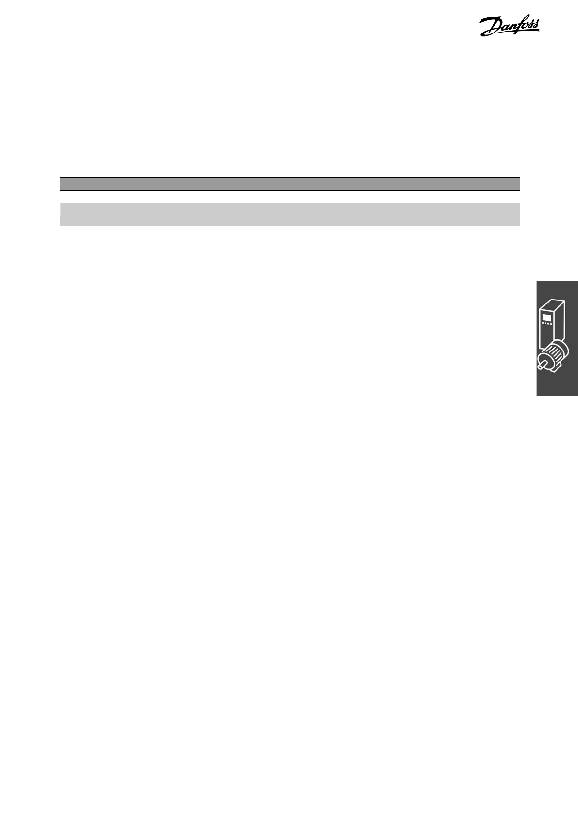
Velocity Synchronization (SYNCV)
Velocity synchronization (SYNCV) is closed loop velocity control where the set-point is the master velocity
multiplied by the gear-ratio and the actual velocity is measured by the slave encoder; position deviations
will not be corrected. Note however that using the Integral part of the PID controller will lead to some level
of position correction as the integral sum of velocity is equal to position.
The slave must be at least as fast and dynamic as
the master in order to maintain accurate synchronization, i.e. the slave must be able to match the
maximum velocity, acceleration and deceleration of
the master. Already during the design phase it is
thus important to consider making the least dynamic shaft the master as this shaft will anyway be
the limiting factor for the system performance.
Typical applications are:
− Synchronizing of two or more conveyors
− Material stretching
− Mixing
Application Example: Suit Case Conveyor Belt
Control behavior with velocity synchronization.
Two or more conveyor belts must run at the same
speed in order to get a smooth transfer of the suit
case from one conveyor belt to the next.
In addition to start and stop of velocity synchronizing the sample program has a manual mode with
the possibility to increase and decrease the velocity
via digital inputs.
NOTE: The following is just an example and the presented settings and programs might not cover the
complete functionality required by a real application.
It is assumed that the motor and encoder connections are checked and that all basic parameter settings
such as motor data, encoder data and PID controller are done. Instructions for setting up parameters can
be found in FC 300 Operating Instructions and MCO 305 Operating Instructions.
24 MG.33.L5.02 – VLT
®
is a registered Danfoss trademark
Page 25
MCO 305 Design Guide
__ Functions and Examples __
Parameter Settings and Commands for Conveyor Belt Application
The following MCO 305 parameters are relevant for
velocity synchronization:
Command Description Syntax Parameter
SYNCV Synchronization of velocity SYNCV –
ON ERROR GOSUB Definition of an error subroutine
Program Example: Velocity Synchronizing
/************************ Velocity synchronizing sample program ***********************/
// Inputs: 1 Start/stop synchronization
// 2 Start manual mode
// 3 Increase manual velocity
// 4 Decrease manual velocity
// 8 Clear Error
// Outputs: 1 In synchronizing mode
// 2 In manual mode
// 8 Error
/********************************* Interrupts **************************************/
ON ERROR GOSUB errhandle // In case of error go to error handler routine, this must always be included
/***************************** Basic settings *************************************/
VEL 100 // Sets maximum slave velocity related to parameter 32-80 Maximum velocity
ACC 100 // Sets slave acceleration related to parameter 32-81 Shortest ramp
DEC 100 // Sets slave deceleration related to parameter 32-81 Shortest ramp
/************************** Define application parameters *****************************/
LINKGPAR 1900 "Manual velocity" 0 100 0
LINKGPAR 1901 "Velocity step" 0 10 0
/*************************** Define flags and variables *******************************/
sync_flag = 0
done = 0
err = 0
man_vel = 0
/********************************** main loop *************************************/
MAIN:
IF (IN 1 == 1) AND (sync_flag == 0) THEN // Start synchronizing once when input 1 is high
SYNCV // Start velocity synchronizing mode
sync_flag = 1 // Set sync_flag to ensure synchronizing is only started once.
OUT 1 1 // Set "In synchronizing mode" output
ELSE
MOTOR STOP // Stop if input 1 is low.
sync_flag = 0 // Reset sync_flag after stop
OUT 1 0 // Reset "In synchronizing mode" output
ENDIF
IF (IN 2 == 1) AND (sync_flag == 0) THEN // Start manual mode if input 2 high and not synchronizing
OUT 2 1 // Set "In manual mode" output
man_vel = GET 1900 // Set manual velocity to parameter 1900
CVEL man_vel
CSTART // Start constant velocity mode
WHILE (IN 2 == 1) DO // Stay in manual mode while input 2 is high
CVEL man_vel // Update manual velocity
IF (IN 3 == 1) AND (done == 0) THEN // Increase manual velocity by one step when input 3 is set
32-0* Encoder 2 – Slave page
32-3* Encoder 1 – Master page 205
32-6* PID-Controller page
32-8* Velocity & Acceleration page 213
33-1* Synchronization page 218
ON ERROR GOSUB
name
name = name of the subroutine
201
210
MG.33.L5.02 – VLT® is a registered Danfoss trademark 25
Page 26

MCO 305 Design Guide
__ Functions and Examples __
man_vel = man_vel + GET 1901
done = 1
ELSEIF (IN 4 == 1) AND (done == 0) THEN // Decrease manual velocity by 1 step when input 3 is set
man_vel = man_vel - GET 1901
done = 1
ELSE
done = 0
ENDIF
ENDWHILE
CSTOP // Stop when leaving manual mode
OUT 2 0 // Reset "In manual mode" output when leaving manual mode
ENDIF
GOTO MAIN
/****************************** Sub programs start ********************************/
SUBMAINPROG
/******************************** Error handler ***********************************/
SUBPROG errhandle
err = 1 // Set error flag to remain in error handler until error is reset.
OUT 8 1 // Set error output
OUT 1 0 // Reset "In synchronizing mode" output in case of error
OUT 2 0 // Reset "In manual mode" output in case of error
WHILE err DO // Remain in error handler until the reset is received
IF (IN 8) AND NOT (IN 1) AND NOT (IN 2) THEN
// Reset error when Input 8 is high and input 1+2 is low.
ERRCLR // Clear error
err=0 // Reset error flag
ENDIF
ENDWHILE
OUT 8 0 // Reset error output
sync_flag = 0 // Reset sync_flag after an error
done = 0 // Reset done flag after an error
RETURN
/*******************************************************************************/
ENDPROG
/******************************* End of program **********************************/
Position/Angle Synchronization (SYNCP)
Position synchronization (SYNCP) is closed loop position control with a moving target where the set-point
(commanded position) is the master position multiplied by the gear-ratio also considering any position offset. The slave position is controlled based on this set-point and the actual position feedback from the slave
encoder. Any position deviation will continuously be corrected considering maximum velocity, acceleration
and deceleration of the slave. The gear-ratio is set as a fraction (numerator and denominator) to avoid
rounding errors e.g. when using prime numbers. The gear-ratio must be 100% correct, even the smallest
rounding error will lead to position drifting over time.
When starting position synchronizing the actual slave position will be locked to the actual master position, it
is thus necessary to bring the slave into the right physical position with respect to the physical position of
the master. This can be done manually or be means of an automatic homing procedure (requires external
reference switches or absolute encoders).
The slave must be faster and more dynamic than the master in order to maintain accurate synchronization
both at maximum master velocity and during acceleration/deceleration. I.e. the slave must be able to
exceed the maximum velocity, acceleration and deceleration of the master to allow it to catch up if getting
behind the master. Already during the design phase it is thus important to consider making the least dynamic shaft the master as this shaft will anyway be the limiting factor for the system performance.
26 MG.33.L5.02 – VLT
®
is a registered Danfoss trademark
Page 27
MCO 305 Design Guide
__ Functions and Examples __
Typical applications are:
− Bottle washing machines.
− Foil wrapping.
− Packaging machines.
− Conveyors.
− Multi axis hoists.
− Filling.
− Printing.
− Cut on the fly.
Control behavior with position synchronization
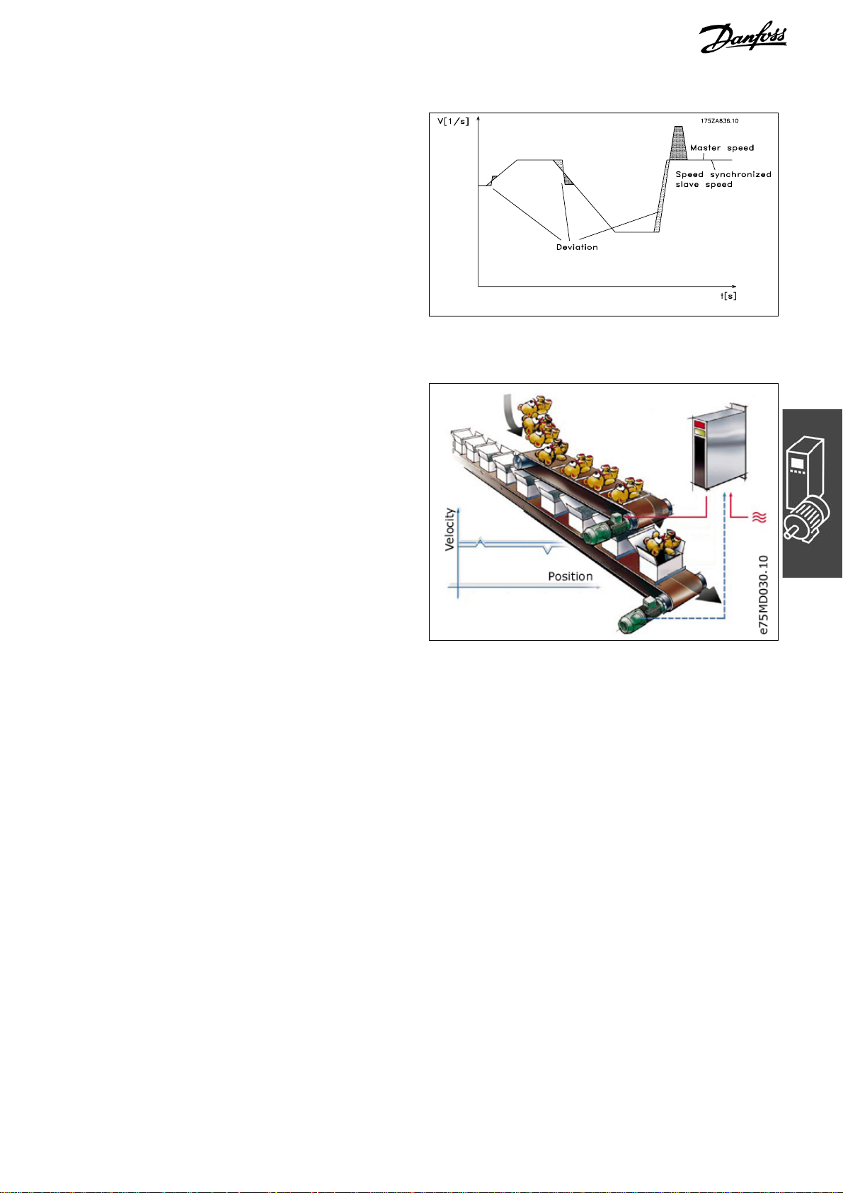
Application Example: Packaging with Fixed Product Distances
This application consists of two conveyors, 1 carrying empty boxes another one carrying teddy bears;
the purpose of the machine is to put teddies into the
boxes. Both boxes and teddies come with a fixed
distance and it is ensured that there is no slip
between the encoders and the boxes and teddies. It
is thus sufficient to position synchronize based on
the encoders. At start it is ensured that the master
(box conveyor) it always in the same position, the
teddy conveyor needs to be homed prior to starting
synchronization. There are 3 ways to ensure that
the teddies are aligned with the boxes when
starting:
− Adjust the physical position of the home/reference switch.
− Adjust home offset in parameter 33-01.
− Adjust position offset for synchronization in parameter 33-12.
NOTE: The following is just an example and the presented settings and programs might not cover the
complete functionality required by a real application.
It is assumed that the motor and encoder connections are checked and that all basic parameter settings
such as motor data, encoder data and PID controller are done. Instructions for setting up parameters can
be found in FC 300 Operating Instructions and MCO 305 Operating Instructions.
Parameter Settings and Commands for Packaging Application
The following MCO 305 parameters are relevant for
position synchronization:
MG.33.L5.02 – VLT® is a registered Danfoss trademark 27
32-0* Encoder 2 – Slave page
201
32-3* Encoder 1 – Master page 205
32-6* PID-Controller page
210
32-8* Velocity & Acceleration page 213
33-1* Synchronization page 218
Page 28
MCO 305 Design Guide
__ Functions and Examples __
Command Description Syntax Parameter
DEFSYNCORIGIN Defines master-slave relation for the
next SYNCP or SYNCM command
MOVESYNCORIGIN Relative shifting of the origin of
synchronization
PULSACC Sets acceleration for master
simulation
PULSVEL Sets velocity for master simulation PULSVEL v v = velocity in pulses per second
SYNCP Synchronization of angle/position SYNCP –
SYNCSTAT Queries flag for synchronization
status
SYNCERR Queries actual synchronization error
of the slave
DEFSYNCORIGIN
master slave
MOVESYNCORIGIN
mvalue
PULSACC a a = acceleration in Hz/s
res = SYNCSTAT –
res = SYNCERR –
master = reference position in qc
slave = reference position
mvalue = Relative offset
(Hz)
Position Synchronizing Sample Program
/************************* Position Synchronizing Sample Program ***********************/
// Inputs: 1 Start/stop synchronization
// 2 Start homing
// 3 Home switch
// 4 Increase offset
// 5 Decrease offset
// 8 Clear Error
// Outputs: 1 Within synchronizing accuracy, set accuracy window in par. 33-13
// 2 Homing done
// 8 Error
/****************************** Interrupts **************************************/
ON ERROR GOSUB errhandle
// In case of error go to error handler routine, this must always be included
/************************** Basic settings ************************************/
VEL 100 // Sets maximum slave velocity related to par. 32-80 Maximum velocity
ACC 100 // Sets slave acceleration related to par. 32-81 Shortest ramp
DEC 100 // Sets slave deceleration related to par. 32-81 Shortest ramp
/*********************** Define application parameters *****************************/
LINKGPAR 1900 "Offset step" 0 10000 0
LINKGPAR 1901 "Offset type" 0 1 0
/********************** Set parameters and flags ********************************/
SET I_FUNCTION_3 1 // Define input 3 as Home switch input
next_step = 0
home_done = 0
new_offset = 0
/************************************* main loop ******************************/
MAIN:
IF (IN 2 == 1) THEN // Start homing if input 2 high
HOME // Go to Home and set position to 0
home_done = 1 // Set home_done flag
OUT 2 1 // Set home done output
ENDIF
IF (IN 1 == 1) AND (home_done == 1) THEN // Start synchronizing when input 1 = 1 and homing done.
SYNCP // Start position synchronizing mode
28 MG.33.L5.02 – VLT
®
is a registered Danfoss trademark
Page 29

MCO 305 Design Guide
__ Functions and Examples __
old_offset = GET SYNCPOSOFFS
WHILE (IN 1 == 1) DO // Stay in synchronizing mode while input 1 = 1
IF (IN 4 == 1) THEN
GOSUB increase_offset
ELSEIF (IN 5 == 1) THEN
GOSUB decrease_offset
ENDIF
IF (SYNCSTAT & 4) THEN
OUT 1 1
ELSE
OUT 1 0
ENDIF
ENDWHILE
MOTOR STOP // Stop if input 1 is low.
home_done = 0 // Reset home_done flag after stop
OUT 1 0
OUT 2 0 // Reset home done output after stop
IF (new_offset != old_offset) AND (GET 132 == 0) THEN // Save absolute offset if changed
SAVE AXPARS // NOTE: Saving more that 10000 times can damage flash PROM
ENDIF
ENDIF
GOTO MAIN
/*************************** Sub programs start *********************************/
SUBMAINPROG
/***************************** Increase offset **********************************/
SUBPROG increase_offset
IF (Next_step) THEN // Check if next offset step is enabled
IF (GET 1901 == 0) THEN // Absolute offset
new_offset = old_offset + GET 1900 // Read existing offset and add step value
SET SYNCPOSOFFS new_offset // Set new position offset
ELSE // Relative offset
MOVESYNCORIGIN GET 1900 // Execute relative offset with offset step
ENDIF
ENDIF
Next_step=0 // Disable next offset step
ON TIME 500 GOSUB Enb_Step // Enable next offset step after 500 ms
RETURN
/*************************** Decrease offset ***********************************/
SUBPROG decrease_offset
IF (Next_step) THEN // Check if next offset step is enabled
IF (GET 1901 == 0) THEN // Absolute offset
new_offset = GET SYNCPOSOFFS - GET 1900
// Read existing offset and subtract step value
SET SYNCPOSOFFS new_offset // Set new position offset
ELSE // Relative offset
MOVESYNCORIGIN (- GET 1900) // Execute relative offset with - offset step
ENDIF
ENDIF
Next_step=0 // Disable next offset step
ON TIME 500 GOSUB Enb_Step // Enable next offset step after 500 ms
RETURN
/************************* Enable new offset step *******************************/
SUBPROG Enb_step
MG.33.L5.02 – VLT® is a registered Danfoss trademark 29
Page 30

MCO 305 Design Guide
__ Functions and Examples __
Next_step = 1 // Enable next offset step
RETURN
/***************************** Error handler ***********************************/
SUBPROG errhandle
err = 1 // Set error flag to remain in error handler until error is reset.
OUT 8 1 // Set error output
OUT 2 0 // Reset home done output in case of error
WHILE err DO // Remain in error handler until the reset is received
IF (IN 8) AND NOT (IN 1) THEN // Reset error when Input 8 is high and input 1 low.
ERRCLR // Clear error
err=0 // Reset error flag
ENDIF
ENDWHILE
OUT 8 0 // Reset error output
home_done = 0 // Reset home_done flag after an error
RETURN
/****************************************************************************/
ENDPROG
/***************************** End of program *********************************/
30 MG.33.L5.02 – VLT
®
is a registered Danfoss trademark
Page 31

MCO 305 Design Guide
__ Functions and Examples __
Marker Synchronization (SYNCM)
Marker synchronization (SYNCM) is extended position synchronizing where an additional position correction
is done to align a slave marker with a master marker. Master and slave marker signals can be the encoder
zero pulse or external sensors connected to digital inputs. As with position synchronizing it is possible to
adjust gear-ratio and offset, in addition a marker ratio can be set e.g. 1 master marker to 3 slave markers
which mean that every master marker will be aligned with every 3
The marker signals can be monitored by defining a position window, only one marker (the first one) will be
accepted within the marker window and any marker signal outside the marker window will be ignored.
Without marker windows every marker signal including noise pulses and jitter will be accepted and used to
correct the slave position. The first master marker and first slave marker after starting are not monitored as
the system does not know where the first marker is supposed to be. After detecting the first marker the
anticipated position of the following markers is known as the marker distance must be specified by parameter individually for master and slave.
When starting marker synchronization the initial behavior will be like position synchronization but when the
first set of markers has been detected marker correction will start. Which markers to use for the first
marker correction can be defined by parameter 33-23, by defining the start behavior it is possible to define
whether the slave must always wait for the master, catch up with the master or make the smallest
correction, see parameter 33-23 for a detailed description of the available options. Homing procedures are
thus not necessary prior to starting as the marker correcting will automatically align the slave with the
master.
The slave must be faster and more dynamic than the master in order to make marker correction and maintain accurate synchronization both at maximum master velocity and during acceleration/deceleration. I.e.
the slave must be able to exceed the maximum velocity, acceleration and deceleration of the master to
allow it to make marker correction and to catch up if getting behind the master. Already during the design
phase it is thus important to consider making the least dynamic shaft the master as this shaft will anyway
be the limiting factor for the system performance.
Typical applications are:
Basically the same application types as position
synchronizing but where one or more of the
following is true:
− Automatic alignment after start is required.
− Gear-ratio cannot be set 100% correct.
− There is slip somewhere between the
encoder and the part the must be
synchronized.
− Varying distance between products.
Control behavior with marker synchronization
rd
slave marker.
Application Example: Packaging with Varying Product Distance and Slip
This application consists of two conveyors, 1 carrying empty boxes and another one carrying teddy bears,
the purpose of the machine is to put teddies into the boxes. Both boxes and teddies are moved by friction
and can thus move on the conveyor belt. It means that there is no fixed relationship between the encoders
and the position of box and teddy bear and the distance can vary. It is therefore necessary to use external
marker detection on both boxes (master) and teddies (slave) in order to synchronize the teddy bear
position to the box position. Alignment can be obtained by adjusting the physical position of the marker
detectors or by adjusting the position offset in parameter 33-12.
MG.33.L5.02 – VLT® is a registered Danfoss trademark 31
Page 32

MCO 305 Design Guide
__ Functions and Examples __
In addition to start and stop of marker synchronizing the sample program has measuring of both
Master and Slave Marker Distance. The average
distance between the detected markers is
calculated and the marker distance parameters
(33-17 and 33-18) are automatically set.
NOTE: The following is just an example and the
presented settings and programs might not cover
the complete functionality required by a real
application.
It is assumed that the motor and encoder connections are checked and that all basic parameter
settings such as motor data, encoder data and PID
controller are done. Instructions for setting up
parameters can be found in FC 300 Operating
Instructions and MCO 305 Operating Instructions.
Parameter Settings and Commands for Packaging Application
The following MCO 305 parameters are relevant for
marker synchronization:
32-0* Encoder 2 – Slave page
32-3* Encoder 1 – Master page 205
32-6* PID-Controller page
32-8* Velocity & Acceleration page 213
33-1* Synchronization page 218
201
210
Command Description Syntax Parameter
DEFSYNCORIGIN Defines master-slave relation for
the next SYNCP or SYNCM
command.
MOVESYNCORIGIN Relative shifting of the origin of
synchronization.
PULSACC Sets acceleration for master
simulation.
PULSVEL Sets velocity for master simulation. PULSVEL v v = velocity in pulses per
SYNCM Synchronization of angle/position
with marker correction.
SYNCSTAT Queries flag for synchronization
status.
SYNCERR Queries actual synchronization
error of the slave.
IPOS Queries last index or marker
position of the slave.
MIPOS Queries last index or marker
position of the master.
DEFSYNCORIGIN
master slave
MOVESYNCORIGIN
mvalue
PULSACC a a = acceleration in Hz/s
SYNCM –
res = SYNCSTAT
res = SYNCERR –
res = IPOS –
res = MIPOS –
master = reference position in
qc
slave = reference position
mvalue = Relative offset
second (Hz)
32 MG.33.L5.02 – VLT
®
is a registered Danfoss trademark
Page 33

MCO 305 Design Guide
__ Functions and Examples __
Program Example: Marker Synchronization
/********************* Marker synchronizing sample program ************************/
// Inputs: 1 Start/stop synchronization
// 2 Measure slave marker distance
// 3 Measure master marker distance
// 5 Master marker
// 6 Slave marker
// 8 Clear Error
// Outputs: 1 Within synchronizing accuracy, set accuracy window in parameter 33-13
// 2 Marker measurement active.
// 8 Error
***************************** Interrupts ****************************************/
ON ERROR GOSUB errhandle
// In case of error go to error handler routine, this must always be included
/****************************** Basic settings ********************************/
VEL 100 // Sets maximum slave velocity related to parameter 32-80 Maximum velocity
ACC 100 // Sets slave acceleration related to parameter 32-81 Shortest ramp
DEC 100 // Sets slave deceleration related to parameter 32-81 Shortest ramp
/************************ Define application parameters *****************************/
LINKGPAR 1900 "Measuring velocity" 0 100 0
/************************* Set parameters and flags *******************************/
SET SYNCMTYPM 2 // Set master marker type to external
SET SYNCMTYPS 2 // Set slave marker type to external
sync_flag = 0
/****************************** main loop ***************************************/
MAIN:
IF (IN 1 == 1) AND (sync_flag == 0) THEN // Start synchronizing once when input 1 is high.
SYNCM // Start marker synchronizing mode
sync_flag = 1 // done flag
ELSE
MOTOR STOP // Stop when input 1 is low.
sync_flag = 0 // Reset sync_flag after stop.
ENDIF
IF (IN 2 == 1) AND (sync_flag == 0) THEN // Start measuring slave marker distance
GOSUB slave_measure // Note: Slave motor will rotate
ELSEIF (IN 3 == 1) AND (sync_flag == 0) THEN // Start measuring slave marker distance,
GOSUB master_measure // master must run.
ENDIF
GOTO MAIN
/*************************** Sub programs start **********************************/
SUBMAINPROG
/********************** Measure slave marker distance ******************************/
SUBPROG slave_measure
OUT 2 1 // Set "Marker measurement active" output
CVEL GET 1900 // Set measuring velocity
CSTART // Start constant velocity mode
old_ipos = IPOS // Read "old" marker position
marker_number = 0 // Reset variable
total_dist = 0 // Reset variable
skip_first = 0 // Reset variable
WHILE (IN 2 == 1) DO // Stay in measuring mode while input 2 high
new_ipos = IPOS // Read "new" marker position
IF (new_ipos != old_ipos) THEN // Check if a new marker was detected
marker_distance = new_ipos - old_ipos // Calculate marker distance
IF (marker_distance < 0) THEN // Change sign if negative
marker_distance = (marker_distance * -1)
ENDIF
MG.33.L5.02 – VLT® is a registered Danfoss trademark 33
Page 34

MCO 305 Design Guide
__ Functions and Examples __
IF (skip_first == 0) THEN // Do not use first value as it might be invalid
skip_first = 1
ELSE
marker_number = marker_number + 1 // Increment counter
total_dist = total_dist + marker_distance // Summarize marker distances
ENDIF
old_ipos = new_ipos // Set "old" marker position to "new" marker position
ENDIF
ENDWHILE
CSTOP // Stop when leaving slave marker measurement
SET SYNCMPULSS (total_dist rnd marker_number) // calculate average marker distance and set par.
OUT 2 0 // Reset "Marker measurement active" output
RETURN
/*********************** Measure master marker distance ****************************/
SUBPROG master_measure
OUT 2 1 // Set "Marker measurement active" output
old_mipos = MIPOS // Read "old" marker position
marker_number = 0 // Reset variable
total_dist = 0 // Reset variable
skip_first = 0 // Reset variable
WHILE (IN 2 == 1) DO // Stay in measuring mode while input 2 high
new_mipos = MIPOS // Read "new" marker position
IF (new_mipos != old_mipos) THEN // Check if a new marker was detected
marker_distance = new_mipos - old_mipos // Calculate marker distance
IF (marker_distance < 0) THEN // Change sign if negative
marker_distance = (marker_distance * -1)
ENDIF
IF (skip_first == 0) THEN // Do not use first value as it might be invalid
skip_first = 1
ELSE
marker_number = marker_number + 1 // Increment counter
total_dist = total_dist + marker_distance // Summarize marker distances
ENDIF
old_mipos = new_mipos // Set "old" marker position to "new" marker position
ENDIF
ENDWHILE
SET SYNCMPULSM (total_dist rnd marker_number) // calculate average marker distance and set par.
OUT 2 0 // Reset "Marker measurement active" output
RETURN
/******************************** Error handler ************************************/
SUBPROG errhandle
err = 1 // Set error flag to remain in error handler until error is reset.
OUT 8 1 // Set error output
OUT 2 0 // Reset "Marker measurement active" output in case of error
WHILE err DO // Remain in error handler until the reset is received
IF (IN 8) AND NOT (IN 2) THEN // Reset error when Input 8 is high and input 2+3 low
ERRCLR // Clear error
err=0 // Reset error flag
ENDIF
ENDWHILE
OUT 8 0 // Reset error output
sync_flag = 0 // Reset sync_flag after error
RETURN
/****************************************************************************/
ENDPROG
/********************************* End of program ******************************/
34 MG.33.L5.02 – VLT
®
is a registered Danfoss trademark
Page 35

MCO 305 Design Guide
__ Functions and Examples __
CAM Control
In order to realize CAM control, you need – depending on the application – at least one curve which
describes the slave position in relation to the master position, as well as the engaging and disengaging
behavior. Of course, many additional parameters are required for a CAM control which, together with the Fix
points of the curve, produces a curve profile.
The synchronization in CAM-Mode (SYNCC command) can also be performed with marker correction
(SYNCCMM and SYNCCMS). This would be required, for example, if the products are transported irregularly
on a conveyor belt, or if adding errors need to be compensated for.
Diagram of the principle
and the mechanical camshaft are shown on the
left, the curves for the electronic CAM control and
the electronic CAM box are shown on the right:
In order to create the curve profile, use the →
CAM-Editor. into which you first load the controller
parameters that have already been set. Then you
set the Fix points of the curve and define the
parameters required for your application. You can
enter all values in physical or user-defined units
under a Windows interface. You can constantly
control the curve profile graphically; in this way,
you can check velocity and acceleration of the slave
axis.
: The mechanical cam disc
Interpolation
The CAM-Editor calculates the curve from Fix points with the help of a spline interpolation. This is optimized
to a minimum torque. In order to prevent speed leaps in the case of repeated curve cycles, the velocity at
the beginning and the end is equated. You can choose between three types of curve for this calculation. In
either type, the interpolation takes account of the gradient of the curve at the beginning and the end. Either
the gradient at the beginning and at the end is averaged; or the gradient at the beginning of the curve is
also used for the end of the curve, or the gradient of the curve at the beginning and the end is set to zero.
Tangent Points for Straight Sections
For areas where the velocity must be constant and the acceleration = 0, you need to use tangent points. A
straight line will be drawn instead of a spline between these points.
Accuracy
The Fix points are used directly as interpolation points provided that this is permitted by the interval
distance. The CAM-Editor. performs a linear interpolation between the interpolation points. If a fixpoint is
not hit by the selected interval distance, then the corresponding slave reference value does not exist in the
interpolation table. You can avoid such deviations if you have activated → Snap on Grid.
Internal Realization as Array
The curve profiles are realized internally as arrays which you can call up by means of a DIM instruction and
the SETCURVE command.
MG.33.L5.02 – VLT® is a registered Danfoss trademark 35
Page 36

MCO 305 Design Guide
__ Functions and Examples __
Stamping of Boxes with Use-by Date
The following example explains step by step how to
edit the curve for this application of the CAM control and then how to incorporate it into your control
program.
A roller is supposed to stamp an inscription with a
length of 10 cm on cardboard boxes. The stamp
corresponds to a roller section of 120 degrees.
60 cardboard boxes are transported on the conveyor belt per minute. The cardboard boxes are
always transported on the conveyor belt at exactly
e75MD001.10
the same distance from each other (e.g. by means
of a mechanical set pattern). During the printing
process, the stamping roller and the cardboard box
must run in sync:
How to Edit the Curve Step by Step
1. Set the FC 300 with the required parameters.
2. Select this .zbc (or .cnf) file, APOSS will then automatically open the selected file as well as the CAM-
Editor.
Stand-alone APOSS:
Start → CAM-Editor and load this .zbc (or .cnf) file.
3. Determine the gearing factor of the master in MU units.
The input should be possible in 1/10 mm resolution.
The drive is connected with the conveyor belt by means of a gearing of 25:11; i.e. the motor makes 25,
the drive pulley 11 revolutions.
Gearing factor = 25/11
Incremental encoder directly on the master
drive; encoder resolution = 4096
The drive pulley has 20 teeth/revolution,
2 teeth correspond to 10 mm, thus 1 revolution corresponds to = 100 mm conveyor belt
feed or 1000/10 mm.
2048
55
Thus, the scaling factor is 1000.
Enter these values in the index card → Synchronization (the selected units should always be whole
numbers):
par. 33-10 Syncfactor Master = 2048
par. 33-11 Syncfactor Slave = 55
4. Enter the gearing factor of the slave in UU units:
Gearing factor = 5/1
Encoder resolution (increm. encoder) = 500
One revolution of the roller is 360 degrees. We
are going to work with a resolution of
1/10 degrees. This means that we are dividing
one revolution of the roller into 3600 work units:
3600
25
9
Scaling factor = 3600
Enter these whole number values in the index card → Encoder Data:
par. 32-12 User Unit Numerator = 25
par. 32-11 User Unit Denominator = 9
Slave positions [degrees]
stamp beginning 120°, end 240°
0
Area where master and slave
∗∗
4 4096 25/11
1000
4 500 5/1
∗∗
qc
=
UU 1 qc
===
25001500
must be in sync
Factor Scaling
=
qc
===
MU 1 qc
Factor Scaling
3600
Stamping roller = Slave
Conveyor belt
= Master
4000
×
11 1000
10-33 par.
11-33 par.
4 500 5
∗∗
=
12-32 par.
11-32 par.
∗∗
∗×∗
4 4096 25
∗∗
UU 1 qc
Master positions
[1/10 mm]
4 Resolution Encoder Factor Gearing
=
=
Master Syncfactor
Slave Syncfactor
4 Resolution Encoder Factor Gearing
=
Numerator Unit User
Denomintor Unit User
MU 1qc
MU1 qc
UU 1qc
36 MG.33.L5.02 – VLT
®
is a registered Danfoss trademark
Page 37

MCO 305 Design Guide
__ Functions and Examples __
5. Determine a whole number factor for the intervals in the index card → Curve Data so that the Fix points
are on the interpolation points. Set this using the “Set” button.
A complete cycle length of the master is 400 mm; this corresponds to 4000 MU.
The → Number of Intervals = 40 results in a reasonable interval time of 25 ms.
6. Define → Fix points for the conveyor belt
(master) and the roller (slave). The function
→ Snap on Grid should be activated.
7. Master and slave must run synchronously with
the same velocity between the position 1500
and 2500. This requires a straight line that is
determined by two tangent points.
Double-click in the column → Type for the
fixpoint at position 2500.
Alternatively, you can move the cursor to the
fixpoint 2500, click on the right mouse button
and select → Change Type in the subsequent
context menu. Since two tangent points are
always required, the previous one (at 1500)
will also be changed at the same time.
8. Activate the diagram of the → Velocity to
see the corresponding velocity curve:
9. Enter the → Cycles/min Master = 60 in the index card → Curve Info. This is the (maximum) number of
cardboard boxes that are processed per minute.
10. Verify whether the acceleration of the slave is within the limit. For this purpose, you must activate the
illustration of the → Acceleration and of the → Acc. Limit.
11. In order to load the curve into your control system, you must first save the file as a .zbc file by clicking
the “Save As” button. You will see the name of the curve and the number of array elements in the title
bar. You will need the latter for the DIM instruction during programming.
12. Load the .zbc file with the modified parameters and the – automatically generated – curve arrays into
the FC 300 by means of Parameters → Restore from file.
MG.33.L5.02 – VLT® is a registered Danfoss trademark 37
Page 38

MCO 305 Design Guide
__ Functions and Examples __
Program Example: Stamping of Boxes with Use-by Date
Since the curve is stored internally as an array, the DIM instruction must appear first in your program:
DIM stamping[92] // Number of elements from the title bar of the CAM-Editor
HOME // Slave axis performs a home run (switch for zero position on top)
// Afterwards, the slave will be in the zero position (0 degrees)
// (Omitted if an absolute encoder is used)
SETCURVE stamping // Set stamp curve
// Assumption: A box is positioned at the processing point with its front edge and the master stands idle
DEFMCPOS 1000 // 1000 corresponds to this position (front edge of box)
POSA CURVEPOS // Bring slave to the curve position that corresponds to the master position
SYNCC 0 // Change into and remain in CAM-Mode
SYNCCSTART 0 // Engage roller immediately with the set maximum velocity
// This does not cause any movement since the master is idle and in the correct position
// Now the master can be started
start: // Empty main loop so that program will not be terminated
// Additional processing could take place here
GOTO start
38 MG.33.L5.02 – VLT
®
is a registered Danfoss trademark
Page 39

MCO 305 Design Guide
__ Functions and Examples __
Printing of Cardboard Boxes with Marker Correction
If the boxes are not always transported at the
exact same distance from each other, markers will
be required that can recognize a box and correct
the synchronization.
The following section describes how you can adapt
the curve of the previous example to this
application.
Again, a roller is supposed to stamp an inscription
with a length of 10 cm on cardboard boxes. A
maximum of 60 boxes are transported on the
conveyor belt per minute. During the printing
operation, both the stamping roller and the box
must run in sync.
How to Edit a Curve for Synchronization with Marker
1. Steps 1 to 9 are the same as in the previous example.
10. Define the point pairs for the engaging and
disengaging in the list → Start-Stop Points. We
make the assumption that engaging takes
place at the beginning of the box and disengaging is to take place until the end of the box.
11. In the index card → Curve Data, determine the position in which the roller should stop if no other Slave
Stop Position is defined in the program.
The roller always needs to return to the position 0 degrees: → Slave Stop Position = 0
12. The photoelectric beam (external marker) has a distance of 237.5 mm from the processing point
(= stamp touches the cardboard box) and detects the beginning of the box (corresponding to master
position 1000). The marker distance is therefore 2375. Enter this value in the index card
→ Synchronization and define the permitted tolerance for the appearance of the markers and the
external marker type = 2 for the master.
par. 33-17 Master Marker Distance = 2375
par. 33-21 Master Marker Tolerance Window = 200
par. 33-19 Master Marker Type = 2
Enter the master position in the index card → Curve Data:
Master-Marker-Position = 100
MG.33.L5.02 – VLT® is a registered Danfoss trademark 39
Page 40

MCO 305 Design Guide
__ Functions and Examples __
13. Take a look at the curve profile in order to
determine when the correction of the synchronization may begin at the earliest and when it
must be finished. The vertical green line indicates the master position where the marker is
recognized, the light green area shows the
tolerance window for the appearance of the
master marker.
At the earliest, the correction may begin when
the printing of a box has been completed,
since any change of velocity during the
printing process would damage the box. The
correction must be finished completely when
the next cardboard box reaches the processing
point.
In this example, the master positions at the end and beginning of a box are quite suitable:
Correction Start = 3000
Correction End = 1000Enter the values in the index card → Curve Data; the depiction of the area
is shaded in blue in the curve profile.
14. Verify whether the velocity and acceleration of the slave remain within the limit. For this purpose, you
must activate the illustration of the → Velocity and of the → Vel.-Limit and then the illustration of
the → Acceleration and of the → Acc.-Limit.
15. Click the “Save as” button to save the .zbc file, for example “marker”.
16. Load the .zbc file with the modified parameters and the – automatically generated – curve arrays into
the FC 300 by means of Parameters → Restore from file.
Program Example: Synchronization with Marker
Since the curve is stored internally as an array, the DIM instruction must appear first in your program:
/******** Printing of Cardboard Boxes with Marker Correction (Synchronization with Marker) ******/
DIM marker[112] // Number of elements from the title bar of the CAM-Editor
HOME // Slave axis performs a home run (switch for zero position on top)
// Afterwards, the slave will be in the zero position (0 degrees)
// (Omitted if an absolute encoder is used)
SETCURVE marker // Set stamp curve with marker
dist = GET SYNCMPULSM // Distance to sensor
DEFMCPOS (1000-dist) // This is the location that corresponds to the sensor signal
SET SYNCMSTART 2000 // Counting of the master pulse does not begin
// until the next edge comes from the sensor
SYNCCMM 0 // Synchronize in CAM-Mode until motor stop
SYNCCSTART 1 // Engage roller with start point pair 1
// Synchronous operation
WAITI 4 ON // Wait for input signal when conveyor belt is being switched off
SYNCCSTOP 2 0 // Disengage roller with stop point pair 1 and stop at position 0 degrees
40 MG.33.L5.02 – VLT
®
is a registered Danfoss trademark
Page 41

MCO 305 Design Guide
__ Functions and Examples __
If the Sensor Distance is Larger than one Master Cycle Length
In many applications, the marker cannot be placed
within one master cycle length, for example in the
case of the following equipment for the production
of plastic bags:
Since no markers can be installed between the
slaves here, there is only a marker reader in this
application; the welding station is much farther
away than one master cycle length. Since the
distance of the sensor is larger than one master
cycle length, a buffer is provided for the marker
deviation. When the marker appears, the value is
entered in the buffer and read out upon the
appearance of the next marker: see figure.
In order to assess in what area corrections may be
made, you should subtract the master cycle length
as often as necessary until the value is < 1 master
cycle length. This is the maximum permitted
distance for making corrections. In this example, it
is 6375 – 4000 = 2375 and thus the same
correction range as in the previous example.
Problematic Situations in the Determination of the Marker Distance
If the marker is mounted so close to the processing
point that there is no time left to correct the synchronization after the marker has been detected,
then you can remedy the problem only through
mechanical modification of the marker.
On the other hand, the same effect might also
occur if the marker distance is larger than the
master cycle length and if an insufficient distance
likewise remains after the subtraction of this value,
for example:
The value is entered into the buffer when the marker appears. The buffer is read out only when the next
marker is recognized. This means that the marker is only “recognized” at the master position 900 and that
there is little time left in our example to correct the error. It is the same effect as if the sensor had been
mounted at the value (distance – master cycle length) or (4100 – 4000), respectively, i.e. only 10 mm in
front of the processing point. See the effects (correction area) by means of the two screen shots.
MG.33.L5.02 – VLT® is a registered Danfoss trademark 41
Page 42

MCO 305 Design Guide
__ Functions and Examples __
Thus, it would be better to install the sensor in such a way that the distance to the processing point is either
smaller or substantially larger than one master cycle length; here, for example, at a distance of 3900. Then
it is possible to correct from 2500 to 1000.
Alternatively, the sensor could be installed further away, for example at a distance of 7900; this has the
same effect as if the sensor had been installed at distance – master cycle length (7900 – 4000), i.e. 3900 in
front of the processing point. This allows enough time to correct the synchronization.
If this cannot be done mechanically, then the values must be manipulated somewhat in order to avoid the
solution with the buffer. Please proceed as follows:
Subtract a value x from the actual distance so that the distance becomes < than the master cycle length,
for example 4100 – 200 = 3900. You also subtract the value x from the master position, i.e. 1000 – 200 =
800.
Enter both values in the index cards: → Synchronization and → Curve Data:
par. 33-17 Master Marker Distance = 3900
Master Marker Position = 800
Since no buffer is generated now, it would be possible to correct from 2500 to 800, for example
Slave Synchronization with Marker
In the following example, the conveyor belt is the
slave and the stamp roller the master, since the
take-up and delivery of the dye must be continuous
for a uniform printing process. A maximum of
20 cardboard boxes are transported on the conveyor belt per minute. The distance of the boxes is
not larger than one master cycle length. Stamp
roller and box must run in sync during the printing
operation: see figure.
In contrast to the synchronization with master
marker correction, here the slave position is being
corrected instead of the curve.
42 MG.33.L5.02 – VLT
®
is a registered Danfoss trademark
Page 43

MCO 305 Design Guide
__ Functions and Examples __
How to Edit a curve for the Slave Synchronization
1. Set the FC 300 with the required parameters and save these parameters with Parameters → Save to file
with the extension “zbc”.
2. This .zbc file must be open in the CAM-Editor.
3. Determine the gearing factor of the master in MU units.
Gearing factor = 5/1
Encoder resolution (Incremental encoder) = 500
One revolution of the roller is 360 degrees. We are going to work with a resolution of 1/10 degrees.
This means that we are dividing one revolution of the roller into 3600 work units:
Scaling factor = 3600
4 Resolution Encoder Factor Gearing
Factor Scaling
Enter these whole number values in the index card → Synchronization:
Par. 33-10 Syncfactor Master = 25
Par. 33-11
Syncfactor Slave = 9
4. Enter the gearing factor of the slave in UU units:
The input should be possible in 1/10 mm resolution.
The drive is connected with the conveyor belt by means of a gearing of 25:11; i.e. the motor makes 25,
the drive pulley 11 revolutions.
Gearing factor = 25/11
Incremental encoder directly on the master drive; encoder resolution = 4096
The drive pulley has 20 teeth/revolution, 2 teeth correspond to 10 mm, thus 1 revolution corresponds
to = 100 mm conveyor belt feed or 1000/10 mm.
Thus, the scaling factor is 1000
∗∗
=
MU 1qc
∗∗
Factor Scaling
UU 1qc
=
4 Resolution Encoder Factor Gearing
Enter these values in the index card → Encoder Data:
Par. 32-12 User Unit Numerator = 2048
Par. 32-11 User Unit Denominator = 55
5. Determine a whole number factor for the intervals in the index card → Curve Data so that the Fix points
are on the interpolation points.
A complete cycle length of the master is 360 degrees; this corresponds to 3600 MU.
For a master cycle length of 3600, the → Number of Intervals = 36 produces a reasonable interval time
of 27.7 ms. Set these two values using the “Set” button in the Curve Data index card.
6. Define → Fix points for the roller (slave) and
the conveyor belt (master). The function
→ Snap on Grid should be activated.
Point Master Slave Type
1 0 0 C
2 1200 1500 C
3 2400 2500 C
4 3600 4000 C
7. Master and slave must run synchronously with
the same velocity between the master positions 1200 to 2400. For this, you need to have
a straight line that is determined with two tangent points. Double-click in the column → Type
for the fixpoint at position 2400.
Point Master Slave Type
1 0 0 C
2 1200 1500 T
3 2400 2500 T
4 3600 4000 C
MG.33.L5.02 – VLT® is a registered Danfoss trademark 43
Page 44

MCO 305 Design Guide
__ Functions and Examples __
Activate the diagram of the → Velocity to
see the corresponding velocity curve as it is
shown in this figure:
8. Enter the → Cycles/min Master = 20 in the
index card → Curve Info. This is the (maxi-
mum) number of cardboard boxes that can be
processed per minute.
9. Verify whether the acceleration of the slave is
within the limit. For this purpose, you must
activate the illustration of the → Acceleration
and of the → Acc. Limit.
10. Define in the list → Start-Stop Points with
some safe distance in order to start the synchronization at the beginning. Engaging should
take place between 20 and 100 degrees
because it must be completed at 120 degrees.
11. In the index card → Curve Data, define the position where the conveyor belt should stop if no other
Slave Stop Position is being defined in the program:
The conveyor belt should always stop in position 0:
Slave Stop Position = 0
12. The photoelectric beam (external marker) has a distance of 390 mm from the processing point (=
stamp touches the box) and detects the beginning of the box (corresponds to slave position 1000).
Thus, the marker distance is 3900. Enter this value in the index card → Synchronization and define the
permitted tolerance for the appearance of the markers and the external marker type = 2 for the slave:
Par. 33-18 Slave Marker Distance = 3900
Par. 33-22 Slave Marker Tolerance Window = 200
Par. 33-20 Slave Marker Type = 2
Enter the master position in the index card → Curve Data:
Slave-Marker-Position = 1000
13. Take a look at the curve profile in order to determine when the correction of the synchronization may
begin at the earliest and when it must be finished. The green horizontal line indicates the master
position where the marker is recognized, the light green area shows the tolerance window for the
appearance of the master marker.
At the earliest, the correction may begin when the printing of a cardboard box has been completed,
since any change of velocity during the printing process would damage the printing stamp and/or the
box. Also, the correction must have been completed in its entirety when the next box arrives at the
processing point. In this example, the slave positions at the end and beginning of a box are quite
suitable. Enter the values in the index card → Curve Data:
Correction Start = 2800
Correction End = 750
14. Verify whether the velocity and acceleration of the slave remain within the limit. For this purpose, you
must activate the illustration of the → Velocity and of the → Vel.-Limit and then the illustration of
the → Acceleration and of the → Acc.-Limit.
15. Click the “Save as” button to save the .zbc file.
16. Load the .zbc file with the modified parameters and the – automatically generated – curve arrays into
the FC 300 by means of Parameters → Restore from file.
44 MG.33.L5.02 – VLT
®
is a registered Danfoss trademark
Page 45

MCO 305 Design Guide
__ Functions and Examples __
Program Example: Slave Synchronization with Marker
In order to determine the master position, a switch on the master is required that indicates the zero
position. In order to put the slave into the correct position, it will be moved forward to the photoelectric
beam. This corresponds to the beginning of the box = 1000. Then the slave will be moved further by 2900
(= marker distance 3900–1000); thus, the slave is exactly in front of the processing point with the
beginning of the cardboard box 1000, i.e. at slave position 0.
DIM slavesync[108] // Number of elements from the title bar of the CAM-Editor
HOME // Slave axis performs a home run (switch for zero position on top)
// afterwards, the slave will be in the zero position (0 degrees)
// (Omitted if an absolute encoder is used)
DEFMCPOS 0 // Curve starts at master position 0
SET SYNCMSTART 2000 // Counting of the master pulse does not begin
// until the next edge comes from the sensor
SETCURVE slavesync // Set curve for the slave synchronization
CSTART // Go to start
CVEL 10 // Go forward slowly until photoelectric beam appears
oldi = IPOS // oldi = last marker position of the slave
WHILE (oldi == IPOS) DO // Wait until box is detected
ENDWHILE
POSA (IPOS + 2900) // Move box forward by 2900
SYNCCMS 0 // Synchronize in CAM-Mode
SYNCCSTART 1 // Engage with start-stop point pair 1
MG.33.L5.02 – VLT® is a registered Danfoss trademark 45
Page 46

MCO 305 Design Guide
__ Functions and Examples __
CAM Box
The mechanical camshaft is also reproduced by one (or more) curves. In order to realize a CAM box, it must
be possible to engage and disengage the slave at specific master positions over and over again.
This is possible with APOSS with the interrupt command ON MAPOS and ON APOS .. GOSUB. It is possible
to call up a subprogram whenever a defined master position has been passed (both in the positive or
negative direction, to be precise).
It is possible to realize many applications that are typical for the packaging industry in connection with a
curve profile in which several have been defined for engaging and disengaging.
Program Example of a CAM Box
After a cardboard box has been printed, the fresh
print is to be dried immediately in the air stream:
Air for drying is blown
on the fresh printing
surface for 300ms
Photoelectric beam
(external marker)
Stamping roller
= Slave
e75MD007.10
Master positions
[1/10 mm]
Processing point
ON MCPOS 2500 GOSUB drier
// Call up a subprogram when the master position 2500 is passed in positive direction
SUBMAINPROG
SUBPROG drier
OUT 1 1 // Turn on drier
DELAY 300 // Dry for 300 ms
OUT 1 0 // Turn off drier
RETURN
ENDPROG
40000 25001500
conveyor belt
= Master
46 MG.33.L5.02 – VLT
®
is a registered Danfoss trademark
Page 47

MCO 305 Design Guide
__ Functions and Examples __
Mechanical Brake Control
In applications controlled by MCO 305 involving an electro-mechanical brake it normally makes sense to
control the brake from the MCO 305 application program to avoid situations when the position controller of
MCO 305 attempts to move the motor while the brake is still engaged.
Controlling the brake from the MCO 305 application
program can be combined with the Mechanical
brake control of FC300 by using 2 outputs in series
e.g. Digital output 29 set to Mechanical brake
control (par. 5-31) and relay output 1 set to MCO
controlled (par. 5-40 [0]) and connect the brake as
shown below:
Program Example for Relative Positioning with Mechanical Brake
/**********************************************************************/
Inputs: 1 Go to position
8 Clear Error
Outputs: 1 In position
8 Error
11 Relay output for mechanical brake
/************************** Interrupts **********************************/
ON ERROR GOSUB errhandle
// In case of error go to error handler routine, this must always be included
/************************ Define flags *********************************/
flag = 0
/*********************** Basic settings ******************************/
VEL 80 // Sets positioning velocity related to par. 32-80 Maximum velocity.
ACC 100 // Sets positioning acceleration related to par. 32-81 Shortest ramp.
DEC 100 // Sets positioning deceleration related to par. 32-81 Shortest ramp.
/******************* Define application parameters *************************/
LINKGPAR 1900 "Box height" 0 1073741823 0
LINKGPAR 1901 "Brake close delay" 0 1000 0
LINKGPAR 1902 "Brake open delay" 0 1000 0
/******************* Initialize drive to safe state *************************/
GOSUB engage // Ensure that mechanical brake is closed after power up.
/****************************** main loop ******************************/
MAIN:
IF (IN 1 == 1) AND (flag == 0) THEN
// Go to position once (ensured by flag) when input 1 is high.
GOSUB disengage // Open mechanical brake before start.
OUT 1 0 // Reset "In position" output.
POSR (GET 1900) // Go to position.
OUT 1 1 // Set "In position" output.
flag = 1 // Set "flag" to ensure that distance is only traveled once.
ELSEIF (IN 1 == 0) AND (flag == 1) THEN // Stop once when input 1 is low
MOTOR STOP // Stop if input is low.
flag = 0 // Reset "flag" to enable new positioning.
GOSUB engage // Close mechanical brake after stop.
ENDIF
GOTO MAIN
/********************** Sub programs start ********************************/
SUBMAINPROG
/******************* Engage mechanical brake ******************************/
MG.33.L5.02 – VLT® is a registered Danfoss trademark 47
Page 48

MCO 305 Design Guide
__ Functions and Examples __
SUBPROG engage
OUT 11 0 // Close mechanical brake.
DELAY (GET 1901)
// Wait to ensure that brake is engaged before releasing the motor.
MOTOR OFF // Stop position control and coast the motor.
RETURN
/***************** Disengage mechanical brake *****************************/
SUBPROG disengage
MOTOR ON // Enable drive and start position control.
DELAY (GET 1902)
// Wait to ensure that motor is magnetized before opening the brake.
OUT 11 1 // Open mechanical brake.
RETURN
/********************** Error handler *************************************/
SUBPROG errhandle
OUT 11 0 // Close mechanical brake in case of error.
err = 1 // Set error flag to remain in error handler until error is reset.
OUT 8 1 // Set error output.
WHILE err DO // Remain in error handler until the reset is received.
IF IN 8 THEN // Reset error when Input 8 is high.
ERRCLR // Clear error.
err=0 // Reset error flag.
ENDIF
ENDWHILE
OUT 8 0 // Reset error output.
flag = 0 // Reset "flag" to enable new positioning.
RETURN
/*********************************************************************/
ENDPROG
/************************* End of program *******************************/
48 MG.33.L5.02 – VLT
®
is a registered Danfoss trademark
Page 49

MCO 305 Design Guide
__ Functions and Examples __
Limited-Jerk
Understanding Limited-Jerk Movements
Limited-jerk movements are similar to normal Trapezoidal movements except that the user may control the
"gentleness" of the acceleration and deceleration ramps. This allows the user to limit the "jerk" caused by
the "instantaneous" acceleration of a Trapezoidal movement.
Typical applications where limited jerk is required:
– lift
– movement of heavy loads
As an example, the following chart shows the acceleration, velocity, and position curves for a Trapezoidal
movement from one position to another position. The sharp changes in acceleration cause the motor to
experience a “jerk” at the beginning and end of each velocity ramp.
The following chart shows the same movement done using a Limited-jerk movement. Note that the acceleration changes are no longer "instantaneous" and that the "corners" of the velocity curve have become
rounded. This will result in a smoother motor movement. It will also require slightly longer to get to the
desired target position because the motor takes longer to accelerate to maximum acceleration.
MG.33.L5.02 – VLT® is a registered Danfoss trademark 49
Page 50

MCO 305 Design Guide
__ Functions and Examples __
The user can control the “gentleness” of the acceleration ramp using 4 parameters:
Parameter Limited Jerk
JERKMIN: Acceleration ramp-up constant. This specifies the number of milliseconds required to ramp the
acceleration up
JERKMIN2: Acceleration ramp-down constant. This specifies the number of milliseconds required to ramp
the acceleration down from maximum acceleration to 0 (i.e. normally to constant maximum
velocity). If set to 0, this will default to the same value as JERKMIN.
JERKMIN3: Deceleration ramp-up constant. This specifies the number of milliseconds required to ramp the
deceleration up
as JERKMIN.
JERKMIN4: Deceleration ramp-down constant. This specifies the number of milliseconds required to ramp
the deceleration down
this will default to the same value as JERMIN.
These constants correspond to the "slopes" of the different portions of the acceleration curve. This is shown
in the chart below. When set to larger and larger numbers, the acceleration and/or deceleration will become
gentler and gentler as the ramps become longer and longer. Note that the acceleration slope determined by
the JERKMIN acceleration ramp-up constant will be used whenever the acceleration is being ramped-up.
is not used only to ramp-up from 0 to maximum acceleration. Similarly, JERKMIN2 is used whenever the
acceleration is being ramped-down, JERKMIN3 is used whenever the deceleration is being ramped-up, and
JERKMIN4 is used whenever the deceleration is being ramped-down.
from 0 to maximum acceleration.
from 0 to maximum deceleration. If set to 0, this will default to the same value
from maximum deceleration to 0 (i.e. normally to 0 velocity). If set to 0,
It
Limited-jerk movements will not normally exceed the velocity and acceleration limits set for the controller
(e.g. limits set by the VEL, ACC, DEC, etc., commands). In the above chart, these limits can be recognized
by the “plateaus” in the acceleration curve. If the current velocity and/or acceleration are outside these
limits when the Limited-jerk movement is started, then the movement is accelerated or decelerated as
necessary to bring the movement within the set limits.
It is important to understand that for Limited-jerk movements, “acceleration” is defined as “speeding up” in
direction (i.e. either forwards or backwards) and "deceleration" is defined as "slowing down" in either
either
direction. A result of this is that maximum velocity, maximum acceleration, maximum deceleration, and the
four JERKMIN values are all independent of the direction of movement
. This can have important consequences when a Limited-jerk movement must “reverse” the direction of the motor, particularly when maximum
deceleration differs from maximum acceleration. In this case, the Limited-jerk movement will ensure that
the deceleration ramp flows smoothly into an acceleration ramp at exactly 0 velocity when the direction
changes and without exceeding either the deceleration or acceleration limits.
50 MG.33.L5.02 – VLT
®
is a registered Danfoss trademark
Page 51

MCO 305 Design Guide
__ Functions and Examples __
A Limited-jerk movement can be used in three different situations:
1. Stopping from the current velocity and acceleration (where the final position is not important).
2. Changing from the current velocity and acceleration to a specified constant velocity (where the positions
are not important).
3. Moving from the current position (and the current velocity and acceleration) and stopping at a specified
position.
Examples
In the following examples, maximum acceleration has been set to a value higher than maximum deceleration so the motor can speed up faster than it can slow down. As well, JERKMIN has been set smaller than
JERKMIN2, JERKMIN2 smaller than JERKMIN3, and JERKMIN3 smaller than JERKMIN4. This was done so
that the various segments of the curves can be visually distinguished in the charts. The four JERKMIN
values have been labeled simply J1, J2, J3, and J4.
Stopping
This chart shows a stopping movement that begins
from a positive constant velocity. The curve
consists of a deceleration ramp-up segment (using
JERKMIN3), followed by a constant deceleration
segment (at maximum deceleration), and finally a
deceleration ramp-down segment to 0 velocity
(using JERKMIN4).
This chart shows a stopping movement that begins
from a positive velocity and a positive acceleration.
Since the initial acceleration is positive, the curve
must start with an acceleration ramp-down segment to 0 acceleration (using JERKMIN2). This will
then be followed by a deceleration ramp-up segment (using JERKMIN3), a constant deceleration
segment, and a deceleration ramp-down segment
to 0 velocity (using JERKMIN4).
MG.33.L5.02 – VLT® is a registered Danfoss trademark 51
Page 52

MCO 305 Design Guide
__ Functions and Examples __
The chart below shows a stopping movement that begins from a negative velocity and a very high deceleration. (It is a deceleration because the speed is slowing down.) However, because the initial deceleration is
so high, the motor is unable to stop without overshooting 0 velocity and ‘coming back’.
So the curve starts with a deceleration ramp-down
segment (using JERKMIN4) to slow the deceleration
as much as possible before reaching 0 velocity. At
0 velocity, the ‘deceleration’ becomes an
‘acceleration’ because the direction has changed.
Hence, the curve continues by ramping-down the
acceleration
acceleration. The motor is now at a constant
positive velocity and so the curve will finish in the
normal way with a deceleration ramp-up segment
(using JERKMIN3), a constant deceleration
segment (very short in this example), and a
deceleration ramp-down segment to 0 velocity
(using JERKMIN4).
Changing to a Constant Velocity
This chart shows a movement that begins from a
positive constant velocity and increases its speed
to a higher positive constant velocity. This curve
consists of an acceleration ramp-up segment (using
JERKMIN), followed by a constant acceleration
segment (at maximum acceleration), and finally an
acceleration ramp-down segment to constant
velocity (using JERKMIN2). Note that the deceleration JERKMIN3 and JERKMIN4 values are not used
because there is never any deceleration.
(using JERKMIN2) until it gets to 0
Next chart shows a movement that begins from a
high positive constant velocity and decreases its
speed to a lower positive constant velocity. This
curve consists of a deceleration ramp-up segment
(using JERKMIN3), followed by a constant
deceleration segment (at maximum deceleration),
and finally a deceleration ramp-down segment to
constant velocity (using JERKMIN4). Note that the
acceleration JERKMIN and JERKMIN2 values are not
used because there is never any acceleration.
52 MG.33.L5.02 – VLT
®
is a registered Danfoss trademark
Page 53

MCO 305 Design Guide
__ Functions and Examples __
Next chart is similar to the previous example
except that it begins with a positive acceleration. In
this case, the curve must start with an acceleration
ramp-down segment (using JERKMIN2). Once the
acceleration reaches 0, then the curve can continue
as before.
The chart below shows a movement that begins with a negative constant velocity and changes direction to a
positive
the curve begins with a deceleration ramp-up segment (using JERKMIN3) until it reaches maximum deceleration.
The deceleration continues at maximum deceleration until it reaches 0 velocity. Note that there is
no deceleration ramp-down segment because the
movement is not stopping. At exactly 0 velocity,
the direction reverses and the movement is now
accelerating
mum acceleration is higher than maximum deceleration for this example, the curve is now able to
include an acceleration ramp-up segment (using
JERKMIN). The curve finishes in the normal way
with a constant acceleration segment and an
acceleration ramp-down segment to constant
velocity (using JERKMIN2).
constant velocity. The curve must start by slowing down the speed so that it can ‘turn around’. Hence
in the other direction. But since maxi-
Moving to a Specified Position
The chart below shows a ‘normal’ movement from being stopped at one position and then moving forward
to stop at another position. The curve starts with an acceleration ramp to maximum velocity. This portion of
the curve will be similar to the first of the examples shown in "Changing to a Constant Velocity". The curve
is simply changing to a constant velocity where the constant velocity is the maximum velocity.
Hence, the curve will consist of an acceleration ramp-up segment (using JERKMIN), a constant acceleration
segment at maximum acceleration, and then an acceleration ramp-down segment to maximum velocity
(using JERKMIN2).
The movement then proceeds at maximum velocity
until it needs to start the deceleration ramp that
will stop the movement at the desired position. The
deceleration ramp is identical to the first of the
examples shown in “Stopping”. The curve will
consist of a deceleration ramp-up segment
(JERKMIN3), followed by a constant deceleration
segment (at maximum deceleration), and finally a
deceleration ramp-down segment to 0 velocity
(using JERKMIN4) stopping at the desired position.
MG.33.L5.02 – VLT® is a registered Danfoss trademark 53
Page 54

MCO 305 Design Guide
__ Functions and Examples __
Next chart shows a typical ‘short’ movement where
maximum velocity cannot be reached. In this case,
the curve ramps-up the acceleration (using
JERKMIN) for as long as possible. This may or may
not reach maximum acceleration, depending on
how far away the target position is. There will then
be an acceleration ramp-down (using JERKMIN2),
followed immediately by a deceleration ramp-up
(using JERKMIN3). Again, depending on the target
position, there may or may not be a constant
deceleration segment. The curve ends with a
deceleration ramp-down to 0 velocity at the target
position.
The chart below shows an example where the motor is initially moving in the “wrong” direction and must
turn around and ‘go back’ to the target position. Since it must “turn around”, the curve starts with a
deceleration ramp-up segment (using JERKMIN3) to maximum deceleration.
This will slow the speed down until it turns around. Deceleration continues at maximum deceleration until 0
velocity is reached and the direction reverses. At exactly this point, the motor is now ‘speeding up’" but in
the other
From this point, the curve is similar to a normal
movement to a target position, except that the
whole curve is inverted because the direction has
changed. The curve will have an acceleration rampup segment (going backwards), it may or may not
have a constant acceleration segment, it will have
an acceleration ramp-down segment, it may or
may not have a constant velocity segment, it will
have a deceleration ramp-up segment, it may or
may not have a constant deceleration segment,
and finally it will have a deceleration ramp-down to
the target position.
direction.
54 MG.33.L5.02 – VLT
®
is a registered Danfoss trademark
Page 55

MCO 305 Design Guide
PC Software Interface
Specifics of the User Interface
You should be familiar with the basic functions and terminology of the Microsoft Windows interface, because
this manual does not explain the basics, but the specifics of the PC User Interface.
For programming the MCO 305 the VLT® Motion Control Tool MCT 10 is used. With that you also start the
integrated APOSS software for developing control programs and for editing curves.
Projects can be programmed off line or by means of Networking online.
– Online: When MCT 10 has a connection established to the drive, then APOSS will use the drive
connection that MCT 10 has already established.
– Offline: All the features that allow to switch drives or connect to multiple drives or to read current
parameters are enabled.
The selection of operating mode is done by MCT 10 at start-up of APOSS and can not be changed while
APOSS is running.
When APOSS is started by MCT 10, then APOSS will connect to only a single drive. Hence, all the features
that allow APOSS to switch drives or connect to multiple drives are disabled.
When neither MCT 10 is used online nor offline APOSS will be used in a stand-alone mode.
MG.33.L5.02 – VLT® is a registered Danfoss trademark 55
Page 56

MCO 305 Design Guide
__ PC Software Interface __
The APOSS Window
The APOSS Window allows simultaneous access both to an APOSS program and to a controller. Multiple
APOSS windows can be opened, each accessing a different APOSS program and a different controller.
The Edit Window displays the APOSS program being edited and provides all the usual text editing features.
Different colors are used to distinguish between comments, program sections, operators, numbers, etc. You
can alter the colors using Settings → Editor.
The Communication Window displays both messages from the APOSS-IDE (e.g. compiler messages) and
messages from the controller (e.g. programmed PRINT commands). Messages from the controller will be
prefixed by the controller ID number (e.g. “[01]” in the above example).
The Watch Window is useful during debugging. It allows the user to “watch” various aspects of both the
controller and the executing program while the controller is operating. See Development → Watch Add for a
description of how to use the Watch Window.
Title and Tool Bar
The Title bar displays the name of the APOSS program. If a controller is connected, then the controller ID
number and the connection interface type will also be displayed. In the event of a controller error, the error
is also shown in the title bar.
The Tool bar offers “single-click” access to several
commonly used functions. These functions are
described later in the manual.
56 MG.33.L5.02 – VLT
®
is a registered Danfoss trademark
Page 57

MCO 305 Design Guide
__ PC Software Interface __
Popup Menus
Popup menus are provided at certain program locations if the right mouse button is clicked. For
example, the context menu in the Edit Window or a
selection menu in Tools → CAM Editor for inserting or
deleting Fix Points. The popup menus are closed
automatically when the selected function is executed
or if any other location on the screen is clicked with
the left mouse button.
Function Keys
Frequently used functions are assigned to function keys:
[F1] Access on-line help
[F2] Skip to the next bookmark
[F3] Find next (if “Find” has been used)
[F4] Check the syntax of the program
[F5] Execute the program (see also Execute)
[F9] Single-step through the program (debug mode only)
[F11] Access on-line help for system process information
[F12] Open the “Command List” for simplified programming
The function keys will be described later in this chapter where appropriate.
[Esc] key
In standard Windows applications, the [Esc] key normally closes the currently active window. However, in
the APOSS Window, the [Esc] key will automatically open a connection to the default controller if no
controller has yet been connected. If a controller has already been connected, then the [Esc] key will abort
any program currently executing on the controller.
NB!:
If an executing program is aborted while the drive is rotating, then the drive will slow down with
the maximum allowed deceleration.
Reconnect a Lost Connection
When an active connection to a controller is lost (for example, if the controller is powered off or the communication line is disconnected), then the APOSS Window connected to that controller will display a “Lost
connection” message in its title bar. However, the window will remain “associated” with that controller.
Pressing [Esc] (or executing any command that needs to talk to the controller) will cause the APOSS
Window to attempt to reconnect to the same
multiple controllers available on the communication line.
controller. This behavior becomes relevant only when there are
MG.33.L5.02 – VLT® is a registered Danfoss trademark 57
Page 58

MCO 305 Design Guide
__ PC Software Interface __
The Edit Window
The Edit Window displays the current program being edited and allows it to be changed. Many functions are
provided through the mouse and through keyboard shortcuts in order to assist the user in the editing
process. These are described below.
Mouse functions
The Edit Window supports the following functions using the mouse buttons.
L-click Change the cursor position and clear any current text selection.
R-click Display the popup edit menu.
L-double click Select the word under cursor.
L-down and drag Select text.
[Alt]-L-down and drag Select a column of text.
L-down on selection and drag Move the selected text.
[Ctrl]-L-down on selection and drag Copy the selected text.
L-click in left margin Select the entire line.
L-down in left margin and drag Select multiple lines.
Spin wheel Scroll window vertically.
Single-click wheel Select the word under cursor.
Double-click wheel Select the entire line.
L-down on splitter and drag Split the window into multiple views or adjust the current splitter view.
L-double click on splitter Split the window in half or un-split the window if already split.
Keyboard functions
The Edit Window supports the following functions using keyboard shortcuts. Note that many of these
functions are only available using keyboard shortcuts.
NB!:
Please note that some keyboard functions are vendor dependent and may not perform the desired
function. If this is the case, please ask your system administrator.
Go to
[Home] Go to start of line.
[End] Go to end of line.
[Ctrl]-[Home] Go to start of program.
[Ctrl]-[End] Go to end of program.
[Ctrl]-[←]
[Ctrl]-[] Go to end of word.
[Ctrl]-[Alt]-[] Go to start of next blank line.
[Ctrl]-[Alt]-[←]
[Ctrl]-[G] Go to line (opens dialog).
[Ctrl]-[B] Go to matching brace (“{([” or “})]”).
[F2] Go to next bookmark.
[Shift]-[F2] Go to previous bookmark.
[Ctrl]-[F2] Toggle bookmark on current line.
Go to start of word.
Go to end of previous blank line.
58 MG.33.L5.02 – VLT
®
is a registered Danfoss trademark
Page 59

MCO 305 Design Guide
__ PC Software Interface __
Text Selection
[Shift]-[←]
[Shift]-[] Extend selection right.
[Shift]-[↑]
[Shift]-[↓]
[Ctrl]-[Shift]-[←]
[Ctrl]-[Shift]-[] Extend selection to end of word.
[Shift]-[Home] Extend selection to start of line.
[Shift]-[End] Extend selection to end of line.
[Shift]-[PageUp] Extend selection up one page.
[Shift]-[PageDown] Extend selection down one page.
[Ctrl]-[Shift]-[Home] Extend selection to start of program.
[Ctrl]-[Shift]-[End] Extend selection to end of program.
[Ctrl]-[Alt]-[F8] Select line under cursor.
Cut / Copy / Paste
[Ctrl]-[C] Copy selection to clipboard.
[Ctrl]-[Insert] Copy selection to clipboard.
[Shift]-[Delete] Cut selection to clipboard.
[Ctrl]-[X] Cut selection to clipboard.
[Ctrl]-[Y] Cut line to clipboard.
[Ctrl]-[V] Paste from clipboard.
[Shift]-[Insert] Paste from clipboard.
[Ctrl]-[Alt]-[K] Cut all lines from previous blank line to next blank line to clipboard.
Find / Replace
[Alt]-[F3] Find.
[Ctrl]-[F] Find.
[F3] Find next.
[Shift]-[F3] Find previous
[Ctrl]-[F3] Find next word under cursor.
[Ctrl]-[Shift]-[F3] Find previous word under cursor.
[Ctrl]-[R] Find and replace.
Modify
[Insert] Toggle typing between “insert” and “overwrite”.
[Ctrl]-[Z] Undo last change.
[Alt]-[Backspace] Undo last change.
[Tab] (with selection) Indent selected lines.
[Shift]-[Tab] Un-indent selected lines.
[Ctrl]-[Backspace] Delete to start of word.
[Ctrl]-[Delete] Delete to end of word.
[Ctrl]-[U] Make selection lowercase.
[Ctrl]-[Shift]-[U] Make selection uppercase.
[Ctrl]-[Shift]-[N] Insert a new line above the current line.
[Ctrl]-[Alt]-[R] Repeat the next command multiple times (opens dialog).
[Ctrl]-[Shift]-[R] Start recording a macro.
Scroll Window
[Ctrl]-[↑]
[Ctrl]-[↓]
[Ctrl]-[PageUp] Scroll window left.
[Ctrl]-[PageDown] Scroll window right.
Extend selection left.
Extend selection up.
Extend selection down.
Extend selection to start of word.
Scroll window up.
Scroll window down.
MG.33.L5.02 – VLT® is a registered Danfoss trademark 59
Page 60

MCO 305 Design Guide
__ PC Software Interface __
Undo Function
You can use [Alt]-[Backspace], or [Ctrl]-[Z], or Edit → Undo to undo the last action in the Edit Window.
NB!:
Note that both File → Save and File → Save as clear the Undo memory.
Tabs
Use tabs and indentation to visually structure your program. The tab size can be set in Settings → Editor.
Line numbers
Within your program you can use the line numbers for orientation purposes. For example, the “Syntax
Check” command not only places the cursor at the first line corresponding to an error, but also displays the
line numbers containing errors in the Communication Window.
The current line number can be found in the status
bar at the bottom right of the APOSS Window as is
shown below. For example “13:1” means that the
cursor is located on line 13 at position 1 (i.e.
before the first character).
Recording and Executing Macros
Frequently used commands or command chains can be recorded as “macros” and then assigned to keyboard shortcuts. The shortcuts can then be used to repeat the commands whenever required. Up to
10 different macros can be defined. These macros are saved and restored the next time that the APOS-IDE
is started.
To start recording a macro, press [Ctrl]-[Shift]-[R]. The following “Record Macro” dialog will indicate that
the recording has started. Then type whatever you want recorded in the macro. This can include normal
keyboard keys, keyboard shortcuts, and menu commands.
To end the recording, click on the black button in
the “Record Macro” dialog.
This will display the dialog “Save Macro”. Press the
keyboard shortcut that you want to assign to the
macro (e.g. [Ctrl]-[Shift]-[M]). Each shortcut can
be up to two characters in length. Then select one
of the available “Save As” alternatives.
NB!:
When specifying the macro shortcut, almost any keyboard key or shortcut can be used. However,
be careful not to use a keyboard key or shortcut that already has an existing meaning. Doing so
will cause the original meaning to be lost and in some cases cause unpredictable results. For
example, using the [↑] key will make it impossible to use that key anymore to move the cursor! Using the
[Alt] key (e.g. [Alt]-[A], [Alt]-[X], etc.) is a good option since most of these will not conflict with previously
defined shortcuts.
All currently defined macros can be cleared using Edit → Clear Macros.
60 MG.33.L5.02 – VLT
®
is a registered Danfoss trademark
Page 61

MCO 305 Design Guide
__ PC Software Interface __
File Menu
The File menu contains all the commands necessary
to create, open, save and print programs. File →
Close, Save, Save as, Print, and Print setup are
used in the usual way.
In depend on the operating mode – MCT online,
MCT offline or APOSS stand-alone – different
functions are enabled:
MCT online MCT offline APOSS stand-alone
File → New
New files must be created via MCT10 or in APOSS stand-alone with File → New.
An APOSS Window is opened with the name “Untitled” and you can begin to write your program.
File → Open
Select the file via the MCT10. APOSS and with that the file is opened automatically. In APOSS stand-alone
use File → Open.
File → Save as
Please use the features of the MCT 10 to rename a program file (*.m) or to copy it. Or use → Save as in
APOSS stand-alone.
APOSS program files always have the extension “.m”.
Write to drive
Clicking on → Write to drive will compile the current file being edited, make a connection to the drive and
download the compiled file to temporary memory on the controller.
If the download was successful, then the program is saved in permanent memory. If MCT 10 requests it,
then the source code is also downloaded to the drive.
Sample
APOSS contains several sample programs. Any of these sample programs may be freely used, modified, or
incorporated into other programs by the user. File → Sample can be used to edit any of these sample
programs. Please see Program Samples for a list of the available sample programs.
Exit Program
The APOSS application can be ended by clicking on Exit Program or on the ⌧ icon in the far upper right
corner of the window. If you have not yet saved a new file, or saved changes to an old file, then you will
have the chance to do this.
NB!:
Exit Program does not end a program running in the controller. You can only abort or end a
program with [Esc] or with Development → Break. In order to do this the file which is linked with
the controller must be open or re-opened.
NB!:
Disconnecting from very early versions of controllers (for example, as a result of File → Exit
Program), may cause the controller to stop executing if the controller is using PRINT commands to
send messages to the PC. This happens once the controller's internal print buffer becomes full.
This is not a problem for all newer controllers. Newer controllers will continue to execute even after the
print buffer becomes full; print messages will simple be discarded once the buffer is full.
MG.33.L5.02 – VLT® is a registered Danfoss trademark 61
Page 62

MCO 305 Design Guide
__ PC Software Interface __
Edit Menu
The Edit menu offers the necessary editing help for
programming. Most of these commands can also be
reached via certain keys and key combinations.
Find and Replace
Click on Edit → Find or press [Ctrl]-[F] and enter the search string into the following dialog field. Use [F3] to
jump from one instance of the string to the next.
Click on → Mark All instead of → Find and all instances found are immediately “bookmarked” with a blue
triangle in the left margin. [F2] can then be used to jump to successive bookmarks.
The regular expression implementation in search and replace functionality handles the following syntax:
Wildcards ? for any single character
+ for one or more or something
* for zero or more of something
Sets of characters Characters enclosed in square brackets will be treated as an option set.
Character ranges may be specified with a – (e.g. [a-c]).
Logical OR Sub expressions may be OR-ed together with the | pipe symbol.
Parenthesized sub
expressions
Escape characters Sequences such as \t, etc. will be substituted for an equivalent single character. \\ represents
A regular expression may be enclosed within parentheses and will be treated as a unit.
the backslash.
Examples:
10 Search for the string “10”.
10+ Search for “1” followed by at least one “0” (e.g. 10, 100, 1000, etc.).
10* Search for “1” followed by zero or more “0” characters (e.g. 1, 10, 100, 1000, etc.).
vel[xyz] Search for “velx”, “vely”, or “velz”.
vel[1-3] Search for “vel1”, “vel2”, or “vel3”.
(vel)|(acc) Search for “vel” or “acc”.
vel[ \t]*= Search for “vel”, followed by any number of spaces or tabs, followed by “=” (i.e.
search for assignments to the variable “vel”).
62 MG.33.L5.02 – VLT
®
is a registered Danfoss trademark
Page 63

MCO 305 Design Guide
__ PC Software Interface __
Find in Files
The Find in Files function will display a dialog allowing the user to search for strings within files. All occurrences of the string which are found will be displayed in the dialog. Double-clicking on any occurrence in the
list will open that file and position the cursor on that line. Note that Find in Files uses a “disk-based” search.
It will only find occurrences of a string within files saved to disk. Any unsaved changes to files currently
being edited, will not be found by Find in Files.
Bookmarks
Bookmarks allow the user to flag particular lines that are of interest to him and then quickly jump between
them.
If bookmarks have been used in the editor, then they are saved and restored along with the program file.
Next Bookmark [F2]
If bookmarks have been used in the editor, then this function or [F2] will scroll the program and position the
edit cursor on the next line that contains a bookmark.
Previous Bookmark
If bookmarks have been used in the editor, then this function or [Shift]+[F2] will scroll the program and
position the edit cursor on the previous line that contains a bookmark.
Toggle Bookmark
This function or [Ctrl]-[F2] will toggle the bookmark on the current line. If the line contains no bookmark,
then a bookmark is placed on the line. If the line already contains a bookmark, then the bookmark is
removed from the line.
Clear All Bookmarks
Click on Edit → Clear All Bookmarks to clear all existing bookmarks from the editor.
Convert Tabs
Clicking on this menu item will replace tab characters in the file currently being edited, with space
characters.
The tab spacing set in the Settings → Editor dialog is used.
Clear Macros
This menu item will clear all editor macros defined using the [Ctrl]-[Shift]-[R] keyboard shortcut. Please see
Recording and Executing Macros for a description of editor macros.
MG.33.L5.02 – VLT® is a registered Danfoss trademark 63
Page 64

MCO 305 Design Guide
__ PC Software Interface __
Development Menu
This menu provides various functions used during
the program development phase of applications.
This includes functions to compile, execute, break,
and debug programs. It also includes functions that
allow controllers to be connected and disconnected.
Many of these functions require a controller or the
FC 300 to be connected before the function can be
executed. A controller can be connected either by
pressing [Esc] to connect to the default controller or
by using Development →
nect to a specific controller if more than one controller is present. If no controller has yet been connected when a function is executed, then most of these
functions will automatically connect to the default
controller.
In offline mode, all functions which require access to
the drive can not be used. Most of the Development
menu items are disabled. APOSS will use the drive
connection that MCT 10 has already established.
For information on debugging programs, please see Debugging Programs at the end of this chapter.
Select Controller to con-
Execute [F5]
This will execute the program currently being edited. This involves the following steps:
1. If a controller is not currently open and connected to the APOSS Window, then an attempt is made to
connect to the currently defined default controller. If no controller is connected, then the Execute is
aborted.
2. A check is made to see if the controller is already executing a program. If so, then the user is asked if
the existing program can be stopped. The controller can only execute one program at a time. If the
controller is not “idle”, then the Execute is aborted.
3. If the user has made changes to the program being edited, then the changes are automatically saved to
the PC disk. If this is a “new” program, then the user is requested to enter a filename for the program.
Note that it is not necessary to enter a filename at this time. If no filename is given, then a temporary
file is used.
4. The program being edited is then “compiled”. This produces a “machine code” version of the program
that is customized for that particular controller. Note that this “machine code” is not human-readable
and cannot be edited. If the compile fails for any reason, then the Execute is aborted.
5. The “machine code” (i.e. not the original text file being edited) is then downloaded to the controller and
placed in the controller's temporary memory. Note that this temporary memory will be lost if the
controller is powered off. To save a program permanently in the controller, use Controller → Programs.
6. After the download completes, the controller will start to execute the program.
Each subsequent time that Execute is used, the previously downloaded program will be overwritten with the
newly downloaded program. This allows you to quickly and easily make changes and re-test during
debugging.
Run Programs in Several Controllers
You can execute different programs on different controllers all at the same time simply by opening each
program in a different APOSS Window. Then use Development → Select Controller in each window to select
the desired controller for that program. Finally, use Development → Execute in each window to download
and start the programs.
Note that you must use Select to open the controllers before using Execute since Execute will always
connect to the default controller if no controller is yet connected.
64 MG.33.L5.02 – VLT
®
is a registered Danfoss trademark
Page 65

MCO 305 Design Guide
__ PC Software Interface __
Each APOSS Window can be connected to only one controller at a time and each APOSS program can be
edited by only one APOSS Window at a time. Hence, if you want to execute the same program on several
controllers, then use one of the following methods:
1. Use Development → Select Controller to select and connect to the first controller. Then use
Development → Execute to download and start the program executing on the controller. Once the
program is executing, then use Development → Select Controller a second time to select and
connect to the second controller. This will disconnect from the first controller but leave the program
executing. Then use Development → Execute to download and start the program on the second
controller. Repeat the process for as many controllers as desired.
2. If the program is to be started on several controllers that all share the same network connection,
(e.g. in a field bus) then Development →
compiled, downloaded, saved in permanent controller memory, and started, all in a single user
operation.
Break [Esc] and Continue
Click on Development → Break or press [Esc] in order to stop any program currently executing on the
controller.
NB!:
If an executing program is aborted while the drive is rotating, then the drive will slow down with
the maximum allowed deceleration.
Development → Break all can be used to stop the execution of multiple controllers at the same time.
Click on Development → Continue, in order to continue a program which was just aborted. In doing so any
positioning processes which were interrupted will be completed.
If a program with an error message was aborted, you can Continue it again with this function once you have
removed the error and/or erased the error message.
Download all can be used. This allows the program to be
Messages -> Log file
This function can be used to start the logging of all messages displayed in the Communication Window to a
file. Similarly, Stop logging will stop the logging of messages.
Messages are cached and may not always be written to the file immediately. As a result, if the file is edited
or copied while logging is in progress, then the most recent messages will not always be included. To avoid
this, use the Update Log file command immediately before editing or copying the file. This will force all
messages cached up until this point to be written to the file.
Note that Stop logging and Update Log file will be enabled only if logging has been started.
Debugging Commands
The following commands are designed to be used to assist the user in debugging newly developed
programs. For detailed information about debugging and the use of these commands, please see Debugging
Programs.
Prepare Singlestep
This command will “prepare” both the APOSS-IDE and the controller for debugging. This includes compiling
the program in “debug” mode, inserting breakpoints, and downloading the program.
Go
This command will start execution of the program at the current program line and continue executing until
the next “user breakpoint” is reached.
Singlestep
This command will execute a single program line and stop at the next line. The next line is not executed.
MG.33.L5.02 – VLT® is a registered Danfoss trademark 65
Page 66

MCO 305 Design Guide
__ PC Software Interface __
End Debug
This command removes the APOSS-IDE and the controller from “debug” mode.
Watch Add / Start / Stop
This function enables online monitoring of the
variables, arrays, system and axis processing data
and axis parameters.
All values currently being watched are maintained in
the Watch Window in the bottom-left corner of the
APOSS Window. New values can be added to this list
using Development → Watch Add. Existing values
can be removed from the list by clicking on the
value and then pressing the Delete keyboard key.
In the Watch Add dialog all program variables and
arrays are shown on the left and all system values
are shown (in a tree) on the right. Add a value to
the Watch Window by clicking on it, selecting the
format to be used to display the value, and then
pressing the Add button. Values can also be added
simply by double-clicking on the value. Multiple
values can be added before closing the dialog.
If an array value is being added to the Watch Window, then the array indices must be specified. These fields
will be disabled if the selected value is not an array. Note that only the first 250 elements of an array can be
watched.
Activate and stop the monitoring with → Watch Start, → Watch Stop or click .
NB!:
When monitoring is active, the Watch Window is updated constantly. This consumes both controller
resources and network connection resources. Hence, the number of values being watched should
be limited to a reasonable number (usually, not more than 10-15 values, depending on network
connection speed). If more values than this are required, then the Oscilloscope should be used.
Syntax Check [F4]
Clicking on Development → Syntax Check will do a “test compile” of the program being edited. This can be
a useful function to use while creating new programs or modifying existing programs. It is a quick way to
find syntax errors in the program without having to download the program to the controller and execute it.
If a syntax error is found, then the line number and an error description are displayed in the Communications Window and the cursor is automatically placed at the position of the error.
The Syntax Check produces a debug file in addition to checking the syntax. This file will have that same
name as the program but with the file extension “.ad$”.
66 MG.33.L5.02 – VLT
®
is a registered Danfoss trademark
Page 67

MCO 305 Design Guide
__ PC Software Interface __
Compile to file
The Execute [F5] command will compile a program into a “machine-readable” binary version which is then
downloaded to the controller and executed. The Compile to file command is similar except that the compiled
binary version is not
PC hard drive. Binary “.bin” files can be managed using Controller → Programs.
When Compile to file is selected, a dialog will be displayed allowing the user to specify the exact controller
hardware for which the program is to be compiled. Note that compiled binary versions are hardwaredependent and must be compiled for the hardware on which they will be executed. After this, a Save As
dialog will be displayed allowing the user to select the file name to be used to save the file. The file name
will default to the name of the program with “.bin” as a file extension. Only after this is the program
compiled and saved on disk.
ACHTUNG!:
This feature is available only if Binary file support in Settings → Options is enabled.
Convert VLT 5000 > MCO 305
downloaded and executed. Instead, the binary version is saved in a “.bin” file on the
This converter checks your previous programs, gives
a summery of the required changes, and adds
comments where changes have to be done. Note: It
does not change your program automatically, see
sample with LINKGPAR command.
Break all
If programs are executing in several controllers, then click on Development → Break all to abort all the
executing programs. Note that this will only abort the programs running on controllers that share the same
connection interface as the controller connected to this APOSS Window (e.g. multiple controllers on a field
bus). Controllers connected using other interfaces are not affected.
Also note that programs will be aborted even on those controllers that are not currently connected to an
APOSS Window. As long as the controller is using the same connection interface and is within the original
connection ID scan range, then execution is stopped. For example, if controllers 1 and 2 are both on a field
network but APOSS is currently only connected to controller 1, then Break all will still abort programs
running on both controllers 1 and 2.
NB!:
If an executing program is aborted while the drive is rotating, then the drive will slow down with
the maximum allowed deceleration.
Start all
The Start all menu will send an ‘Execute’ command to all connected controllers that share the same
connection interface as the controller connected to this APOSS Window. If you are testing software that runs
on multiple controllers in a network, then this is a quick way to start all controllers at the same time.
Download all
Development → Download all displays the APOSS Download Mode dialog. This allows the .m file currently
being edited to be downloaded to multiple controllers.
Please read Download → Programs for more details and options.
MG.33.L5.02 – VLT® is a registered Danfoss trademark 67
Page 68

MCO 305 Design Guide
__ PC Software Interface __
Delete Programs all
Development → Delete Programs all will delete all programs saved on all controllers that share the same
connection interface as the controller connected to this APOSS Window (e.g. multiple controllers on a field
bus). Controllers connected using other interfaces are not affected.
Also note that programs will be deleted even on those controllers that are not currently connected to an
APOSS Window. As long as the controller is using the same connection interface and is within the original
connection ID scan range, then programs will be deleted. For example, if controllers 1 and 2 are both on a
field network but APOSS is currently only connected to controller 1, then Delete Programs all will still delete
programs on both controller 1 and 2.
This command is intended to be used in conjunction with Development → Download all.
Select Controller
If more than one controller is accessible from the
PC, then Development → Select controller can be
used to select the specific controller to which the
APOSS Window is to be connected. All currently
available controllers will be displayed in a tree view.
Select the desired controller and click on OK to
connect to that controller.
If no controllers are shown or the desired interface
is not present, then select the desired interface from
the Interface dropdown box and click on → Open
Interface. The desired interface can then be
selected. Note that choosing an interface in this way
does not
Settings → Interface.
change the default interface specified using
If a controller is already connected to the APOSS Window, then Development → Select controller can be
used to switch the APOSS Window to another controller. Simply use the Select Controller dialog to select the
new controller. The existing connection to the previous controller will then be closed and a connection to the
new controller will be opened.
Since any specific controller can be connected to only one APOSS Window at a time, selecting a controller
that is already connected to another APOSS Window will cause that controller to be switched from the other
APOSS Window to this APOSS Window.
Close Interface / Close All Interfaces
If there is a controller currently connected in this APOSS Window, then → Close Interface can be used to
close the connections to all controllers that share the same connection interface as this controller. A
message will be displayed indicating which controller connections will be closed.
Close All Interfaces is similar to the Close Interface function except that all controllers on all connection
interfaces are closed.
68 MG.33.L5.02 – VLT
®
is a registered Danfoss trademark
Page 69

MCO 305 Design Guide
__ PC Software Interface __
Command List
The Command List offers a list all commands with
their syntax, allowing them to be either inserted
into the existing program or executed directly. This
can be useful for those more infrequently used
commands that may not be so well remembered by
the user.
You can find detailed information on all commands
simply by selecting the command and clicking on
Help or pressing [F1].
For example POSA: Enter the position for the axis in
the field. The preview shows you the exact syntax of
the command.
The direct executing of a command by means of
→ Execute now is in the offline operating mode not
possible.
NB!:
During programming the input values will be either tested nor checked if the input range is valid.
Because of the wide variety of possible applications and the large differences in performance of the
motors this is either possible nor desired. Therefore, it is the responsibility of the programmer and
the user to observe the performance ranges of the drive and of the system.
Insert or Execute now
Move the text cursor (e.g. by clicking with the mouse) to the position in the Edit Window where you want to
insert one or more new commands. Then click on Development → Command List and select the desired
command (e.g. POSA). Enter any necessary parameter values and an optional comment and then click on
→ Insert. The completed command will then be inserted into the APOSS program at that position.
Click on → Execute now to test this command before inserting it into your program.
NB!:
Depending on the command, Execute now may cause drives to start up, stop, etc.
MG.33.L5.02 – VLT® is a registered Danfoss trademark 69
Page 70

MCO 305 Design Guide
__ PC Software Interface __
Controller Menu
This menu provides various functions used to view
and set the controller configuration and to manage
various aspects of the controller's onboard memory.
This includes functions to manage saved programs
(and mark programs for Autostart), view and set
global and axis parameters, and save and reset the
controller EPROM memory.
Programs
Click on Controller → Programs to see all the programs currently stored on the controller in permanent
memory. You can also select other currently connected controllers to see (and manage) the programs on
those controllers.
NB!:
If “Binary file support” in Settings → Options is enabled, then the window shown on the right is
displayed. Otherwise, the window on the left is displayed.
Under Programs is a list of all programs currently saved on the controller. Each program will be identified by
a program number and a program name. Depending on available memory and the size of the saved
programs, up to 91 programs may be saved at any one time. If a program has been designated as the
Autostart program, then a
will appear in the Autostart column. If source code for a program has been
included on the controller, then a checkmark will appear in the Source column.
70 MG.33.L5.02 – VLT
®
is a registered Danfoss trademark
Page 71

MCO 305 Design Guide
__ PC Software Interface __
Save a Current Program
Whenever you execute a program (i.e. with Development → Execute), it is compiled and downloaded into a
temporary block of memory in the controller. This is overwritten with each subsequent Execute and it is lost
if the controller is powered off. However, using Controller → Programs, you can permanently → Save the
current program in the APOSS Window. The program is compiled and downloaded into a permanent block of
memory in the controller. The new program will be appended to the end of the list of existing programs.
NB!:
Note that saving a program on the controller does not
for the program. You should always use the normal File → Save menu command to save the
program source to the PC hard drive.
Click on → Save and enter a name in the subsequent dialog field or confirm the file name suggested. The
program number will be assigned automatically.
Click on → Save as and you can also assign the program number (0 to 90) yourself, in addition to the
program name.
automatically save the original source code
Include Sourcecode
When this checkbox is enabled, the original source code for the program being saved will also be downloaded and saved on the FC 300. This source code can later be uploaded back from the controller and edited
again on the PC.
When program source code is downloaded, then Include files used by the source code are also downloaded
along with the source code. This allows a complete program, rather than only a partial program, to be
stored on the controller.
All programs that have saved source code associated with them will have a checkmark in the Source
column.
NB!:
If insufficient memory is available on the controller for saving the source code, then a message is
displayed and other programs must be erased before saving the new program.
Upload a Current Program
All programs with a checkmark in the Source column have the associated source code for them saved on
the controller. This source code can be uploaded back from the controller to the PC for subsequent use.
Select the desired program and click on Current Program → Upload. The default program name will contain
the date and time when the original source code was saved on the controller. This is done to help avoid
potential problems caused by overwriting existing files on the PC.
Save or Upload a Binary Program
These functions are displayed only if the Binary file support checkbox in the Settings → Options dialog is
checked.
The Save and Save as buttons will display a dialog allowing a compiled .bin file to be selected. Input a
program name and number and then download and save the binary file on the FC 300.
The Upload button will read the currently selected binary program from the FC 300.
NB!:
Motion Controllers older than MCO 5.00 do not support the uploading of binary files. In this case,
the Upload button will be disabled.
Start Programs
Using the Programs window, you can start any saved program directly. Simply select the program to be
started and click on → Start.
MG.33.L5.02 – VLT® is a registered Danfoss trademark 71
Page 72

MCO 305 Design Guide
__ PC Software Interface __
Autostart
In order to support the use of the controller in “stand-alone” or “turnkey” applications (i.e. without user
input), the controller can be configured so that an APOSS program is started automatically when the controller is powered on. Typically, in these types of applications, the controller must also never be “stopped”.
So the controller can also be configured to restart an APOSS program in the event that the executing
program terminates.
The first part of this mechanism is the “Autostart program”. The Autostart program (if one is defined) is
normally always
defined, then no
powered on, it will run various self-test checks. If any of these fail, then the controller will not attempt to
start the Autostart program.
The second part of the Autostart mechanism is the “Restart program”. With some exceptions, the Restart
program is started automatically when the currently executing program terminates. In particular, this
includes the termination of the Autostart program.
NB!:
If the Autostart program, Restart program, or any other program is aborted by the user
Autostart mechanism will be deactivated
program or any Restart program again until the controller is powered off and on.
NB!:
Note that a program designated as an Autostart program can always be manually started
user. However, in this case, the program will execute as a normal program, not as an Autostart
program, and no Restart program will be started when the program terminates.
started automatically when the controller is powered on. If no Autostart program has been
program is started when the controller is powered on. Note that when the controller is
, then the
. The controller will not automatically start the Autostart
by the
Autostart program
The controller determines the Autostart program as follows:
1. If a program has been explicitly marked as the “Autostart program” (see below), then this program
will be started when the controller is powered on.
2. Otherwise, if par. 33-5* I_Function_n_13 or 14 is set to a digital input pin, then 33-5*
I_Function_n_15 will determine the program number of the Autostart program. The controller will
wait until the input pin is activated and the Autostart program will then be started.
Note that the pin may already
are designed to be used when the Autostart program is being selected by some external source
(such as a PLC).
3. Otherwise, there is no Autostart program.
Any saved program can be designated as the Autostart program by selecting it and clicking → Autostart on.
The Autostart program will be marked with a
cleared again simply by selecting the program and clicking → Autostart off. Only one program at a time can
be designated as the Autostart program. So if a second program is chosen as the Autostart program, then
the Autostart designation is cleared from the previous program.
One of the main purposes of an Autostart program is to select which of multiple programs is to be executed
in applications that require different programs in different situations. The Autostart program will identify
(usually based either on configuration parameters or on digital input settings) which program is to be executed. The Autostart program then designates that program as the Restart program and terminates. The
controller will then automatically start the designated program.
NB!:
The Start program mechanism (33-5* I_Function_n_13 or 14) does not function properly in some
Motion Controllers prior to MCO 5.00. If this affects the application, then please contact your
supplier for updated firmware.
be activated when the controller is powered on. These parameters
in the Autostart column. The Autostart designation can be
72 MG.33.L5.02 – VLT
®
is a registered Danfoss trademark
Page 73

MCO 305 Design Guide
__ PC Software Interface __
Restart program
If the controller executes an Autostart program when it is powered on, then the controller’s Autostart
mechanism will be activated. When the Autostart mechanism is active, then the controller will automatically
start the designated Restart program whenever the currently executing program terminates. This will
continue until the Autostart mechanism is deactivated.
The Autostart mechanism will be deactivated if any of the following happen:
1. The user has executed a “break” (i.e. [Esc]) command.
2. A program has terminated with an error (other than one of the errors listed below).
Once deactivated, the Autostart mechanism cannot be reactivated again with powering the controller off
and on again.
The Autostart mechanism will not
1. Position error (error 108)
2. Limit switch error (error 125)
3. Software limit switch error (error 111)
The controller determines which program is the Restart program as follows:
1. If 33-80 Activated Program Number is set (i.e. not -1), then this is the program number of the
Restart program.
2. Otherwise, if 33-5* I_Function_n_13 or 14 is set to a digital input pin, then the controller will wait
until that input pin is activated. Once activated, then 33-5* I_Function_n_15 will determine the
program number of the Restart program.
Note that the pin may not
activation is triggered only on a rising signal.
3. Otherwise, if the Autostart program is the only program to have been executed, then the Autostart
program will be the Restart program (i.e. the Autostart program will be executed repeatedly).
4. Otherwise, there is no Restart program and the controller will not Autostart any program.
The par. 33-80 Activated Program Number is designed to be used for “linking” programs together. The
currently executing program simply needs to set Activated Program Number to specify which program is to
be executed next. Note that if Activated Program Number is not reset, then the current program will be
executed repeatedly.
The parameters 33-5* I_Function Start program and Program select are designed to be used when the next
program to be executed is being selected by some external source (such as a PLC).
NB!:
Please note that the originally designated Autostart program is restarted only
Program Number and 33-5* I_Function Start program have not
Program Number or Start program have been used, then the Autostart program will only be
executed once when the controller is powered on. This “one-time” execution can be useful for executing
functions such as HOME. Note that the PRGPAR parameter can still be used to explicitly restart the Autostart
program.
NB!:
The Start program mechanism (33-5* I_Function_n_13 or 14) does not function properly in some
Motion Controllers prior to MCO 5.00. If this affects the application, then please contact your
supplier for updated firmware.
be deactivated if any of the following errors occur:
already be activated when the currently executing program terminates;
if 33-80 Activated
been used. If either Activated
Delete programs
Select any program and click on → Delete if you want to delete that individual program from the controller.
This permanently deletes the program from the controller so you should ensure that you have previously
saved the program on the PC.
Click on → Delete all if you want to delete all the programs in the controller. This permanently deletes the
programs from the controller so you should ensure that you have previously saved the programs on the PC.
MG.33.L5.02 – VLT® is a registered Danfoss trademark 73
Page 74

MCO 305 Design Guide
__ PC Software Interface __
Parameters
The parameters in the Controller menu are divided
into two groups: the global parameters and the axis
parameters. Please see for more details, parameter
values, and the default settings the chapter
Parameter Reference.
Or simply press [F1] when the text cursor is in one
of the input fields and information about the corresponding parameter will be displayed.
Parameters > Global
The global parameters include the functions of the
inputs and outputs and the standard parameters
which are group in 33-5* and 33-8*.
Select the controller you wish to edit. Then change
the desired parameter values. Click on OK to load
the changes into the controller.
NB!:
Note that you can select a different controller after changing values but before
clicking OK. If you do this, then the
changed values are written to the previous controller and the new controller's values are read and
displayed in the fields.
Global Parameters dialog box.
Parameters > Axis
Select the controller you wish to edit and, select the
group of axis parameters from the following list:
− Basic Settings – par. Group 32-8*
− Encoder Data – par. Group 32-0*, 32-3*
− Predefined I/Os – par. Group 33-4*, 33-5*
− Homing – par. Group 33-0*
− Synchronization – par. Group 33-1*
− Sync Marker – par. Group 33-1*
− Position Regulation – par. Group 32-6*
Change the desired parameter values. You can
select a different parameter group and change those
parameters as well. Then click on OK to load the
changes into the FC 300.
NB!:
Note that you can select a different axis after changing values but before clicking OK. If you do
this, then the changed values for that axis are written to the controller and the values for the new
axis are read and displayed in the fields. The same is true if you select a different controller: The
current values are written and then the new values are read and displayed.
74 MG.33.L5.02 – VLT
®
is a registered Danfoss trademark
Page 75

MCO 305 Design Guide
__ PC Software Interface __
Parameters > Name
This function allows you to assign a name to a
controller or to change the existing name of a
controller. The name is displayed in various dialogs
in the APOSS user interface, allowing you to more
easily differentiate between multiple controllers.
Click on Controller → Parameters → Name and
select the controller that you want to name. Enter a
name in the field and click on OK. Names cannot be
longer than 8 characters and must be uppercase.
NB!:
Note that you can select a different controller after changing the name but before clicking OK.
If you do this, then the changed name is written to the previous controller and the new controller's
name is read and displayed.
Parameters > Save to file
For backup purposes, the entire controller configuration (i.e. global parameters, axis parameters, user
parameters, and arrays) can be uploaded and saved
as a file on the PC.
This file can then be downloaded again to the
controller at a later time if it becomes necessary to
restore the configuration
Select the controller, click on → Save, and then enter a name in the subsequent “Save As” dialog. If the
parameters of multiple controllers are to be saved, then simply select another controller and → Save again.
Parameters > Restore from file
If a controller’s configuration has been backed up as
a file on the PC, then the configuration can be
restored to the controller again by downloading the
configuration file.
Click on Parameters → Restore from file. This will
display an “Open” dialog. Select the file containing
the data to be loaded. In the subsequent dialog,
select the FC 300 into which the data should be
loaded. Use the checkboxes to specify which sets of
parameters are to be loaded. Then click the →
Restore button. The specified parameters are then
loaded into the FC 300. Any previous parameter
values are overwritten.
If the same
data is to be loaded into more than one
FC 300, then simply select another FC 300 and click
→ Restore from file again.
MG.33.L5.02 – VLT® is a registered Danfoss trademark 75
Page 76

MCO 305 Design Guide
__ PC Software Interface __
Memory
As the case maybe which controller is connected,
the function in the first or second group are
enabled. For example if a prior version of a
VLT 5000 is connected, then the first two menu
commands are used. If in contrast a MCO 305
Option is connected, then the four commands of the
second group are used.
Save RAM
The → Save RAM function saves all programs, parameters, and arrays from RAM into EPROM. This corres-
ponds to the SAVEPROM command. This function is usually needed only to save arrays if necessary since
programs and parameters are automatically saved. Any data that have not been saved from RAM into
EPROM will be lost when the controller is powered off.
NB!:
Some very old versions of controllers did not automatically save programs in EPROM. For these
controllers, use this function to save the programs into EPROM.
Delete EPROM
The → Delete EPROM function will reset all parameters to their initialization values and delete all arrays and
programs. The controller is reset to the original factory setting. However, this is done only after the
controller has been turned off and on again.
NB!:
Remember the following when you delete the EPROM:
1. Check whether you have saved all the necessary APOSS programs on the computer. These will need
to be reloaded into the controller again if necessary after the controller has been turned back on.
2. Check whether you have saved the controller configuration into a backup file on the computer
(using Parameters → Save to file). With this file, you can reload the previous parameters and arrays
if necessary.
3. Click on Memory → Delete EPROM.
4. Re-load the necessary configuration parameters and APOSS programs in the controller.
User Parameters, Arrays, All Appl.Data, Option Parameters -> EPROM
Use the corresponding function to save → User Parameters, → Arrays, → All Application-Data (which also
contains the application program in addition to the user parameters) or → Options Parameters(MCO 305
parameters) individually in the LCP-EEPROM.
Reset
As the case maybe which controller is connected,
the function in the first or second group are
enabled. For example if a prior version of a
VLT 5000 is connected, then the first two menu
commands are used. If in contrast a MCO 305
Option is connected, then the four commands of the
second group are used.
76 MG.33.L5.02 – VLT
®
is a registered Danfoss trademark
Page 77

MCO 305 Design Guide
__ PC Software Interface __
Parameter
The → Parameter function will reset all global and axis parameters in the controller to their initialization
values.
Arrays
The → Arrays function will delete all arrays in RAM. This function has the same effect as the DELETE
ARRAYS command.
NB!:
Note that if Memory → Save RAM is subsequently used, or an APOSS program executes the SAVE
ARRAYS command, then the arrays in the EPROM are also deleted!
Complete
The → Complete function will reset all parameters and delete all arrays and programs. The MCO 305 Option
is reset to the original factory setting.
NB!:
Reset → Complete happens immediately
. This differs from Memory → Delete EPROM which
happens only after the controller has been turned off and on again.
Arrays, User Parameters, All App.data
Use the corresponding function to reset → Arrays, → User Parameters or → All Application data (which also
contains the application program in addition to the user parameters and arrays) individually in the LCPEEPROM. The reset is executed at once
Error History
!
Click on Controller → Error History to see a history of all the errors that have occurred on the controller.
NB!:
Some older versions of controller do not support this function. The function will be disabled in this
case.
Errors are listed from most recent at the top of the list to oldest at the bottom of the list. The list is cleared
each time that the controller is powered on. The list holds a maximum of 50 errors; the oldest error will be
discarded when a new error is added to the list.
MG.33.L5.02 – VLT® is a registered Danfoss trademark 77
Page 78

MCO 305 Design Guide
__ PC Software Interface __
The following information is listed:
Time Controller system time when error occurred. See “sys_clock” in System Process Data.
Age Age (in seconds) of the error when the Error History dialog was opened (i.e. how long ago the
error occurred). This will be updated each time the dialog is refreshed.
Error Error number. See chapter “Troubleshooting”.
Message Error message text.
Data Optional value saved with error. The meaning of this value depends on the error.
Offset Binary offset within the compiled program where the error occurred.
Line Line number within the program being edited where the error occurred. Double-clicking on an
error in the list will close the Error History dialog and highlight this line in the Edit Window.
NB!:
The APOSS-IDE cannot verify that the program currently being edited matches the program
executing in the controller at the time the error occurred. This is the user’s responsibility. If the
programs do not match, then the wrong line will be highlighted in the Edit Window.
The following functions are available:
Refresh Update the list with the current error history from the controller. Note that this will update the
“age” of the existing errors in the history.
Write Write the error history into an ASCII text file so that the errors can be analyzed at a later time.
This file can be edited by any text editor or imported into a spreadsheet application.
Clear Clear the error history.
Diagnostics Report
Click on Controller → Diagnostics Report to create a text file containing the entire current state of the
controller. This file is often required by the support personnel when assistance is required to help diagnose
problems.
Tools Menu
The Tools menu offers the following tools:
CAM-Editor
Array Editor
Oscilloscope
Please see chapter “APOSS Tools” for a detailed
description.
78 MG.33.L5.02 – VLT
®
is a registered Danfoss trademark
Page 79

MCO 305 Design Guide
__ PC Software Interface __
Settings Menu
This menu offers various options and settings.
Compiler
The default values for the compiler options are set
appropriately for most applications.
Max number variables
The Maximum number of variables has a direct effect on the amount of memory available in the controller.
It is important to remember that an array also occupies the space of a variable.
Max executable size
The Maximum executable size specifies the maximum size, in bytes, of a program after it is compiled and
ready for download to the controller.
Note that some older controllers do not support executable sizes larger than 65000 bytes.
Stack size
Stack size specifies how much memory is to be reserved for the internal procedure call stack. Unless deeply
nested procedure calls are being used, this value should be left unchanged.
Enable Preprocessor
Enabling the preprocessor allows preprocessor statements such as #define to be used within programs. It
also allows nested #include files to be used. For a complete description of the preprocessor capabilities,
please see Preprocessor in chapter “Programming with APOSS”.
Generate Cross Reference
Cross references should always be enabled. They are necessary for the functioning of the Watch Window
and for debugging within APOSS.
Interface Parameters
Normally, connection interface parameters will have
been set correctly when the APOSS-IDE is first
installed and used (see chapter “How to Get
Started” in the „MCO 305 Operating Instructions”).
However, if they need to be changed for any reason
(e.g. the baud rate or COM port has changed, the
controller ID scan range needs to be extended, a
new interface type has been added to the system,
etc.), then Settings → Interface can be used to
update the parameters. A dialog similar to the
following will be displayed.
MG.33.L5.02 – VLT® is a registered Danfoss trademark 79
Page 80

MCO 305 Design Guide
__ PC Software Interface __
Simply select the appropriate interface type and change the necessary parameters.
NB!:
Note that only one interface type can be selected as the default interface. The default interface is
used to establish connections to controllers when the [Esc] key is pressed.
NB!:
Setting the interface parameters will affect only subsequent connections to controllers. Any
controller to which there is already an established connection, will remain connected and will not
be changed. If an established connection to a controller needs to be changed, then it will be
necessary to close the connection to that controller, change the interface settings, and then re-connect to
the controller.
Language
If you desire another language, click on Settings Language and choose from the available languages in
the subsequent dialog field. → Exit program and start APOSS again. It is necessary to exit the program and
then restart again before the language change will take effect.
Editor Settings
In order to provide greater clarity, different colors
can be assigned to the various program elements
such as comments, key words, numbers, etc. Tab
settings can also be chosen to make the program
more readable.
Colors
Select the type of program element (e.g. Comment) and select the desired color.
Tab Settings
Choose the preferred tab size. This can be set to 2 or more.
Convert Tabs
Click on → Convert Tabs to spaces while typing to convert all tab characters to space characters while
typing. Note that this does not affect any tab characters that already exist in the program. Use Edit →
Convert Tabs if you want to convert all existing tabs in a program to spaces.
80 MG.33.L5.02 – VLT
®
is a registered Danfoss trademark
Page 81

MCO 305 Design Guide
__ PC Software Interface __
Options
Only in APOSS stand-alone: This dialog allows you
to select various options that control the behavior of
APOSS. When settings are changed in the → Options
dialog, the settings will take effect the next time
that they are used.
Open last file
If this option is enabled, then when APOSS starts, it will automatically try to reopen the most recently used
file.
Open windows maximized
If this option is enabled, then all windows opened in APOSS will be opened full-size. They can subsequently
be reduced in size, if desired; they will simply be opened full-size. If this option is not enabled, then only
the first window opened will be opened full-size. If a second window is opened, then all windows will be
made smaller so that all windows can be seen simultaneously.
Autosave
Enabling this option will cause APOSS to automatically save the current file being edited to disk before
compiling and executing it. If not enabled, then APOSS will use a temporary file for compiling the current
file.
Binary file support
If enabled, then APOSS will allow the direct handling of binary compiled program images in the Controller →
Programs window. This includes uploading compiled programs from the controller so that they can be saved
on the PC and downloading previously saved binary images back to the controller. Note that these binary
images cannot be edited; they can only be saved and restored. Also note that some older controllers do not
support this feature.
If enabled, this option will also cause the item “Compile to file” to be added to the Development menu (once
APOSS has been re-started the next time). This item allows to user to manually compile and save the
current program file to a binary file.
See also BinFileMap in illustrations in chapter Appendix in the MCO 305 Command Reference.
Print color
If this is enabled, then programs printed from the Edit Window will be printed in color using the same colors
as the Edit Window. Otherwise, programs will be printed in black and white.
MG.33.L5.02 – VLT® is a registered Danfoss trademark 81
Page 82

MCO 305 Design Guide
__ PC Software Interface __
Array Editor parameter support
Normally, the Array Editor will read and display all user parameters and arrays. However, if this setting is
enabled, then the Array Editor will also read and display global parameters, temporary and permanent axis
parameters, axis process parameters, and system process parameters.
Create debug file
Enabling this option will cause APOSS to generate debug log files. This is normally useful only to product
support personal. This option should normally be disabled.
Protocol font
This is the type font that is used to display messages in the Communications Window. Changing this value
will only affect newly opened windows.
User Mode
The user mode allows APOSS to be tailored to the experience level of the user. Currently, this mostly applies
to the Oscilloscope function only.
Customized Sections
The SDO Lookup Tables allow more experienced users to customize the contents of the SDO selection lists
used in APOSS. For example, these are used in the Watch Window and the Oscilloscope.
The State Machine Program setting allows experienced users to use a customized state machine program in
the Tune Oscilloscope.
The Tune Oscilloscope Monitor File setting allows experienced users to use a customized test window in the
Tune Oscilloscope.
The Debug File Directory allows users to specify where debug log files are to be created.
Oscilloscope
This dialog allows you to select various options that control the behavior of APOSS oscilloscope tool. Please
see Oscilloscope for more detail.
82 MG.33.L5.02 – VLT
®
is a registered Danfoss trademark
Page 83

MCO 305 Design Guide
__ PC Software Interface __
Window Menu
The commands on the Window menu follow the
Windows standards (i.e. Cascade for overlapping
windows arranged down and across, Tile vertically
for vertical windows arranged beside each other, or
Tile horizontally for horizontal windows arranged
above/below each other).
Help Menu
The Command list [F12] and the parameter dialog
fields in the Controller menu and CAM-Editor, offer
direct access to help. Select a command in the
Command list or one of the parameter input fields
and press [F1]. Help for that specific item will be
displayed.
The → Contents function will start the online help subsystem and display the “Contents” tab.
The → Index function will start the online help subsystem and display the “Index” tab.
The → SDO Dictionary function will start the online help subsystem and immediately jump to the “SDO
Object Dictionary” page.
The → About Program function will display the version numbers of the APOSS-IDE, the low level interface
driver, and the compiler.
The look and feel of the Help subsystem will depend on the version of the Windows operating system being
used.
MG.33.L5.02 – VLT® is a registered Danfoss trademark 83
Page 84

MCO 305 Design Guide
__ PC Software Interface __
Download Menu
The Download menu provides a simple interface to support the downloading of programs to multiple
controllers.
Note that all APOSS Windows, with the exception of
the main APOSS-IDE application window, must be
closed before this menu will be available.
Select → Programs and use the Browse button to
select the APOSS program that should be downloaded. If the controller interface supports multiple
controllers, then enter the range of controller ID’s to
which the program should be downloaded.
Enter a program name (up to 8 characters) to be
used to identify the program on the controller.
Select the desired operations using the check boxes
Download, Verify, Set Autostart, Save in EPROM,
and/or Restart. For example, you might check Verify
but not Download. In that case the Downloader will
only verify that the specified file is the one that is
already on the controller.
Start Download Programs
Click the Start button. A connection is established to the controllers using the default APOSS interface. Any
controller that is currently executing will be stopped. The following steps are performed for each accessible
controller. All steps are performed for one controller before going on to the next controller.
– The program is compiled using compiler settings appropriate to the controller.
– All existing programs on the controller are deleted.
– The program is downloaded.
– The program is saved as program number 0 with the specified program name. If no program name
was specified, then the first 8 characters of the filename are used.
– If the Verify flag is set, then the downloaded program is uploaded again and the downloaded and
uploaded versions are compared. If they differ, then processing is halted for this controller. Note
that not all older controllers contain firmware that will support uploading the program. This flag is
ignored if the controller does not support uploading.
– The Autostart flag is set for the program if requested.
– All data is saved in EPROM if requested. Note that this will be done automatically for newer
controllers.
– The controller is restarted with the new program if requested.
– The connection to the controllers is closed.
84 MG.33.L5.02 – VLT
®
is a registered Danfoss trademark
Page 85

MCO 305 Design Guide
__ PC Software Interface __
If any error occurs during the processing of a controller, then processing is halted for that controller.
However, processing will continue for subsequent controllers in the ID range. When the entire download
operation is complete, a summary is displayed in the text box listing the ID’s of those controllers that
encountered no errors and those controllers that encountered errors. Use the scroll bars to scroll up in the
text box in order to determine the nature of any problems encountered.
Save Log
The progress of the download is displayed in the large text box. If desired, this information can be saved to
a text file by clicking the Save Log button.
If the download fails for one or more controllers, then you will get a “Failed for controllers” message. Saving
the log will let you go back and review the failures at a later time.
MG.33.L5.02 – VLT® is a registered Danfoss trademark 85
Page 86

MCO 305 Design Guide
__ PC Software Interface __
Debugging Programs
The APOSS-IDE contains a powerful built-in debugger. This provides common debug features such as singlestepping, breakpoints, and the ability to read and set program variable values.
NB!:
The debugger cannot be used in all cases. For example, it may not be possible to use the debugger
with programs that are actively controlling a motor. Stopping program execution at a breakpoint is
equivalent to pressing the [Esc] key to break program execution. This will cause the motor to slow
down and stop with the maximum allowed deceleration. In many cases, stopping the motor like this will
invalidate the test procedure and make the debug result meaningless. As well, if program execution is
continued after a breakpoint, then it is unlikely that the motor can be restarted correctly to put the system
into the state it was in prior to the breakpoint.
NB!:
It may also not be possible to use the debugger with programs that rely on ON PERIOD functions
The internal timer that triggers calls to ON PERIOD functions does not
execution stops at a breakpoint. This may leave a pending interrupt which will then trigger an ON
PERIOD call as soon as program execution is continued.
For situations like the above where the debugger cannot be used, the Oscilloscope provides excellent
debugging capabilities. It can watch and record program variables and system states without having to
break program execution. These can then be reviewed afterwards to identify problems. For more
information on the Oscilloscope, please see APOSS Oscilloscope in chapter “APOSS Tools”.
stop when program
.
Starting the Debugger
To start the debugger, edit the program to be debugged in the normal way so that it is displayed in the Edit
Window. Then click on Development → Prepare Si nglestep . This will take the following actions:
1. The program is compiled in debug mode and
downloaded to the controller. However, program execution is not
started at this time.
2. A blue dot is placed before each executable
statement in the program. These are the
positions where the user may insert
breakpoints.
3. The next
statement to be executed (i.e.
when execution is started or continued) will
be highlighted in yellow.
The diagram shows what the Edit Window might
look like:
NB!:
While the debugger is active, the program should not be modified. Doing so will cause the APOSSIDE to become out-of-sync with the version of the program executing on the controller and the
debugger may no longer be able to properly follow the program execution. If the program must be
changed, then the debugger should be stopped and the test restarted from the beginning.
Stopping the Debugger
To stop the debugger and end the debugging session, click on Development → End Debug. This will remove
the blue dots marking executable statements. Note that this will not remove any breakpoints (marked with
red dots). Breakpoints will remain and can be used the next time that the debugger is started. See “Using
Breakpoints” for more information on breakpoints.
86 MG.33.L5.02 – VLT
®
is a registered Danfoss trademark
Page 87

MCO 305 Design Guide
__ PC Software Interface __
Single-Stepping
To single-step through the program, use Development → Singlestep or press [F9]. This will execute the next
statement (i.e. the statement currently highlighted in yellow) and automatically stop before the next
executable statement is executed. This next statement will then be highlighted in yellow.
While execution is stopped, the user is free to examine and modify the value of any program variable, set
and clear breakpoints, etc.
At any time, program execute can be continued without single stepping, by using Development → Go.
Using Breakpoints
Breakpoints are set by double-clicking anywhere on the statement in the program (except on the blue dot)
where the breakpoint is to be set. The dot will change from blue to red to indicate that the breakpoint has
been set.
Double-clicking on a statement that already contains a breakpoint will clear the breakpoint and the dot will
change back from red to blue.
The user can set a “breakpoint” at any executable statement in the program. These are the statements with
blue dots. When program execution encounters a breakpoint, execution is immediately stopped prior
executing the statement with the breakpoint. The statement will then be highlighted in yellow since this is
the next statement to be executed.
While execution is stopped, the user is free to examine and modify the value of any program variable, set
and clear breakpoints, etc.
When ready, the user can click on Development → Go to continue program execution. The program will then
execute up until it encounters another breakpoint. Note that it is also possible to single-step (using
Development → Singlestep or [F9]) after stopping at a breakpoint.
At any time during program execution, the user may also press the [Esc] key to stop execution. Execution
will then stop immediately rather than continuing to the next breakpoint. The next statement to be
executed will be highlighted in yellow. Again, the user can continue with either Development → Go or
Development → Singlestep [F9].
The diagram shows what the Edit Window might
look like when breakpoints have been set before
each “print” statement. Note the red dot on these
statements.
to
NB!:
A maximum of 10 breakpoints are allowed.
NB!:
#DEBUG commands have been replaced by breakpoints and are no longer necessary. Any existing
#DEBUG commands need not be removed from the program; they will simply be ignored.
MG.33.L5.02 – VLT® is a registered Danfoss trademark 87
Page 88

MCO 305 Design Guide
__ PC Software Interface __
Displaying and Modifying Variables
At any time while the debugger is active (i.e. whether the program is executing or stopped), the current
value of any program variable can be displayed.
This is done by clicking on (or immediately after)
any instance of the variable with the left mouse
button.The current value will be displayed in a
yellow popup box. The value will be displayed until
the mouse is moved away from the variable. An
example is shown where the mouse button was
clicked near the variable “i” in the “print” statement.
At any time while the debugger is active, the
current value of any program variable can also be
modified. This is done by clicking on (or immediately after) any instance of the variable with the
mouse button.
right
The dialog shown will be displayed allowing the user
to modify the variable value.
88 MG.33.L5.02 – VLT
®
is a registered Danfoss trademark
Page 89

MCO 305 Design Guide
APOSS Tools
CAM-Editor
Curve profiles for CAM controls are created using the CAM-Editor. Curve profiles are defined by Fix points,
parameters for engage and disengage motion, as well as parameters for synchronization with markers. The
curves and parameters are displayed graphically and can be edited either graphically or textually.
You will find application samples of CAM controls and CAM box in chapter “Functions and Examples”.
Each curve profile is stored in a single Global array on the controller. Multiple curves can be created for a
CAM control simply by using multiple arrays.
The CAM-Editor will save the curve profile definitions and all parameter values in a “configuration file”
with the extension “.zbc”. They will be identified in Windows folders with the icon shown to the left. As
with other types of files, configuration files may be opened, modified, and saved by the CAM-Editor at any
later time.
NB!:
Previous versions of the APOSS-IDE used the file extension “.cnf” for configuration files. This was
changed from “.cnf” to “.zbc” to avoid conflicts with the usage of the “.cnf” file extension by
Microsoft Windows. However, existing “.cnf” files are still supported and can be read by the CAM-
Editor simply by opening them in the normal way. So you are free to save it as a “.zbc” or “.cnf” file.
The CAM-Editor is designed to use exactly the same “.zbc” configuration file format as is used by the
Controller → Parameters → Save to file and Restore from file commands to save and restore complete
controller configurations. Hence, the configuration files created by the CAM-Editor will store all Global, User,
and Axis parameters in addition
with parameters from the controller to which the curve profiles are intended
User, and Axis parameters may be downloaded to the controller when the curve profiles are downloaded.
Once curve profiles have been created and saved in a “.zbc” file, they can be downloaded to the controller
using Controller → Parameters → Restore from file.
to the curve profiles. As a result, you should always start the CAM-Editor
. Otherwise, the wrong Global,
MG.33.L5.02 – VLT® is a registered Danfoss trademark 89
Page 90

MCO 305 Design Guide
__ APOSS Tools __
How to Start the CAM-Editor
MCT 10 Online and Offline Mode
The configuration files (*.zbc and *.cnf) can be opened using MCT 10. Doing so, the APOSS CAM editor is
also started. Depending on the mode some menu functions are disabled. Use the functions of the MCT 10
Motion Control Tools for New, Open and Save as.
The file must contain minimum one curve. If the file does not contain a curve, you will be requested to add
a curve to this file. In opposite you cannot delete the last curve of a file.
If you are starting with new curve profiles and a configuration file does not yet exist, then the recommended procedure is always to start with parameters from the controller to which the curve profiles are
intended.
NB!:
If parameters are not read from the controller, then default factory settings will be used. In this
case, the existing controller parameters will be overwritten
configuration file is downloaded to the controller.
When the CAM editor is closed, then APOSS is exit also and the program returns to the MCT 10.
Click on → Write to Drive, to download the new zbc values (especially the CAM arrays) to the drive. The new
values will also be save in the MCT 10 data base and will overwrite a prior version of the file (i.e. it restore it
into the MCT 10 data base).
with the factory defaults when this
APOSS stand-alone
Using APOSS stand-alone click on Tools → CAM-Editor to start the editor or click the
CAM-Editor toolbar
icon. An “Open file” dialog will be displayed allowing the user to select the configuration file to be edited.
The CAM-Editor Window will then be opened.
The CAM-Editor can also be started by using File → Open and selecting the configuration file to be opened.
Simply double-clicking on a configuration file in Windows will also start the CAM-Editor. Note that doubleclicking a “.cnf” file will not
start the CAM-Editor; the file must be a “.zbc” file.
If you are starting with new curve profiles and a configuration file does not yet exist, then the recommended procedure is always to start with parameters from the controller to which the curve profiles are
intended. This can be done in the following ways:
1. First connect to the controller and then create a configuration file using Controller → Parameters →
Save to file. The newly created configuration file can then be opened with the CAM-Editor.
2. Open a “new” configuration file by either using File → New or by starting the CAM-Editor and
pressing → Create empty file in the subsequent “Open file” dialog. Then use the
Read from
Controller toolbar button to read the current parameters from the controller.
NB!:
If parameters are not read from the controller, then default factory settings will be used. In this
case, the existing controller parameters will be overwritten
with the factory defaults when this
configuration file is downloaded to the controller.
New configuration files will not contain any curve profiles. Use the →
Add CAM Array toolbar button to
insert a new curve profile.
Several sample configuration files containing curve profiles can be found using File → Sample.
90 MG.33.L5.02 – VLT
®
is a registered Danfoss trademark
Page 91

MCO 305 Design Guide
CAM-Editor Window
__ APOSS Tools __
The CAM-Editor Window is divided into four sections:
– Curve Profile diagram.
– Index Cards: Curve Data, Curve Info, and all the axis parameter index cards normally available using
Controller → Parameters → Axis.
– Settings for displaying and hiding various attributes of the curve profile diagram.
– Fix Points and Start Stop Points tables.
The CAM-Editor window can be resized in the standard way. As well, the splitter bars between the four
window sections can be adjusted using the mouse in the standard way. The splitter bars can be restored to
their default positions by using the → Reset splitters toolbar button.
MG.33.L5.02 – VLT® is a registered Danfoss trademark 91
Page 92

MCO 305 Design Guide
__ APOSS Tools __
CAM-Editor Toolbar
The CAM-Editor toolbar contains the following special fields:
Array – This field lists all the arrays currently defined and allows the user to select the array to be edited.
Each item in the list will consist of the array number followed by the curve profile name. If the array does
not correspond to a curve profile, then “Array” will be displayed as the name. Non-curve arrays can be
selected but they cannot be edited as curves.
Length – This displays the minimum length required for the array. This is the minimum value needed for the
DIM statement in the APOSS program.
The non-standard toolbar buttons that are specific to the CAM-Editor are as follows:
Zoom Reset – Redisplay the diagram so that the entire curve is visible.
Zoom In by a factor of 2 and display only the central portion of the diagram.
Zoom Out by a factor of 2.
Reset splitters – Restore the splitters in the window to their default positions.
Undo the last change to either a Fixpoint or a Start Stop point. If multiple changes were made at a
single time (for example adding multiple points, or by clicking the → Snap on Grid button), then these
changes will be undone as a set. If no changes are available to be undone, then this button will be
disabled and grayed.
Note that if multiple curve arrays exist, then a separate undo list is maintained for each curve.
Redo a change that was undone using the Undo button.
Snap on Grid – Snap all Fix points and Start Stop points to the interpolation grid.
Read from controller – Read the existing configuration parameters and all arrays and curves from a
controller. This will replace all existing parameters and arrays currently in the CAM-Editor.
Import an ACSII text file that has been exported with the → Export toolbar button. The imported
curve will replace the currently selected curve. The format of the file must exactly match an export file
or the import will not succeed.
Export the curve data for the currently selected curve to an ASCII text file with the extension “.dat”.
This is useful if you want to process the curve outside of APOSS (for example, using a spreadsheet).
Please see “Array Structure of CAM Profiles” in the chapter “Technical Reference” for a description of
the exact format of the array.
Add CAM array – A new curve profile array is added after the last existing array. A dialog is displayed
allowing the user to set the initial attributes of the curve. The new curve will then be automatically
selected and displayed. The initial curve will contain only two Fix points and will be a straight line.
Additional Fix points should then be added to define the actual shape of the curve.
Delete array – The currently selected array will be deleted. Note that any array may be deleted; the
array need not be a curve profile array.
92 MG.33.L5.02 – VLT
®
is a registered Danfoss trademark
Page 93

MCO 305 Design Guide
__ APOSS Tools __
Curve Profile Diagram
The curve profile diagram graphically displays the
curve along with other information about curve
synchronization. It also allows Fix points to be
added, deleted, and moved using the mouse.
Please note the following about the curve profile diagram:
− The name of the curve, if any, is shown at the top of the chart.
− The master distance is shown horizontally across the bottom
vertically up the left
the right
side of the diagram when necessary.
side of the diagram. Various other scales (e.g. velocity) will be shown vertically up
− Fix points are displayed as small red or green squares. “Curve” points (i.e. Fix points that begin a curved
segment of the profile) will be red and “tangent” points (i.e. Fix points that begin a tangent segment of
the profile) will be green.
− Curved segments of the profile will be drawn red and tangent segments will be drawn green. Note that
segments that are straight will be drawn green even though they may be “curve segments” (i.e.
segments that begin with a “curve” point).
of the diagram. The slave position is shown
Zoom and Pan
The mouse buttons can be used in the curve profile diagram for the following functions:
Zoom
Zoom in to an area of interest in the diagram by pressing the left mouse button, moving the mouse across
the area of interest, and then releasing the mouse button.
NB!:
Note that the selected rectangle will be stretched so that it is exactly displayed in the window. If
stretching is not desired, then press and hold the [Ctrl] key before pressing the left mouse button.
Use the
Zoom Out or Zoom Reset toolbar buttons to zoom back out again.
Zooming the diagram will automatically clear the → Auto Scale setting.
Pan
Pan across the diagram (i.e. move the diagram in the window) by pressing the right mouse button, moving
the mouse, and then releasing the mouse button.
Panning the diagram will automatically clear the → Auto Scale setting.
Use Zoom Reset to reset both the pan and zoom so that the entire diagram is displayed again.
MG.33.L5.02 – VLT® is a registered Danfoss trademark 93
Page 94

MCO 305 Design Guide
__ APOSS Tools __
Using the Mouse to Edit Fix Points
Fix points can be edited interactively using the mouse within the diagram. But they can also be input
directly in the Fix points table, please see Fix points.
Identify Fix Point
Fix points can be identified simply by moving the mouse and pausing over the Fix point in the diagram. The
mouse cursor icon will change from the normal arrow icon to a hand icon and the corresponding Fix point
will automatically be highlighted in the Fix Points table. The required “nearness” of the mouse to the Fix
point can be adjusted using → Mouse accuracy in the window Curve profile settings.
Move Fix Point
A Fix point can be moved by dragging it with the left mouse button. Make sure that the hand icon is
displayed before trying to drag the Fix point. The point’s position will be automatically updated in the Fix
Points table as the point is being dragged.
If → Continuous Recalc is enabled, then the curve profile will also be automatically recalculated and the
Curve Info index card will be updated as the point is dragged.
Note that if → Snap on Grid is enabled, then the point will always snap onto the nearest interpolation grid
line and will not follow the mouse exactly.
If necessary, use the
Add Fix Point
Undo toolbar button to restore the point to its previous position.
A new Fix point can be added by moving the mouse to the point where the Fix point is to be placed and
then double-clicking the left mouse button. If necessary, use the Undo toolbar button to delete the point.
Please see Fix points for more information on adding Fix points, e.g. Edit Fix points and Fix points Types.
Using CAM Popup Menus
If the right mouse button is clicked in an empty part
of the curve profile diagram, then the following
popup menu will be displayed:
Insert on Curve
A new Fix point is inserted at the specified master position but on the curve rather than where the mouse
button was clicked.
Insert Here
A new Fix point is inserted at the position where the mouse was clicked. This is the same as double-clicking
with the left mouse button. The curve profile will be recalculated.
Change Fix point Type
If the right mouse button is clicked on a Fix point,
then the following popup menu will be displayed to
change this Fix point type:
Select the type to which the identified point should
be changed: Curve, Tangent, Trapezoid, or 3’rd
order.
Delete
Delete the identified Fix point.
Snap on Grid
Snap this Fix point to the nearest interpolation grid line.
94 MG.33.L5.02 – VLT
®
is a registered Danfoss trademark
Page 95

MCO 305 Design Guide
__ APOSS Tools __
CAM Index cards
The CAM-Editor index cards allow various parameters related to curve profiles to be changed. This is done
using the Curve Data and Curve Info index cards. In addition, other index cards allow all axis parameters to
be changed. These axis parameters will be downloaded to the controller along with the curve profiles when
the configuration file is downloaded. Please see Parameter Reference for a detailed description of the axis
parameters. The axis Synchronization parameters are of particular interest when working when with curve
profiles. These will be described below.
A detailed help description of any parameter in the index cards may be displayed by placing the text cursor
in the parameter field (e.g. by clicking on the field) and then pressing [F1].
Index card Curve Data
Name of Curve
If you edit several curves, you can give meaningful
names to the curves. Names may be up to 16
characters long and will be displayed in the “Array”
field in the CAM-Editor toolbar. These names are for
your own information; the controller does not use
them when working with curve profiles.
Type of Curve
Typically, curve profiles are cyclic; when the controller reaches the end of a curve profile, it will restart the
curve profile from the beginning again. As a result, it is extremely important that the gradients (i.e. velocity) of the curve profile matches at the start and end of the profile. This allows the slave motor to run
smoothly from the end of the profile back onto the start of the profile as the master cycles around the profile. A discontinuity in the gradient would cause a hard velocity leap which could potentially damage the
motor or connected machinery.
The Type of curve allows the user to select how the CAM-Editor will match the start and end gradients. The
following curve types are available:
– Average start and end gradients – The actual slave velocity is not important at either the start or end
of the profile. The CAM-Editor will choose an average gradient simply to ensure smoothness.
– Set end gradient to start gradient – The actual slave velocity at the start of the profile is important
and should not be changed. The CAM-Editor will adjust only the end gradient so that it matches the
start gradient. The start gradient is not changed.
– Set both start and end gradient to 0 – The slave motor must be stopped when the master cycles. The
CAM-Editor will set both the start and end gradients to 0.
– Specify start and end gradients – The actual slave velocity is important at both
the start and end of
the profile. The user must explicitly set the start and end velocities using the “Set” button. The CAM-
Editor will warn the user if the start and end gradients do not match but it is the user’s responsibility to
ensure than any discontinuity does not cause problems.
MG.33.L5.02 – VLT® is a registered Danfoss trademark 95
Page 96

MCO 305 Design Guide
__ APOSS Tools __
– Specify gradients (immediate) – The user must explicitly set the start and end velocities using the
“Set” button. However, the start gradient will be replaced with the actual
curve is activated in the controller. This type of curve is intended to be used when an existing curve
must be replaced by a different curve before the first curve has completed its cycle.
NB!:
Note that not all versions of controllers can support all types of curve profiles.
current velocity when the
Master Length and Slave Length
The master length is the distance that the master encoder must travel in order to complete one cycle; it is
the horizontal length of the curve profile. As the master completes one cycle, the slave motor will also
complete one cycle by following the curve profile from the start point to the end point. The slave length will
be the difference in the slave position from the beginning to end of the curve. Note that this is not
as the vertical height of the curve. If the slave has returned to its starting position when the master
completes one cycle, then the slave length will be 0 even though the slave has moved during the cycle.
The master length and slave length can be set in three ways:
1. Changing the last Fix point by double clicking on it in the Fix Points table.
2. Moving the last Fix point using the mouse in the curve profile diagram.
3. Pressing the “Set” button in the Curve Data index card.
Both of the first two methods change the master and slave cycle lengths directly. If the “Set” button in the
Curve Data index card is pressed, then a dialog is displayed that allows both the master cycle length and
the number of interpolation intervals (described below) to be changed simultaneously. The slave length
cannot be changed using this dialog.
Note that the user is prevented from shortening the master cycle length beyond certain limits. The last Fix
point cannot be moved to a position preceding
– the previous Fix point,
– any Start Stop point,
– either of the correction start or end points,
– or the master marker position.
If the last Fix point must be moved beyond these limits, then it will be necessary to first change the limiting
points or positions before moving the last Fix point. For example, if the last Fix point is being blocked by the
master marker position, then move the master marker position first and then move the last Fix point.
the same
Slave Stop Position
This specifies the position to which the slave should run and stop if no “SYNCCSTOP pnum slavepos”
command with the variable “slavepos” was executed in the APOSS program.
This position will also be used if SYNCC starts with a specific number of cycles and does not use a
SYNCCSTOP command.
If → Slave Stop is enabled, then a horizontal grey bar will indicate this position in the curve profile diagram.
Correction Start and End
This specifies the master positions where the master correction should begin and end. Be careful to leave
enough time to correct the synchronization before the processing point is reached.
If → Correct io n is enabled, then the correction area is shown as a blue-grey bar along the X-axis in the
curve profile diagram.
96 MG.33.L5.02 – VLT
®
is a registered Danfoss trademark
Page 97

MCO 305 Design Guide
__ APOSS Tools __
Master and Slave Marker Positions
Enter the master position (or the slave position in
the case of slave synchronization with marker) for
which the marker has been set. For example, the
beginning of the box in the illustration below is the
master marker position.
The position of the curve where the marker is detected is calculated from the master marker position and the
marker distance. This allows you to fix the correction area.
If → Master Marker is enabled, then a vertical green line will indicate the master marker position in the curve
profile diagram. If → Slave Marker is enabled, then a horizontal green line will indicate the slave marker
position.
Interpolation and Number of Intervals
Controllers containing firmware older than MCO 5.00, require “interpolation points” when processing curve
profiles. For newer controllers, these are no longer necessary and this topic can be skipped entirely. The
firmware version of the controller is displayed in the APOSS Communication Window when the controller is
first connected in the APOSS-IDE.
If the curve profile is intended for an older controller, then the Interpolation enabled checkbox should be
selected. This can be done either when a new curve profile is added or by using the “Set” button. It cannot
be done directly from the Curve Data index card.
Older controllers require many more Fix points than newer controllers. If interpolation is enabled, then the
CAM-Editor will do this automatically for the user by adding interpolation points (i.e. “virtual” Fix points) on
a uniformly spaced “interpolation grid”. The size of the interpolation interval (i.e. the distance between
interpolation points) determines the accuracy with which the controller can follow the curve profile and must
be chosen by the user based on the accuracy requirements of the application. Smaller interpolation intervals
will give higher accuracy but will result in more interpolation points and larger arrays in the controller. Very
small intervals can also cause the controller to have performance problems as a result of the large number
of short segments. The “Interval Time” (found on the Curve Info index card) should not be smaller than 2030 ms.
In order to avoid a fractional number of interpolation points, the Master Length is required to be an integral
multiple of the interpolation interval. To ensure this, the CAM-Editor will always snap the last Fix point to the
interpolation grid. When the “Set” button is used, the CAM-Editor will also ensure that the new Master
Length is a multiple of the interpolation interval. As well, when the Master Length is changed with the “Set”
button, the number of interpolation points is changed automatically so that the interpolation interval (i.e.
the curve accuracy) remains unchanged. It is recommended that the master cycle length be at least 1000 in
order to allow for an adequate resolution of the interpolation grid.
Although not strictly necessary, it is recommended that user Fix points also be placed exactly on the interpolation grid. The
assist the user in placing Fix points on the interpolation grid. If Fix points are not placed on the interpolation
grid, then the actual curve profile followed by the controller will pass near the off-grid Fix points but may
not pass exactly through them.
Snap all to grid toolbar button and the Snap on Grid checkbox option can be used to
MG.33.L5.02 – VLT® is a registered Danfoss trademark 97
Page 98

MCO 305 Design Guide
Index Card Curve Info
__ APOSS Tools __
Cycles/min Master
This specifies the number of cycles of the master
per minute. In most cases, this will be the
(maximum) number of products that are processed
per minute.
Maximum Actual Velocity
Max actual Velocity indicates the maximum velocity of the slave required by this curve profile in user units
per master unit (UU/MU). This is also shown as a percentage of the Slave Velocity Limit. If the velocity
exceeds the limit, then it is shown in red.
You can graphically display the velocity in the curve profile diagram by enabling → Velocity. The velocity
curve of the slave will be shown in blue and the axis will be displayed on the right side of the chart (as long
as acceleration and/or jerk are not also being displayed). Note that it may be necessary to press the Reset
Zoom toolbar button for the velocity curve to be displayed with the proper scale within the existing chart
boundaries.
Slave Velocity Limit
Slave Velocity Limit is the maximum velocity of which the slave is capable, given the current value of
Cycle/min Master and the maximum speed rating of the slave motor. As Cycle/min Master increases, Slave
Velocity Limit will decrease so that the actual velocity of the slave does not exceed the maximum speed
rating of the slave motor. If the velocity required by this curve (Max actual Velocity) exceeds this limit, then
the slave will not be able to follow the master.
If → Vel. Limit is enabled, then the velocity limit will be displayed as horizontal dark-blue lines in the
curve profile diagram. Note that both positive and negative velocity limits are displayed.
Maximum Actual Acceleration
Max actual Accel. indicates the maximum acceleration of the slave required by this curve profile in user
units per master unit squared (UU/MU²). This is also shown as a percentage of the Slave Accel. Limit. If the
acceleration exceeds the limit, then it is shown in red.
You can graphically display the acceleration in the curve profile diagram, by enabling → Acceleration. The
curve of the slave will be shown in magenta and the axis will be displayed on the right side of the chart (as
long as velocity and/or jerk are not also being displayed). Note that it may be necessary to press the
Reset Zoom toolbar button for the acceleration curve to be displayed with the proper scale within the
existing chart boundaries.
Slave Acceleration Limit
Slave Accel. Limit is the maximum acceleration of which the slave is capable, given the current value of
Cycle/min Master and the maximum acceleration rating of the slave motor. As Cycle/min Master increases,
Slave Accel. Limit will decrease so that the actual acceleration of the slave does not exceed the maximum
acceleration rating of the slave motor. If the acceleration required by this curve (Max actual Accel.) exceeds
this limit, then the slave will not be able to follow the master.
If → Accel. Limit is enabled, then the acceleration limit will be displayed as horizontal dark-magenta lines
in the curve profile diagram. Note that both positive and negative acceleration limits are displayed.
98 MG.33.L5.02 – VLT
®
is a registered Danfoss trademark
Page 99

MCO 305 Design Guide
__ APOSS Tools __
Interval Size and Interval Time (ms)
These values are only important if interpolation has been enabled. The interval size is the length of a single
interpolation interval in master units. It is derived from the number of intervals and the length of the
master cycle.
The interval time (in milliseconds) is derived from the interval size and the number of cycles of the master
per minute. This time should not be smaller than 30 milliseconds. 30 to 100 ms are suitable values.
Changes should be made in Curve Data → Number of Intervals in order to ensure a reasonable value.
Index Card Synchronization and Sync Marker
The axis synchronization parameters are of particular interest when working with curve profiles since they
affect the synchronization of the slave to the master. The relevant parameters are described below.
Syncfactor Master and Slave
The two parameters 33-10 and 33-11 Syncfaktor [Master:Slave] are used to determine the MU units in the
CAM control.
Marker Distance
Enter the distance of the sensor to the processing point: Parameter 33-17 Master Marker Distance and 33-
18 Salve Marker Distance. The position of the curve where the marker is detected is calculated from the
master marker position and the marker distance.
If → Master Marker or Slave Marker is enabled, then these positions will be shown as a green line in the
curve profile diagram.
Tol e r a n ce
This is the tolerance window for the appearance of the master marker 33-21 SYNCMWINM or the slave
marker 33-22 SYNCMWINS (Marker monitoring).
If → Master Marker or Slave Marker is enabled, then the tolerance window is shown as a green area in
the curve profile diagram.
MG.33.L5.02 – VLT® is a registered Danfoss trademark 99
Page 100

MCO 305 Design Guide
__ APOSS Tools __
Curve profile settings
The Settings section of the CAM-Editor Window
contains checkboxes for displaying and hiding
various attributes of the curve profile diagram.
Velocity
Display the velocity curve corresponding to the curve profile. This is displayed as a blue line. The grid scale
for this curve is displayed down the right side of the curve profile diagram (as long as this is the only grid to
be displayed on the right side of the chart).
Vel. Limit
Display the velocity limits as two horizontal dark blue lines.
Acceleration
Display the acceleration curve corresponding to the curve profile. This is displayed as a magenta line. The
grid scale for this curve is displayed down the right side of the curve profile diagram (as long as this is the
only grid to be displayed on the right side of the chart).
Acc. Limit
Display the acceleration limits as two horizontal dark magenta lines.
Jerk
Display the “jerk” curve corresponding to the curve profile. The “jerk” is the impulse on the drive as a result
of acceleration changes. This is displayed as a cyan (light blue) line. The grid scale for this curve is displayed down the right side of the curve profile diagram (as long as this is the only grid to be displayed on
the right side of the chart).
Slave Stop
Display the slave stop position (defined in the Curve Data index card) as a horizontal grey bar.
Start-Stop
Display the positions of the Start Stop points as yellow or red flags on the curve profile.
Engage Path
Display the engage path for the currently selected Start Stop pair. This is displayed as a dark blue curve
from the slave stop position to the curve profile between the Start Stop pair.
Note that a Start Stop pair must be selected in the Start Stop Points table before anything is displayed.
Disengage Path
Display the disengage path for the currently selected Start Stop pair. This is also displayed as a dark blue
curve.
Master Marker
Display the master marker position (derived from the data in the Curve Data, Synchronization, and Sync
Marker index cards). This is displayed as a vertical green line. If a tolerance has been specified, then the
tolerance area is displayed as a pale green rectangle underneath the master marker position.
Slave Marker
Display the slave marker position (derived from the data in the Curve Data, Synchronization, and Sync
Marker index cards). This is displayed as a horizontal green line. If a tolerance has been specified, then the
tolerance area is displayed as a pale green rectangle underneath the slave marker position.
100 MG.33.L5.02 – VLT
®
is a registered Danfoss trademark
 Loading...