

Page 1

Data Sheet
Evaporator pressure regulator
Type KVP
Maintains a constant evaporating pressure
The KVP is mounted in the suction line after the
evaporator and is used to:
1.
Maintain a constant evaporating pressure
and thereby a constant surface temperature
on the evaporator. The regulation is
modulating. By throttling in the suction line,
the amount of refrigerant gas is matched to
the evaporator load.
2.
Protect against an evaporating pressure
that is too low (e.g. as protection against
freezing in a water chiller). The regulator
closes when the pressure in the evaporator
falls below the set value.
3.
Dierentiate between the evaporating
pressures in two or more evaporators in
systems with one compressor.
Features
• Accurate, adjustable pressure regulation
• Wide capacity and operating range
• Pulsation damping design
• Stainless steel bellows
• Compact angle design for easy installation in
any position
• “Hermetic” brazed construction
1
•
⁄4 in. Schrader valve for pressure testing
• Available with are and ODF solder
connections
• KVP 12 – KVL 22: may be used in the following
EX range: Category 3 (Zone 2)
AI249086497299en-001001
Page 2

= 8 mm
1
2
3
4
5
6
10
11
12
13
7
8
9
12345678910111213
Protective cap
Gasket
Setting screw
Main spring
Valve body
Equalization bellows
Valve plate
Valve seat
Damping device
Pressure gauge connection
Cap
Gasket
Insert
Evaporator pressure regulator, type KVP
Functions
Figure 1: Design/Function for KVP
The evaporator pressure regulator, type KVP opens on a rise in pressure on the inlet side, i.e. when the pressure in
the evaporator exceeds the set value.
Type KVP regulates inlet pressure only. Pressure variations on the outlet side of the regulator do not aect the
degree of opening as the valve is equipped with equalization bellows (6).
The bellows have an eective area corresponding to that of the valve seat neutralising any aect to the setting.
The KVP is also equipped with a damping device (9) providing protection against pulsations which can normally
arise in a refrigeration system.
The damping device helps to ensure long life for the regulator without impairing regulation accuracy.
© Danfoss | Climate Solutions | 2021.08 AI249086497299en-001001 | 2
Page 3

Danfoss
34L181.10
C
S
B
O
P
CBSOP
Capacity
bar
Setting
oset
P- band
Evaporator pressure regulator, type KVP
Figure 2: P-band and Oset
Proportional band
The proportional band or P-band is dened as the amount of pressure required to move the valve plate from a
closed to a fully open position
Example
If the valve is set to open at 4 bar and the valve P-band is 1.7, the valve will provide maximum capacity when the
inlet pressure reaches 5.7 bar.
Oset
The oset is dened as the permissible pressure variation in evaporator pressure (temperature). It is calculated as
the dierence between the required working pressure and the minimum allowable pressure.
The oset is always a part of the P-band.
Example with R22
A working temperature of 5 °C ~ 4.9 bar is required, and the temperature must not drop below 0.5 °C ~ 4.1 bar. The
oset will then be 0.8 bar.
When selecting a valve, be sure to correct the evaporator capacity based on the required oset.
© Danfoss | Climate Solutions | 2021.08 AI249086497299en-001001 | 3
Page 4

Features
Description
Refrigerants
R22, R134a, R290
(1)
, R404A, R407A, R407C, R407F, R407H, R448A, R449A, R449B,
R450A, R452A, R454A
(1)
, R454C
(1)
, R455A
(1)
, R507, R513A, R515B, R516A, R600
(1)
,
R600a
(1)
, R1234ze(E)
(1)
, R1234yf
(1)
, R1270
(1)
Regulating range
0 – 5.5 bar
Factory setting = 2 bar
Max. working pressure
PS/MWP PS = 18 bar
Max. test pressure
Pe = PS × 1.1 = 19.8 bar
Medium temperature range
-45 – 130 °C
Maximum P-band
KVP 12 – 22: 1.7 bar
KVP 28 – 35: 2.8 bar
Kv-value
(2)
with oset 0.6 bar
KVP 12 – 22: 1.7 m3 / h
KVP 28 – 35: 2.8 m3 / h
Kv-value
(2)
with maximum P-band
KVP 12 – 22: 2.5 m3 / h
KVP 28 – 35: 8.0 m3 / h
Type
Pressure drop
in regulator
∆p
Evaporating temperature t
e
[°C]
[bar]
-15
-10-505101520
KVP 12
KVP 15
KVP 22
0.122.3
2.6
2.9
3.2
3.644.4
0.2
2.8
3.1
3.644.555.5
6.1
0.3
3.2
3.7
4.2
4.8
5.466.7
7.4
0.4
3.6
4.1
4.8
5.4
6.1
6.8
7.6
8.4
0.5
3.8
4.4
5.1
5.9
6.7
7.5
8.4
9.3
0.6
3.9
4.7
5.5
6.3
7.1
8.1910
Evaporator pressure regulator, type KVP
Product specication
Technical data
Table 1: Technical data for KVP
(1)
(1)
KVP 12 – KVP 22 only
KVP 12 – KVP 22 only
(2)
(2)
The Kv value is the ow of water in [m3 / h] at a pressure drop across valve of 1 bar, ρ = 1000 kg / m3.
The Kv value is the ow of water in [m3 / h] at a pressure drop across valve of 1 bar, ρ = 1000 kg / m3.
This product (KVP 12 – KVP 22) is evaluated for R290, R454A, R454C, R455A, R600, R600a, R1234ze(E), R1234yf, R2170
by ignition source assessment in accordance with standard EN ISO80079-36. Flare connections are only approved
for A1 and A2L refrigerants.
For complete list of approved refrigerants, visit store.danfoss.com and search for individual code numbers, where
refrigerants are listed as part of technical data.
Sizing
For optimum performance, it is important to select a KVP valve according to system conditions and applications.
The following data must be used when sizing a KVP valve:
• Refrigerant
• Evaporator capacity: Qe in [kW]
• Evaporating temperature (required temperature): te in [°C]
• Minimum evaporating temperature: te in [°C]
• Liquid temperature ahead of expansion valve: tl in [°C]
• Connection type: are or solder
• Connection size in [in.]
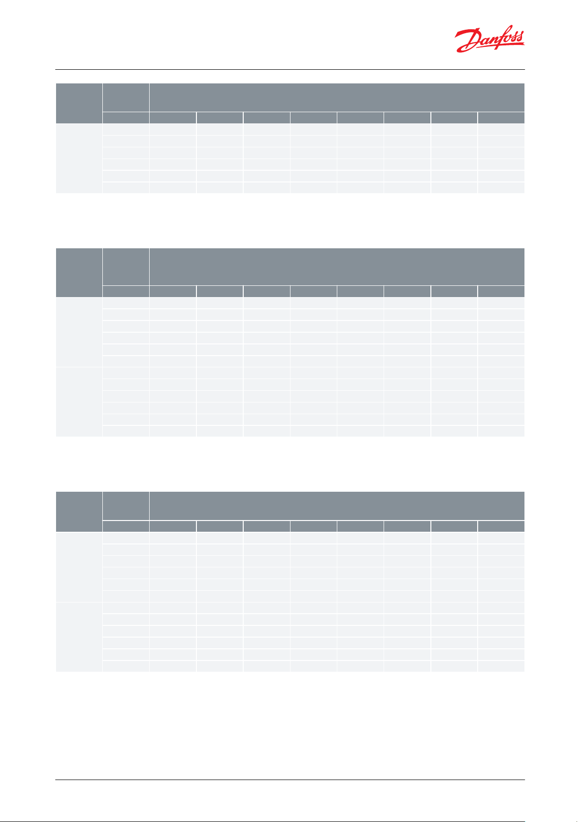
Capacity tables
Table 2: Regulator capacity Qe 1) [kW] with oset = 0.6 bar, R134a
© Danfoss | Climate Solutions | 2021.08 AI249086497299en-001001 | 4
Page 5
Type
Pressure drop
in regulator
∆p
Evaporating temperature t
e
[°C]
[bar]
-15
-10-505101520
KVP 28
KVP 35
0.1
4.1
4.6
5.2
5.8
6.5
7.2
7.9
8.7
0.2
5.5
6.3
7.2891011.1
12.2
0.3
6.5
7.5
8.5
9.6
10.81213.4
14.8
0.4
7.1
8.3
9.5
10.8
12.2
13.7
15.2
16.9
0.5
7.6
8.9
10.3
11.8
13.41516.8
18.6
0.6
7.9
9.41112.6
14.3
16.2
18.1
20.2
Type
Pressure drop
in regulator
∆p
Evaporating temperature t
e
[°C]
[bar]
-35
-30
-25
-20
-15
-10-50
KVP 12
KVP 15
KVP 22
0.1
1.5
1.7
1.9
2.2
2.5
2.733.4
0.222.3
2.733.4
3.8
4.3
4.7
0.3
2.4
2.8
3.2
3.6
4.1
4.6
5.1
5.7
0.4
2.6
3.1
3.5
4.1
4.6
5.2
5.9
6.5
0.5
2.8
3.3
3.9
4.4
5.1
5.7
6.5
7.2
0.6
2.9
3.5
4.1
4.7
5.4
6.277.8
KVP 28
KVP 35
0.133.4
3.9
4.4
4.9
5.5
6.1
6.8
0.244.7
5.3
6.1
6.8
7.7
8.5
9.5
0.3
4.7
5.5
6.4
7.2
8.2
9.2
10.3
11.5
0.4
5.2
6.1
7.1
8.2
9.3
10.5
11.7
13.1
0.5
5.5
6.6
7.7
8.9
10.2
11.51314.5
0.6
5.878.2
9.5
10.9
12.41415.7
Type
Pressure drop
in regulator
∆p
Evaporating temperature t
e
[°C]
[bar]
-25
-20
-15
-10-50
5
10
KVP 12
KVP 15
KVP 22
0.122.3
2.6
2.9
3.2
3.6
4
4.4
0.2
2.8
3.2
3.644.555.6
6.1
0.3
3.3
3.8
4.3
4.8
5.4
6.1
6.7
7.4
0.4
3.6
4.2
4.8
5.5
6.2
6.9
7.7
8.5
0.5
3.9
4.5
5.266.8
7.6
8.5
9.4
0.644.8
5.6
6.4
7.3
8.2
9.2
10.2
KVP 28
KVP 35
0.1
4.1
4.6
5.2
5.8
6.5
7.2
8
8.8
0.2
5.6
6.4
7.2
8.1
9.1
10.1
11.2
12.3
0.3
6.5
7.5
8.6
9.7
10.9
12.2
13.5
14.9
0.4
7.2
8.4
9.71112.4
13.8
15.4170.5
7.8
9.1
10.51213.6
15.2
17
18.8
0.6
8.1
9.6
11.2
12.8
14.6
16.4
18.4
20.4
Evaporator pressure regulator, type KVP
1
) The capacities are based on liquid temperature ahead of expansion valve tl = 25 °C regulator oset = 0.6 bar
Dry saturated gas ahead of regulator
Table 3: Regulator capacity Qe 1) [kW] with oset = 0.6 bar, R404A/R507
1
) The capacities are based on liquid temperature ahead of expansion valve tl = 25 °C regulator oset = 0.6 bar
Dry saturated gas ahead of regulator
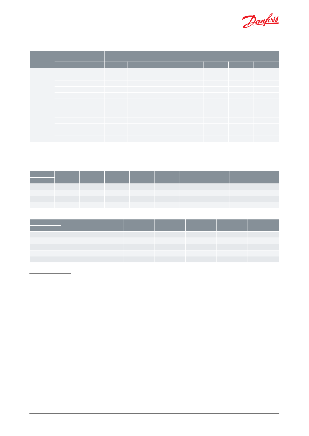
Table 4: Regulator capacity Qe 1) [kW] with oset = 0.6 bar, R407C
1
) The capacities are based on liquid temperature ahead of expansion valve tl = 25 °C regulator oset = 0.6 bar
Dry saturated gas ahead of regulator
© Danfoss | Climate Solutions | 2021.08 AI249086497299en-001001 | 5
Page 6
Type
Pressure drop in regulator
∆p
Evaporating temperature t
e
[°C]
[bar]
-25
-20
-15
-10-50
5
KVP 12
KVP 15
KVP 22
0.1
2.1
2.4
2.633.3
3.640.2
2.8
3.2
3.7
4.1
4.6
5.1
5.6
0.3
3.4
3.9
4.4
4.9
5.5
6.2
6.8
0.4
3.8
4.3
4.9
5.6
6.377.8
0.5
4
4.7
5.4
6.1
6.9
7.7
8.6
0.6
4.355.8
6.6
7.4
8.4
9.3
KVP 28
KVP 35
0.1
4.2
4.7
5.3
5.9
6.6
7.3
8.1
0.2
5.7
6.5
7.3
8.2
9.2
10.2
11.3
0.3
6.8
7.7
8.8
9.9
11.1
12.4
13.7
0.4
7.5
8.7
9.9
11.2
12.6
14.1
15.6
0.5
8.1
9.4
10.8
12.3
13.9
15.5
17.3
0.6
8.5
10.0
11.6
13.2
14.9
16.8
18.7
t
l
101520253035404550
[°C]
R134a
0.86
0.9
0.9511.06
1.12
1.19
1.28
1.37
R404A/R507
0.82
0.87
0.9311.08
1.17
1.29
1.43
1.61
R407C
0.86
0.9
0.9511.06
1.13
1.2
1.29
1.4
R448A
0.85
0.9
0.9411.06
1.13
1.22
1.32
1.44
Oset
0.2
0.4
0.6
0.811.2
1.4
[bar]
KVP 12
2.5
1.410.77
0.67
0.59
–
KVP 15
2.5
1.410.77
0.67
0.59
–
KVP 22
2.5
1.410.77
0.67
0.59
–
KVP 28–1.410.77
0.67
0.59
0.53
KVP 35–1.410.77
0.67
0.59
0.53
Evaporator pressure regulator, type KVP
Table 5: Regulator capacity Qe 1) [kW] with oset =0.6 bar, R448A
1
) The capacities are based on liquid temperature ahead of expansion valve tl = 25 °C regulator oset = 0.6 bar
Dry saturated gas ahead of regulator
Table 6: Correction factors for liquid temperature t
l
Table 7: Correction factors for oset
Valve selection
Example
When selecting the appropriate valve it may be necessary to convert the actual evaporator capacity using a
correction factor. This is required when your system conditions are dierent than the table conditions. The selection
is also dependant on the acceptable pressure drop across the valve.
The following example illustrates how this is done:
• Refrigerant: R134a
• Evaporator capacity: Qe = 4.2 kW
• Evaporating temperature: te = 5 °C ~ 2.5 bar
• Minimum evaporating temperature: 1.4 °C ~ 2.1 bar
• Liquid temperature ahead of expansion valve: tl = 30 °C
• Connection type: Solder
• Connection size:
5
⁄8 in.
Step 1
Determine the correction factor for liquid temperature tl ahead of expansion valve. From the Table 8: Correction
factors for liquid temperature tl a liquid temperature of 30 °C, R134a corresponds to a factor of 1.06.
© Danfoss | Climate Solutions | 2021.08 AI249086497299en-001001 | 6
Page 7
t
l
101520253035404550
[°C]
R134a
0.86
0.9
0.9511.06
1.12
1.19
1.28
1.37
R404A/R507
0.82
0.87
0.9311.08
1.17
1.29
1.43
1.61
R407C
0.86
0.9
0.9511.06
1.13
1.2
1.29
1.4
R448A
0.85
0.9
0.9411.06
1.13
1.22
1.32
1.44
Oset
0.2
0.4
0.6
0.811.2
1.4
[bar]
KVP 12
2.5
1.410.77
0.67
0.59
–
KVP 15
2.5
1.410.77
0.67
0.59
–
KVP 22
2.5
1.410.77
0.67
0.59
–
KVP 28–1.410.77
0.67
0.59
0.53
KVP 35–1.410.77
0.67
0.59
0.53
Evaporator pressure regulator, type KVP
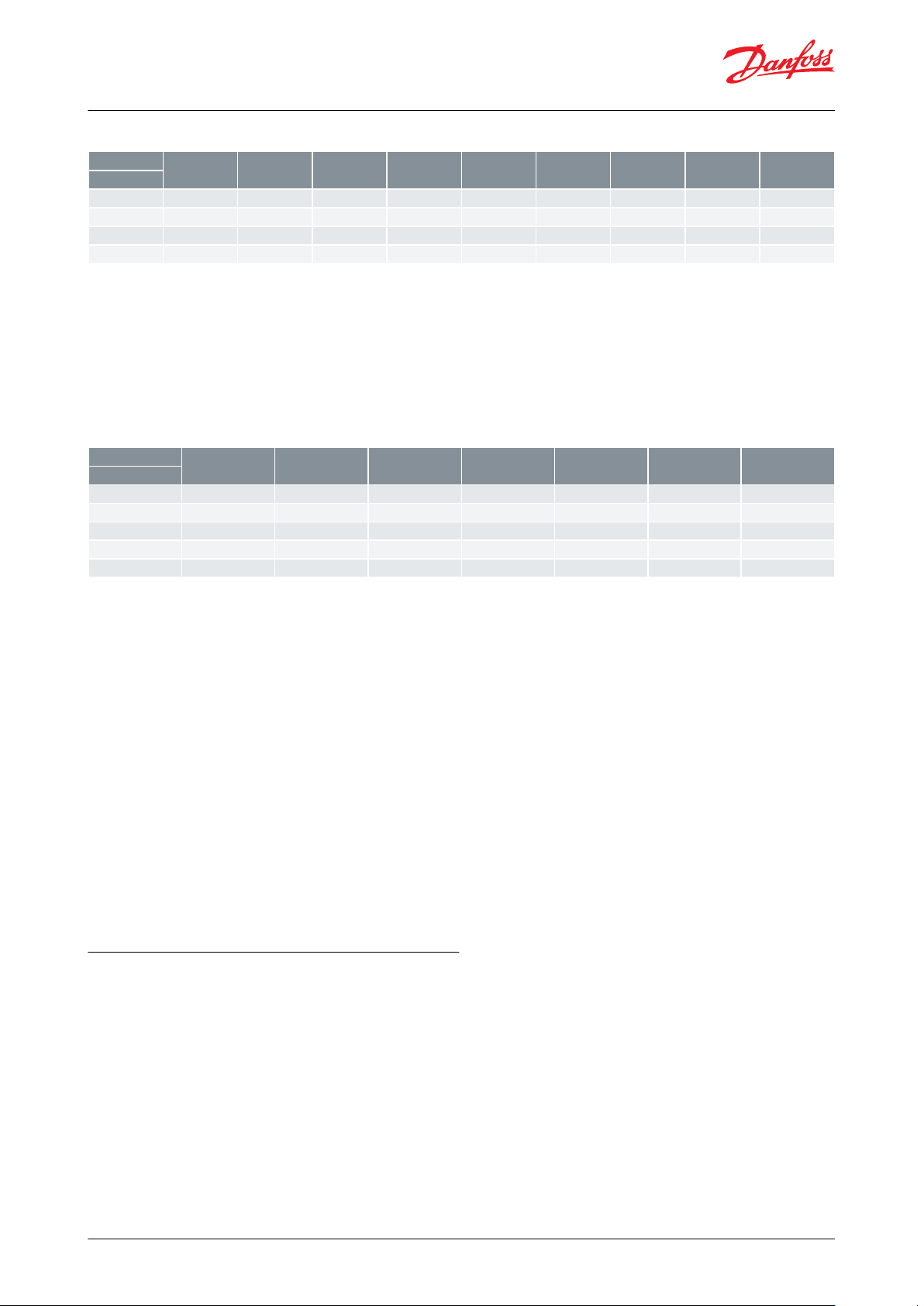
Table 8: Correction factors for liquid temperature t
l
Step 2
Determine the correction factor for the valve oset.
The oset is dened as the dierence between the design evaporating pressure and the minimum evaporating
pressure.
From the Table 9: Correction factors for oset, an oset of 0.4 bar (2.5 – 2.1) corresponds to a factor of 1.4.
Table 9: Correction factors for oset
Step 3
Corrected evaporator capacity is Qe = 1.06 × 1.4 × 4.2 = 6.2 kW
Step 4
Now select the appropriate capacity table (R134a) and choose the column for an
evaporating temperature of te = 5 °C.
Using the corrected evaporator capacity, select a valve that provides an equivalent or greater capacity at an
acceptable pressure drop. KVP 12, KVP 15, KVP 22 delivers 6.4 kW at a 0.6 bar pressure drop across the valve.
KVP 28, KVP 35 delivers 6.2 kW at a 0.1 bar pressure drop across the valve.
Based on the required connection size of 5⁄8 in., the KVP 15 is the proper selection for this example.
Step 5
KVP 15,
5
⁄8 in. solder connection: code no. 034L0029, see Table 11: Ordering for type KVP.
Valve selection based on capacity calculation
As for extended capacity calculations and valve selection based on capacities and refrigerants, please refer to
Coolselector®2. Rated and extended capacities are calculated with the Coolselector®2 calculation engine to ARI
standards with the ASEREP equations based on laboratory measurements of selected valves.
© Danfoss | Climate Solutions | 2021.08 AI249086497299en-001001 | 7
Page 8

Type
Connection
NV1
NV2H1H2H3B1B2C solder
øD
Net
weight
Flare
Solder ODF
[in.]
[mm]
[in.]
[mm]
[mm]
[mm]
[mm]
[mm]
[mm]
[mm]
[mm]
[mm]
[mm]
[Kg]
KVP 12
1⁄2121⁄2121919179996664411030
0.4
KVP 15
5⁄8165⁄8162424179996664411230
0.4
KVP 22--
7⁄8222424179996664411730
0.4
KVP 28--
11⁄8282424259
151
103
1054820431
KVP 35--
13⁄835--259
151
103
1054825431
Evaporator pressure regulator, type KVP
Dimensions and Weight
Figure 3: Dimensions for KVP
Table 10: Dimensions and Weight for KVP
© Danfoss | Climate Solutions | 2021.08 AI249086497299en-001001 | 8
Page 9
Type
Rated capacity
(1)
Flare connection
(2)
Code no.
Solder connection
Code no.
R134a
R404A/
R507
R407C
R448A
[in]
[mm]
[in]
[mm]
[in]
KVP 12
3.1
3.844.1
1⁄212034L0021
1⁄2–034L0023
3.1
3.844.1––––12034L0028
KVP 15
3.1
3.844.1
5⁄816034L0022
5⁄816034L0029
KVP 22
3.1
3.844.1–––7⁄822034L0025
KVP 28
6.3
7.7
8.1
8.2–––11⁄8–034L0026
6.3
7.7
8.1
8.2––––28034L0031
KVP 35
6.3
7.7
8.1
8.2–––13⁄835034L0032
Evaporator pressure regulator, type KVP
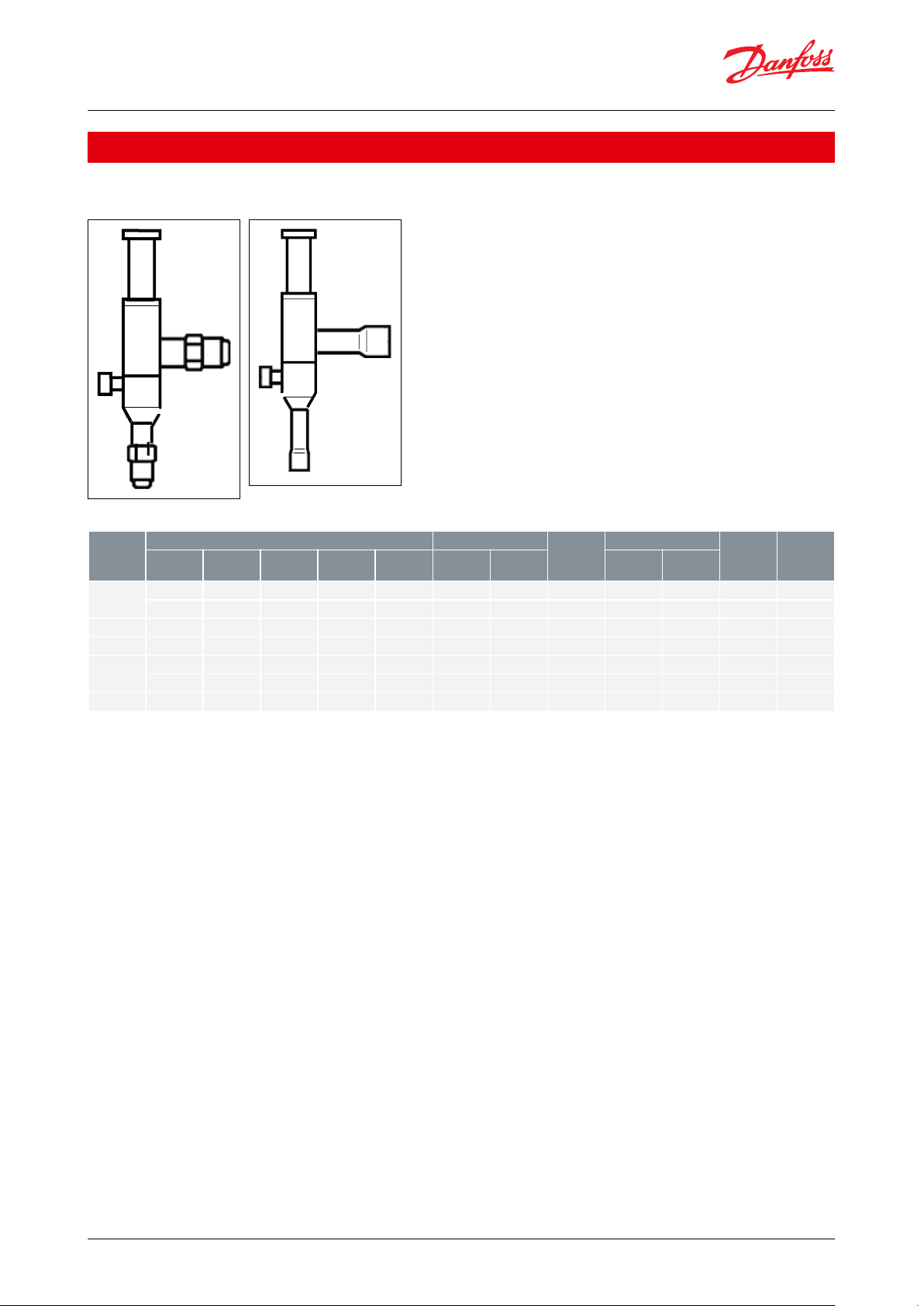
Ordering
Figure 4: Flare
connection
Figure 5: Solder
connection
Table 11: Ordering for type KVP
(1)
(1)
Rated capacity is the regulator capacity at
Rated capacity is the regulator capacity at
• evaporating temperature te = -10 °C
• evaporating temperature te = -10 °C
• condensing temperature tc = 30 °C
• condensing temperature tc = 30 °C
• pressure drop in regulator Δp = 0.2 bar oset = 0.6 bar
• pressure drop in regulator Δp = 0.2 bar oset = 0.6 bar
To select the product for other conditions or refrigerants, use Danfoss Coolselector®
To select the product for other conditions or refrigerants, use Danfoss Coolselector®
(2)
(2)
KVP supplied without are nuts. Separate are nuts can be supplied:
KVP supplied without are nuts. Separate are nuts can be supplied:
1
1
•
⁄2 in / 12 mm, code no. 011L1103
•
⁄2 in / 12 mm, code no. 011L1103
5
5
•
⁄8 in / 16 mm, code no. 011L1167
•
⁄8 in / 16 mm, code no. 011L1167
The connection dimensions chosen must not be too small, as gas velocities in excess of 40 m / s at the inlet of the
regulator can result in ow noise.
© Danfoss | Climate Solutions | 2021.08 AI249086497299en-001001 | 9
Page 10

Document name
Document type
Document topic
Approval authority
UL SA7200
Mechanical - Safety Certicate
-UL034R9541.AA
Manufacturers Declaration
China RoHS
Danfoss
034L9630.AA
Manufacturers Declaration
ATEX
Danfoss
Evaporator pressure regulator, type KVP
Certicates, declarations, and approvals
The list contains all certicates, declarations, and approvals for this product type. Individual code number may have
some or all of these approvals, and certain local approvals may not appear on the list.
Some approvals may change over time. You can check the most current status at danfoss.com or contact your local
Danfoss representative if you have any questions.
Table 12: Certicates, declarations, and approvals
© Danfoss | Climate Solutions | 2021.08 AI249086497299en-001001 | 10
Page 11
Online support
Danfoss oers a wide range of support along with our products, including digital product information, software,
mobile apps, and expert guidance. See the possibilities below.
The Danfoss Product Store
The Danfoss Product Store is your one-stop shop for everything product related—no matter where
you are in the world or what area of the cooling industry you work in. Get quick access to essential
information like product specs, code numbers, technical documentation, certications, accessories,
and more.
Start browsing at store.danfoss.com.
Find technical documentation
Find the technical documentation you need to get your project up and running. Get direct access to
our ocial collection of data sheets, certicates and declarations, manuals and guides, 3D models
and drawings, case stories, brochures, and much more.
Start searching now at www.danfoss.com/en/service-and-support/documentation.
Danfoss Learning
Danfoss Learning is a free online learning platform. It features courses and materials specically
designed to help engineers, installers, service technicians, and wholesalers better understand the
products, applications, industry topics, and trends that will help you do your job better.
Create your Danfoss Learning account for free at www.danfoss.com/en/service-and-support/learning.
Get local information and support
Local Danfoss websites are the main sources for help and information about our company and
products. Find product availability, get the latest regional news, or connect with a nearby expert—all
in your own language.
Find your local Danfoss website here: www.danfoss.com/en/choose-region.
Coolselector®2 - nd the best components for you HVAC/R system
Coolselector®2 makes it easy for engineers, consultants, and designers to nd and order the best
components for refrigeration and air conditioning systems. Run calculations based on your operating
conditions and then choose the best setup for your system design.
Download Coolselector®2 for free at coolselector.danfoss.com.
Any information, including, but not limited to information on selection of product, its application or use, product design, weight, dimensions, capacity or any other
technical data in product manuals, catalogues descriptions, advertisements, etc. and whether made available in writing, orally, electronically, online or via download,
shall be considered informative, and is only binding if and to the extent, explicit reference is made in a quotation or order conrmation. Danfoss cannot accept any
responsibility for possible errors in catalogues, brochures, videos and other material. Danfoss reserves the right to alter its products without notice. This also applies to
products ordered but not delivered provided that such alterations can be made without changes to form, t or function of the product. All trademarks in this material
are property of Danfoss A/S or Danfoss group companies. Danfoss and the Danfoss logo are trademarks of Danfoss A/S. All rights reserved.
© Danfoss | Climate Solutions | 2021.08 AI249086497299en-001001 | 11
 Loading...