

Page 1
DESCRIPTION
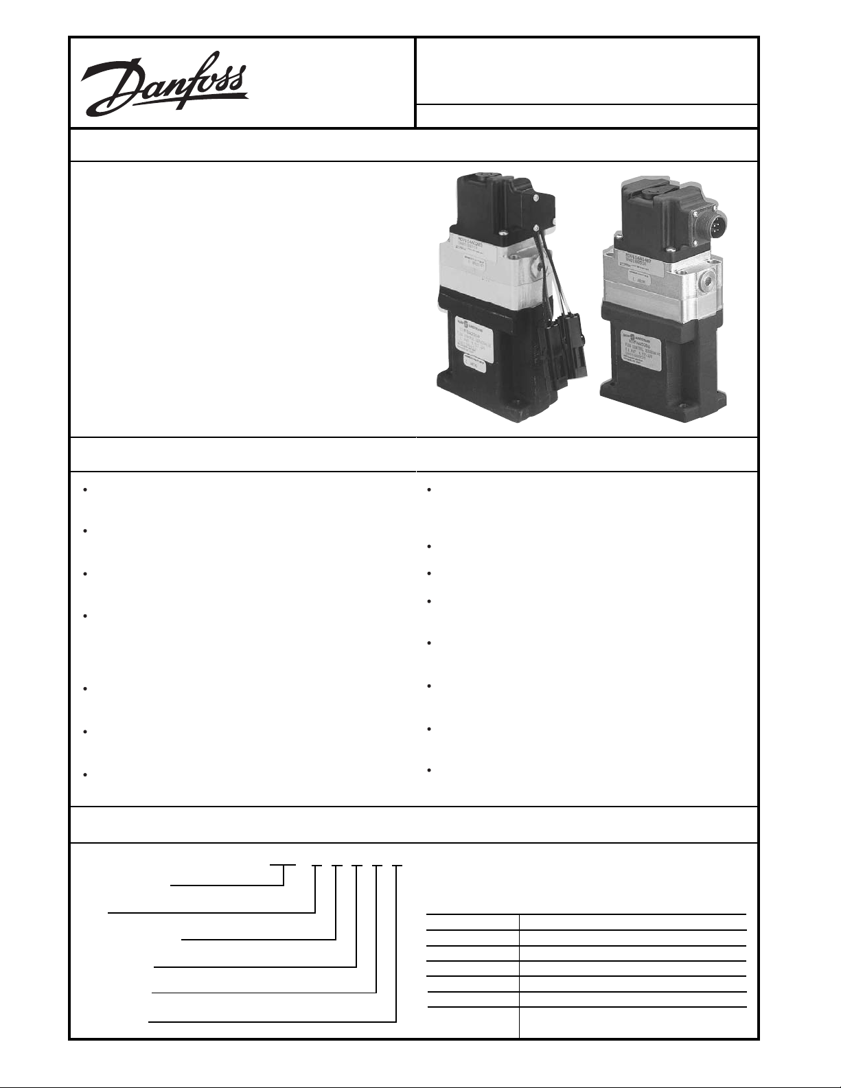
The KVF Flow Control Servovalve is a precision servovalve
that provides an output flow rate proportional to a low power
electrical input signal. It features a torque motor-actuated,
double-nozzle flapper pressure control pilot valve mated to a
pressure-actuated, spring-centered boost valve module of a
unique double-spool configuration.
The design of this servovalve does not require a centering
feedback spring and ball for spool position. The servovalve's
pilot stage is a stand-alone, closed loop pressure control
valve which uses internal hydraulic pressure reactions to
achieve its closed loop control characteristics.
This combination was selected to provide fabrication
economies resulting in true servovalve performance at
proportional valve pricing. The KVF Servovalve's steady
state/dynamic response characteristics are compatible with
industrial feedback control system applications.
FEATURES
KVF
Flow Control Servovalve (FCS)
BLN-95-9061-4 Issued: February 2004
Self-contained pressure feedback, eliminates requirement
for feedback spring and ball for spool position
ISO 4406 filtration rating of 18/15 (Nominal 10 micron
filtering provides dependable performance)
Standard manual operator assists with operation and
system diagnostics
Requires low power dc current to drive rated flow;
±20 mA, ±40 mA, ±100 mA, ±150 mA, or ±220 mA, are
standard options. The ±20 mA, can be driven directly
from PLC.
Does not require PWM drive for dither but is directly
compatible with other drives
4 to 20 mA version is configured such that 4 mA = 0 flow
and 20 mA = maximum flow
Unique two spool main body design allows for factory
adjustment of null pressures at each working port
Units available in standard line-to-line or overlapped
configuration in all flows from 1 1/4 gpm to 20 gpm at no
additional cost
Installation dimensions common to all servovalves
Pricing is independent of flow capability
Four connector option: MS, 2-pin WP, 4-pin WP, or 2-2
pin WP
Easily connected for unidirectional use from 2 1/2 gpm to
35 gpm at 1000 psi rating
Adaption maniflods available for conversion to other
valve patterns
Dual spool design provides added safety shut down if
contamination causes failure of either spool
Capability of separating control source from main stage
supply to accommodate high back pressure applications
ORDERING INFORMATION
KVF X X X X X
Device Identity
Rev
Supply Pressure
Flow Rating
% Lap Split
Pilot Stage
© Danfoss, 2013-09 BLN-95-9076-2 1
Ordering specifications for standard models.
DEVICE IDENTITY
The modle code for this device is KVF.
MODEL CODE SUPPLY PRESSURE
A 500 to 3000 psi
C 200 to 1000 psi
D 500 to 3000 psi with separate pilot drain
E 2500 to 3000 psi
F 500 to 3000 psi w/o cylinder port orifices
G 500 to 3000 psi w/o cylinder port orifices
and with pilot drain
Page 2
ORDERING INFORMATION (continued)
FLOW RATING
MODEL CODE FLOW RATING
1 1.25 gpm
2 2.5 gpm
5 5 gpm
6 10 gpm
7 15 gpm
8 20 gpm
9 20 gpm with 300 lb/in springs
PILOT STAGE
PILOT STAGE DEVICE NUMBER RATED CURRENT COIL(s) CONNECTOR TYPE SCALE FACTOR
01 * MCV116A3102 ±150 mA 23 ohms Packard 1.15 psid/mA
02 * MCV116A3101 ±150 mA 23 ohms MS 1.15 psid/mA
03 * MCV116A3204 ±220 mA 16/19 ohms Packard 0.78 psid/mA
05 * MCV116A1307 ±40 mA 69 ohms MS 4.2 psid/mA
06 MCV116A1407 ±40 mA 106 ohms MS 5.5 psid/mA
07 MCV116A1402 ±40 mA 106 ohms Packard 5.5 psid/mA
08 * MCV116A1302 ±40 mA 69 ohms Packard 4.2 psid/mA
09 MCV116A1501 ±20 mA 643 ohms MS 12.6 psid/mA
10 * MCV116A3203 ±220 mA 16/19 ohms Packard (2) 0.78 psid/mA
14 MCV116A1101 ±100 mA 23 ohms MS 2.4 psid/mA
15 MCV116A3201 ±220 mA 16/19 ohms MS 0.78 psid/mA
16 MCV116A1203 ±160 mA 16/19 ohms Packard (2) 1.47 psid/mA
17 MCV116A1201 ±160 mA 16/19 ohms MS 1.47 psid/mA
18 MCV116A1102 ±100 mA 23 ohms Packard 2.4 psid/mA
19 MCV116A1502 ±20 mA 643 ohms Packard 12.6 psid/mA
20 MCV116A3214 ±220 mA 16/19 ohms Deutsch 0.78 psid/mA
21 MCV116A3100 ±150 mA 23 ohms No connector 1.15 psid/mA
22 MCV116J1407 Special, contact Danfoss
23 MCV116A1214 ±160 mA 16/19 ohms Deutsch 1.47 psid/mA
24 MCV116A1315 ±40 mA 69 ohms No connector 4.1 psid/mA
25 MCV116A1216 ±160 mA 16/19 ohms Deutsch 1.47 psid/mA
* 1.25, 2.5, and 5.0 gpm only.
% LAP SPLIT
MODEL CODE % LAP SPLIT
0 Line-to-line 50%
1 Standard overlap, 50%
2 Standard overlap, 2%
3 Heavy overlap, 50%
4 Heavy overlap, 2%
1
% of supply pressure at C1 and C2 when servo valve
is at null.
1
TYPICAL APPLICATIONS
Air cargo loading
Motion simulators
Asphalt pavers
Saw setworks positioners
Concrete pavers
Manipulator arms / industrial robots
Milling machines
Soil stabilizers
Material mixing machinery
Synchronized knife carriage servodrives
Edger in feed board positioners
Paper mill machinery
Injection molding machinery
Platform leveling
Edge guide control machinery
Product testing machinery
Marine deck machinery
Rocket motor testing equipment
Oil exploration equipment
2
For steering applications,
contact Danfoss
BLN-95-9061-4
Page 3
TECHNICAL DATA
3
3
3
3
• Electric current in torque motor coil creates a magnetic
torque on armature
• Armature/flapper rotates about torsion pivot
• Flapper repositions towards one nozzle, which creates a
differential pressure between P1 and P2
• Each spool moves in the same direction opening the
supply )Ps) to output (C1 or C2) on one spool and the
output (C1 or C2) to return (PT) on the other spool
• Differential pressure between P1 and P2 causes the
spools to move against the centering springs until the
spring force balances with the differential pressure
• Control pressure (PC1 or PC2) reflected to the flapper
produces torque on the flapper in opposition to the
magnetic torque on the armature
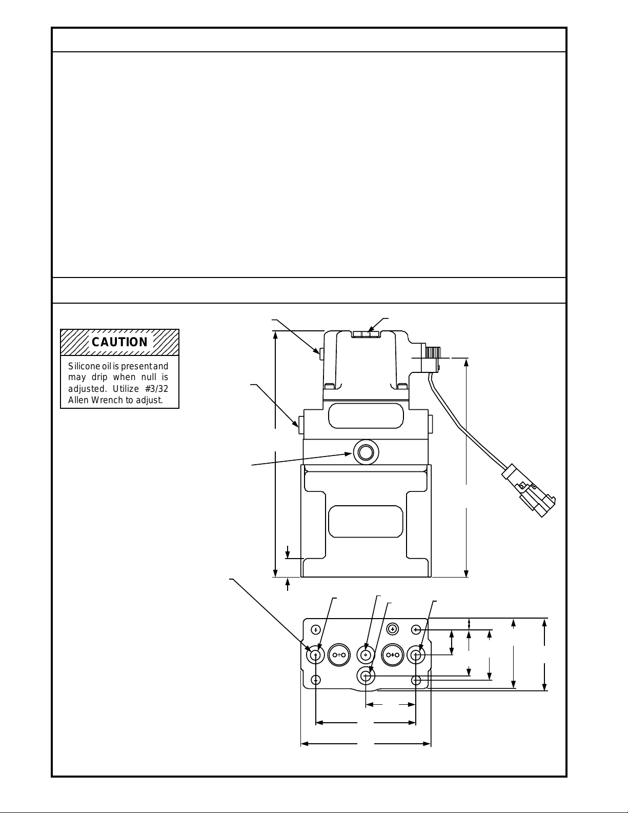
DIMENSIONS
234567890123456789012
234567890123456789012
234567890123456789012
CAUTION
234567890123456789012
NULL ADJUST ACCESS
• As the pressure torque on the flapper becomes equal to
the magnetic torque on the armature, the flapper moves
away from the closed nozzle to an equilibrium position
producing a steady-state control pressure (PC1 or PC2)
on the ends of each valve spool
• Each valve spool stops at a position where the control
pressure force on the end of each valve spool equals the
spring force on each valve spool
• Therefore, valve spool position is proportional to input
current and, with a constant pressure drop across the
spool meter-in and meter-out edges, the flow rate to the
load is proportional to spool position
MANUAL OPERATOR
Silicone oil is present and
may drip when null is
adjusted. Utilize #3/32
Allen Wrench to adjust.
3/8 O.D. TUBE
FITTING O-RING,
PORT PER SAE - J514
9/16 - 18 UNF (2 - PL)
PLUGS INSTALLED
EXTERNAL
PILOT DRAIN
ON "D" MODEL ONLY
.312 DIA
.566 O.D.
O-RING
(4-PL)
184,15
(7.32)
11,43
(.45)
C1
PT
PS
C2
19,05
(.75)
157,99
(6.22)
8,89
(.35)
34,93
(1.375)
38,1
(1.50)
53,09
(2.09)
55,37
(2.18)
BLN-95-9061-4
38,1
(1.50)
76,2
(3.00)
99,06
(3.90)
1428B
Dimensions of the KVF in Millimeters (Inches).
3
Page 4

INTERNAL WORKING SHEMATIC
PS
PT
ARMATURE
AIR GAP
PS
COIL
POLE
PIECE
PIVOT
PLATE
FLAPPER
NOZZLE
ORIFICE
PLATE
P1 P2
PERFORMANCE
RATED SUPPLY PRESSURE
3000 psi
FLOW RATINGS AT 1000 PSI VALVE DROP
1.25, 2.5, 5, 10, 15, 20 gpm
RATED INPUT SIGNAL
±20 mA dc, ±40 mA dc, ±100 mA dc,
±150 mA dc, ±220 mA dc,
FLUID
Petroleum base
P1
PS
P2
P1
PS
P2
C2C1
1289C
LINEARITY
< 5% rated signal
SYMMETRY
5% (maximum) each direction
PRESSURE RISE (BLOCKED OUTPUT PORTS)
> 80% Ps at 4% rated signal (except for 2, 3, 4 lap)
TYPICAL FREQUENCY RESPONSE
(1000 PSI VALVE DROP)
90° phase lag frequency > 30 Hz
-3 dB amplitude ratio frequency > 30 Hz
INTERNAL LEAKAGE (PILOT and BOOST STAGES)
< 1.0 gpm (< .5 gpm available on special models where
leakage requirements are primary)
THRESHOLD
< 1% rated signal (except for 2, 3, and 4 lap)
HYSTERESIS
< ±5% rated signal
RETURN PRESSURE
Atmospheric to 200 psi ("D" model provides separate
return for higher return ratings)
FLUID/AIR RATED TEMPERATURE RANGE
-20° F to 200° F
RECOMMENDED SYSTEM FILTRATION
10 micron (in-line pressure filter)
4
BLN-95-9061-4
Page 5

PERFORMANCE (continued)
ELECTRICAL CONNECTION/PHASING
Positive voltage at pin B or D with negative voltage at
pin A
Produces flow out port C1
ENVIRONMENTAL
TEMPERATURE NULL SHIFT
< 5% rated signal over rated fluid/air temperature range
PRESSURE NULL SHIFT
< 4% rated signal, 500 psi to rated supply pressure
VIBRATION
5 Hz to 2000 Hz freguency spectrum
1 g to 46 g's acceleration (varies with frequency)
FLOW SIZING FORMULAE
i
PS - ∆P
QV = Q
Q
Q
• •
r
( )
i
r
is the valve flow at an operating point
V
is the rated flow at ir and ∆PV = 1000 psi)
r
i is the operating current
i
is the rated current
r
P
is the supply pressure to the valve
S
∆P
is the load pressure between the valve's control ports (P
L
∆P
is the valve pressure drop across the valve (PS -
V
L
1000
SPACE/WEIGHT
7.25 inch high x 2.18 inch wide x 3.16 inch long; 6.6 lbs.
SHOCK
50 g's (11 millisecond duration) three mutually
perpendicular axes
SAND/DUST/HUMIDITY
Per MIL-STD-810 current issue
)
C1 - PC2
∆
P
)
L
Note:
(1) The rated flow occurs at:
∆P
V
= PS
3 (the maximum power transfer to load)
/
(2) Higher flow rates will incur some saturation
(3) The tank pressure is assumed to be zero (otherwise, substitute P
RATED SIGNAL FLOW VS.
PRESSURE DROP
LOAD FLOW VS.
LOAD PRESSURE
40
30
20
15
10
7
5
LOAD FLOW GPM
3
2
1.5
1.0
200 300 500 1000 2000 3000
20 gpm size
15 gpm size
10 gpm size
5 gpm size
2.5 gpm size
1.25 gpm size
VALVE PRESSURE DROP
PSI
S -
P
for PS )
t
- 100%
- 50%
- 75%
+100
LOAD FLOW %
-20 -40 -60 -80-100
- 25%
+80
+60
+40
+20
0
-20
-40
-60
-80
+ 75%
+ 50%
+ 25%
+20 +40
+ 100%
+80 +100
+60
LOAD PRESSURE
DROP % SUPPLY
BLN-95-9061-4
2033
-100
2034
5
Page 6

ADJUSTMENTS
The Servovalve is adjustable when re-centering of the output levels is required. The following steps are recommended while
referring to the Servovalve drawing (see drawing below). Required tools: one large slotted screw driver & one 3/32 internal
hex wrench
1. Locate the neutral adjustment access point. Using the slotted screw driver remove the access screw. See Caution # 1
2. See Caution # 2 Insert the hex wrench a short distance into the access opening and engage the adjustment setscrew.
3. Some applications require observing the system load while adjusting the servovalve and some require observing an
electrical deviation meter which measures closed loop feedback errors while adjusting the load. Adjustments are make
by turning the hex wrench very slowly either CW or CCW. Most adjustments require less than 1/3 turn from the starting
point to re-center the servovalve to achieve the desired results.
4. Upon completion ensure that the access screw is reinstalled. See Caution #3.
Caution # 1 Once the access screw is removed a small amount of silicone fluid may leak form this opening; the amount of
leakage depends on the valve orientation (see figure 1) in reference to gravity. Ensure that the screw is replaced once the
re-centering is completed
Caution # 2 To adjust neutral requires operating the hydraulic system; therefore, prior to the actual adjustment, take the
necessary safety precautions, such as having unnecessary personnel stand away form the machine as the system load will
likely move.
Caution # 3, A small amount of silicone oil leakage is acceptable (approximately 25 % of the total 45 cubic centimeters). If
excessive silicone oil is lost, restore the fluid using silicone oil replacing kit K21436 for models MCV113 & KVF. For models
MCV103, use kit K21435. Do not reuse any silicone oil that leaks from the cover due to the possibility of contamination.
NEUTRAL
ADJUSTMENT
ACCESS
ADJUSTMENT
NEUTRAL
SETSCREW
MANUAL OPERATOR
MAXIMUM/MINIMUM
OIL LEVEL
SILICONE OIL
LEVEL
SERVOVALVE
2100
6
BLN-95-9061-4
Page 7

SERVOVALVE (KVFXXXXXX) O-RING REPLACEMENT
Material
Nitrile
Pilot Stage Bottom
Viton
Viton
Viton
Viton
2
75 ± 5
75 ± 5
75 ± 5
90 ± 5
70 ± 5
Durometer
1
2
.070
.070
.070
.070
Width
.070
Boost Stage Top
2104
Boost Stage
3
.556
O.D.
.504
Dimensions
I.D.
.426 ± .005
.364 ± .005
6
Qty
6
K00830
K00829
Part Number
1
2
Item
.691
.504
.551 ± .005
.364 ± .005
2
1
K00832
K08493
3
4
.348
.208 ± .005
1
K07006
5
1
4
2
351
BLN-95-9061-4
Pilot Stage
Orifice
7
Boost
Page 8

Servovalve Manifold Options
Use this drawing and the chart listed below to
determine servovalve manifold mounting.
Top View Side View
DB
E
A
Danfoss Dimensions in Inches (Millimeters)
Part Number
K02099 3.75 2.60 1.23 1.50 3.00 0.219
Pilot Pressure Plate (95,25) (66,04) (31,24) (38,1) (76,2) (5,56)
Separate PCP Supply & Tank
K02100 3.75 2.60 1.23 1.50 3.00 0.219
Pilot Pressure Plate (95,25) (66,04) (31,24) (38,1) (76,2) (5,56)
Separate Supply to PCP
K29385 4.00 3.14 1.14 1.50 3.00 .0285
Blanking Plate (101,6) (80,0) (29,05) (38,1) (76,2) (7,26)
KK03501 4.00 2.25 1.00 NA NA NA
D01 Porting Adapter Plate (101,6) (57,15) (25,4)
KK03502 4.25 2.50 1.00 NA NA NA
D02 Porting Adapter Plate (107,95) (63,5) (25,4)
KK03503 4.00 2.25 0.50 NA NA NA
0.625 Dia. Port Circle Adapter Plate (101,6) (57,15) (12,7)
KK03504 3.90 2.00 0.75 NA NA NA
0.780 Dia. Port Circle Adapter Plate (99,06) (50,8) (19,05)
KK03505 4.25±0.06 3.25±0.03 0.875 NA NA NA
0.875 Dia. Port Circle Adapter Plate (107,95) (82,55) (22,23)
KK03506 4.00 2.00 0.75 NA NA NA
KVF to V7059 Adapter Plate (101,6) (50,8) (19,05)
KK03508 8.50 5.00 2.00 4.134 7.556 0.335
3-Valve Manifold (215,9) (127,0) (50,8) (105,0) (191,92) (8,51)
KK03509 5.00 3.00 1.00 2.24 4.24 0.281
Single Valve Manifold (127,0) (76,2) (25,4) (56,9) (107,7) (7,14)
KK03510 6.00 5.00 2.00 4.134 5.056 0.335
2-Valve Manifold (152,4) (127,0) (50,8) (105,0) (128,42) (8,51)
KK03511 11.00 5.00 2.00 4.11 10.06 0.335
4-Valve Manifold (279,4) (127,0) (50,8) (104,39) (255,52) (8,51)
KK03512 16.00 5.00 2.00 4.11 15.06 0.335
6-Valve Manifold (406,4) (127,0) (50,8) (104,39) (382,52) (8,51)
SAE Fittings on Sides
KK03513 5.00 3.00 1.50 2.50 4.50 0.281
Single Valve Manifold (127,0) (76,2) (38,1) (63,5) (114,3) (7,14)
SAE Fittings on Bottom
F
A B C D E F
C
2103
8
BLN-95-9061-4
Page 9

CUSTOMER SERVICE
NORTH AMERICA
ORDER FROM
Danfoss (US) Company
Customer Service Department
3500 Annapolis Lane North
Minneapolis, Minnesota 55447
Phone: (763) 509-2084
Fax: (763) 559-0108
DEVICE REPAIR
For devices in need of repair or evaluation, include a
description of the problem and what work you believe
needs to be done, along with your name, address and
telephone number.
RETURN TO
Danfoss (US) Company
Return Goods Department
3500 Annapolis Lane North
Minneapolis, Minnesota 55447
EUROPE
ORDER FROM
Danfoss (Neumünster) GmbH& Co.
Order Entry Department
Krokamp 35
Postfach 2460
D-24531 Neumünster
Germany
Phone: +49 4321 871-0
Fax: +49 4321 871-284
BLN-95-9061-4
9
 Loading...