

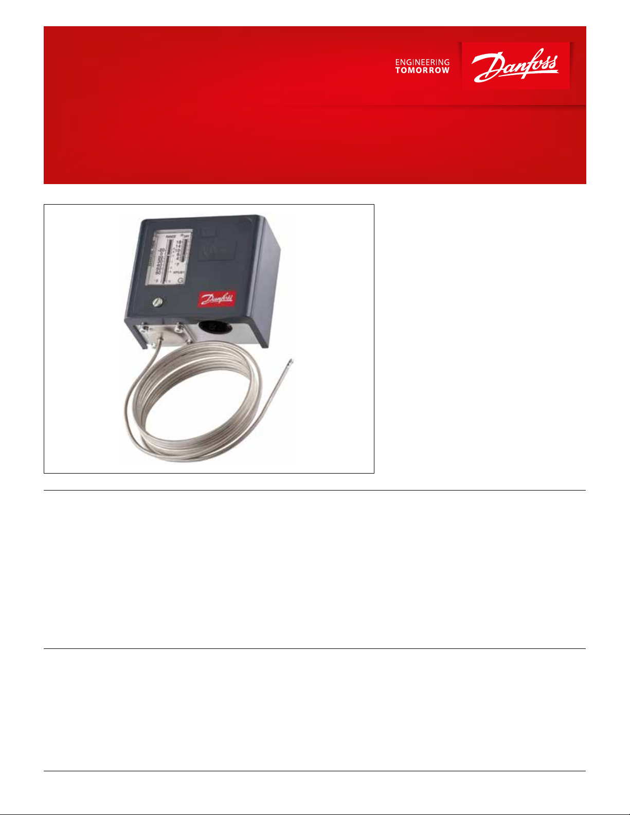
Data sheet
Thermostat
KPU
The KPU Thermostats are temperature controlled
electrical switches, which are applied for regulation
and safety monitoring of refrigeration and air
conditioning systems.
KPU sensors are available with vapor charge or
with adsorption charge. The Thermostats with
adsorption charge are widely used to give frost
protection, while vapor charged sensors are used
where small dierential is required.
All KPU Thermostats have a single pole double
throw (SPDT) contact system. Theposition of the
switch depends on the thermostat setting and the
bulb temperature.
Features
Approvals
© Danfoss | DCS (jmn) | 2016.08 DKRCC.PD.CA0.F6.22 | 520H11320 | 1
• Wide temperature regulating range allows use in
low, medium, and high temperature refrigeration
application and air-conditioningsystems
• Snap-action electrical contacts minimize chatter,
bounce and wear, and ensure long-term electrical
and mechanical reliability
• Fingertip manual trip feature allows contact
function testing without tools
• Easily replaces other manufacturers’ thermostats
• Ultra-short bounce time
UL listed for USA and Canada, le E31024
• Long operating lifetime
• Vibration and shock resistant
• SPDT switch allows NC or NO function option as
well as alarm capability
• Automatic and manual reset versions available
Data sheet | Thermostat, KPU
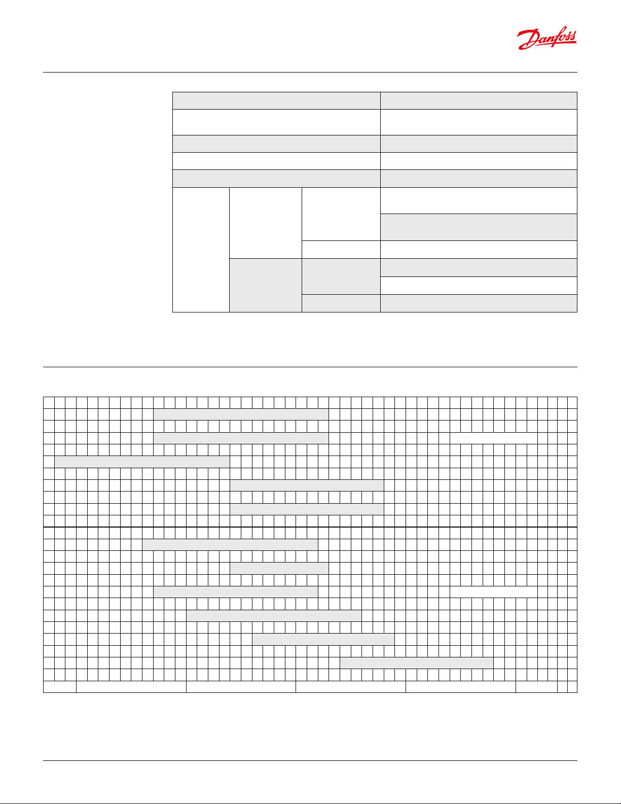
Technical data
Regulating ranges in [°F]
Ambient temperature -40 – 122 °F, 175 °F up to 2 hours
Cable entry
⁄ in cable entry for ½ in male pipe thread connection
(conduit boss)
Maximum wire dimension 10 AWG
Enclosure ~NEMA 1
Switch SPDT – single pole double throw
FLA = 24 A at 120 V AC
24 A at 240 V AC
NAM rating
Alternating current
1
) = 144 A at 120 V AC
LRA
144 A at 240 V AC
Contact load
Direct current 12 W pilot duty at 240 V DC
AC1: 16 A, 400 VA
European rating
(acc. to EN 60947)
Alternating current
AC3: 16 A, 400 VA
Direct current DC13: 12 W, 220 V control current
1)
LRA is rated for make only
KPU 61
KPU 62 (room sensor) Vapor charge
KPU 63
KPU 68 (room sensor)
KPU 69
KPU 62
KPU 71
KPU 73 Adsorption charge
KP U 74
KPU 75
KPU 77
-50 0 50 100 150
© Danfoss | DCS (jmn) | 2016.082 | 520H11320 | DKRCC.PD.CA0.F6.22
Data sheet | Thermostat, KPU
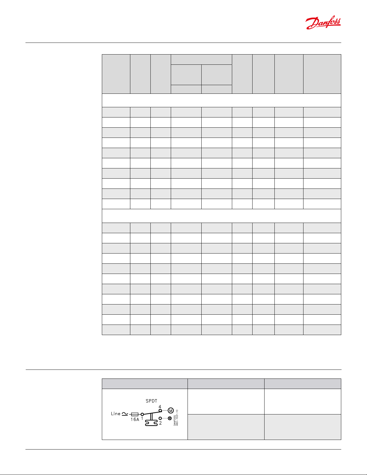
Ordering
Typ e
Bulb
type
Range
Dierential
at lowest
temperature
setting
at highest
temperature
setting
Max.
bulb
temp.
Reset
function
Capillary
tube length
Code no.
[°F] [°F] [°F] [°F] [in]
Vapour 1)
KPU 61 A -20 – 60 10 – 40 2.5 – 13 250 auto. 80 060L5201
KPU 61 B -20 – 60 10 – 40 2.5 – 13 250 auto. 80 060L5203
3
KPU 61B B -20 – 60 fix e d 11 fixed 3.5 250 man.
KPU 61B B -20 – 60 fix e d 11 fixed 3.5 250 man.
) 80 060L5204
3
) 200 060L5205
KPU 62 C1 -20 – 60 10 – 40 2.5 – 13 250 auto. room sensor 060L5206
4
KPU 61 B -20 – 60 10 – 40 2.5 – 13 250 auto.
) 80 060L5210
KPU 63 A -60 – 15 18 – 125 5 – 15 250 auto. 80 060L5213
KPU 63 B -60 – 15 18 – 125 5 – 15 250 auto. 80 06 0L5214
KPU 68 C1 25 – 95 8 – 45 3 – 13 250 auto. room sensor 060 L5215
KPU 69 B 25 – 95 8 – 45 3 – 13 250 auto. 80 060 L5217
Adsorption 2)
KPU 62 C2 -20 – 60 9 – 36 3 – 14 175 auto. 4) room sensor 060L5207
Contact system
KPU 73 E3 -15 – 60 6.5 – 32 5 – 50 175 auto. 80 060L5208
KPU 73 E1 -15 – 60 22 – 125 15 – 45 175 auto. 80 060L5209
3
KPU 73B E3 -15 – 60 fixed 6 fixed 6 175 man.
) 80 060 L52 11
KPU 73 D -15 – 60 6 – 35 5 – 32 175 auto. 80 060L 5212
KPU 71 E2 25 – 70 5.5 – 18 4 – 16 175 auto. 80 06 0L5218
3
KPU 71B E2 25 – 70 fixed 5 fixed 5 175 man.
) 80 060L 5216
KP U 74 E1 0 – 80 9 – 35 9 – 35 175 auto. 80 06 0L5219
3
KP U 74 B E1 0 – 80 fixed 10 fi xe d 10 175 man.
) 80 060L5220
KPU 75 F 30 – 95 6 – 29 4.5 – 21.5 230 auto. 80 06 0L 5221
KPU 77 E3 60 – 140 6 – 18 6.3 – 18 265 auto. 80 060L5223
1)
Bulb must be installed in colder position than thermostat
housing and capillary tube.
2
) Bulb can be placed warmer or colder than thermostat housing
and capillary tube, but variations from 70 °F
ambienttemperature will inuence the scale accuracy.
3
) Manual minimum reset. Marked with letter B. Fixed dierential.
These controls have no hand knob.
4
) With manual switch and top plate.
Switch type – singlepoledoublethrow Switch action Applicaton
1. Terminals 1 – 4 close high and
open low
Terminals 1 – 2 can be used as
1. Low temperature cut-out
low temperature alarm
2. Terminals 1 – 2 open high and
close low
Terminals 1 – 4 can be used as
2. High temperature cut-out
high temperature alarm
© Danfoss | DCS (jmn) | 2016.08 DKRCC.PD.CA0.F6.22 | 520H11320 | 3

Data sheet | Thermostat, KPU
Design / Function
1. Temperature setting spindle
2. Dierential setting spindle
3. Main spring
4. Dierential spring
5. Bellows
6. Capillary tube
7. Main arm
8. Switch
9. Cable entry
11. Temperature sensor
12. Setting knob
13. Dierential setting screw
14. Control terminals
15. Ground terminal
16. Contact housing
Key sketch of KPU Thermostat KPU Thermostat without front cover
Switches in KPU Thermostats have a snap-action
function, triggered when cut-in or cut-out
temperature is reached.
Snap-action creates anumber of advantages:
• High contact load capability
• Ultra-short bounce time
• Long mechanical and electrical life
• High resistance to pulsation and vibration
• Vibration resistance up to 4 g in range 0 – 1000 Hz
• Long mechanical and electrical service life
© Danfoss | DCS (jmn) | 2016.08 DKRCC.PD.CA0.F6.22 | 520H11320 | 4

Data sheet | Thermostat, KPU
Terminology Set point
A predetermined value to which a thermostat is
adjusted and at which it performs its
intendedfunction.
Dierential
The dierential is the dierence between the cutin
and cut-out temperatures. The dierential is
necessary for satisfactory automatic operation of
the controlled system.
Mechanical dierential (intrinsic dierential)
The mechanical dierential is the dierential set by
the dierential spindle.
Snap function
A specic contact force is maintained until snap is
initiated. The time over which contact force reaches
zero is a few milliseconds; therefore, contact
bounce due to vibration, for example, cannot occur
at cut-out. The snap-action contact system will
continue to function even when micro-welds are
created between the contacts during cut-in. The
force created to separate the contacts is strong
enough to instantly shear o all contact surface
welds that may have been created by cut-in action.
These design features ensure that the cut-out
setting of the KPU thermostat remains highly
accurate and completely independent of the
magnitude of the current load.
Reset
1. Manual reset:
A unit with manual reset can only be restored to
operational mode by activating the external reset
button.
On min. reset units the set value is equal to the
cut-out value for falling temperature. On max. reset
units the set value is equal to cut-out value for
rising temperature.
2. Automatic reset:
A unit with automatic reset is restored
tooperational mode automatically.
FLA – Motor Full Load Amperes
FLA is the largest current that a motor or other
device is designed to carry at rated voltage and
other specic conditions. Also often called current
at rated conditions.
LRA – Locked Rotor Amperes
LRA is the largest current that the motor is designed
to carry with shaft or rotor immobilized.
Setting and resets Thermostats with automatic reset
Set the cut-in temperature on the “RANGE” scale. Set
the dierential on the “DIFF” scale. Thecontrolled
system will start at the temperature set on the
RANGE scale and will be stopped when the
temperature falls the number of degrees set on the
DIFF scale.
Please note that the dierential scale is only
areference. The exact value of distances on thescale
depends on where in its range thecontrol cut-in is
set. Use the dierential scale asaguide, and if precise
function is required, establish the dierential setting
by comparing function with an accurate
thermometer in thecontrolled zone. If the
compressor does not stop at the desired low
temperature, check thedierential to ensure that it is
not set at too high avalue.
The thermostat automatically resets and
thecompressor starts once the temperature
risesabove the range scale setting.
Thermostats with manual minimum reset
Set the cut-out temperature on the range scale.
The dierential is xed.
Restart the compressor by pressing the reset
button after the temperature of the sensor rises to
a value equal to the range scale setting plus the
xed dierential.
Thermostats with manual maximum reset
Set the cut-out temperature on the range scale. The
dierential is xed.
Restart the compressor by pressing the reset button
after the temperature of the sensor falls toa value
equal to the range scale setting minus thexed
dierential.
© Danfoss | DCS (jmn) | 2016.08 DKRCC.PD.CA0.F6.22 | 520H11320 | 5

Data sheet | Thermostat, KPU
Charges
1. Vapor charge 2. Adsorption charge
Bellows
Capillary tube
Sensor
The sensor contains saturated vapor with
asmallquantity of liquid. When temperature rises,
liquidevaporates, and pressure inside
thesensorincreases.
After all of the liquid has evaporated, additional
heat results in only a small pressure rise inside the
element. Vapor charges are appropriate for low
temperature applications and others where the
bellows must be protected from deformation by
As long as the sensor is the coldest part of the
thermostat, ambient temperature has no eect on
regulating accuracy.
Sensors with adsorption charges contain
asuperheated gas together with a solid having
alarge adsorption surface. The sensor can be
placed in zones that are warmer or colder than the
control housing and capillary tube, but variations
of more than 70 °F may inuence scaleaccuracy.
ambient temperature.
The sensing element must be colder than the
bellows at all times so that condensation of
evaporated uid occurs in the element only, and
not in the bellows.
Bellows
Capillary tube
Sensor
Dimensions of KPU
withoutcapillary tube
All thermostats are supplied with universal
mountingbracket and mounting screws
asstandardaccessory.
Approximate weight of the bracket and mounting
screws: 0.615 lb
Net weight of KPU without capillary tube: ~ 0.77 lb
Net weight of 80 in capillary tube: ~ 0.17 lb
Net weight of 200 in capillary tube: ~ 0.43 lb
© Danfoss | DCS (jmn) | 2016.08 DKRCC.PD.CA0.F6.22 | 520H11320 | 6

Charges
KPU 61
KPU 63
Vapor charge
KPU 61
KPU 69
Vapor charge
KPU 62
KPU 68
Vapor charge
KPU 62
Adsorption charge
KPU 73
Adsorption charge
A
B
C
D
Straight capillary tube
Sensing length: 15 in
a = 3 1/8 in
Remote air coil
a = ⁄ in
b = 2 ¾ in
Room sensor C1
a = 1 ½ in
b = 1 ¼ in
Room sensor C2
a = 1 in
b = 3 in
Double contact remote bulb
a = ⁄ in
b = 3 ⁄ in
NOTE!
Can not be used in sensor pocket!
Remote bulb
KPU 73, KPU 74
Adsorption charge
KPU 71, KPU 75
Adsorption charge
KPU 73, KPU 77
Adsorption charge
KPU 75
Adsorption charge
E
F
E1
a = ¼ in
b = 3 ¾ in
E2
a = ⁄ in
b = 4 ½ in
E3
a = ⁄ in
b = 3 ⁄ in
Remote duct coil
a = 1 in
b = 3 ⁄ in
© Danfoss | DCS (jmn) | 2016.08 DKRCC.PD.CA0.F6.22 | 520H11320 | 7
 Loading...