

Data sheet
Data sheet
APP Pumps
APP pumps
APP 53 / APP 65 / APP 78 / APP 86 / APP 92
APP 53-86
hpp.danfoss.com
ro-solutions.com

Data sheet | APP 53-92 Pumps
Table of Contents
1. Introduction ............................................................................3
2. Benets.................................................................................3
3. Application examples ...................................................................3
4 Technical data ..........................................................................4
4.1 APP 53-92...............................................................................4
5. Performance curves.....................................................................6
5.1 APP 53 ow at dierent rpm.............................................................6
5.2 APP 65 ow at dierent rpm.............................................................7
5.3 APP 78 ow at dierent rpm.............................................................8
5.3 APP 86 ow at dierent rpm.............................................................9
5.4 APP 92 ow at dierent rpm............................................................10
6. Flushing valve curves ..................................................................11
6.1 APP 53-92 integrated ushing valve ....................................................11
7. Motor requirements....................................................................11
7.1 Calculation factor at 60 barg / 870 psig for APP 53-92....................................11
8. Temperature and corrosion.............................................................12
8.1 Operation..............................................................................12
9. Installation.............................................................................12
9.1 Filtration...............................................................................13
9.2 RO system with direct supply: ..........................................................13
10. Dimensions and connections...........................................................15
10.1 APP 53.................................................................................15
10.2 APP 65 - 92.............................................................................16
10.3 APP 53-92 with IE3 motor, IEC 315S - 4 ..................................................18
10.4 APP 53-92 with IE3 motor, IEC 315M - 4..................................................18
10.5 APP 53-92 with IE3 motor, IEC 315L 1-4 .................................................19
10.6 APP 53-92 with IE3 motor, IEC 315L 2 - 4 ................................................19
11. Pump connections .....................................................................20
11.1 APP 53 - 92.............................................................................20
12. VCM 3” Victaulic........................................................................21
12.1 Technical data .........................................................................21
12.2 Flow versus pressure ...................................................................22
13. Accessories ............................................................................23
14. Service and warranty...................................................................23
2 | © Danfoss | DCS (im) | 2021.12
AI167386503010en-001301
Data sheet | APP 53-92 Pumps
1. Introduction
The Danfoss range of APP high-pressure pumps
is designed according to EN 809 for use in RO
applications with low viscosity and corrosive
uids such as sea water.
Danfoss APP pumps are positive displacement
pumps with axial pistons that move a xed
amount of water in each cycle. Flow is proportional to the number of input shaft revolutions
(rpm).
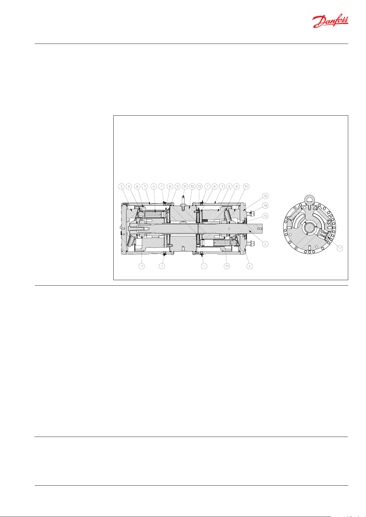
1 Housing
2 Shaft
3 Swash plate (non drive end)
4 Retainer plate
5 Piston
6 Cylinder barrel
7 Bleeding / drain plug
8 Valve plate
9 Port plate (non drive end)
Unlike centrifugal pumps, they produce the same
ow at a given speed no matter what the
discharge pressure.
The sectional drawing below illustrates the main
components of the APP 53-92 pump range.
10 Center ange
11 Spring cartridge
12 Eye bolt
13 Port plate (drive end)
14 Swash plate (drive end)
15 Shaft seal
16 Motor ange
17 Flushing valve
18 Tail stock screws
2. Benets
3. Application examples Danfoss APP pumps are built into a broad range
• Zero risk of lubricant contamination:
- Oil lubricants are replaced with the
pumped medium, water, so there is no
contamination risk from the pump.
• Low maintenance costs:
- Ecient design and all-stainless steel
construction ensure exceptionally long
life. When Danfoss specications are
met, service intervals of 8,000 hours can
be expected. Service is easy, and can be
carried out on-site due to the simple
design and few parts.
• Low energy costs:
- The highly ecient axial piston design
provides the lowest energy
consumption of any comparable pump
on the market.
• Easy installation:
- The most compact and lightest design
available.
- The pump can be installed horizon-
tally in dierent positions rotating it
around the shaft (see section 10 for
example).
of RO desalination plants around the world:
• Containerized solutions for hotels, resorts
and residences on islands and in coastal
regions
No pulsation dampeners necessary due
to extremely low pressure pulsation.
- Powered directly by electric motors or
combustion engines (with special
coupling).
- All pumps are supplied with an
integrated ushing valve that allows the
uid to ow from inlet to the outlet,
when the pump is not running.
• High reliability:
- All parts are made of high corrosion
resistant materials e.g. Duplex
(EN1.4462/ UNS S31803) and
Super Duplex (EN1.4410/UNS S32750)
stainless steel and carbon reinforced
PEEK.
• Certied quality:
- Available with positive material
idencation (PMI) certication on
request.
- ISO 9001, ISO 14001, IAFT 16949
- ATEX certication available for APP S (all
Super Duplex) and APP S 674 (API).
Please see relevant data sheets.
• Mobile systems for humanitarian and
military organizations
• Onboard systems for ships and yachts
• Oshore platforms for the oil and gas
industry
• Municipal and regional waterworks
© Danfoss | DCS (im) | 2021.12
AI167386503010en-001301 | 3
Data sheet | APP 53-92 Pumps
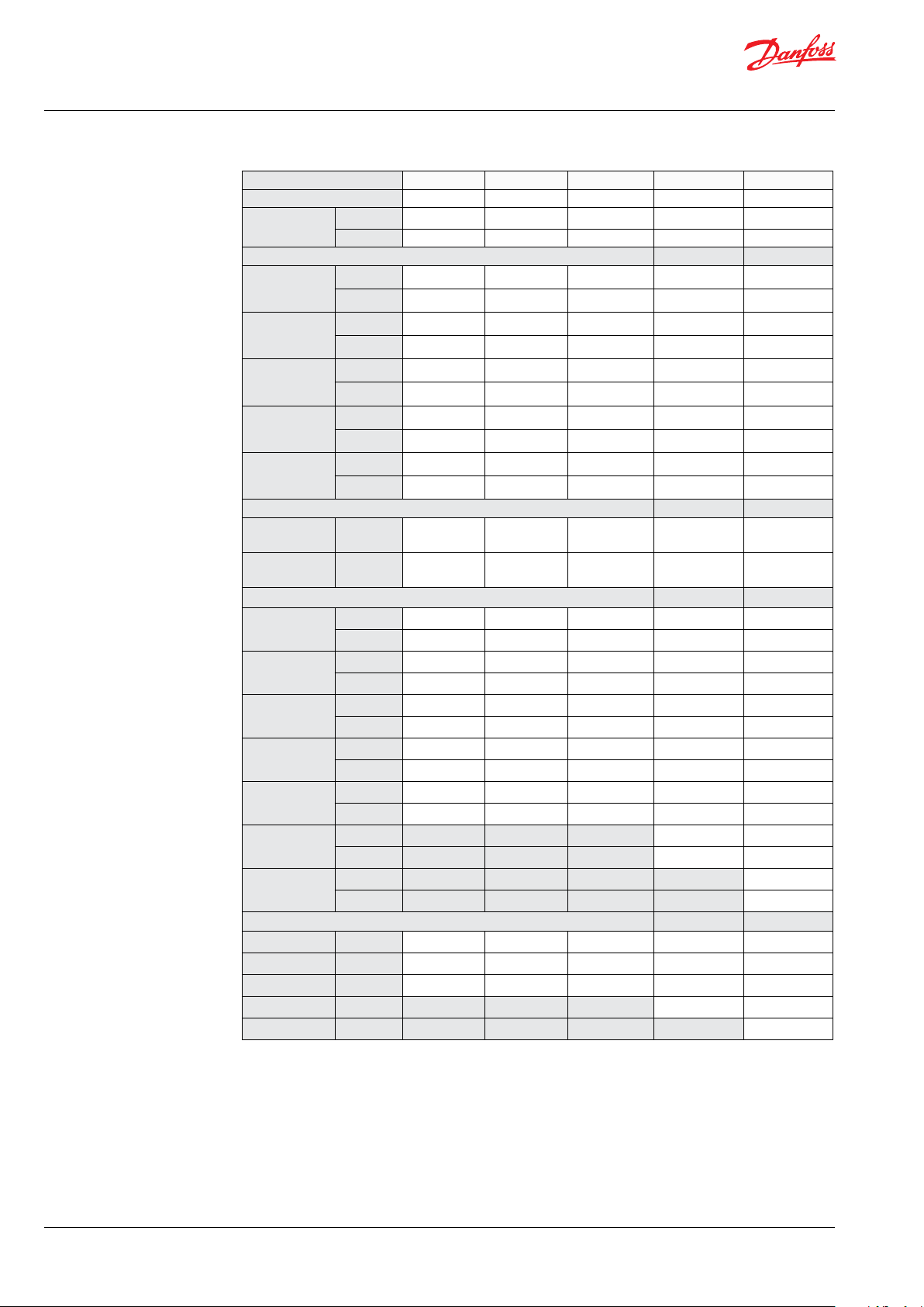
4.1 APP 53-924 Technical data
Pump size APP 53/1500 APP 65/1500 APP78 /1500 APP 86/1700 APP 92 /178 0
Code number 180B7806 180B7807 180B7808 180B7809 180B7810
Geometric
displacement
Pressure
Max. outlet
pressure
(MAWP)
Min. inlet
operating
pressure
Max. inlet
operating
pressure
Max. inlet
pressure peak
Min. outlet
pressure
Speed
Min. speed
continuous
Max. speed
continuous
Flow
Min. ow
700 rpm at
max. pressure
1000 rpm at
max. pressure
1200 rpm at
max. pressure
1500 rpm at
max. pressure
1700 rpm at
max. pressure
1780 rpm at
max. pressure
Eciency
1000 rpm
1200 rpm
1500 rpm
170 0 rp m
178 0 rp m
cm³/rev. 617 778 888 888 888
in³/re v. 37. 7 47. 3 54.2 54.2 54.2
1)
barg 83 83 83 70 70
psig 1,200 1,200 1,200 1,015 1,015
barg 2 2 2 2.5 3.5
psig 29 29 29 36 50
barg 5 5 5 5 5
psig 73 73 73 73 73
barg 10 10 10 10 10
psig 145 145 145 145 145
barg 30 30 30 30 30
psig 435 435 435 435 435
rpm 700 700 700 700 700
rpm 1,500 1,500 1,500 1,700 1,780
m³/ h 24 32 36 36 36
gpm 106 141 15 8 158 158
m³/ h 24 32 36 36 36
gpm 106 141 15 8 158 158
m³/ h 35 45 52 52 52
gpm 15 4 198 228 228 228
m³/ h 42 54 62 62 62
gpm 187 238 275 275 275
m³/ h 53 68 78 78 78
gpm 235 299 345 345 345
m³/ h 88 88
gpm 387 387
m³/ h 92
gpm 405
3)
% 88 88 89 89 89
3)
% 89 89 90 89 89
3)
% 88 89 89 88 88
3)
% 88 88
3)
% 87
4 | © Danfoss | DCS (im) | 2021.12
AI167386503010en-001301
Data sheet | APP 53-92 Pumps
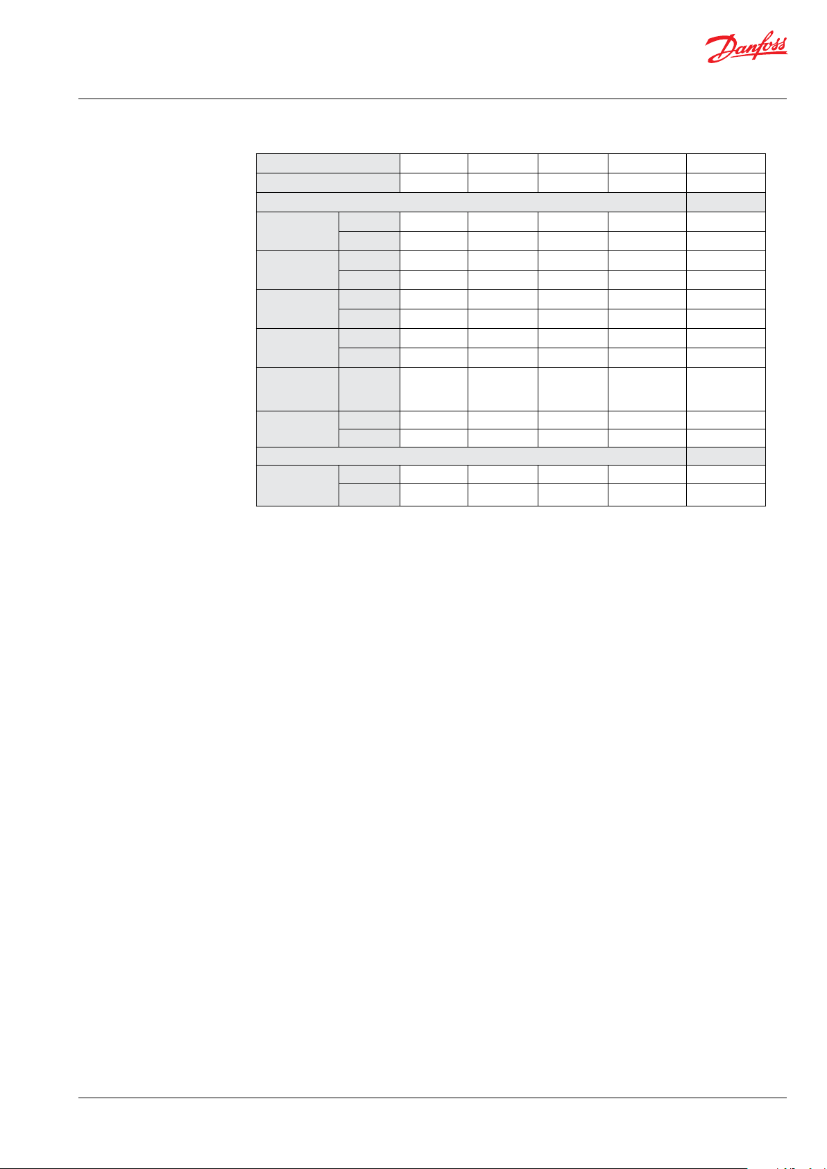
Pump size APP 53/1500 A PP 65/150 0 APP 78 /1500 APP 86/1700 APP 92/178 0
Code number 180B7806 180B7807 180B7808 180B7809 18 0B7810
Technical specications
2)
Media
temperature
Ambient
temperature
Weight (dry)
Weight
(operation)
°C 2–50 2-50 2–50 2-50 2-50
°F 36 –122 36-122 36 –122 36 -122 36-12 2
°C 0–50 0-50 0–50 0-50 0-50
°F 32–122 32-122 32–122 32-122 32-122
kg 196 196 196 196 196
lb 432 432 432 432 432
kg 204 204 204 204 204
6)
lb 450 450 450 450 450
Sound
pressure level
Footprint with
IE3 motor
db(A) 84-95 84-95 84-93 84-96 84-96
m² 1.49 1.49 1. 50 1.50 1.50
4)
Foot² 16.0 17. 0 16.1 16.1 16 .1
Typical motor size
Max.speed at
max. pres-
5)
sure
1)
Max. allowable working pressure at continuous operation. The pump is designed according to EN809, i.e. to
withstand hydrostatic test pressure (HTP) of 1.3 x MAWP. For lower and higher pressure, please contact Danfoss.
2)
Dependent on the NaCI concentration.
3)
Typical eciency at max. pressure after a system has been commissioned and run in.
4)
Maximum area covered with recommended IE3 motor congurations (excl. of space to service pump)
5)
IE3 and NEMA motors, 4-pole, current insulated ND non drive end bearing
6)
Operating with water
kW 132 160 160 200 200
HP 200 250 250 300 300
© Danfoss | DCS (im) | 2021.12
AI167386503010en-001301 | 5
Data sheet | APP 53-92 Pumps
100,00
120,00
140,00
160,00
180,00
200,00
220,00
240,00
260,00
280,00
300,00
320,00
340,00
360,00
380,00
400,00
Flow [gpm]
Speed [RPM]
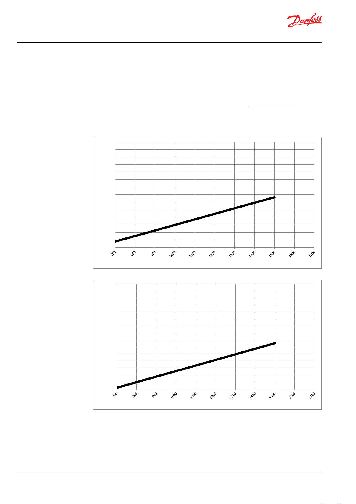
5. Performance curves
If the ow required and the rotation speed (rpm)
of the pump is known, it is easy to select the
pump, tting the application best, by using the
diagram below.
5.1 APP 53 ow at dierent rpm
90,00
85,00
80,00
75,00
70,00
65,00
60,00
55,00
50,00
Flow [m3/h]
45,00
40,00
35,00
30,00
25,00
20,00
Furthermore, this diagram shows that the
ow can be changed by changing the rotation
speed of the pump. The ow/rpm ratio is
constant, and the “required” ow can be
obtained by changing the rotation speed to a
corresponding value. Thus, the required rpm
can be determined as:
Required ow x Rated rpm
Required rpm =
Rated ow
6 | © Danfoss | DCS (im) | 2021.12
Speed [RPM]
AI167386503010en-001301
Data sheet | APP 53-92 Pumps
20,00
25,00
30,00
35,00
40,00
45,00
50,00
55,00
60,00
65,00
70,00
75,00
80,00
85,00
90,00
Flow [m3/h]
Speed [RPM]
100,00
120,00
140,00
160,00
180,00
200,00
220,00
240,00
260,00
280,00
300,00
320,00
340,00
360,00
380,00
400,00
Flow [gpm]
Speed [RPM]
5.2 APP 65 ow at dierent rpm
© Danfoss | DCS (im) | 2021.12
AI167386503010en-001301 | 7
Data sheet | APP 53-92 Pumps
20,00
25,00
30,00
35,00
40,00
45,00
50,00
55,00
60,00
65,00
70,00
75,00
80,00
85,00
90,00
Flow [m3/h]
Speed [RPM]
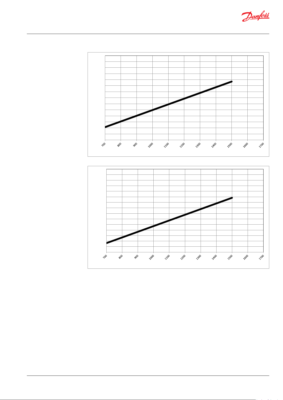
5.3 APP 78 ow at dierent rpm
8 | © Danfoss | DCS (im) | 2021.12
400,00
380,00
360,00
340,00
320,00
300,00
280,00
260,00
240,00
Flow [gpm]
220,00
200,00
180,00
160,00
140,00
120,00
100,00
Speed [RPM]
AI167386503010en-001301

Data sheet | APP 53-92 Pumps
100,00
120,00
140,00
160,00
180,00
200,00
220,00
240,00
260,00
280,00
300,00
320,00
340,00
360,00
380,00
400,00
Flow [gpm]
Speed [RPM]
5.3 APP 86 ow at dierent rpm
90,00
85,00
80,00
75,00
70,00
65,00
60,00
55,00
50,00
Flow [m3/h]
45,00
40,00
35,00
30,00
25,00
20,00
Speed [RPM]
© Danfoss | DCS (im) | 2021.12
AI167386503010en-001301 | 9

Data sheet | APP 53-92 Pumps
20,00
25,00
30,00
35,00
40,00
45,00
50,00
55,00
60,00
65,00
70,00
75,00
80,00
85,00
90,00
95,00
100,00
Fl ow [m3/h]
Speed [RP M]
100,00
120,00
140,00
160,00
180,00
200,00
220,00
240,00
260,00
280,00
300,00
320,00
340,00
360,00
380,00
400,00
420,00
Fl ow [gpm]
Speed [RP M]
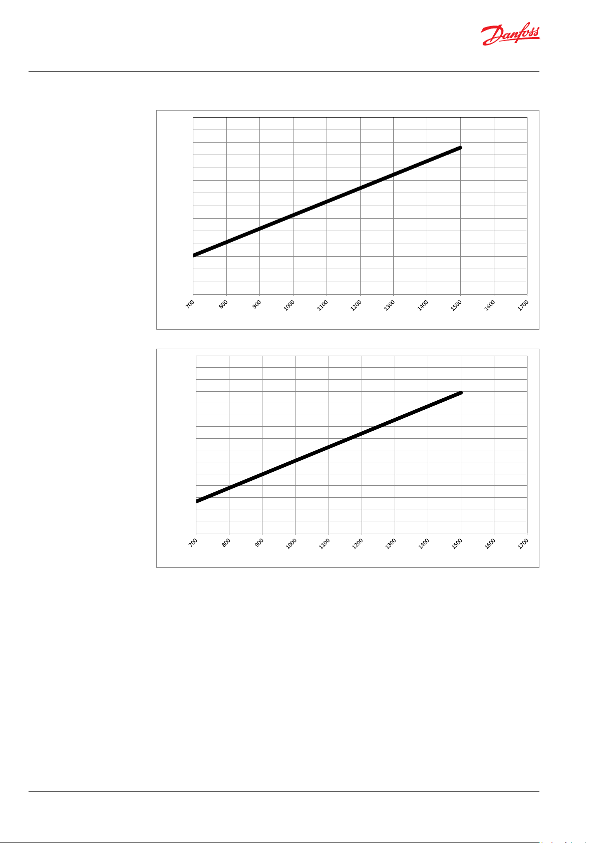
5.4 APP 92 ow at dierent rpm
10 | © Danfoss | DCS (im) | 2021.12
AI167386503010en-001301

Data sheet | APP 53-92 Pumps
6. Flushing valve curves
6.1 APP 53-92 integrated ushing valve
Pressure [barg]
3.5
3.0
2.5
2.0
1.5
1.0
0.5
0
0
100
200
300
400
500
Flow [l/min]
600
The power requirements can be determined using one of the following guiding equations:7. Motor requirements
3
l/min x barg 16.7 x m
/h x barg 0.35x gpm x psig
Required power = [kW] or [kW] or
Calc. factor Calc. factor Calc. factor
1 hp = 0.75 kW
1 gpm = 3.79 l/min
3
1 m
/h = 4.40 gpm
1 kW = 1.34 hp
1 l/min = 0.26 gpm
1 gpm = 0.23 m
3
/h
7.1 Calculation factor at 60 barg / 870 psig for APP 53-92
Name rpm
APP 53 150 0 528
APP 65 1500 534
APP 78 1500 534
APP 86 1700 528
APP 92 178 0 522
Calculation
factor
[Hp]
© Danfoss | DCS (im) | 2021.12
AI167386503010en-001301 | 11

Data sheet | APP 53-92 Pumps
8. Temperature and
corrosion
8.1 Operation
The chart below illustrates the corrosive
resistance of dierent types of stainless steel
related to NaCl concentration and temperature.
All wetted parts of the APP pump are made of
Duplex or Super Duplex.
º
80
C
Duplex
70
60
50
316L
40
30
20
100
160 1600
1000
10 000
16000
If the water pump is operated at high salinity
always ush the water pump with fresh water at
operation stop in order to minimize the risk of
crevice corrosion.
NaCI vs. temperature
Super Duplex
-
100 000
160000
CI
ppm
NaCI
ppm
9. Installation See example below on how to mount the pump
and connect it to an electric motor or combustion engine (special coupling).
For further instruction on installation of coupling
see APP Pump Instruction 180R9368.
If alternative mounting is required. please
contact your Danfoss sales representative for
further information.
Note: Do not add any axial or radial loads to the
pump shaft.
12 | © Danfoss | DCS (im) | 2021.12
AI167386503010en-001301

Data sheet | APP 53-92 Pumps
9.1 Filtration
Proper ltration is crucial for the performance,
maintenance and warranty of your pump.
Protect your pump, and the application in which
it is installed, by always ensuring that all ltration
specications are met, and by always changing
lter cartridges according to schedule.
Since water has very low vicosity, Danfoss APP
pumps have been designed with very narrow
clearances in order to control internal leakage
rates and improve component performance.
To minimize wear on the pump, it is therefore
essential to lter inlet water properly.
The main lter must have a ltration eciency of
99.98% at 10 m. We strongly recommend that
you always use precision depth lter cartridges
rated 10m abs. ß
≥5000.
10
Please note that we do not recommend bag
lters or string-wound lter cartridges, which
typically have only 50% ltration eciency. This
means that out of the 100,000 particles that
enter such lters, 50,000 particles pass right
through; compare this to precision depth lters
that are 99.98% ecient, and only allow 20 of the
same 100,000 particles to pass through.
For more information on the importance of
proper ltration, including explanation of
ltration principles, denitions and guidance on
how to select the right lter for your pump,
please consult our Filtration information and
specications (Danfoss document number
521B1009).
Noise
Since the pump unit is typical mounted on a
frame or bell housing the overall noise level can
only be determined for a complete system. To
minimize vibrations and noise throughout the
system, it is therefore very important to mount
the pump unit correctly on a frame with
anti-vibration-dampeners, and to use exible
hoses rather than metal pipes where possible.
The noise level is inuenced by:
• Pump speed:
High rpm generates more uid/structure
borne pulsations/vibrations than low rpm,
because of higher frequency.
• Discharge pressure:
High pressure generates more noise than
low pressure.
• Pump mounting:
Rigid mounting generates more noise than
exible mounting, because of structureborne vibrations. Be sure to use dampeners
when mounting.
• Connections to pump:
Pipes connected directly to the pump make
more noise than exible hoses, because of
structure-borne vibrations.
• Variable frequency drives (VFD):
Motors regulated by VFDs can produce
more noise if the VFD does not have the
right settings.
•
9.2 RO system with direct supply:
Inlet line:
a) Dimension the inlet line to obtain mini
mum pressure loss (large ow, minimum
pipe length, minimum number of bends/
connections, and ttings with low or no
pressure losses) .
Inlet lter:
b) Install an inlet lter (1) in front of the APP
pump (2). Please consult section 9.1,
“Filtration” for guidance on how to select
the right lter. Thoroughly clean pipes and
ush system prior to start-up.
Inlet pressure:
c In order to eliminate the risk of cavitation
and other pump damage, pump inlet
pressure must always be maintained
according to specications described in
item 4 about technical data.
Low pressure relief valve:
d) Install a low pressure relief valve (9) in order
to avoid system or pump damage in case
the pump stops momentarily or is spinning
backwards.
Monitoring pressure switch:
e Install a monitoring pressure switch (3)
between the lter (1) and the pump inlet.
Set the minimum inlet pressure according
to specications described in item 4 about
technical data. If the inlet pressure is lower
than the minimum pressure set, the
monitoring pressure switch must prevent
the pump from starting or from running.
Hoses:
f) Always use exible hoses (4) to minimize
vibrations and noise. Please consult the
Danfoss Hoses and hose ttings data
sheet (521B0909) for guidance.
Flushing valve:
g) For easy system lling and ushing, the
APP pump has an integrated valve (6).
Non-return valve:
h) A non-return valve (7) in outlet can be
installed in order to avoid backspin of the
pump. The volume of water in the
membrane vessel works as an accumulator
and will send ow backwards in case the
pump stops momentarily.
© Danfoss | DCS (im) | 2021.12
AI167386503010en-001301 | 13

Data sheet | APP 53-92 Pumps
High pressure safety or relief valve:
i) As the Danfoss APP pump begins to create
pressure and ow immediately after
start-up and regardless of any counter
pressure, a safety or pressure relief valve (8)
should be installed after the non-return
valve to prevent system damage and to
avoid high pressure peaks.
Note: If a non-return valve is mounted in the inlet
line, a low-pressure relief valve is also required
between the non-return valve and
pump as protection against high-pressure peaks.
Feed
Media filter
PI
PI
PI P I
Fresh water
permeat flush
M
PT
PI
Brine
Permeate
PI
14 | © Danfoss | DCS (im) | 2021.12
AI167386503010en-001301

Data sheet | APP 53-92 Pumps
connections
10.1 APP 5310. Dimensions and
© Danfoss | DCS (im) | 2021.12
AI167386503010en-001301 | 15

Data sheet | APP 53-92 Pumps
10.2 APP 65 - 92
16 | © Danfoss | DCS (im) | 2021.12
APP 65 - 92
AI167386503010en-001301

Data sheet | APP 53-92 Pumps
The APP 53-92 connections (inlet and outlet) can be adjusted in intervals of 45 degrees.
Please see typical installations with check valve VCM 92 mounted in the outlet port in the drawing
below. Non-standard congurations are available on request. For adjustment on site, please see
Installation, Operation and Maintenance Manual or contact Danfoss.
Non-standard conguration, turned 90 degrees left.
Non-standard conguration, turned 45 degrees left.Standard conguration
Non-standard conguration, turned 180 degrees .
© Danfoss | DCS (im) | 2021.12
AI167386503010en-001301 | 17

Data sheet | APP 53-92 Pumps
10.3 APP 53-92 with IE3 motor, IEC 315S - 4
10.4 APP 53-92 with IE3 motor, IEC 315M - 4
18 | © Danfoss | DCS (im) | 2021.12
AI167386503010en-001301

Data sheet | APP 53-92 Pumps
10.5 APP 53-92 with IE3 motor, IEC 315L 1-4
10.6 APP 53-92 with IE3 motor, IEC 315L 2 - 4
© Danfoss | DCS (im) | 2021.12
AI167386503010en-001301 | 19

Data sheet | APP 53-92 Pumps
11. Pump connections
11.1 APP 53 - 92
Use only Style 77DX coupling or equivalent.
3” Victaulic OSG LP Inlet
3” Victaulic OSG HP Outlet
20 | © Danfoss | DCS (im) | 2021.12
Connection
3” Inlet
connector
3” outlet
connector
1
) The installation instuction for Style 77DX is located in the Victaulic document I-100 Field Installation
Diameter
(A)
87. 8 m m
(3.46 inch)
87. 8 m m
(3.46 inch)
Victaulic
3” Vic. OSG
3” Vic. OSG
(B)
1)
Length
(C)
61.0 mm
(2.40”)
65.0 mm
(2.56”)
Material Max. Pressure Code number
Super
Duplex
Super
Duplex
10 barg
(145 psig)
80 barg
(1160 psig)
180Z1991
180Z1992
Handbook (htpp://static.victaulic.com)
AI167386503010en-001301

Data sheet | APP 53-92 Pumps
12. VCM 3” Victaulic
The non-return valve is designed for use in
Seawater Reverse Osmosis (SWRO) membrane
systems. In case the high-pressure pump stops
momentarily, the volume of water in the
membrane vessel may work as an accumulator
and will send ow backwards.
When using multiple pumps in parallel, the
non-return valve
12.1 Technical dat a
prevents the water from one pump to run into
the parallel-coupled pumps at start-up.
The VCM 92 is prepared for easy installation on
the high pressure outlet of APP 53-92, series 08
or higher..
Use only Style 77DX coupling or equivalent.
3” Vic. OSG
3)
Length
mm (inch)
180.5
(7.10)
Material2
Super
Duplex
Diameter
valve
)
1)
mm (inch)
87. 7
(3.45)
Typ e Connection
VCM 92
1)
The check valve is mounted directly in the outlet port with a ange with 8 screws M12 x 25.
2)
Wetted parts materials: Super Duplex, PEEK, PP, Hasteloy; FKM, NBR
3)
The installation instuction for Style 77DX is located in the Victaulic document I-100 Field Installation
3” outlet check
Victaulic
(outlet
connection)
Max.
2)
pressure
barg (psig)
83 (1.200) 180H0058
Code
number
Handbook (htpp://static.victaulic.com)
VCM VCM 92
Min. ow continously
Max. ow continously
Max pressure MAWP
Opening pressure barg 0.05- 0.08
Pressure loss at max. ow barg < 0.45
m/h 20
gpm 88
m/h 92
gpm 405
barg 83
psig 1200
psig 0.73 -1.16
psig < 6.5
© Danfoss | DCS (im) | 2021.12
AI167386503010en-001301 | 21

Data sheet | APP 53-92 Pumps
0
0,05
0,1
0,15
0,2
0,25
0,3
0,35
0,4
0,45
0,5
20 25 30 35 40 45 50 55 60 65 70 75 80 85 90 95 100
dP [ bar ]
Flow [ m3/h ]
Flow versus pre ssure for VCM 92
1
2
3
4
5
6
7
80 100 120 140 160 180 200 220 240 260 280 300 320 340 360 380 400 420 440
dP [ PSI ]
Flow [ GPM]
Flow versus pre ssure for VCM 92
1. Valve housing (Super Duplex)
2. Valve guide and valve stop (Super Duplex,
PEEK and PP)
3. Valve Cone (Super Duplex)
5. Spring (Hasteloy)
6. O-ring (NBR)
7. O-ring (FKM 75)
8. O-ring (NBR)
12.2 Flow versus pressure
Pressure drop curves for check valve VCM 92
22 | © Danfoss | DCS (im) | 2021.12
AI167386503010en-001301

Data sheet | APP 53-92 Pumps
13. Accessories
14. Service and warranty
Accessories Typ e Code num-
Coupling APP 53 - APP 92 IEC 315 Diameter: motor Ø80 mm, pump Ø50 180Z40 66
Coupling APP 53 - APP 92 IEC 280 Diameter: motor Ø75 mm, pump Ø50 180Z4081
Coupling kit APP 53 - APP 92 incl. bell housing IEC 315 Ø80/Ø50. IEC 315 Ø660/310 180Z4083
Coupling kit APP 53 - APP 92 incl. bell housing IEC 280 Ø75/Ø50. IEC280 Ø550/265 180Z4082
Base frame incl. vibration dampeners IEC 315 180Z06 61
Warranty
Danfoss APP pumps are designed for long
operation, low maintenance and reduced
lifecycle costs.
Pump shutdown:
The APP pumps are made of Duplex/Super
Duplex materials with excellent corrosion
properties. It is, however, always recommended
to ush the pump with freshwater when the
Provided that the pump has been running
according to the Danfoss specications, Danfoss
guarantees 8,000 hours service-free operation,
however, max. 18 months from date of
production.
system is shut down.
When stopping the pump for more than 1 day
ush the pump for 10 sec. Flushing through the
ushing valve of the pump without rotating the
pump is not enough for cleaning the inside of
the pump.
If Danfoss recommendations concerning
system-design are not followed, it will strongly
inuence the life of the APP pumps.
Other factors that aect pump performance and
lifetime include:
The pump can be ushed with biocide like the
membranes. The biocide must be compatible
with the materials used in our pump (materials
can be found in the parts list in the instruction
and operational manual).
- Insucient ltration
- Insucient bleeding and venting
- Running the pump at speed outside
specications.
Repair
In case of irregular function of the APP pump,
please contact Danfoss High Pressure Pumps.
- Supplying the pump with water at
temperature higher than recommended.
- Running the pump at inlet pressure outside
specications.
- Running the pump at outlet pressure
outside the specications.
- Wrong direction of rotation.
Maintenance
After 8,000 hours of operation it is strongly
recommended to inspect the pump and change
any worn parts, e.g. pistons and shaft
seal. This is done in order to prevent a potential
breakdown of the pump. If the parts are not
replaced, more frequent inspection is
recommended according to our guidelines.
ber
© Danfoss | DCS (im) | 2021.12
AI167386503010en-001301 | 23

© Danfoss | DCS (im) | 2021.12
AI167386503010en-001301 | 24
 Loading...